Instruction handbook Read the Instruction handbook before starting any work! Language English Translation Document No. 5.01032.05 Part No. 343509 Status 2013-03-13 Mono Power Unit / Power Module BUM 60 / BUS 60 E 5.01032.05
Transcript
Instruction handbook
Read the Instruction handbook before starting any work!
Copyright These Instruction handbook may be copied by the owner in any quantity, but only for internal use. This Instruction handbook may not be copied or reproduced, in whole or in part, for any other purposes. The use and disclosure of information contained in these Instruction handbook are not per-mitted. Designations and company marks contained in these Instruction handbook could be trade-marks, the use of which by third parties for their own purposes could violate the rights of the rights holder.
Preliminary information Warning: Insofar as this document is identified as being preliminary information, the follow-ing applies: this version is regarded as providing advance technical information to users of the described devices and their functions at an early enough time in order to adapt to any possible changes or expanded functionality. This information must be regarded as being preliminary, as it has not yet passed through Baumüller's internal review process. In particular, this information is still subject to changes, thus no legal liability can be derived from this preliminary information. Baumüller assumes no liability for damages that might arise from this possibly faulty or incomplete version. If you detect or suspect any content errors and/or major form errors in this preliminary infor-mation, we request that you notify the Baumüller support specialist responsible for you. Please provide us, via this employee, with your insights and comments so that we can take them into account and include them when transitioning from the preliminary information to the final information (as reviewed by Baumüller). The conditions stipulated in the following section under "Obligatory" are invalid in case of pre-liminary information.
Obligatory These Instruction handbook are a part of the equipment/machine. These Instruction hand-book must be available to the operator at all times and must be in legible condition. If the equipment/machine is sold or moved another location, these Instruction handbook must be passed on by the owner together with the equipment/machine. After any sale of the equipment/machine, this original and all copies must be handed over to the buyer. After disposal or any other end use, this original and all copies must be destroyed.
When the present Instruction handbook are handed over, corresponding sets of operating in-structions of a previous version are automatically invalidated. Please note that the specifications/data/information are current values according to the printing date. These statements are not legally binding with regard to measurements, computation or calculations. Baumüller Nürnberg GmbH reserves the right, in developing its products further, to change the technical specifications and handling of it products concerned without prior notice.
No liability can be accepted concerning the correctness of these Instruction handbook unless otherwise specified in the General Conditions of Sale and Delivery.
These instruction handbook provides important information on handling the device. A prerequi-site for safe work is compliance with all specified safety notes and procedural instructions.
Additionally, the valid accident prevention regulations and general safety regulations applicable to the scope of application the device must be complied with.
Read the instruction handbook, particularly the safety notes chapter, completely before begin-ning any work on the device. The instruction handbook is part of the product and must be kept accessible to personnel at all times in the immediate vicinity of the device.
7of 82
Instruction handbook BUM 60 / BUS 60Document No.: 5.01032.05
Key to symbols1.2
1.2 Key to symbols
Warning notes Warning notes are identified by symbols in these instruction handbook. The notes are intro-
duced by signal words that express the extent of the danger.
It is imperative that these notes be complied with and are conscientiously regarded in order to prevent accidents, personal injury and material damage.
DANGER!....points out an immediately dangerous situation that will lead to severe injuries or death if not avoided.
WARNING!....points out a potentially dangerous situation that could lead to severe injuries or death if not avoided.
CAUTION!....points out a potentially dangerous situation that could lead to minor or slight inju-ries if not avoided.
NOTICE!....points out a potentially dangerous situation that could lead to material damage if not avoided.
Recommen-dations
NOTE!....highlights useful tips and recommendations, as well as information for efficient and problem-free use.
All specifications and notes in these instruction handbook were compiled taking into account the applicable standards and regulations, the state of the art and our knowledge and experience of many years.
The manufacturer assumes no liability for damages due to:m noncompliance with the instruction handbookm usage for other than the intended purposem usage by untrained personnel
The actual scope of delivery can vary in case of optional equipment, laying claim to additional order options, or on account of the latest technical changes to the explanations and represen-tations described herein.
The user bears the responsibility for performing service and initial operation in accordance with the safety regulations of the applicable standards and all other relevant governmental or local regulations concerning the dimensioning and protection of conductors, grounding, disconnec-tors, overcurrent protection, etc.
The person who carried out the mounting or installation is liable for any damage incurred when assembling or connecting the device.
1.4 Copyright protection
The instruction handbook must be treated confidentially. It is to be used exclusively by person-nel who work with the device. The consignment of the instruction handbook to third persons without the written permission of the manufacturer is prohibited.
NOTE!The specific contents, text, drawings, images and other representations are copy-righted and subject to industrial property rights. Any prohibited usage is punishable by law.
1.5 Other applicable documents
Components of other manufacturers are integrated into the device. For these purchased parts, hazard assessments have been performed by the respective manufacturers. The compliance of the design construction with the applicable European and national regulations has been de-clared for the components by the respective manufacturers.
Instruction handbook BUM 60 / BUS 60Document No.: 5.01032.05
9of 82
Spare parts1.6
1.6 Spare parts
WARNING!False or flawed spare parts can lead to damage, malfunction or complete fail-ure, thus endangering safety.Therefore:m Only use original spare parts of the manufacturer.
Procure spare parts through an authorized dealer or directly from the manufacturer.
1.7 Disposal
Insofar as no take-back or disposal agreement has been made, please disassemble units cor-rectly and properly recycle the constituent parts.
See also ZDisposal– ab Seite 69.
1.8 Guarantee provisions
The guarantee provisions are stated in a separate document of the sales documents.
The devices described herein may only be operated in accordance with the stipulated methods, procedures and conditions. Anything else not presented here, including the operation of devices in mounted positions, is not permitted and must be cleared with the plant on a case-by-case ba-sis. If the devices are operated in any other manner than as described within these instruction handbook, then all guarantee and warranty rights are rendered null and void.
1.9 Customer service
Our customer service is available to provide you with technical information.
Info on the responsible contact persons is available at all times via telephone, fax, mail or the Internet.
1.10 Terms used
The term „device“ or the item designation BM5XXX are also used in this documentation for this Baumüller product. A list of the abbreviations used can be found in ZAppendix A - Abbrevia-tions– ab Seite 73.
This section provides an overview of all of the important safety aspects for optimum protection of personnel as well as for the safe and problem-free operation.
2.1 Contents of the instruction handbook
Each person who is tasked with performing work on or with the device must have read and un-derstood the instruction handbook before working with the device. This also applies if the person involved with this kind of device or a similar one, or has been trained by the manufacturer.
2.2 Changes and modifications to the device
In order to prevent hazards and to ensure optimum performance, no changes, additions or mod-ifications may be undertaken on the device that have not been explicitly approved by the man-ufacturer.
11of 82
Instruction handbook BUM 60 / BUS 60Document No.: 5.01032.05
Usage for the intended purpose2.3
2.3 Usage for the intended purpose
The device is conceived and constructed exclusively for usage compliant with its intended pur-pose described in these instruction handbook.
The devices of the model series Mono Power Unit / Power Module BUM 60 / BUS 60 are either mains rectifier or active mains rectifier in combination with axis units with servo controller. De-vices are also available in graduated design size and performance classes.
The device Mono Power Unit / Power Module BUM 60 / BUS 60 is used exclusively as a con-verter for controlling a motor.
A device is considered as being used compliant with its intended purpose if all notes and infor-mation of these instruction handbook are adhered to.
WARNING!Danger arising from usage for an unintended purpose!Any usage that goes beyond the intended purpose and/or any non-compliant use of the device can lead to dangerous situations.
Therefore:m Only use the device compliant with its intended purpose.m Observe all specifications of these instruction handbook.m Ensure that only qualified personnel work with/on this device.m When configuring, ensure that the device is always operated within its specifica-
tions.m Mount the device on a wall that can sufficiently bear the load.m The device must always be operated within a control cabinet.m Ensure that the power supply complies with the stipulated specifications.m The device may only be operated in a technically flawless condition.m Only operate the device in combination with components approved by Baumüller
Nürnberg GmbH.m The device has been developed in such a manner that it fulfills the requirements
of the category C3 according to IEC 61800-3:2005. m The device is not intended to be connected to the public power supply system. To
operate the device in primary surroundings of the category C2/C1 (residential, business and commercial areas, directly on a public low-voltage power supply without an intermediate transformer), special measures to reduce the transient emissions (line-internal and radiated) must be provided for and certifiable by the system builder. Otherwise, EMC interference could occur without such additional measures.
The device will be used in commercial areas. Thus, the proprietor of the device is subject to the legal work safety regulations.
Along with the notes on work safety in these instruction handbook, the safety, accident preven-tion and environmental protection regulations valid for the area of application of this device must be complied with. Whereby:m The operating company must inform himself about the applicable work health and safety reg-
ulations and ascertain, in a hazard assessment, any additional hazards that could arise from the special working conditions in the use area of the device. These must then be implemented in the form of instruction handbook for operation of the device.
m These instruction handbook must be kept accessible to personnel working with the device at all times in the immediate vicinity of the device.
m The specifications of the instruction handbook must be adhered to completely and without ex-ception.
m The device may only be operated in a technically faultless and operationally safe condition.
2.5 Protective devices
The devices BUM 60 / BUS 60 comply with the protection class IP 20. All devices BUM 60 / BUS 60 must be installed in an appropriate control cabinet to meet the protection classification required in EN 61800-5-1, chapter 4.2.3.3.
DANGER!Risk of fatal injury from electrical current!There is an immediate risk of fatal injury if live electrical parts are contacted.
Therefore:m The device must be in operated inside of a control cabinet that provides protection
against direct contact of the devices and at least meets the requirements of EN 61800-5-1, Chapter 4.2.3.3.
Instruction handbook BUM 60 / BUS 60Document No.: 5.01032.05
13of 82
Training of the personnel2.6
2.6 Training of the personnel
WARNING!Risk of injury due to insufficient qualifications!Improper handling can lead to significant personal injury and material damage.
Therefore:m Certain activities can only be performed by the persons stated in the respective
chapters of these instruction handbook.
In these instruction handbook, the following qualifications are stipulated for various areas of ac-tivity:
m Operating personneln The drive system may only be operated by persons who have been specially trained, fa-
miliarized and authorized.n Troubleshooting, maintenance, cleaning, maintenance and replacement may only be per-
formed by trained or familiarized personnel. These persons must be familiar with the in-struction handbook and act accordingly.
n Initial operation and familiarization may only be performed by qualified personnel.
m Qualified personneln Electrical engineers authorized by Baumüller Nürnberg GmbH, and qualified electricians
of the customer or a third party who have learned to install and maintain Baumüller drive systems and are authorized to ground and identify electrical power circuits and devices in accordance with the safety engineering standards of the company.
n Qualified personnel have had occupational training or instruction in accordance with the respective locally applicable safety engineering standards for the upkeep and use of ap-propriate safety equipment.
The wearing of personal protective equipment is required when working in order to minimize health and safety risks.m The protective equipment necessary for each respective type of work shall always be worn
during work.m The personal safety signs present in each working area must be observed.
Protective work clothingshould be snug-fitting work clothes, with low tearing resistance, narrow sleeves and with no extending parts. It serves to primarily protect against...
No rings or chains should be worn.
Hard hatto protect against falling down and flying around objects.
Safety shoesto protect against heavy objects falling down.
Protective glovesto protect hands against friction, abrasion, puncturing or more severe injuries, as well as contact with hot objects.
Wear for special work.
Protective eye wearto protect the eyes against flying around objects and sprayed liquids.
Instruction handbook BUM 60 / BUS 60Document No.: 5.01032.05
15of 82
Special hazards2.8
2.8 Special hazards
In the following section, the remaining marginal risks will be stated that have been identified as a result of the hazard analysis.
Observe the safety notes listed here and the warning notes in the further chapters of this Instruc-tion handbook to reduce health risks and dangerous situations.
Electrical current
DANGER!Risk of fatal injury from electrical current!There is an immediate risk of fatal injury if live electrical parts are contacted. Damage to the insulation or individual components can be life-threatening.
Therefore:m Switch off the electrical power immediately in case of damage to the power supply
insulation.m Only allow work on the electrical system to be performed by qualified personnel.m Switch off the current when any kind of work is being performed on the electrical
system and ensure safety before switching on again.
Danger from residual en-ergy
DANGER!Risk of fatal injury from electrical current!Stored electric charge.
Discharge time of the system = discharge time of the device with the longest DC link discharge time.
Therefore:m Do not touch electrically live parts before taking into account the discharge time of
the capacitors.m Pay attention to the corresponding notes on the device.m If additional capacitors are connected to the DC link, the DC link discharge can
take a much longer time. In this case, the necessary waiting period must itself be determined or a measurement made as to whether the equipment is de-energized. This discharge time must be posted, together with an IEC 60417-5036 (2002-10) warning symbol, on a clearly visible location of the control cabinet.
WARNING!Risk of injury from moving components!Rotating components and/or components moving linearly can result in severe injury.
Therefore:m Do not touch moving components during operation.m Do not open any covering during operation.m The amount of residual mechanical energy depends on the application. Powered
components still turn/move for a certain length of time even after the power supply has been switched off. Ensure that adequate safety measures are taken.
2.9 Fire fighting
DANGER!Risk of fatal injury from electrical current!There is a risk of electric shock if an electrically-conductive, fire-extinguishing agent is used.
Therefore:m Use the following fire-extinguishing agent:
ABC powder / CO2
Instruction handbook BUM 60 / BUS 60Document No.: 5.01032.05
17of 82
Safety equipment2.10
2.10 Safety equipment
WARNING!Risk of fatal injury due to non-functional safety equipment!Safety equipment provides for the highest level of safety in a facility. Even if safety equipment makes work processes more awkward, under no circumstances may they be circumvented. Safety can only be ensured by intact safety equipment.
Therefore:m Before starting to work, check whether the safety equipment in good working order
and properly installed.
2.11 Conduct in case of danger or accidents
Preventive measures
m Always be prepared for accidents or fire!m Keep first-aid equipment (e.g. first-aid kits, blankets, etc.) and fire extinguishers readily ac-
cessible.m Familiarize personnel with accident alarm, first aid and rescue equipment.
And if some-thing does happen: re-spond prop-erly.
m Stop operation of the device immediately with an EMERGENCY Stop.m Initiate first aid measures.m Evacuate persons from the danger zone.m Notify the responsible persons at the scene of operations.m Alarm medical personnel and/or the fire department.m Keep access routes clear for rescue vehicles.
The following symbols and information signs are located in the working area. They refer to the immediate vicinity in which they are affixed.
WARNING!Risk of injury due to illegible symbols!Over the course of time, stickers and symbols on the device can become dirty or oth-erwise unrecognizable.
Therefore:m Maintain all safety, warning and operating labels on the device in easily readable
condition.
Electrical voltageOnly qualified personnel may work in work areas that identified with this.
Unauthorized persons may not touch working materials marked correspondingly.
DANGER!Risk of fatal injury from electrical current!Stored electric charge.
Discharge time of the system = discharge time of the device with the longest DC link discharge time.
Therefore:m Do not touch electrically live parts before taking into account the discharge time of
the capacitors.m Pay attention to the corresponding notes on the device.m If additional capacitors are connected to the DC link, the DC link discharge can
take a much longer time. In this case, the necessary waiting period must itself be determined or a measurement made as to whether the equipment is de-energized. This discharge time must be posted, together with an IEC 60417-5036 (2002-10) warning symbol, on a clearly visible location of the control cabinet.
Instruction handbook BUM 60 / BUS 60Document No.: 5.01032.05
The following dimension drawings show the main dimensions of the devices. By means of the dimension drawings the space requirements within the control cabinet are determined. The di-mension drawings in ZDrilling patterns– from page 40 must be used in order to do the required drillings / segments.
NOTE!All dimensions in mm.
Figure 3: Dimensions
23of 82
Instruction handbook BUM 60 / BUS 60Document No.: 5.01032.05
Weight3.2
3.2 Weight
Weight without controller cassette ca. 7 kg
3.3 Operating requirements
3.3.1 System types
There are three basic types of the current supply systems regarding the grounding, which con-form with DIN VDE0100 part 300 and IEC 60364:m The TN system has a directly grounded point (system grounding). The cabinet of the electrical
installation is connected via the protective conductors and PE conductors with this point.m The TT system has a directly grounded point (system grounding). The cabinet of the electrical
installation is connected with grounding electrodes. The grounding electrodes are separated from system grounding.
m The IT system has no direct connection between the active conductors (L1, L2, L3, N) and grounded parts (PE). The cabinet of the electrical installation is grounded. The separation is reached by using an isolating transformer or an independent current source (generator, bat-tery).
Supported system types
NOTICE!The operation of the BUM 60 / BUS 60 is possible at TN / TT systems, only.
Industrienetz mit hart- oder niederimpedant geerdetem Sternpunkt (TN-Netz oder TT-Netz)
Inductance (sum of power supply inductance and choke inductance)
min. uk = 0,4 % max. uk = 4 %
Rated power supply voltage/frequency device 1) (UAC) 3 x 400 V 50/60 Hz
Absolute minimum supply voltage device1) (UAC)Absolute maximum supply voltage device1) (UAC)
3 x 207 V / 50/60 Hz3 x 528 V / 50/60 Hz
Absolute minimum frequency 3)
Absolute maximum frequency 3)47 Hz63 Hz
Harmonics (power supply voltage)EN 61800-3, chap. 5.2.1, class 3
THDU b 10 %
Unbalanced power supply voltage EN 61000-2-4, tab. 1, class 3
max. 3 %
Voltage variations/-fluctuationsEN 61200-2-4, class 3
+/-10 %+10 % to -15 % at a period of b 1 min
Control voltage 2) (UDC)EN 61131-2:1994, table 7
+ 24 V +/-10 %
/ supply system
1) Rated voltage is 400 V. With lower supply voltages the output power of the device is reduced.
2) The control voltage must accord to PELV (EN 61800-5-1, chapter 3.21) or SELV (EN 61800-5-1, chap. 3.35). At control voltage of < 24 V the ventilation power output is reduced. Therefore, it may be necessary, to reduce the output currents as well. If you comply with UL 508C the current is limited to 4 A with fuses according UL 248 and the voltage is limited to max. 30 VDC.
3) Rate of change of the power supply frequency 1 Hz/s at a maximum (EN 61000-2-4, class 3).
Instruction handbook BUM 60 / BUS 60Document No.: 5.01032.05
25of 82
Operating requirements3.3
3.3.3 Environmental requirements
Transport temperature range - 25 °C bis + 70 °C
Transport climatic categoryEN 60721-3-2
2 K 3
Storage temperature range - 25 °C bis + 55 °C
Storage climatic classEN 60721-3-1
1 K 4
Operation environment Industrial system 3)
Operation temperature range 1) min. 5 °C to max. 45 °C (with power derating 3 %/ °C) up to 55 °C))
Operation climatic classEN 60721-3-3
3 K 3
Mounting height 2) absolute altitude up to 1000 m
Humidity (operation)EN 60721-3-3
relative humidity: 5 % to 85 % no condensationand
absolute humidity: 1 g/m3 to 25 g/m3
Ionizing and non-ionizing radiation < measurable range
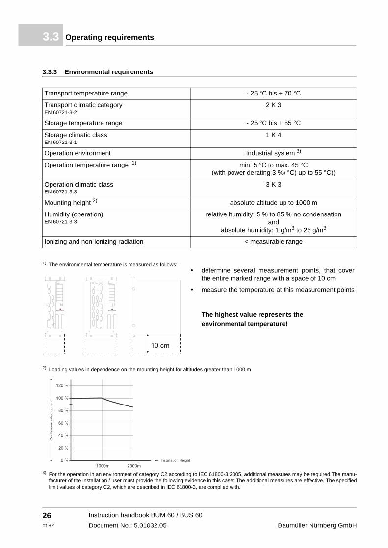
1) The environmental temperature is measured as follows:determine several measurement points, that cover the entire marked range with a space of 10 cm
measure the temperature at this measurement points
The highest value represents the environmental temperature!
2) Loading values in dependence on the mounting height for altitudes greater than 1000 m
3) For the operation in an environment of category C2 according to IEC 61800-3:2005, additional measures may be required.The manu-facturer of the installation / user must provide the following evidence in this case: The additional measures are effective. The specified limit values of category C2, which are described in IEC 61800-3, are complied with.
NOTICE!Normally, non-conductive pollution occurs. Conductive pollution is unacceptable. Conductive pollution can lead to the destruction of the device. The customer is re-sponsible for destructions, which were caused by pollution due to conductive materi-als or components.
Ballast resistor RB (only BUM 60) Peak power of ballast resistor Continuos outputExternal ballast resistor 7)
10 kW / 1 s250 W
min. 60 Ω
Max. switch-on time / ratio 1,5 s / 1 : 33
Power loss in rated operation, without low-voltage supply, without ballast
60 W 60 W 110 W 110 W 130 W 170 W
*
WARNUNG!With a single-phase connection, neither of the two lines must have ground potential!
Instruction handbook BUM 60 / BUS 60Document No.: 5.01032.05
27of 82
Electrical data3.4
1) Single-phase connection possible. Voltage difference between phases must not exceed +/- 3,0 %2) All nominal values refer to a connection voltage of 400 V
With a single-phase connection, the rated DC link voltage is reduced by 35 %3) With a single-phase connection, the value is reduced by 66%4) With a single-phase connection, the value is reduced by 50%5) The current information depends on the controller type
Digital controller: effective value for sinus commutation6) For a maximum of 200 ms without preloading using E/V-controller
For a maximum of 1 s without preloading using V-controller The load cycle must be dimensioned, that the effective value of the output current does not exceed the rated current.
7) If UL508C has to be observed: the external ballast resistor must protect itself from overheating.8) Do use fuses, which have a I2t-value at the working point of max. 510 A2s .
If UL508C has to be observed: do use fuses 32A/1000V: 3NE4 101 manufactured by Siemens (Item-No. 101 940 Baumüller). The cor-responding fuse-carrier is available from Baumüller (Item-No. 101 960). You may even use UL-approved fuses listed in the table below. In the table below we have listed UL-approved fuses and fuses that are not UL-approved. Please observe, that the listed fuses are of different design and that you have to use corresponding fuse-carriers. Not all fuses listed below can be inserted into the above listed fuse-carrier from Baumüller!
Full range fuses (semiconductor and line protection)
9) The output voltage is a pulse-commutated DC. The setting range refers to the r.m.s. value of the fundamental wave.10) R.m.s. value at an ambient temperature of 45 °C.11) The rated output current must be reduced between 45 °C and 55 °C. The rated output current is calculated according the following
NOTEThe use of the commutating choke BK3-0025/0030, Inom = 25 A, L = 1,18 mH with copper busbar part no. 368377 or with terminals part no. 399136 is recommended, if the device BUM60-12/24 operates at full capacity.
Reason:
The ripple current through the DC link capacitor is high, if the device operates at full capacity. The current can be reduced by connecting ahead a commutating induc-tance accordingly the DC link capacitor load is reduced and therefore is heated up to a lesser extent and a longer live cycle of the DC link capacitors can be expected than by operating the device on the power limit without using a commutating choke.
Instruction handbook BUM 60 / BUS 60Document No.: 5.01032.05
The single power unit BUM 60 and the power module BUS 60 complement the Baumüller Mod-ular System in the medium performance range.
Plug-in V-controller cards are supposed to be used for closed-loop control. All V-controller com-binations up to three printed circuit levels can be used.
HINWEIS!The controller is fitted as plug-in card and the description, which is available sepa-rately, contains the respective properties and technical data.
The single power unit BUM 60 consists of the feed current converter on the power supply side and the motor-end inverter.The power module BUS 60 consists only of the motor-end inverter. The power supply is con-nected via the DC link.
31of 82
Instruction handbook BUM 60 / BUS 60Document No.: 5.01032.05
General4.1
4.1.1 Description of function
The whole unit BUM 60 consists of the three parts feed current converter on the power supply side, motor-end inverter and controller plug-in card. This documentation does not refer to the available controllers. Each controller comes with its own documentation.f Feed current converter on the power supply side
The feed current converter is an non-controllable B6 rectifier with starting current load relief and ballast circuit.
f Starting current load relief A direct switch-on of the unit would lead to an inadmissibly high level of impulse current, be-cause of the DC link capacity without starting current load relief. To avoid this impulse current, the starting current is limited by a resistor.
f Ballast circuit In certain operation modes feeds the motor energy to the unit. This energy is stored and leads to a higher DC link voltage. To avoid reaching the over voltage switch-off threshold, the feed-back energy is transformed to heat in an internal or external ballast resistor.
f Motor-end inverter The motor-end inverter comprises the IGBT power unit and the accompanying detectors. The detectors supply on the one hand measurement signals and on the other hand the self-pro-tection facilities of the power electronic. The control of the inverter is run by the controller.
The power module BUS 60 does not include the parts feed current converter with starting load relief and ballast circuit. The unit consists only of the motor-end inverter and the controller plug-in. With this power module - in connection with units, containing feed current converters - multi axle systems can be built, that enable a power transfer via the DC link.
NOTICE!Damage due to unauthorized transport!Transport handled by untrained personnel can lead to a substantial amount of mate-rial damage.
Therefore:m The unloading of the packages upon delivery as well as the in-house transport
should only be done by trained personnel.m Contact Baumüller Nürnberg GmbH sales office if necessary.
WARNING!Danger of mechanical hazard!Secure devices against falling down.
Therefore:m Use appropriate handling material.
5.2 What to observe when transporting
For initial transport of the device, it is packed at the manufacturer. If the device is to be further transported, ensure that the following conditions are met throughout the entire transport:m Climate class 2 K 3 as per EN 60721-3-2m Temperature range - 30 °C up to + 70 °Cm Vibration, shock, continuous shock class 2 M 1 as in EN 60721-3-2
35of 82
Instruction handbook BUM 60 / BUS 60Document No.: 5.01032.05
Transport inspection5.3
5.3 Transport inspection
Upon receiving the delivered goods, immediately examine them for completeness and transport damage.
If there is outwardly visible transport damage, proceed as follows:m Do not accept the delivery or conditionally accept it with reservations.m Note the extent of the damage on the transport documents or on the delivery note of the trans-
port agent.m Immediately file a complaint with the freight carrier. Have the complaint confirmed in writing
and immediately contact the responsible representative of Baumüller Nürnberg GmbH.
NOTE!The device may not be operated if there is visible transport damage!
5.4 Unpacking
After having received the still packaged device:
h Avoid transport shocks and hard jolts, e.g. when putting an item down.
If no transport damage is visible:
h Open the packaging of the device.
h Verify the delivery scope based on the delivery note.
File a claim with the responsible Baumüller representative if the delivery is incomplete.
NOTE!Claim each individual deficiency as soon as it has been detected. Damage claims can only be validly asserted within the claim registration period.
5.5 Disposal of the packaging
The packaging consists of cardboard, plastic, metal parts, corrugated cardboard and/or wood.
h When disposing of the packaging, comply with the national regulations.
In this chapter we describe the mechanical mounting of the device into a control cabinet.
Mounting consists of the following steps:1 Prepare mounting (drill holes/cut-out segments)2 Install device
6.1 Safety notes
NOTE!Mounting shall only be performed by employees of the manufacturer or by other qual-ified personnel.
Qualified personnel are persons who – on account of their occupational training, ex-perience, instruction and knowledge of relevant standards and stipulations, accident prevention regulations and operating conditions – are authorized by the persons re-sponsible for the safety of the facilities to perform the respective activities that are necessary, while at the same time recognizing and preventing any potential risks. The qualifications necessary for working with the device are, for example:m Occupational training or instruction in accordance with the standards of safety en-
gineering for the care and use of appropriate safety equipment.
37of 82
Instruction handbook BUM 60 / BUS 60Document No.: 5.01032.05
Safety notes6.1
WARNING!Danger as a result of faulty mounting!The mounting requires qualified personnel with adequate experience. Faulty mount-ing can lead to life-threatening situations or substantial material damage.
Therefore:m Only allow mounting to be performed by employees of the manufacturer or by oth-
er qualified personnel.
WARNING!Danger of mechanical impact!Secure devices against falling down.
Therefore:m Use appropriate means of transport.
NOTICE!Danger due to electrostatic discharge.The connecting terminals of the device are partially at risk due from ESD.
Therefore:
Please heed the respective notes.
CAUTION!Danger due to sharp edges.If the device is lifted with unprotected hands during mounting, palms or fingers can be cut. If the device falls, feet could be injured.
Therefore:m Ensure that only qualified personnel, who are familiar with the safety notes and as-
Based on the planning documents and the drilling pattern, the cutout sections and the positions of the attachment drill holes can be determined.
NOTICE!Property damage due to conductive contamination.Therefore:m When performing installation work of any kind, it must be ensured that no foreign
material (e.g. drill shavings, copper strands, etc.) gets into the device as a result. m If possible, the drilling of the holes should be done before mounting the device and
the configuring of the cables should take place outside of the control cabinet. If this is not possible, the device must be appropriately covered. Remove this covering again prior to start!
CAUTION!Eye injury due to flung particles.Metal particles are flung when making the drill holes and the cutout sections.
Therefore:
Wear protective eye wear!
h Preparing drill holes and cutout sections.
Instruction handbook BUM 60 / BUS 60Document No.: 5.01032.05
39of 82
Preparing for mounting6.2
6.2.1 Drilling patterns
Use the drilling pattern to make the necessary drill holes/cutout sections.
NOTE!Consider the minimum clearances for cooling when making the drill holes.
All dimensions in millimeters [mm].
page 26Further notes see ZDimensions– on page 23 and ZEnvironmental requirements– on
.
How to determine the required space in the control cabinet, see ZDimensions– on page 23.
Tolerance specifica-tions Drill hole dimensioning ±0.2 mm
Relative tolerance of discretionary divisions ±0.1 mm
h Install the units vertically in a switching cabinet. If there are several units, mount them next to one another.
NOTICE!It is crucial to comply with the ventilation measures listed below. Ignoring these measures can lead to the unit overheating.
h Die Belüftung muss von unten nach oben erfolgen.
h Für ungehinderte Luftzufuhr ist zu sorgen.
h Ensure that there is a minimum clearance of at least 100 mm above and below the unit and ensure that there is enough cooling air that can circulate freely!
h The temperature of the coolant 100 mm below the devices may be up to 45° C. At higher tem-peratures (up to a maximum of 55° C), reduce the power of the devices by 3 % per degree Celsius.
h Do not locate any additional sources of heat above or below the devices.
h Avoid degrees of contamination 3 and 4 according to standard DIN EN 61800-5-1, chapter 4.3.6.1.2, (table 6). The devices are suitable for use in enclosed workshop (VDE0558 Part 1a, Sections 5.4.3.2.1 and 5.4.3.2.2).
DANGER!Risk of fatal injury from electrical current!Stored electric charge.
The discharge time of the device is > 1 min.
Instruction handbook BUM 60 / BUS 60Document No.: 5.01032.05
In this chapter we describe the electric installation of the device. The mechanical installation is described in ZMounting– on page 37.
Before installing assure, that the technical preconditions are fulfilled:1 Check the requirements to the electrical power supply and check if the existing power supply
is suitable.2 Check the requirements to the electrical cables and provide the according cables.3 Check the characteristics of the connections and configure the connections accordingly.
7.1 Safety instructions
NOTE!Installation shall only be performed by employees of the manufacturer or by other qualified personnel.
Qualified personnel are persons who – on account of their occupational training, ex-perience, instruction and knowledge of relevant standards and stipulations, accident prevention regulations and operating conditions – are authorized by the persons re-sponsible for the safety of the facilities to perform the respective activities that are necessary, while at the same time recognizing and preventing any potential risks. The qualifications necessary for working with the device are, for example:m Occupational training or instruction, and the authorization to commission, ground
and mark electrical power circuits and devices in accordance with the standards of the safety engineering.
m Occupational training or instruction, in accordance with the standards of work safe-ty, for the care and use of appropriate safety equipment.
43of 82
Instruction handbook BUM 60 / BUS 60Document No.: 5.01032.05
Safety instructions7.1
WARNING!Danger because of faulty installation and initial commissioning!Installation and commissioning require qualified personnel with adequate experi-ence. A installation fault can cause danger situations or large damage of property.
Therefore:m Only personnel from manufacturer or qualified personnel operate while installation
and initial commissioning
DANGER!Risk of fatal injury from electrical current!Inevitably, when operating this electrical device, certain parts of it are energized with hazardous voltage.
Therefore:m Pay heed to areas on the device that could be dangerous during the electrical in-
stallation.m Pay heed to areas on the device that could still be electrically energized after op-
eration.
Danger from residual en-ergy
DANGER!Risk of fatal injury from electrical current!Stored electric charge.
Discharge time of the system = discharge time of the device with the longest DC link discharge time.
Therefore:m Do not touch electrically live parts before taking into account the discharge time of
the capacitors.m Pay attention to the corresponding notes on the device.m If additional capacitors are connected to the DC link, the DC link discharge can
take a much longer time. In this case, the necessary waiting period must itself be determined or a measurement made as to whether the equipment is de-energized. This discharge time must be posted, together with an IEC 60417-5036 (2002-10) warning symbol, on a clearly visible location of the control cabinet.
DANGER!Risk of fatal injury from electrical current!During the routine test of these devices, a voltage test is performed by Baumüller Nürnberg GmbH in accordance with EN 61800-5-1, Section 5.2.3.2. It is thus unnec-essary for the customer to do this.
Therefore:m Subsequent tests of the devices using high voltages may only be performed by
Baumüller Nürnberg GmbH.m Disconnect the converter from the system during high-voltage testing!
7.3 Requirements to the supply system
For all important data, see ZRequirements to the energy supply / supply system– from page 25.
Minor deviations from requirements in the power supply can lead to malfunctioning of the de-vice. If the power supply deviates too much from the requirements, the device can be destroyed.
The devices may only be operated in industrial networks.
The destruction of the device can cause personal injury.
DANGER!Risk of fatal injury from electrical current!If the requirements for the power supply are not complied, the device can be dam-aged or destroyed, thereby greatly endangering individuals.
Therefore:m Prior to installation, ensure that the demands for power supply have been fulfilled.
7.4 Requirements to the connecting cables
h Take into account IEC/EN 60204-1, Chapter 13 when selecting the cable.
h The protective ground cross-section of the cable must be compliant with IEC/EN 60204-1, Section 5.2, Tab. 1.
h A fixed connection for the protective ground conductor is mandatorily specified for operation of the device.
h Use copper cable approved for a minimum of 60 °C (drives < 3 x 100 A) or 75 °C (drives ≥ 3 x 100 A), if comply with UL 508C.
Instruction handbook BUM 60 / BUS 60Document No.: 5.01032.05
45of 82
Protection of the device and the cable7.5
7.5 Protection of the device and the cable
Fuses must be installed to protect this device and the cables against overload and possible damage/destruction through the electrical power supply. For data on the required fuses, see ZFull range fuses (semiconductor and line protection)– on page 28.
7.6 PE connection and RCD compatibility
Depending on the functional principle, leakage current >3.5 mAAC or >10 mADC can flow through the protective ground conductor. Consequently, a stationary ground conductor connec-tion in accordance with EN 61800-5-1 is required.
DANGER!Risk of fatal injury from electrical current!This product can cause direct and/or alternating current in the protective ground con-ductor.
The leakage current, due to the functional principle of the device, can lead to prema-ture triggering of the fault current protective device or generally prevent triggering of it.
Therefore:m Wherever a differential current device (RCD) is used for protection in case of direct
or indirect contact, only an RCD of the type B is permitted on the power supply side of the device.
m Otherwise a different protective measure must be utilized, such as separation from the surroundings by means of double or enhanced isolation, or separation from the power supply system by means of an isolating transformer, for example.
7.7 Installation requirements with regard to EMC
NOTE!The emission of radio frequency interference (RFI) is to a great extent dependent on the wiring, spatial expansiveness and the arrangement of the components in the sys-tem. Ensuring electromagnetic compatibility compliance in accordance with legal re-quirements is therefore only possible on the completely assembled system and is thus the responsibility of the system manufacturer or proprietor (re Art. 6, Par. 9 of the EMVG; European EMC law).
HINWEIS!The important information on EMC-compliant installation can be found in these in-struction handbook. Additional notes on building a CE-compliant system, that are im-perative to take heed of, can be found in the Baumüller manual „Mains filter BFN“. This manual can be obtained from Baumüller Nürnberg GmbH.
m Use Baumüller motor cables and Baumüller components.m Use a suitable mains filter of Baumüller Nürnberg GmbHm Mount all components to one single mounting board with well electroconductive surface (e.
g. galvanized steel plate).m Establish the ground connection converter/ground plane as short as possible (< 30 cm) with
fine-wired cables and a great cross section (> 10 mm2).m Assure, that the motor cables always consist of one piece.
Do not interrupt the motor cables e. g. by terminals, conductors, fuses a.s.o.m Run the cables directly on the surface of the grounded mounting board.
(smallest possible effective aerial height).m Keep a minimum clearance of 30 cm between signal/control and 24V-wires towards electric
power cables at parallel laying.m Cross cables with different EMC categories (signal cables - supply cables or motor cables)
only in a 90° angle.m Contact the external cable screens when passing through walls, which separate different
EMC ranges.m Connect the cable shields of the Mono Power Unit / Power Module-devices plane on both
ends and highly conductive with ground.m It is recommended to use protection elements against overvoltage in each 24 V control cab-
inet sub-distribution (e.g. Phoenix Contact part no. 2839318 type: PT2-PE/S-24AC-ST) when using a peripheral 24 V supply (that means the 24 V power supply is not within the device’s control cabinet).
NOTEThe capacitive coupling of the signals is reduced by factor 5 if a clearance of at least 30 cm is maintained compared with a cable laying directly side by side.
Baumüller has already considered on EMC view that the recommended clearance of 30 cm is not maintained on the supply and the Baumüller devices, therefore this is uncritical and permitted.
Instruction handbook BUM 60 / BUS 60Document No.: 5.01032.05
47of 82
Operating sequence of installation7.8
7.8 Operating sequence of installation
DANGER!Risk of fatal injury from electrical current!Electrically live parts are life-threatening.
Therefore:m Make certain that the parts to be mounted (e.g. power supply cables) and the
mounting areas are de-energized for the entire duration of mounting the device.
h Lay all cables EMC-compatible.
h Connect cables (see ZConnection diagrams– from page 49). (refer to the permissible torque)
The following steps must be carried out at installation:1 Connect the motor via the terminals 1U2, 1V2, 1W2, PE. Attend to the in-phase connection
(rotational direction). (refer to the permissible torque)
2 Connect the device via the power input terminals 1U1, 1V1 and 1W1 to the power choke output - not necessary for BUS 60.
3 Connect the protective conductor to the terminal PE (a permanent PE connection is required imperatively).
4 Connect the 24 V supply (in case you consider UL 508 C: limit the current to 4 A).
5 Connect the controller (see operation manual controller)
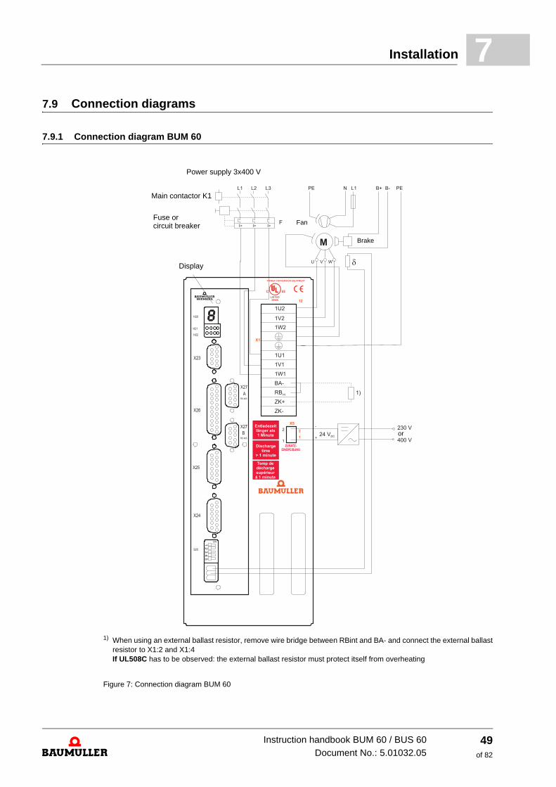
1) When using an external ballast resistor, remove wire bridge between RBint and BA- and connect the external ballast resistor to X1:2 and X1:4 If UL508C has to be observed: the external ballast resistor must protect itself from overheating
Figure 7: Connection diagram BUM 60
Instruction handbook BUM 60 / BUS 60Document No.: 5.01032.05
Controller Refer to separate operation manual controller
K1 Main contactor with auxiliary contact for controller enable
DANGER!Risk of fatal injury from electrical current!A controller enable on the controller may not be issued until the DC link capacitors have been completely charged, i.e. 1 s at the earliest after switching on the main con-tactor.
F Circuit breaker according to VDE 0100, slow blow fuse, 2...2.3 times the rated current or motor circuit breaker matched to the power requirements of the drive and to the peak switch on current.
1U2, 1V2, 1W2, PE2
Motor connections, cross-section according to VDE 0113/0298. Use shielded cables. For installation, see ZInstallation requirements with regard to EMC– from page 46. Cross-sections: 1,5 mm2 up to 14 A, 2,5 mm2 up to 19 A, 4 mm2 up to 25 A, 6 mm2 above 25 A rated motor current. Observe the assignment to the connections in the terminal box.
1U1, 1V1, 1W1, PE1
Connection to power supply. Cross-section according to VDE 0113/0298. For installation, see ZInstallation requirements with regard to EMC– from page 46.
NOTEOne of the terminals is not connected when single-phase power supply.
RBint Connection of an internal ballast resistor
BA- Connection of a ballast transistor; Connection of an external ballast resistor between ZK+ and BA- If UL508C has to be observed: The external ballast resistor must protect itself from overheating
Instruction handbook BUM 60 / BUS 60Document No.: 5.01032.05
51of 82
Connection information7.10
DANGER!Risk of fatal injury from electrical current!When using an external ballast resistor, you must remove the wire bridge between RBint and BA-. Otherwise, the ballast transistor is overloaded and destroyed.
ZK+, ZK- Connections for DC link
BUM 60: Connections for DC link Discharging the DC Link capacitor takes at least one minute. If necessary, the DC Link can be rapidly discharged via a resistor. Connect an external ballast resistor between ZK+ and BA-.
If UL508C has to be observed: The external ballast resistor must protect itself from overheating.
BUS 60: Connections for DC link power supply
DANGER!Risk of fatal injury from electrical current!Parallel switching several devices via the DC Link connections is not allowed. This overloads the starting current limitation device and destroys it.
NOTEOne of the terminals is not connected when single-phase power supply.
PE Ground switching cabinet
1U2, 1V2, 1W2, PE (connections: 4 mm2 maximum)
1U2, 1V2, 1W2
Motor connections
PE Ground connection motor
ZK+, ZK- (connections: 4 mm2 maximum)
BUM 60: Connections for DC link Discharging the DC Link capacitor takes at least one minute. If necessary, the DC Link can be rapidly discharged via a resistor. Connect an external ballast resistor between ZK+ and BA-.
BUS 60: Connections for DC link power supply
RBint, BA-
With internal ballast bridge With external ballast, refer to ZBlock diagrams– from page 33 and ZConnection diagram BUM 60– on page 49.If UL508C has to be observed: The external ballast resistor must protect itself from overheating.
Instruction handbook BUM 60 / BUS 60Document No.: 5.01032.05
53of 82
Accessories7.12
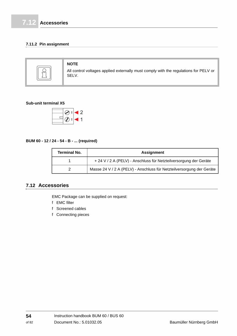
7.11.2 Pin assignment
NOTEAll control voltages applied externally must comply with the regulations for PELV or SELV.
Sub-unit terminal X5
BUM 60 - 12 / 24 - 54 - B - ...
Terminal No. Assignment
1 + 24 V / 2 A (PELV) - Anschluss für Netzteilversorgung der Geräte
2 Masse 24 V / 2 A (PELV) - Anschluss für Netzteilversorgung der Geräte
(required)
7.12 Accessories
EMC Package can be supplied on request:f EMC filterf Screened cablesf Connecting pieces
WARNING!Risk of injury due to improper operation!Improper operation can lead to severe personal injury or material damage.
Therefore:m Perform all operational steps according to the details of these instruction hand-
book.m Before beginning any work, ensure that all coverings and protective devices are
installed and are functioning properly.m The control cabinet in which the device is installed should be protected against
contact with electrically live parts. Keep all doors of the control cabinet closed during operation.
NOTICE!Environmental conditions that do not meet the requirements.Environmental conditions that are non-compliant can lead to property damage.
Therefore:m Ensure that the environmental conditions are kept compliant during operation (see
ZEnvironmental requirements– on page 26).
55of 82
Instruction handbook BUM 60 / BUS 60Document No.: 5.01032.05
Operation8.2
WARNING!Risk of injury due to insufficient qualifications!Inevitably, when operating this electrical device, certain parts of this device are ener-gized with hazardous voltage. Improper handling can lead to significant personal in-jury and material damage.
Therefore:m Only qualified personnel may work on this device!
8.2 Operation
The device is operated using the controller (refer to the description of the controller).
Messages stored in the feed current converter / motor-end inverter can be reset by a reset signal from the controller.
8.3.1 Monitoring facilities of the feed current converter
For the monitoring facilities to function, the 24-V auxiliary voltage (at X5) must be available.
Ballast overload monitoringBallast overload monitoring prevents inadmissibly high loading of the internal brake resistor (ED < 3 %).
Power supply failure / phase failure monitoring (optional)Phase failure monitoring detects a single-phase or three-phase failure of the supply voltage and prevents an internal ready for use. The phase failure monitoring is not activated by default settings. Note derating while single phase operation (see ZElectrical data– from page 27).
NOTEThe message can be reset by a RESET on X1 after 2 s after a renewed connecting of the supply voltage if the 24 V auxiliary voltage or 230 V additional power supply remains. For a normal switch-on a simultaneously switch-on of the power supplies on X1 and X5 is recommended.
8.3.2 Monitoring on motor-end inverter
The following monitoring facilities exist:f Overcurrent in motor linesf Earth-fault currentf DC Link overvoltage f Fault of power transistors (IPM)f Auxiliary power supply
Overcurrent messageThe system monitors the motor current in two motor phases and generates an overcurrent mes-sage if a phase current is 30 % higher than the allowed peak current. This message is saved and results in a pulse disable. The monitoring of 2 phases provides a limited short circuit protection.
The overcurrent message can be reset by a reset signal from the controller. For display and resetting of the message, refer to the description of the controller.
NOTEThe overcurrent message is intended as protection; the controller ensures limitation of the allowed peak current of the motor phase currents.
Instruction handbook BUM 60 / BUS 60Document No.: 5.01032.05
57of 82
Messages and warnings8.3
Earth fault monitoring To detect a motor earth fault the system has a two-phase monitoring of the earth fault current of the motor-end inverter resp. motor phases. An earth fault current error message is generated if the fault current exceeds 10 % of the allowed peak current of the power unit. By this two-phase monitoring the unit is partly earth leakage resistant.
Earth fault monitoring can be reset by a reset signal from the controller. For display and resetting of the message, refer to the description of the controller.
DC link monitoringThe system monitors the level of the DC Link voltage in the motor-end inverter. A message is issued if the DC Link voltage reaches a value that is critical for the power unit.
DC Link monitoring can be reset by a reset signal from the controller. For display and resetting of the message, refer to the description of the controller.
NOTEThe DC Link voltage can rise until switch off if the drive brakes and the ballast power of the ballast circuit on the DC Link is either too small or no ballast circuit exists.
Monitoring power transistorsThe junction region temperature is monitored. The system generates a message if the junction region temperature exceeds 110 °C.
This message can be reset by a reset signal from the controller. For display and resetting of the message, refer to the description of the controller.
Monitoring the auxiliary voltage supplyThe system monitors the auxiliary voltage supply of the power unit and issues a message if an undervoltage occurs.
This message can be reset by a reset signal from the controller. For display and resetting of the message, refer to the description of the controller.
Monitoring the heatsink temperature The power unit does not have its own temperature monitoring facility, since the temperature of the heatsink is not a time-critical variable.
On the heatsink, there is a linear temperature sensor whose measured value is passed on to the controller. This means that the controller carries out temperature monitoring (refer to the de-scription of the controller).
DANGER!Risk of fatal injury from electrical current!Inevitably, when operating this electrical device, certain parts of it are energized with hazardous voltage.
Therefore:m Pay heed to areas on the device that could be dangerous during the electrical in-
stallation.m Pay heed to areas on the device that could still be electrically energized after op-
eration.
WARNING!Risk of injury due to improperly performed maintenance work!Improper maintenance can lead to severe personal injury and material damage.
Therefore:m Before beginning work, make sure that there is enough space for mounting.m Make sure that the mounting area is kept clean and orderly. Parts and tools that
are loosely stacked or lying around are a potential accident source.
59of 82
Instruction handbook BUM 60 / BUS 60Document No.: 5.01032.05
Environmental conditions9.2
9.2 Environmental conditions
If the prescribed environmental conditions are adhered to, then the device is maintenance-free. For the prescribed environmental conditions, see ZEnvironmental requirements– auf Seite 26.
The most important prescribed environmental conditions are:m Dust-free environmental airm Temperature: Min. 5 °C to max. +55 °Cm Relative humidity: 5% to 85%, no condensationm Installation altitude: From 1000 m and higher derating
9.3 Inspection intervals - maintenance notes
Preventive maintenance is prescribed to keep the device in an optimum operating condition and ensure a long service life. It is recommended to have inspections performed regularly by quali-fied personnel.
Daily inspection:
Basic check points as to whether discrepancies have occurred during operation: m Does the motor work as desired?m Is the operating environment normal?m Is the cooling system working normally?m If an unusual vibration or noise is noticed during operation.m Does the motor overheat during operation?
Regularly scheduled inspection:
Before checking, switch off the input voltage and wait until the device's capacitors have dis-charged.
DANGER!Risk of fatal injury from electrical current!Therefore:m Switch off voltage before performing work!m Only qualified personnel may mount, install and maintain the devices. m Please remove all metallic objects worn, such as watches or rings, for example,
before beginning to work on the device. m Only insulated tools are permitted.
DANGER!Risk of fatal injury from electrical current!Stored electric charge.
Discharge time of the system = discharge time of the device with the longest DC link discharge time.
Therefore:m Do not touch electrically live parts before taking into account the discharge time of
the capacitors.m Pay attention to the corresponding notes on the device.m If additional capacitors are connected to the DC link, the DC link discharge can
take a much longer time. In this case, the necessary waiting period must itself be determined or a measurement made as to whether the equipment is de-energized. This discharge time must be posted, together with an IEC 60417-5036 (2002-10) warning symbol, on a clearly visible location of the control cabinet.
9.3.1 Periodic maintenance
m Environmental condition
Check points Methods and criteria Inspection intervals
Daily Semi-annu-ally
Annu-ally
Check environmental temperature, humidity and vibrations.Check whether dust, oil or drops of water appear.
Visual inspection and measurement of the environmen-tal conditions, comparison with standard values.
O
Check whether there are hazardous objects in the vicinity.
Visual inspection O
m Voltage
Check points Methods and criteria Inspection intervals
Daily Semi-annu-ally
Annu-ally
Check the voltage of the power supply system and the control circuits
Measurement and comparison with standard values. O
Instruction handbook BUM 60 / BUS 60Document No.: 5.01032.05
61of 82
Inspection intervals - maintenance notes9.3
m Mechanical parts
Check points Methods and criteria Inspection intervals
Daily Semi-annu-ally
Annu-ally
Are there any abnormal noises or vibrations? Visual and audio check O
Are there any loose screws? Tighten the screws. O
Are there any bent or damaged parts? Visual inspection O
Have there been any color changes due to over-heating?
Visual inspection O
Are there any dust or dirt deposits? Visual inspection O
m Power supply
Check points Methods and criteria Inspection intervals
Daily Semi-annu-ally
Annu-ally
Are there any missing or loose screws? Replace the screws or, respectively, tighten them. O
Is there any deformation, cracking, damage or color change on the device as a result of overheat-ing or aging?
Visual inspection O
Are there any dust or dirt deposits? Visual inspection O
m Connections and circuitry of the mains power supply
Check points Methods and criteria Inspection intervals
Daily Semi-annu-ally
Annu-ally
Does the wiring indicate any color or shape changes due to overheating?
Visual inspection O
Is the wiring insulation damaged or is it discol-ored?
Visual inspection O
Is there any damage? Visual inspection O
m Transformer and chokes in the main circuit
Check points Methods and criteria Inspection intervals
Daily Semi-annu-ally
Annu-ally
Are there any abnormal vibrations or noticeable odors?
In this chapter we describe, how you decommission and store the device.
10.1 Safety instructions
h Refer to ZSafety– from page 11 and the information in ZTransport and Packaging– from page 35.
The shutdown of the device may only be carried out by for this qualified personnel.
DANGER!Risk of fatal injury from electrical current!Stored electric charge.
Discharge time of the system = discharge time of the device with the longest DC link discharge time.
Therefore:m Do not touch electrically live parts before taking into account the discharge time of
the capacitors.m Assure, that all electric connections are current-free and are safe against switch-
on.m Before working, check at the electrical connections with suitable measuring devic-
es, that the connections are off-circuit.m Remove the connections not until the safe isolation from supply has been checked.m If additional capacitors are connected to the DC link, the DC link discharge can
take a much longer time. In this case, the necessary waiting period must itself be determined or a measurement made as to whether the equipment is de-energized. This discharge time must be posted, together with an IEC 60417-5036 (2002-10) warning symbol, on a clearly visible location of the control cabinet.
65of 82
Instruction handbook BUM 60 / BUS 60Document No.: 5.01032.05
Requirements to the executing personnel10.2
10.2 Requirements to the executing personnel
The personnel, who is appointed to setting out of operation, must have the required knowledge and instructions, which is necessary for an execution according to the rules. Select the person-nel in such a way, that the safety instructions, which are mounted to the device and its parts as well as to the connections, are understood and applied to.
10.3 Shutdown
Execute the setting out of operation as follows:1 put the device off-circuit and assure the device against unintentional restart.2 check the isolation from supply of all connections (earliest 10 minutes after switching off).3 demount the connections and protect the connections according to the safety instructions. 4 document the shut down setting.
10.4 Demounting
The demounting assumes a completed, documented setting out of operation.
NOTICE!Note sharp edges.In case, while installing, you lift a device with unprotected hands, fingers/palm can be cut. If the device falls off, your feet can be cut up.
Therefore:
Therefore:m Ensure that only qualified personnel, who are familiar with the safety notes and as-
sembly instructions, demount this device.
Wear safety gloves.
fWear safety shoes.
1 secure the device against falling off/out.2 loosen all mechanical connections.3 lift the device out of the control cabinet.4 store the device in a suitable packing.5 at transportation pay attention to, that the device is not damaged by wrong storage or severe
shocks, also see ZWhat to observe when transporting– on page 35.
In case you want to dispose the device, additional data is available in chapter ZDisposal– from page 69.
The device is maintenance-free. If you keep to the environmental conditions during the entire period of storage, you can assume, that the device will not be damaged. In case the environ-mental conditions during storage are not kept, you should assume that the device is damaged after storage.
CAUTION!Property damage because of incorrect storage conditionsIncorrect storage can damage/destroy the device.
Therefore:
Assure, that the environmental conditions are kept during the entire period of storage:f Climatic category 1K4 f Temperature range -25 °C to +55 °C
CAUTION!Recommissioning without forming of the capacitors. From six months storage period on, the capacitors are destroyed during commission-ing, if they are not formed beforehandf Reform the DC link capacitors:
g by supplying the device ready-to-operate for at least one hour with supply volt-age
g but do not transmit a pulse enable during this time.f Consider, that it is imperative, to connect the accordingly prescribed line commu-
tating reactor for this forming procedure.Devices, where no line commutating reac-tor is necessary can directly be supplied with mains voltage.
Instruction handbook BUM 60 / BUS 60Document No.: 5.01032.05
67of 82
Recommissioning10.6
10.6 Recommissioning
Execute commissioning as with a new device, see ZMounting– from page 37, ZInstallation– from page 43.
CAUTION!Recommissioning without forming of the capacitors. From six months storage period on, the capacitors are destroyed during commission-ing, if they are not formed beforehandf Reform the DC link capacitors:
g by supplying the device ready-to-operate for at least one hour with supply volt-age
g but do not transmit a pulse enable during this time.f Consider, that it is imperative, to connect the accordingly prescribed line commu-
tating reactor for this forming procedure.Devices, where no line commutating reac-tor is necessary can directly be supplied with mains voltage.
NOTEBaumüller products do not belong to the scope of the EU guideline for the disposal of electrical and electronics devices (WEEE, 2002/96/EG). Therefore, no costs are to be carried by Baumüller for the canceling and disposal of old devices.
11.1 Safety notes
DANGER!Risk of fatal injury from electrical current!Stored electric charge.
Discharge time of the system = discharge time of the device with the longest DC link discharge time.
Therefore:m Do not touch electrically live parts before taking into account the discharge time of
the capacitors.m Pay attention to the corresponding notes on the device.m If additional capacitors are connected to the DC link, the DC link discharge can
take a much longer time. In this case, the necessary waiting period must itself be determined or a measurement made as to whether the equipment is de-energized. This discharge time must be posted, together with an IEC 60417-5036 (2002-10) warning symbol, on a clearly visible location of the control cabinet.
69of 82
Instruction handbook BUM 60 / BUS 60Document No.: 5.01032.05
Safety notes11.1
CAUTION!Danger due to sharp edges.If the device is lifted with unprotected hands during deinstallation, palms or fingers can be cut. If the device falls, feet could be injured.
Therefore:m Ensure that only qualified personnel, who are familiar with the safety notes and as-
sembly instructions, mount this device.
Wear safety gloves.
Wear safety shoes.
WARNING!Danger of physical impact!Secure device against falling down.
Therefore:m Take suitable measures, such as supports, hoists and assisting personnel, to en-
sure that device cannot fall down.m Use appropriate means of transport.
NOTICE!Avoid polluting the environment as a result of improper disposal.Therefore:m Only dispose in compliance with the health and safety regulations.m Take heed of any special local regulations. If you are unable to directly ensure safe
disposal yourself, commission a suitable disposal contractor.m In the event of a fire, hazardous substances could possibly be generated or re-
leased.m Do not expose electronic components to high temperatures.m Beryllium oxide is used as inner insulation, for example for various power semicon-
ductors. The beryllium dust that is generated upon opening is injurious to the health. Do not open electronic components.
m Dispose of capacitors, semiconductor modules and electronic scrap as special waste.
WARNING!Danger as a result of faulty deinstallation!The deinstallation and disposal requires qualified personnel with adequate experi-ence.
Therefore:m Only allow deinstallation and disposal to be performed by qualified personnel.
11.2 Disposal facilities/authorities
Ensure that the disposal is handled in compliance with the disposal policies of your company, as well as with all national regulations of the responsible disposal facilities and authorities. In case of doubt, consult the bureau of commerce or environmental protection authority responsi-ble for your company.
Instruction handbook BUM 60 / BUS 60Document No.: 5.01032.05
AC Alternating currentAM Asynchronous motora.m.s.l. above mean sea levelBB Ready for useBUC Baumüller Converter Feed/Feed
Back UnitBUG Baumüller Converter Basic Feed
UnitBUM Baumüller Mono Power UnitBUS Baumüller Power ModuleDC Direct currentDIN Deutsches Institut für Normung
e.V. (German Standardization Authori-ty)
EMC Electromagnetic compatibilityEN European StandardHS Main contactorIPM Intelligent power modulePE Protective earthPELV Protective extra-low voltageRS Controller disableSELV Safe extra-low voltageSM Synchronous motorUZK DC link voltageZK DC link
73of 82
Instruction handbook BUM 60 / BUS 60Document No.: 5.01032.05
Instruction handbook BUM 60 / BUS 60Document No.: 5.01032.05
Declaration of conformityB.1
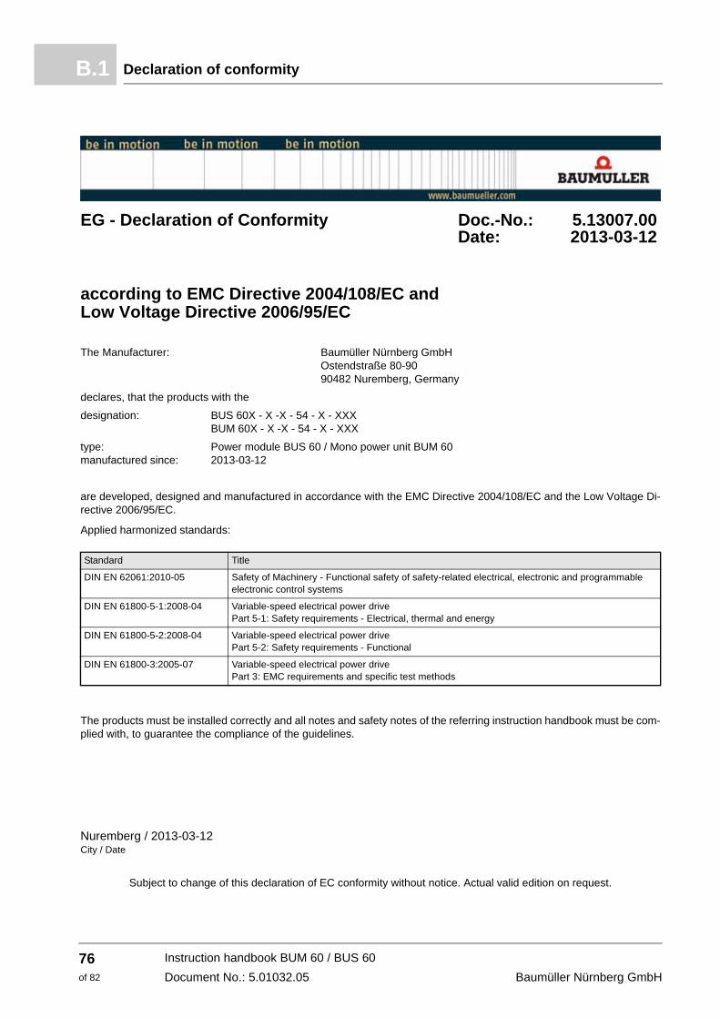
EG - Declaration of Conformity Doc.-No.: 5.13007.00 Date: 2013-03-12
according to EMC Directive 2004/108/EC and Low Voltage Directive 2006/95/EC
The Manufacturer: Baumüller Nürnberg GmbH Ostendstraße 80-90 90482 Nuremberg, Germany
declares, that the products with the
designation: BUS 60X - X -X - 54 - X - XXX BUM 60X - X -X - 54 - X - XXX
type: Power module BUS 60 / Mono power unit BUM 60 manufactured since: 2013-03-12
are developed, designed and manufactured in accordance with the EMC Directive 2004/108/EC and the Low Voltage Di-rective 2006/95/EC.
Applied harmonized standards:
The products must be installed correctly and all notes and safety notes of the referring instruction handbook must be com-plied with, to guarantee the compliance of the guidelines.
Nuremberg / 2013-03-12City / Date
Subject to change of this declaration of EC conformity without notice. Actual valid edition on request.
Standard Title
DIN EN 62061:2010-05 Safety of Machinery - Functional safety of safety-related electrical, electronic and programmable electronic control systems
DIN EN 61800-5-1:2008-04 Variable-speed electrical power drive Part 5-1: Safety requirements - Electrical, thermal and energy
DIN EN 61800-5-2:2008-04 Variable-speed electrical power drive Part 5-2: Safety requirements - Functional
DIN EN 61800-3:2005-07 Variable-speed electrical power drivePart 3: EMC requirements and specific test methods
PPackaging, disposal of 36PE connection 46Personnel, qualified 14Personnel, training 14Protection class 13Protective equipment 15Protective eye wear 15Protective gloves 15Protective work clothing 15
RRecommissioning 68
Instruction handbook BUM 60 / BUS 60Document No.: 5.01032.05
79of 82
80of 82
Index
Repairs 64Residual energy, danger from 16, 44
SSafety 11Safety equipment 18Safety shoes 15Shutdown 65, 66Signs 19Signs and labels 19Spare parts 10Starting current load relief 32Storage 65Storage conditions 67Sub-unit terminal 54Supply system 25
TTechnical data 23Temperature of coolant 41Temperature range 26Terminals 48Transport 35Transport inspection 36Type plate 21
UUnpacking 36Usage, compliant with the intended purpose
12
VVoltage test 45
WWarning 8Warning notes 8Weight 24
Instruction handbook BUM 60 / BUS 60Document No.: 5.01032.05
Baumüller Nürnberg GmbH
Overview of Revisions
Overview of Revisions
Version Status Changes
5.01032.05 18.03.2013 New layout, Chapter overview of revisions added, note for break time after switch-off added,note added: monitoring of 2 lines ensures only limited short circuit protec-tion
Instruction handbook BUM 60 / BUS 60Document No.: 5.01032.05
Alle Angaben in dieser Betriebsanleitung sind unverbindliche Kundeninformationen, unterliegen einer ständigen Weiterentwicklung und werden fortlaufend durch unseren permanentenÄnderungsdienst aktualisiert. Bitte beachten Sie, dass Angaben/Zahlen/Informationen aktuelle Werte zum Druckdatum sind.Zur Ausmessung, Berechnung und Kalkulationen sind diese Angaben nicht rechtlich verbindlich. Bevor Sie in dieser Betriebsanleitung aufgeführte Informationen zur Grundlage eigenerBerechnungen und/oder Verwendungen machen, informieren Sie sich bitte, ob Sie den aktuellsten Stand der Informationen besitzen.Eine Haftung für die Richtigkeit der Informationen wird daher nicht übernommen.