IQ 200 SERIES INSTRUCTIONS FOR INSTALLATION, OPERATION AND MAINTENANCE OF THE CUTLER-HAMMER IQ 200 SERIES OF ELECTRICAL DISTRIBUTION SYSTEM METERS INSTRUCTION LEAFLET TD17558D TD 17558D For more information visit: www .cutler-hammer .eaton.com Effective 2/04
Transcript
IQ 200 SERIESINSTRUCTIONS FOR INSTALLATION,OPERATION AND MAINTENANCE OFTHE CUTLER-HAMMER IQ 200 SERIESOF ELECTRICAL DISTRIBUTIONSYSTEM METERS
INSTRUCTIONLEAFLET
TD17558D
TD 17558DFor more information visit: www.cutler-hammer.eaton.com
Effective 2/04
TD 17558D
Page ii Effective Date: 2/04
IQ 200
Page ii Effective Date: 2/04For more information visit: www.cutler-hammer.eaton.com
Table of ContentsSECTION 1: INTRODUCTION .............................................. 1-1
1.1 PRELIMINARY COMMENTS AND SAFETY PRECAUTIONS1-11.1.1 Warranty and Liability Information ................................... 1-11.1.2 Safety Precautions .......................................................... 1-11.1.3 Factory Correspondence ................................................. 1-2
SECTION 2: HARDWARE DESCRIPTION ........................... 2-12.1 GENERAL ............................................................................................. 2-1
2.1.1 IQ 200 Display Module .................................................... 2-12.1.2 IQ 200 Base Modules ...................................................... 2-12.1.3 Installation ....................................................................... 2-1
2.2 OPERATOR PANEL .............................................................................. 2-32.3 BASE MODULE REAR ACCESS AREA ............................................... 2-3
2.3.1 Current and Voltage Inputs .............................................. 2-42.3.2 Power Supply Input ......................................................... 2-72.3.3 Local Display Connection ................................................ 2-72.3.4 PowerNet Communications (IQ 220 and IQ 230 BaseModule only) ............................................................................. 2-72.3.5 MODBUS Communications ............................................. 2-7
3.2.1 Mounting the IQ 200 Modules as a Single Unit ............... 3-23.2.2 Mounting the IQ 200 Display and Base Modules Separately................................................................................................. 3-2
3.3 WIRING ................................................................................................. 3-43.3.1 Wiring System Current and Voltage ................................ 3-53.3.2 Wiring Diagrams for Various System Configurations ....... 3-53.3.3 PowerNet Communications (IQ 220 and IQ 230 BaseModules Only) ........................................................................ 3-10
Effective Date: 2/04
TD 17558DPage iii
IQ 200
Effective Date: 2/04 Page iiiFor more information visit: www.cutler-hammer.eaton.com
3.3.4 KYZ Pulse Initiator (IQ 220 and IQ 230 Base Modules Only)............................................................................................... 3-10
3.3.5 Inputs and Outputs (IQ 230 and IQ 230M only) ............. 3-12
SECTION 4: OPERATION ..................................................... 4-14.1 GENERAL ............................................................................................. 4-14.2 BUTTONS ............................................................................................. 4-14.3 CONTRAST .......................................................................................... 4-24.4 DISPLAYED SIGN CONVENTIONS ..................................................... 4-24.5 USING THE OPERATOR PANEL ......................................................... 4-34.6 SYSTEM DATA DISPLAY MODE ........................................................ 4-4
4.6.1 3 Wire System and 4 Wire System .................................. 4-44.6.2 System Input (IQ 230 and IQ 230M only) ........................ 4-54.6.3 System Lock (IQ 230 and IQ 230M only) ........................ 4-5
4.7 PHASE DATA DISPLAY MODE ............................................................ 4-54.7.1 3 Wire System ................................................................. 4-54.7.2 4 Wire System ................................................................. 4-7
4.8 MIN/MAX DATA DISPLAY MODE ......................................................... 4-74.8.1 3 Wire System ................................................................. 4-74.8.2 4 Wire System ................................................................. 4-7
4.9 VIEW SET POINTS (3 and 4 wire systems) ....................................... 4-84.9.1 View All ............................................................................ 4-84.9.2 Password Setup .............................................................. 4-84.9.3 .... INCOM™ Setup (IQ 220 and IQ 230 Base Modules only)................................................................................................. 4-9
4.9.4 MODBUS™ Setup (IQ 230M Base Modules only) .......... 4-94.9.5 System Frequency ........................................................ 4-104.9.6 Wiring Configuration ...................................................... 4-104.9.7 CT Ratio ........................................................................ 4-104.9.8 PT Ratio ........................................................................ 4-104.9.9 Demand Window ........................................................... 4-114.9.10 KYZ Setup (IQ 220 and IQ 230 Base Module only) ..... 4-114.9.11 Digital Output Setup (IQ 230 & IQ 230M Base ModuleOnly) ....................................................................................... 4-114.9.12 Exit .............................................................................. 4-12
4.10 EDIT Set Points (3 and 4 wire systems) ......................................... 4-124.10.1 Edit All ......................................................................... 4-124.10.2 Password Setup .......................................................... 4-134.10.3 .. INCOM™ Setup (IQ 220 and IQ 230 Base Modules only)............................................................................................... 4-13
4.10.4 MODBUS™ Setup (IQ 230M Base Module only) ........ 4-144.10.5 System Frequency ...................................................... 4-144.10.6 Wiring Configuration .................................................... 4-15
TD 17558D
Page iv Effective Date: 2/04
IQ 200
Page iv Effective Date: 2/04For more information visit: www.cutler-hammer.eaton.com
4.10.7 CT Ratio ...................................................................... 4-154.10.8 PT Ratio ...................................................................... 4-164.10.9 Demand Window ......................................................... 4-164.10.10 KYZ Setup (IQ 220 and IQ 230 Base Modules Only) ...................................................................................................... 4-17
4.10.11 Digital Output Setup (IQ 230 & IQ 230M Base ModuleOnly) ....................................................................................... 4-184.10.12 Message to Outputs A1 and A2 (IQ 230 & IQ 230M BaseModule Only) .......................................................................... 4-184.10.13 Exit ............................................................................ 4-19
SECTION 5: NETWORK COMMUNICATION PROTOCOLS 5-15.1 MODBUS RS485 NETWORK............................................................... 5-15.2 OVERVIEW ........................................................................................... 5-15.3 FUNCTION CODES .............................................................................. 5-35.4 BLOCK OF REGISTER ........................................................................ 5-35.5 UNDERSTANDING ADDRESS 1800 AND 1801 .................................. 5-55.6 EXTENDED COMMUNICATIONS VIA MODBUS ................................ 5-65.7 COMMAND DATA PASS THROUGH ................................................... 5-85.8 MODBUS EXCEPTION CODES......................................................... 5-16
SECTION 6: TROUBLESHOOTING AND MAINTENANCE . 6-16.1 GENERAL ............................................................................................. 6-1
6.1.1 Level of Repair ................................................................ 6-16.1.2 Maintenance and Care .................................................... 6-1
6.2 REMOVAL AND REPLACEMENT ........................................................ 6-16.2.1 General Safety Precautions............................................. 6-26.2.2 IQ 200 Base Module ........................................................ 6-26.2.3 IQ 200 Display Module .................................................... 6-2
6.3 GENERAL TROUBLESHOOTING PROCEDURES ............................. 6-36.4 TECHNICAL ASSISTANCE .................................................................. 6-5
Effective Date: 2/04
TD 17558DPage 1-1
IQ 200
Effective Date: 2/04 Page 1-1For more information visit: www.cutler-hammer.eaton.com
CAUTION
SECTION 1: INTRODUCTION
1.1 PRELIMINARY COMMENTS AND SAFETY PRECAUTIONSThis Technical Document covers most aspects of installation, operation, and unit-level maintenance of the IQ 200. This document is a guide only for authorized andqualified personnel who select and use the IQ 200. Please refer to the specificWARNING and CAUTION in this section before proceeding. If you require furtherinformation regarding a particular installation, application or maintenance activity,contact your Cutler-Hammer representative.
1.1.1 Warranty and Liability InformationNo warranties, expressed or implied, including warranties of fitness for a particularpurpose of merchantability, or warranties arising from course of dealing or usage oftrade are made regarding this information, recommendations, and descriptionscontained herein.
1.1.2 Safety PrecautionsAll safety codes, safety standards, and/or regulations must be strictly observed in theinstallation, operation, and maintenance of this device.
THE WARNINGS AND CAUTIONS INCLUDED AS PART OF THEPROCEDURAL STEPS IN THIS DOCUMENT ARE FOR PERSONNELSAFETY AND PROTECTION OF EQUIPMENT FROM DAMAGE. ANEXAMPLE OF A TYPICAL CAUTION LABEL IS SHOWN ABOVE. THISWILL HELP TO ENSURE THAT PERSONNEL ARE ALERT TO WARNINGSWHICH MAY APPEAR THROUGHOUT THE DOCUMENT.
COMPLETELY READ AND UNDERSTAND THE MATERIAL PRESENTEDIN THIS DOCUMENT BEFORE ATTEMPTING TO INSTALL, OPERATE ORUSE THE EQUIPMENT. IN ADDITION, ONLY QUALIFIED PERSONSSHOULD BE PERMITTED TO PERFORM ANY WORK ASSOCIATED WITH
WARNING
TD 17558D
Page 1-2 Effective Date: 2/04
IQ 200
Page 1-2 Effective Date: 2/04For more information visit: www.cutler-hammer.eaton.com
THE EQUIPMENT. ANY WIRING INSTRUCTIONS PRESENTED IN THISDOCUMENT MUST BE FOLLOWED PRECISELY. FAILURE TO DO SOCOULD CAUSE PERMANENT EQUIPMENT DAMAGE.
1.1.3 Factory CorrespondenceFor additional information, technical assistance or referral to a local authorizeddistributor, contact Power Management Application Support (PMAS) at 1-800-809-2772, option 1 / option 1.
1.2 PRODUCT OVERVIEWNOTE: Throughout this document, references to IQ 200 are intended for all Basetypes in the series, the IQ 210, IQ 220, IQ 230 and the IQ 230M. Units withfunctions and specifications that differentiate from the Base Unit are noted in therelevant sections.The IQ 200 is a microprocessor based series of monitoring devices that providesingle phase, 2 or 3 wire, and 3 phase, 3 or 4 wire electrical metering designed toreplace numerous individual meters and recorders. The IQ 200 series devices arecompact, and consist of a panel-mounted Display Module and a Base Module thatcan be attached to the Display Module or mounted remotely. The devices arepassword protected, menu driven and display a variety of user-selected electricalsystem values and provide control over certain measurement and data outputfunctions. The IQ 200 series Base Modules communicate with the IQ 200 DisplayModule, providing access to view and reset system, phase and min/max values, andfor providing viewing and editing of set points.
3 Phase 3 Phase 3 Phase Single Phase 4 Wire 3 Wire 3 or 4 Wire 2 or 3 Wire
Effective Date: 2/04 Page 1-3For more information visit: www.cutler-hammer.eaton.com
The IQ 200 series includes four variations of the IQ 200 Base Module and a singleIQ 200 Display Module that functions with any Base type. The IQ 210 Base Moduleis a reduced function variation, while the IQ 220, the IQ 230 and the IQ 230M BaseModules have additional capabilities.The IQ 220 includes a wider ranging power supply, PowerNet communication, byway of the INCOM port, which provides information to the network master deviceand a KYZ Pulse output proportional to the energy consumed by the system beingmonitored.
IQ200 Series Features:
The IQ 230 includes a wider ranging power supply, PowerNet communication, byway of the INCOM port, which provides information to the network master device, aKYZ Pulse output proportional to the energy consumed by the system beingmonitored, 2 digital outputs (form A contacts), 2 digital inputs, that read and counttransitional edges (that occur as often as 8ms) and 1 analog input to read 4 to 20ma signal and display a percentage of 0 to 100.While the IQ 230M includes everything the IQ 230 Base Module includes, theINCOM communication is replaced with MODBUS.
Meter Model
Display Size
(in inches)Pow er Supply Comm
KYZ Output
Digital Inputs
Digital Outputs
Analog Input
Utility Sealing
IQ210 4.38x4.38110-240 Vac 125-250 Vdc NO NO NO NO NO NO
IQ220 4.38x4.3890-600 Vac 48-250 Vdc INCOM YES NO NO NO NO
Page 1-4 Effective Date: 2/04For more information visit: www.cutler-hammer.eaton.com
ValuesDisplayed
System Each Phase Minimum/MaximumPower Current CurrentsFrequency Current Demand Line to Line VoltagesApparent PowerFactor
Current PeakDemand
Line to Neutral Voltages
Displacement PowerFactor
Line to Line Voltage System Power(W, vars, VA)
Watt Hours Line to NeutralVoltage
System Frequency
var Hours Watts System ApparentPower Factor
VA Hours vars System DisplacementPower Factor
Demand (W, var, VA) VAPeak Demand(W, var, VA)
Apparent PowerFactorDisplacement PowerFactor
The IQ 200 displays the following values:
Effective Date: 2/04
TD 17558DPage 2-1
IQ 200
Effective Date: 2/04 Page 2-1For more information visit: www.cutler-hammer.eaton.com
SECTION 2: HARDWARE DESCRIPTION
2.1 GENERALThis section describes the IQ 200 hardware, its functions and nomenclature, andlists the IQ 200 specifications. An IQ 200 consists of two components, the DisplayModule, figure 2.1, and a Base Module, figure 2.2.Do not attempt to disassemble or open the case of either the IQ 200 Display Moduleor the IQ 200 Base Modules (IQ 210, IQ 220 or IQ 230). The units contain no user-serviceable components.
2.1.1 IQ 200 Display ModuleThe Display Module screenpresents system values andfunctions. The Menu, up/downScroll, and Enter buttons allow theoperator to view, change, andreset system parameters. The portfor connecting to an IQ 200 BaseModule (IQ 210, IQ 220, IQ 230 orIQ 230M) is located on the backside of the IQ 200 Display Module.
2.1.2 IQ 200 Base ModulesThe IQ 200 Base Modules
measure system values and provide metering data. Current and voltage inputterminals, power supply terminals and the display port are all located on the rearface of the IQ 200 Base Modules. On the IQ 220 and IQ 230 an additional I/O isprovided by way of a KYZ pulse output. Two contact outputs, two digital inputs, oneanalog input, an INCOM™ communications port and an INCOM™ transmit indicatorLED are provided on the IQ 230. A MODBUS™ communications port is providedon the IQ 230M.The IQ 230 and IQ 230M also provide lock out features for certain programmingsetpoints and reset values. This lock out feature will not allow a user to changethese settings until the lock out feature is turned off. See Section 4.6.4 for additionalinformation about the lock out feature.
2.1.3 InstallationThe IQ 200 is usually mounted inside an environmentally suitable electricalswitch-gear enclosure. The IQ 200 Display Unit and the IQ 200 Base Module can bemounted together or separately in a variety of ways, described fully in SECTION 3:INSTALLATION.
Figure 2.1 IQ 200 Display Module
TD 17558D
Page 2-2 Effective Date: 2/04
IQ 200
Page 2-2 Effective Date: 2/04For more information visit: www.cutler-hammer.eaton.com
Figure 2.2 IQ 220 Base Module
Figure 2.2 IQ 230 Base Module
Figure 2.2 IQ 210 Base Module
Effective Date: 2/04
TD 17558DPage 2-3
IQ 200
Effective Date: 2/04 Page 2-3For more information visit: www.cutler-hammer.eaton.com
2.2 OPERATOR PANELThe Operator Panel is the front face of theIQ 200 Display Module. It is usuallyinstalled so that it is visible and accessiblefrom the outside of the panel or door intowhich it is mounted.The Menu, up/down Scroll and Enterbuttons allow the operator to view, changeand reset various system parameters.• Display measured system, phase andmin/max values• View and edit all or individual set points:
– Password– INCOM™ network address andbaud rate (IQ 220 and IQ 230 only)– MODBUS™ network addressand baud rate (IQ 230M only)– System frequency– Wiring configuration– Ct and Pt ratios– Demand window– Energy tracking (KYZ pulse output) - (IQ 220 and IQ 230 only)– Digital Output Setup (IQ 230 only)
• View energy, view and reset peak demands, and all or individual minimum andmaximum values.• Change the display contrast for best viewing
The Operator Panel is an integral part of the IQ 200 Display Module. Do not attemptto remove it from the IQ 200 Display Module.
2.3 BASE MODULE REAR ACCESS AREAAll wiring connections are made from the rear face of the chassis, shown infigure 2.4a, 2.4b and 2.4c.The current transformer terminal block is located at the top rear of the chassis. TheIQ 210 and the IQ 220 each have 6 terminals, grouped in 3 pairs: one pair for eachphase current transformer, see Figure 2.4a and 2.4b.The IQ 230 has twelve terminals, grouped into six pairs: one pair for each phasecurrent transformer, as shown below, and one pair for each of the two digital inputsand the one analog input.Note: For sections 2.3.1 through 2.3.4 refer to figures 2.4c, 2.4d and 2.4e.
Figure 2.3 Operator Panel
TD 17558D
Page 2-4 Effective Date: 2/04
IQ 200
Page 2-4 Effective Date: 2/04For more information visit: www.cutler-hammer.eaton.com
2.3.1 Current and Voltage InputsThe voltage terminal block is located at the bottom rear of the chassis. It has fourterminals for wiring the phase voltages and the neutral, as shown in Figure 2.5. Theneutral terminal must be connected to system neutral or ground depending onsystem configuration. All connections must be made in accordance with nationaland local requirements and codes.
Figure 2.4a IQ 210 Rear Face View
System Voltage Input Neutral Power Supply
Ground Lug
Connector to IQ 200 Display Module
System Current Transformer Input
System Voltage Input Neutral Power Supply
Ground Lug
Connector to IQ 200 Display Module
System Current Transformer Input
Figure 2.4b IQ 220 Rear Face View
System Voltage Input Neutral Power Supply
Ground Lug
Connector to IQ 200 Display Module
System Current Trans former Input
Communication Transmit LED
INCOM Port
K-Y-Z Pulse Output
System Voltage Input Neutral Power Supply
Ground Lug
Connector to IQ 200 Display Module
System Current Trans former Input
Communication Transmit LED
INCOM Port
K-Y-Z Pulse Output
Effective Date: 2/04
TD 17558DPage 2-5
IQ 200
Effective Date: 2/04 Page 2-5For more information visit: www.cutler-hammer.eaton.com
Figure 2.4c IQ 230 Rear Face View
1
A2
A
HIN2IN1 AN1
DISPLAY
R
TXA1
1 2 1
I IR R I
NEUVBVA VC PS1 PS2
1 212 2
MOD2
INCOM1
PULSEY2 K Z 32 1
BA B C C
HH H H H
Connector to Display
Communication Transmit LED
Ground Lug
System Voltage Input
Power Supply
Neutral
1
A2
A
HIN2IN1 AN1
DISPLAY
R
TXA1
1 2 1
I IR R I
NEUVBVA VC PS1 PS2
1 212 2
MOD2
INCOM1
PULSEY2 K Z 32 1
BA B C C
HH H H H
Connector to Display
Communication Transmit LED
Ground Lug
System Voltage Input
Power Supply
Neutral
Figure 2.4d IQ 230 Rear Face Views (continued)
1
A2
A
HIN2IN1 AN1
DISPLAY
R
TXA1
1 2 1
I IR R I
NEUVBVA VC PS1 PS2
1 212 2
MOD2
INCOM1
PULSEY2 K Z 32 1
BA B C C
HH H H H
Digital Input 1I = Input
R = Return
CT Lines for Phase A
CT Lines for Phase B
CT Lines for Phase C
Digital Input 2I = Input
R = Return
Analog InputI = Input
R = Return
1
A2
A
HIN2IN1 AN1
DISPLAY
R
TXA1
1 2 1
I IR R I
NEUVBVA VC PS1 PS2
1 212 2
MOD2
INCOM1
PULSEY2 K Z 32 1
BA B C C
HH H H H
Digital Input 1I = Input
R = Return
CT Lines for Phase A
CT Lines for Phase B
CT Lines for Phase C
Digital Input 2I = Input
R = Return
Analog InputI = Input
R = Return
CT Lines for Phase C
Digital Input 2I = Input
R = Return
Analog InputI = Input
R = Return
WARNINGTHIS TERMINAL BLOCK MUST NEVER BE REMOVED WHILE THE UNITIS ENERGIZED. PERSONAL INJURY AND / OR EQUIPMENT DAMAGEMAY RESULT.
TD 17558D
Page 2-6 Effective Date: 2/04
IQ 200
Page 2-6 Effective Date: 2/04For more information visit: www.cutler-hammer.eaton.com
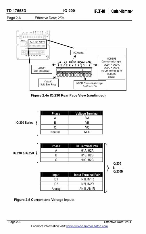
Figure 2.4e IQ 230 Rear Face View (continued)
1
A2
A
HIN2IN1 AN1
DISPLAY
R
TXA1
1 2 1
I IR R I
NEUVBVA VC PS1 PS2
1 212 2
MOD2
INCOM1
PULSEY2 K Z 32 1
BA B C C
HH H H H
Output 1Solid State Relay
Output 2Solid State Relay
KYZ Output
INCOM Communication Input 3 = Ground Pin
MODBUSCommunication Input
MOD 1 = MOD AMOD 2 = MOD B
INCOM 3 should be forMODBUS
ground
Figure 2.5 Current and Voltage Inputs
Phase Voltage Terminal A VA B VB C VC
Neutral NEU
Phase CT Terminal Pair A H1A, H2A B H1B, H2B C H1C, H2C
Effective Date: 2/04 Page 2-7For more information visit: www.cutler-hammer.eaton.com
2.3.2 Power Supply InputThe IQ 200 power supply input is connected to the PS1 and PS2 terminals on thelower right rear of the Base Module chassis. The IQ 210 Base version requires 110to 240 Vac or 125 to 250 Vdc. The IQ 220 and IQ 230 Base versions have a wideroperating power supply input range in comparison to the IQ 210 version. The IQ220 and the IQ 230 power supply can accommodate 90 to 600 VAC or 48 to 250Vdc. The power supply may be directly wired to the monitored system, if the voltageis within the proper range.
2.3.3 Local Display ConnectionThe supplied Category 5 cable connects to the DISPLAY port located on the leftrear of the chassis and to the port on the IQ 200 Display Module. Do not route theCategory 5 cable in the same enclosure or cable tray as 600 V system wiring.Maximum certified cable length is 10 feet.
2.3.4 PowerNet Communications (IQ 220 and IQ 230 Base Moduleonly)The IQ 220 and IQ 230 Electrical Distribution System Meter is a PowerNet compat-ible device. When connected to a PowerNet System, via the INCOM port, it can beremotely monitored and functionally modified.PowerNet enables efficient monitoring, trending and alarm indication for electricaldistribution system equipment. PowerNet is a noise-immune communication systemthat permits communication between a master computer and system devices, suchas the IQ 220 and the IQ 230.Consult TD17513 IMPACC Wiring Specification Base Rules for detailed informationon proper installation and termination of network cable.The following functions can be performed remotely when the IQ 220 or IQ 230 isconnected to an external PowerNet compatible network:• Display measured system, phase and min/max values• View and edit set points
– System frequency– Wiring configuration– CT and PT ratios– Demand window– Energy tracking (KYZ pulse output)
• View energy, view and reset peak demands, and all or individual minimum andmaximum values.• View status or count of the 2 digital inputs, reset digital outputs and read analoginput (IQ 230 ONLY).
2.3.5 MODBUS CommunicationsThe IQ 230M Enhanced Electrical Distribution System Meter is a MODBUScompatible device. When connected via the MODBUS port, values can be remotely
TD 17558D
Page 2-8 Effective Date: 2/04
IQ 200
Page 2-8 Effective Date: 2/04For more information visit: www.cutler-hammer.eaton.com
read using the addresses provided in the MODBUS table. Further capabilities canbe obtained through the use of INCOM PASSTHRU and SLAVE ACTION tech-niques explained in chapter 5.
2.4 EXTERNAL HARDWARE
2.4.1 Current TransformersThe IQ 200 series requires at least two user-supplied external instrument classcurrent transformers with 5 amp secondaries. These transformers must be con-nected to the current transformer terminals on the IQ 200 Base Module as detailedin section 3.3.
2.4.2 Potential TransformersThe IQ 200 series requires user-supplied potential transformers if the system linevoltage is above 600 volts. These transformers must be connected to the voltageterminals on the IQ 200 Base Module as detailed in section 3.3.
2.4.3 External FusesIt is recommended that user-supplied fuses be installed as described below toprotect the IQ 200 and related components from damage.2.4.3.1 Fusing IQ 200 Power Supply
External fuses should be installed in the IQ 200 power supply lines, near the IQ 200Base Module. 600 volt ½ Ampere BUSS type KTK-R-1/2 Fast Acting or equivalentfuses are recommended for the IQ 200 Base PS1 and PS2 power supply lines.2.4.3.2 Fusing Potential Transformers
External fuses should be installed in the potential transformer lines as specified inthe National Electric Code for the specific application.
2.5 PRODUCT SPECIFICATIONSRefer to tables 2.1 through 2.5 for all IQ 200 specifications.
2.5.1 Regulatory/Standards ComplianceThe IQ 200 series meets UL, CSA and CE requirements.
Effective Date: 2/04
TD 17558DPage 2-9
IQ 200
Effective Date: 2/04 Page 2-9For more information visit: www.cutler-hammer.eaton.com
Effective Date: 2/04 Page 2-11For more information visit: www.cutler-hammer.eaton.com
ANSI C12 Note: The IQ 200 has been designed and verified to meet ANSI C12Class 10 Revenue metering accuracy. This classification makes the IQ 200 an idealchoice for sub-metering and sub-billing applications.
Parameter AccuracyCurrent (< 5 amps) ± .5% of Full ScaleCurrent (> 5 amps) ± .5% of ReadingVoltage, line-to-line ± .5% of Full ScaleVoltage, line-to-neutral ± .5% of Full ScaleWatts (< 5 amps) ± 1% of Full ScaleWatts (> 5 amps) ± 1% of Readingvars (< 5 amps) ± 1% of Full Scalevars (> 5 amps) ± 1% of ReadingVA (< 5 amps) ± 1% of Full ScaleVA (> 5 amps) ± 1% of ReadingPower Factor ± 2% of Full ScaleFrequency ± 0.1 Hz
Table 2.3 IQ 200 Metering Accuracy
Control Power Input Range
IQ 210 Base IQ 220 Base IQ 230 Base
110-240 Vac±10% 90-600 Vac±10% 90-600 Vac±10%
125-250 Vdc±10% 48-250 Vdc±10% 48-250 Vdc±10%
Frequency Range 50/60 Hz — Burden
IQ 210 Base IQ 220 Base IQ 230 Base
7 W
180 mA 200 mA
7 W 7 W 8 W
Table 2.2 IQ 200 Operating Specifications (cont.)
TD 17558D
Page 2-12 Effective Date: 2/04
IQ 200
Page 2-12 Effective Date: 2/04For more information visit: www.cutler-hammer.eaton.com
Dimension Display Module Base ModuleLength 1.38 in.(1) 6.74 in.(2)
Height 4.38 in. 3.56 in.(3)
Width 4.38 in. 3.56 in.Base Unit TerminalsWire Size #12-22 AWGScrew Size #6-32Torque Rating 9 in.-lbs. MaximumDistance Between Barriers 0.32 in.WeightDisplay Module 0.56 lbs.Base Module 2.35 lbs.1. includes 0.58 in. rear cover2. includes 0.06 in. front face mounting plate and 0.62 in. terminal block3. centered on front face mounting plate
Table 2.5 IQ 210 and IQ 220 Physical Characteristics
Parameter Max Data RangeCurrent 0…65,535 ampsVoltage 0…2,097,120 voltsPower
WattsvarsVA
-1,073,709,057…+1,073,709,056 Watts-1,073,709,057…+1,073,709,056 vars0…2,147,450,880 VA
Effective Date: 2/04 Page 2-13For more information visit: www.cutler-hammer.eaton.com
IQ 230 Physical Characteristics
1
A2
A
HIN2IN1 AN1
DISPLAY
R
TXA1
1 2 1
I IR R I
NEUVBVA VC PS1 PS2
1 212 2
MOD2
INCOM1
PULSEY2 K Z 32 1
BA B C C
HH H H H
Dimension Display Module Base ModuleLength 1.38 in.(1) 6.74 in.(2)
Height 4.38 in. 3.56 in.(3)
Width 4.38 in. 3.56 in.WeightDisplay Module 0.56 lbs.Base Module 2.35 lbs.(1) includes 0.58 in. rear cover(2) includes 0.06 in. front face mounting plate and 0.62 in. terminal block(3) centered on front face mounting plate
Base Unit TerminalsWire Size #24-12 AWGTorque Rating .5 - .6 NmBase Unit TerminalsWire Size #16-28 AWGTorque Rating .22 - .25 Nm
Base Unit TerminalsWire Size #12-22 AWGScrew Size #6-32Torque Rating 9 in.-lbs. MaximumDistance Between Barriers 0.32 in.
TD 17558D
Page 2-14 Effective Date: 2/04
IQ 200
Page 2-14 Effective Date: 2/04For more information visit: www.cutler-hammer.eaton.com
2.6 ORDERING INFORMATIONPlease refer to the Catalog Number listed in the following table when ordering IQ200 components.
Table 2.6 IQ 200 Ordering Information
Description Catalog Number IQ 210 Base Module IQ210TRAN IQ 220 Base Module IQ220TRAN IQ 230 Base Module IQ230TRAN IQ 230 MODBUS Base Module IQ230MTRAN IQ 200 Series Display Module IQ200D IQ 210 Complete Meter with Base Module & IQ 200 Display Module & 36” Cable
IQ210
IQ 220 Complete Meter with Base Module & IQ 200 Display Module & 36” Cable
IQ220
IQ 230 Complete Meter with Base Module & IQ 200 Display Module & 36” Cable
IQ230
IQ 230 MODBUS Complete Meter with Base Module & IQ 200 Display & 36” Cable
IQ230M
3 foot long Category 5 Cable IQ23CABLE 6 foot long Category 5 Cable IQ26CABLE 10 foot long Category Cable IQ210CABLE IQ 210 Base Module IQ 220 Base Module
IQ 230 Base Module IQ230M Base
Module (1) IQ 210 Base (1) DIN Rail Clip (1) L-Bracket (4) ½” #10 (10-32) screws (4) #10 Locking Washers (2) ¼” #8 (8-32) screws
(1) IQ 220 Base (1) DIN Rail Clip (1) L-Bracket (4) ½” #10 (10-32) screws (4) #10 Locking Washers (2) ¼” #8 (8-32) screws
(1) IQ 230 Base (1) DIN Rail Clip (1) L-Bracket (4) ½” #10 (10-32) screws (4) #10 Locking Washers (2) ¼” #8 (8-32) screws (2) Plug-in Contacts
Effective Date: 2/04
TD 17558D
Page 3-1
IQ 200
Effective Date: 2/04 Page 3-1For more information visit: www.cutler-hammer.eaton.com
SECTION 3: INSTALLATION
3.1 INTRODUCTIONThe IQ 200 is designed to be installed, operated and maintained by adequatelytrained personnel. These instructions do not cover all details, variations or combina-tions of the equipment, its storage, delivery, installation, checkout, safe operation ormaintenance. Care must be exercised to comply with local, state and nationalregulations, as well as with industry standard safety practices for this class ofequipment. Refer to figure 3.5 through 3.14 for wiring details.
A THREE PHASE SWITCH OR CIRCUIT BREAKER SHOULD BE INCLOSE PROXIMITY TO THE IQ 200 MOUNTING LOCATION ANDMARKED AS THE DISCONNECTING DEVICE FOR THE EQUIPMENT.ADDITIONALLY, IT IS RECOMMENDED THAT CT SHORTING TERMINALBLOCKS BE USED IN ORDER TO FACILITATE ANY FUTUREMAINTENANCE OR REMOVAL OF THE IQ 200 BASE MODULE.
TURN OFF AND LOCK OUT POWER SUPPLYING THE PANEL BOARDOR SWITCH GEAR IN WHICH THE IQ 200 IS BEING INSTALLED.FAILURE TO DO SO CAN RESULT IN INJURY TO PERSONNEL ORDAMAGE TO EQUIPMENT.
3.2 PANEL PREPARATIONIt is recommended that the IQ 200 be mounted in an electrical switch gear enclo-sure that is suitable for its environment. The IQ 200 Display and IQ 200 BaseModules may be mounted together or separately. The IQ 200 is designed withflexibility in mind. While it is recommended that the IQ 200 Display Module be door-or panel-mounted, the Base Module may be attached to the IQ 200 Display Module;mounted remotely using the supplied L-bracket; directly to a panel or floor; orattached to a DIN rail using the supplied DIN clip. For floor or panel mounting, a #10(10-32) or #12 (12-28) screw is recommended.In all instances where the IQ 200 Base Module is mounted remotely, the IQ 200Display Module Chassis must be connected to earth ground.Before installing the IQ 200, refer to dimensions listed in table 2.5 and allow ad-equate room for wiring and access to the IQ 200 Base Module terminals and
WARNING
WARNING
TD 17558D
Page 3-2 Effective Date: 2/04
IQ 200
Page 3-2 Effective Date: 2/04For more information visit: www.cutler-hammer.eaton.com
IQ 200 Display Module
Gasket
Panel
Mounting Bracket
Locking Washer
Hex Nut
OR
100mmANSICutout
1/4 DINCutout
Figure 3.1 Securing the IQ 200 DisplayModule
Figure 3.2 Mounting the IQ 200 BaseModule to the IQ 200 Diplay Module
IQ 230 D isp lay M odule– mounted in a pane l
IQ 230 Base M odule
Locking W asher
#10 Screw
1
A2
A
HIN2IN1 AN1
DISPLAY
R
TXA1
1 2 1
I IR R I
NEUVBVA VC PS1 PS2
1 212 2
MO D2
INCOM1
PULSEY2 K Z 32 1
BA B C C
HH H H H
connectors.
3.2.1 Mounting the IQ 200 Modules as a Single UnitCut a ¼ DIN (92mm x 92mm) access cutout in the switch gear door or other panelwhere the IQ 200 is to be mounted as shown in figure 3.1. (Additionally a 100mmcircular ANSI cutout is suitable.) Install the IQ 200 Display Module following thesesteps:• Slide the supplied gasket over therear of the IQ 200 Display Moduleand mounting studs until it is flushwith the rear of the back cover.• Insert the IQ 200 Display Modulewith gasket installed into the cutout.• Insert one end of the Category 5cable into the port on the rear of theDisplay Module.• From the inside of the panel, slidethe 2 brackets over the mountingstuds protruding through the cutout,capturing the panel and gasketbetween the Display Module andmounting brackets.• Secure the brackets and displayunit, with the gasket and panelbetween, using the four supplied #8locking washers and hex nuts.• Attach the IQ 200 Base Module to the brackets using the supplied #10 screws
and locking washers, as shownin figure 3.2.
Connect the IQ 200 DisplayModule to the IQ 200 BaseModule by inserting the remain-ing end of the Category 5 cableinto the DISPLAY port on the IQ200 Base Module. Do not routethe Category 5 cable in thesame enclosure or cable tray as600V system wiring.Proceed to section 3.3 Wiring.
3.2.2 Mounting the IQ 200
Effective Date: 2/04
TD 17558D
Page 3-3
IQ 200
Effective Date: 2/04 Page 3-3For more information visit: www.cutler-hammer.eaton.com
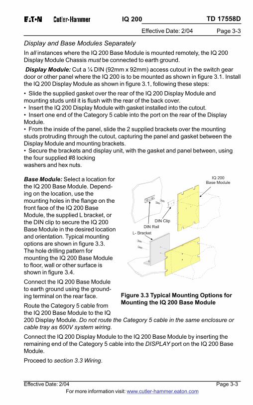
Display and Base Modules SeparatelyIn all instances where the IQ 200 Base Module is mounted remotely, the IQ 200Display Module Chassis must be connected to earth ground. Display Module: Cut a ¼ DIN (92mm x 92mm) access cutout in the switch geardoor or other panel where the IQ 200 is to be mounted as shown in figure 3.1. Installthe IQ 200 Display Module as shown in figure 3.1, following these steps:• Slide the supplied gasket over the rear of the IQ 200 Display Module andmounting studs until it is flush with the rear of the back cover.• Insert the IQ 200 Display Module with gasket installed into the cutout.• Insert one end of the Category 5 cable into the port on the rear of the DisplayModule.• From the inside of the panel, slide the 2 supplied brackets over the mountingstuds protruding through the cutout, capturing the panel and gasket between theDisplay Module and mounting brackets.• Secure the brackets and display unit, with the gasket and panel between, usingthe four supplied #8 lockingwashers and hex nuts.
Base Module: Select a location forthe IQ 200 Base Module. Depend-ing on the location, use themounting holes in the flange on thefront face of the IQ 200 BaseModule, the supplied L bracket, orthe DIN clip to secure the IQ 200Base Module in the desired locationand orientation. Typical mountingoptions are shown in figure 3.3.The hole drilling pattern formounting the IQ 200 Base Moduleto floor, wall or other surface isshown in figure 3.4.Connect the IQ 200 Base Moduleto earth ground using the ground-ing terminal on the rear face.Route the Category 5 cable fromthe IQ 200 Base Module to the IQ200 Display Module. Do not route the Category 5 cable in the same enclosure orcable tray as 600V system wiring.Connect the IQ 200 Display Module to the IQ 200 Base Module by inserting theremaining end of the Category 5 cable into the DISPLAY port on the IQ 200 BaseModule.Proceed to section 3.3 Wiring.
Figure 3.3 Typical Mounting Options forMounting the IQ 200 Base Module
TD 17558D
Page 3-4 Effective Date: 2/04
IQ 200
Page 3-4 Effective Date: 2/04For more information visit: www.cutler-hammer.eaton.com
CAUTION
3.3 WIRINGThe IQ 200 requires connection to system currents and voltages. If mountedseparately, the case of IQ 200 Display Module and the IQ 200 Base Module casemust be connected to earth ground. If mounted together as one unit, the case of theIQ 200 Base Module must be connected to earth ground.Additionally, the IQ 200 may require connection to a PowerNet network and/or anexternal pulse counter (IQ 220 Base version). The steps for completing each type ofwiring are described in the following sections.Note: Cutler-Hammer recommends using a ferrule connector on all plug-in connec-tors to eliminate stray wires from shorting.
ALL WIRING MUST CONFORM TO NATIONAL AND LOCAL CODES.SUFFICIENT ROOM MUST BE PROVIDED FOR ROUTING OF ALLPOWER CABLES. ALL SIGNAL CABLES MUST BE ROUTEDSEPARATELY FROM POWER CABLES. THE CATEGORY 5 CABLECONNECTING THE IQ 200 DISPLAY MODULE AND THE IQ 200 BASEMODULE IS RATED AT 300V. THIS CABLE MUST NOT BE ROUTED INTHE SAME WIRING CHANNEL AS THE SYSTEM POWER.
Figure 3.4 Mounting HolePattern for the IQ 200 BaseModule
Effective Date: 2/04
TD 17558D
Page 3-5
IQ 200
Effective Date: 2/04 Page 3-5For more information visit: www.cutler-hammer.eaton.com
3.3.1 Wiring System Current and VoltageThe IQ 200 must be connected to sources of current and voltage for each phasethat is to be monitored. Current transformers having a 5 A secondary provide thephase current measurement. Phase voltages under 600V may be measured directlyby the IQ 200. Phase voltages over 600V must be measured using potentialtransformers.
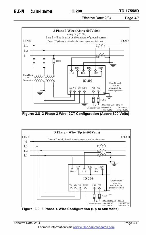
3.3.2 Wiring Diagrams for Various System ConfigurationsRecommended IQ 200 wiring diagrams for current and potential transformers areshown below in figures 3.5 through 3.14. It is the user’s responsibility to determinewhich wiring diagram applies and to specify and install all current transformers,potential transformers, fuses and other components.3.3.2.1 IQ 230 & IQ 230M Current Connector
This warning applies with reference to the current connector.
THE IQ 230 AND IQ 230M TERMINAL BLOCK (FIGURE 2.4d) MUST NEVER BEREMOVED WHILE THE UNIT IS ENERGIZED. PERSONAL INJURY AND / OREQUIPMENT DAMAGE MAY RESULT.
H1A H1B H1C
LINEL3L2L1
PS1 PS2VA VB VC NEU
H2A H2B H2C
IQ 200
LOAD
3 Phase 3 Wire (Up to 600Volts)
Case GroundMust be
connected forproper operation
Control Power
FUSE
IQ 220/IQ 23090-600VAC48-250VDC
IQ 210110-240VAC125-250VDC
Proper CT polarity is critical to the proper operation of the meter
Proper CT polarity is critical to the proper operation of the meter
Figure 3.11 Single Phase 3 Wire Configuration (Up to 600 Volts)
Effective Date: 2/04
TD 17558D
Page 3-9
IQ 200
Effective Date: 2/04 Page 3-9For more information visit: www.cutler-hammer.eaton.com
H1A H1B H1C
LINEN
L1
PS1 PS2VA VB VC NEU
H2A H2B H2C
IQ 200
LOAD
Single Phase 2 Wire (Up to 600Volts)
FUSE
Control PowerIQ 220/IQ 23090-600VAC48-250VDC
IQ 210110-240VAC125-250VDC
Case GroundMust be
connected forproper operation
Proper CT polarity is critical to the proper operation of the meter
Figure 3.12 Single Phase 2 Wire Configuration (Up to 600 Volts)
H1A H1B H1C
LINE
L3L2L1
PS1 PS2VA VB VC NEU
H2A H2B H2C
IQ 210
LOAD3 Phase 4 W ire (Up to 240Volts)
IQ 210 (Line-Powered)
FUSE
N
Control Power
IQ 210 110-240VAC125-250VDC
Case GroundMust be
connected forproper operation
Proper CT polarity is critical to the proper operation of the meter
Figure 3.13 Typical IQ 210 Line-Powered Configuration (Up to 240 Volts)
TD 17558D
Page 3-10 Effective Date: 2/04
IQ 200
Page 3-10 Effective Date: 2/04For more information visit: www.cutler-hammer.eaton.com
H1A H1B H1C
LINE
L3L2L1
PS1 PS2VA VB VC NEU
H2A H2B H2C
IQ 220/IQ 230
LOAD3 Phase 4 Wire (Up to 600Volts)
IQ 220/IQ 230 (Line-Powered)
FUSE
N
Control Power
IQ 220/IQ 23090-600VAC48-250VDC
Case GroundMust be
connected forproper operation
Proper CT polarity is critical to the proper operation of the meter
Figure 3.14 Typical IQ 220/IQ 230 Line-Powered Configuration (Up to 600 Volts)
3.3.3 PowerNet Communications (IQ 220 and IQ 230 Base ModulesOnly)Note: To satisfy proper Wiring Specifications use only Belden 9463 or 3072F, orCulter-Hammer IMPCABLE shielded twisted pair cable or equivalent, according tosystem requirements. SEE TD17513, IMPACC WIRING SPECIFICATIONS BASERULES for more detailed information.Connect the IQ 220 / IQ 230 to the PowerNet network by connecting the twistedpair communication cable to the INCOM™ port located on the rear face of theIQ 220 / IQ 230 Base Module. The polarity of the twisted pair is not important.Tie the communication cable shield to ground only once at the INCOM™ masterdevice. If there is more than one remote INCOM™ compatible devices (such as theIQ 220 or IQ 230) cabled to the master device, tie the communication cable shieldstogether but do not connect to ground.Care must be taken in stripping wire due to close proximity of terminals.
3.3.4 KYZ Pulse Initiator (IQ 220 and IQ 230 Base Modules Only)The KYZ Pulse Initiator output can be wired to a 2-wire (K-Y terminals) or 3 wire(KYZ terminals) pulse receiver. In order to achieve emissions and immunity stan-dards, shield cable should be used. The cable should be grounded on the non-IQBase end. These terminal configurations and the resulting pulse trains are shown in
Effective Date: 2/04
TD 17558D
Page 3-11
IQ 200
Effective Date: 2/04 Page 3-11For more information visit: www.cutler-hammer.eaton.com
figures 3.15 and 3.16. The energy represented by each pulse can be specified bythe user as: apparent (VAh); forward or reverse real (±Wh); or reactive (±varh).The procedure for specifying the energy per pulse is described in section 4.10.9.Each pulse that arrives at the pulse counter indicates that the specified energy hasbeen consumed by the monitored system. The frequency and spacing of thesepulses represent the energy consumption pattern of the monitored system.Because the energy represented corresponds to the energy at the secondarywinding of the CTs and PTs, the CT and PT ratios must be taken into account whenspecifying the energy per pulse value. An example of how to specify the energy perpulse value is given below.Example:
System ConfigurationCT = 1400:5PT = 2:1
Desired value to monitorwatthours
System parametersAssume the IQ 220 is monitoring a constant system power of16,800 Watts.
Step 1: Calculate the CT and PT ratiosCT ratio = 1400/5 = 280PT ratio = 2/1=2
Step 2: Calculate the power at the secondary of the CTs and PTspower at secondaries = 16,800 Watts / (CT ratio x PT ratio)power at secondaries = 16,800 Watts / (280 x 2)power at secondaries = 16,800 Watts / 560power at secondaries = 30 Watts (or 30 watthours in 1
hour)
Step 3: Specify the energy per pulse as desiredSpecify secondary energy per pulse = 1 watthour per pulse;then, each pulse represents system energy of:
(1400/5) x (2/1) x 1; or 560 watthours per pulseor
Specify secondary energy per pulse = 7 watthours per pulse;then, each pulse represents system energy of:
(1400/5) x (2/1) x 7; or 3,920 watthours per pulse
TD 17558D
Page 3-12 Effective Date: 2/04
IQ 200
Page 3-12 Effective Date: 2/04For more information visit: www.cutler-hammer.eaton.com
Y
K
Z
KY
KZ
1 2
∆T
Y
K
Z
KY
KZ
1 42 3
∆T
Figure 3.15 2-Terminal (K-Y)Configuration
Figure 3.16 3-Terminal (K-Y-Z)Configuration
3.3.5 Inputs and Outputs (IQ 230 and IQ 230M only)The IQ 230 offers additional inputs and outputs. In order to achieve the emissionsand immunity standards, shielded cable should be used. The cable should begrounded on the non-IQ Base side of the cable. These inputs and outputs includethe Digital Inputs labeled IN1 and IN2, the Analog Input labeled AN1 and the twoOutputs labeled A1 and A2.Digital inputs and long Modbus responses competefor the same processor band-width. In order to ensure accurate input readings, limit block requests in Modbus to3 variables (6 Modbus registers) when reading digital inputs with pulse width of 200ms between 5 and 10 Hz. Limit block requests in Modbus to 6 variables (12Modbus registers) when reading digital inputs with pulse width of 200 ms between 0and 5 Hz.
Effective Date: 2/04
TD 17558D
Page 3-13
IQ 200
Effective Date: 2/04 Page 3-13For more information visit: www.cutler-hammer.eaton.com
A1-1
A1-2
+ VA2-1
A2-2
+ V
Maximum Input Voltage: 125 Vac / 176 VdcMaximum Current Rating: 96 mAInput/Output Isolation Voltage: 3750 Vrms
A1-1
A1-2
+ VA1-1
A1-2
+ VA2-1
A2-2
+ VA2-1
A2-2
+ V
Maximum Input Voltage: 125 Vac / 176 VdcMaximum Current Rating: 96 mAInput/Output Isolation Voltage: 3750 Vrms
AN1R
AN1I4 – 20 mA
AN1R
AN1I4 – 20 mA
AN1R
AN1I4 – 20 mA
IN1R
IN1I
IN2I
IN2R
IN1R
IN1I
IN2I
IN2R
IN1R
IN1I
IN2I
IN2R
Figure 3.17 Inputs and Outputs
TD 17558D
Page 3-14 Effective Date: 2/04
IQ 200
Page 3-14 Effective Date: 2/04For more information visit: www.cutler-hammer.eaton.com
Effective Date: 2/04
TD 17558DPage 4-1
IQ 200
Effective Date: 2/04 Page 4-1For more information visit: www.cutler-hammer.eaton.com
SECTION 4: OPERATION
4.1 GENERALThe IQ 200 Display Module provides both local display of system values and amethod of assigning an INCOM address to the IQ 220 and IQ 230, and a separateMODBUS address to the IQ 230 to enable communications.The IQ 200 Display Module allows the user to view information and to specify orchange the functions of the IQ 200 system. These items include system and phasedata, min/max data, set points and screen contrast.It also provides a method of assigning a network address and communication baudrate to the IQ 220 and IQ 230 Base variation, should it be networked to a PowerNetmaster device.All functions of the IQ 200 are available through menus visible on the screen of theIQ 200 Display Module Operator Panel. Choice of menu and selection of menuoptions is accomplished by pressing the buttons on the face of the Operator Panel.The menus provide access to the following values and functions:
System DataPhase DataMin/Max DataView Set pointsEdit Set points (with optional password protection / refer to Section 4.6.4 for IQ
230 and IQ 230M seal out feature information)Reset Values (with optional password protection / refer to Section 4.6.4 for IQ
230 and IQ 230M seal out feature information)Contrast AdjustDiagnosticsExit Menu
4.2 BUTTONSThere are four buttons on the Operator Panel: Menu, up and down Scroll, andEnter. Their functions are described in the table below.
Button FunctionMenu Displays the nine different screen menus; displays the
immediately preceding screenScroll Navigates the on-screen selection arrow ( ) through
menu items and through system values to be displayedEnter Confirms the option, value, or screen currently selected
TD 17558D
Page 4-2 Effective Date: 2/04
IQ 200
Page 4-2 Effective Date: 2/04For more information visit: www.cutler-hammer.eaton.com
Display IndicationLg lagging (inductive)Ld leading (capacitive)
4.3 CONTRASTThe contrast of the screen can be adjusted in the Contrast Adjust mode or byholding in the Enter button while pressing the Scroll up arrow button (to decreasecontrast) or the Scroll down arrow button (to increase contrast).
4.4 DISPLAYED SIGN CONVENTIONSThe IQ 200 not only displays system values, but also indicates whether factors arelagging or leading by displaying Lg or Ld, see the table below.
The IQ 200 is shipped with lagging varsand power factor represented by negativevalues at the load, conforming to themathematical sign convention. The IQ 220and IQ 230 allow the user the ability tochange to the power engineer convention,
which assumes positive values at the load. The convention can be changed in theIQ 220 and IQ 230 via the INCOM communications interface. The IQ 220 and IQ230 must be connected to a PowerNet network and programmed accordingly. Onlythe mathematical convention is available when using the IQ 210 Base.The following relationships apply:
The relationships among system power values are shown schematically in fig-ure 4.1.
Effective Date: 2/04
TD 17558DPage 4-3
IQ 200
Effective Date: 2/04 Page 4-3For more information visit: www.cutler-hammer.eaton.com
System DataPhase DataMin/Max DataView SetpointsEdit SetpointsReset ValuesContrast AdjustDiagnosticsExit Menu
Figure 4.2 Main Menu
4.5 USING THE OPERATOR PANELWhen the IQ 200 is first powered on, the Operator Panel screen displays a briefinitialization message identifying the product and version. The screen then displaysthe System Power screen. (At this point, pressing the Scroll arrows will displaysystem data as described in section 4.6 System DataDisplay Mode.)Press the Menu button to proceed. The main menuitems display four at once, as shown in figure 4.2.Every menu item can be displayed by using the Scrollbutton arrows. The item currently selected is indi-cated by the selection arrow to its left.The presence of additional items is indicated by“and/or ” at the right edge of the screen.
Quadrant 2Watts negativeVars positive
Power Factor (-)Lagging
Quadrant 1Watts positiveVars positive
Power Factor (+)Leading
Quadrant 3Watts negativeVars negative
Power Factor (+)Leading
Quadrant 4Watts positiveVars negative
Power Factor (-)Lagging
Quadrant 2Watts negativeVars negative
Power Factor (+)Lagging
Quadrant 1Watts positiveVars negative
Power Factor (-)Leading
Quadrant 3Watts negativeVars positive
Power Factor (-)Leading
Quadrant 4Watts positiveVars positive
Power Factor (+)Lagging
Reactive Power
Real Power
Mathematical Convention
Reactive Power
Real Power
Power Engineer Convention
Figure 4.1 System Power Value Relationships
TD 17558D
Page 4-4 Effective Date: 2/04
IQ 200
Page 4-4 Effective Date: 2/04For more information visit: www.cutler-hammer.eaton.com
Figure 4.3 System Display 3 and 4 Wire Systems
IQ 230 &IQ 230MONLY
Keep in mind that the values displayed under several menu items depend on whichunit you are using and whether the system being monitored is 3 or 4 wire, andrequire that the appropriate configuration be selected under the Edit Setpointsmenu. Menu descriptions cover both 3 and 4 wire systems where appropriate.Note: The lagging or leading indicator and any signs may be the opposite of thatshown in the sample screens.
4.6 SYSTEM DATA DISPLAY MODEThe System Data menu provides access to System information monitored by the IQ200.Press Menu to display the list of available items.Position the selection arrow next to the System Data menu item and press Enter.The screens shown in figure 4.3 display as the Scroll down arrow is pressed.
4.6.1 3 Wire System and 4 Wire SystemThe System Data screens, shown below, are the same for 3 and 4 wire systems.Only when you are using the IQ 230 or IQ 230M will you see the digital inputcounters and lock status display screens.
Effective Date: 2/04
TD 17558DPage 4-5
IQ 200
Effective Date: 2/04 Page 4-5For more information visit: www.cutler-hammer.eaton.com
4.6.2 System Input (IQ 230 and IQ 230M only)The System Input displays the accumulated counts of the two digital inputs and thevalue of the 4 to 20ma analog input. The digital inputs count the positive andnegative edges of a square wave signal. The signal must have an amplitude greaterthan 12 volts and will be clamped at 50 volts. The counts will rollover the display at65535. The counts can be tracked to 4294967295 via INCOM and the MODBUSpass through commands before roll over occurs.The 4 to 20ma analog input will be represented as 0 to 100 percent on the display.
4.6.3 System Lock (IQ 230 and IQ 230M only)The lockout feature is unique to the IQ 230 type models. The feature is a physicalshaft or button protruding from the top of the base. The shaft has a hole in it so thewire tamper proof seal can be employed to disable it. The feature is a toggle. Pressthe button and the unit will be locked. Press the button again and the unit will beunlocked.While in the locked state changes to setup and reset values (listed below) will bedenied. When a user tries to change any of the values in the list below an ERRORTRY AGAIN message will appear. Simple unlock the IQ 230 to access thesefunctions.• System Frequency• Wiring Configuration• CT Ratio• PT Ratio• Demand Window• KYZ Setup• Reset Peak Demand• Reset System Energy
4.7 PHASE DATA DISPLAY MODEThe Phase Data menu provides access to all Phase information monitored by the IQ200.Press Menu to display the list of available items.Position the selection arrow next to the Phase Data menu item and press Enter.
4.7.1 3 Wire SystemThe four screens shown in figure 4.4 display as the Scroll down arrow is pressed.
TD 17558D
Page 4-6 Effective Date: 2/04
IQ 200
Page 4-6 Effective Date: 2/04For more information visit: www.cutler-hammer.eaton.com
Figure 4.4 Phase Display 3 Wire Systems
Figure 4.5 Phase Display 4 Wire Systems
Effective Date: 2/04
TD 17558DPage 4-7
IQ 200
Effective Date: 2/04 Page 4-7For more information visit: www.cutler-hammer.eaton.com
4.7.2 4 Wire SystemThe 10 screens shown in figure 4.5 display as the Scroll down arrow is pressed.
4.8 MIN/MAX DATA DISPLAY MODE
4.8.1 3 Wire SystemThese screens, shown in figure 4.6, display the minimums and maximums of valuesmonitored by the IQ 200.Press Menu to display the list of available items.Position the selection arrow next to Min/Max Data and press Enter.The ten screens shown below display as the Scroll down arrow is pressed.
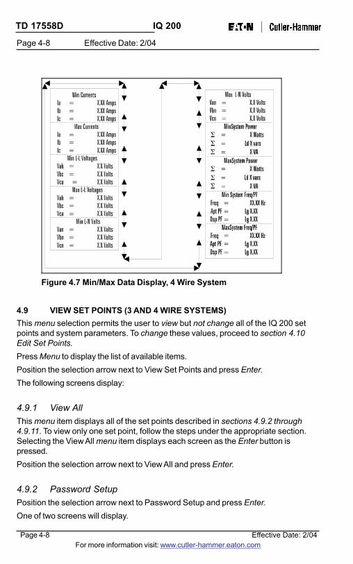
4.8.2 4 Wire SystemThese screens, shown in figure 4.7, display the minimums and maximums of valuesmonitored by the IQ 200.Press Menu to display the list of available items.Position the selection arrow next to Min/Max Data and press Enter.The 10 screens shown below display as the Scroll down arrow is pressed.
Figure 4.6 Min/Max Data Display, 3 Wire System
TD 17558D
Page 4-8 Effective Date: 2/04
IQ 200
Page 4-8 Effective Date: 2/04For more information visit: www.cutler-hammer.eaton.com
4.9 VIEW SET POINTS (3 AND 4 WIRE SYSTEMS)This menu selection permits the user to view but not change all of the IQ 200 setpoints and system parameters. To change these values, proceed to section 4.10Edit Set Points.Press Menu to display the list of available items.Position the selection arrow next to View Set Points and press Enter.The following screens display:
4.9.1 View AllThis menu item displays all of the set points described in sections 4.9.2 through4.9.11. To view only one set point, follow the steps under the appropriate section.Selecting the View All menu item displays each screen as the Enter button ispressed.Position the selection arrow next to View All and press Enter.
4.9.2 Password SetupPosition the selection arrow next to Password Setup and press Enter.One of two screens will display.
Figure 4.7 Min/Max Data Display, 4 Wire System
Effective Date: 2/04
TD 17558DPage 4-9
IQ 200
Effective Date: 2/04 Page 4-9For more information visit: www.cutler-hammer.eaton.com
Figure 4.8 No Password Required
n
Password Setup
Use Password:
Figure 4.8 No PasswordRequired
Figure 4.9 Password Required
y
Password Setup
Use Password:
Baud Rate = XXXXAddress = XXX Hex
INCOM Setup
Figure 4.10 INCOM Setup
Baud Rate = XXXXAddress = XXX Hex
MODBUS Setup
Figure 4.11 MODBUS Setup
One screen, figure 4.8, indicates that nopassword is necessary to change the IQ200 set points or system parameters.
The other screen, figure 4.9, indicatesthat a password is required to changeset points or system parameters.
4.9.3 INCOM™ Setup (IQ 220 and IQ 230 Base Modules only)Position the selection arrow next toINCOM™ Setup and press Enter.This screen, shown in figure 4.10,indicates the baud rate at which theIQ 220/IQ 230 will communicate overthe PowerNet network, and indicatesthe network address (in hexadecimal)assigned to the IQ 220/IQ 230. Thebaud rate and the address must be setto the values required by the PowerNetnetwork for network communication to occur.
4.9.4 MODBUS™ Setup (IQ230M Base Modules only)Position the selection arrow next toMODBUS™ Setup and press Enter.This screen, shown in figure 4.11,indicates the baud rate at which theIQ 230M will communicate over theMODBUS network, and indicates thenetwork address (in hexadecimal)assigned to the IQ 230M. The baud rate and the address must be set to the valuesrequired by the MODBUS network for network communication to occur. TheModbus address should be limited by the user to 0FF (hexadecimal).
TD 17558D
Page 4-10 Effective Date: 2/04
IQ 200
Page 4-10 Effective Date: 2/04For more information visit: www.cutler-hammer.eaton.com
4.9.5 System FrequencyPosition the selection arrow next to SystemFrequency and press Enter.This screen, shown in figure 4.12, indicatesthe frequency selected for the system beingmonitored. The screen will display either
50 Hz or 60 Hz. If the frequency displayed is not correct, proceed to section 4.10Edit Set Points.
4.9.6 Wiring ConfigurationPosition the selection arrow next to WiringConfiguration and press Enter.This screen, shown in figure 4.13, indicatesthe wiring configuration selected as theconfiguration of the system being monitored.The screen will display either 3 Wire or4 Wire. If the wiring configuration displayed isnot correct, proceed to section 4.10 Edit SetPoints.
4.9.7 CT RatioPosition the selection arrow next to CTRatio and press Enter.This screen, shown in figure 4.14, indicatesthe current transformer ratio selected as theratio of the current transformers being usedwith the IQ 200. If the ratio displayed is notcorrect, proceed to section 4.10 Edit SetPoints.
4.9.8 PT RatioPosition the selection arrow next to PT Ratioand press Enter.This screen, shown in figure 4.15, indicatesthe potential transformer ratio selected as theratio of the potential transformers being usedwith the IQ 200. If the ratio displayed is notcorrect, proceed to section 4.10 Edit SetPoints.
System Frequency60 Hz
Figure 4.12 System Frequency
Wiring Configuration4 Wire
Figure 4.13 Wiring Configuration
CT Ratio5 : 5
Figure 4.14 CT Ratio
PT Ratio1.0 : 1
Figure 4.15 PT Ratio
Effective Date: 2/04
TD 17558DPage 4-11
IQ 200
Effective Date: 2/04 Page 4-11For more information visit: www.cutler-hammer.eaton.com
4.9.9 Demand WindowPosition the selection arrow next to Demand Window and press Enter.
This screen, shown in figure 4.16, indicatesthe time window over which demand param-eters are measured. If the time displayed isnot correct, proceed to section 4.10 Edit SetPoints.
4.9.10 KYZ Setup (IQ 220 and IQ 230 Base Module only)Position the selection arrow next to KYZ Setup andpress Enter.This screen, shown in figure 4.17, indicates thesystem value which the IQ 220 and the IQ 230 willmonitor, or Track. It also indicates the energy perpulse Rate over which energy demand (consump-tion) is measured. If the values displayed are notcorrect, proceed to section 4.10 Edit Set Points.
4.9.11 Digital Output Setup (IQ 230 & IQ 230M Base Module Only)Position the selection arrow next to Output A Setup and press Enter.
This screen, shown in figure 4.18, indicatesthe status of the two “form A” output relays.Each of the two relays can be programmed torespond to MESSAGE, VOLTAGE orPHASE. When Null is displayed the output isdisabled.When in MESSAGE mode the relay will beopen or closed depending on an externalmessage received by the unit.In PHASE mode the output will be in closed
state when the three phase voltages are in phase and the open state when the threephase voltages are out of phase.When in Voltage mode the output will be closed when the voltage strays from the100% nominal reading. The nominal readings will be 120, 240, 480 and 575. Theprogrammable trip value will determine when the output will be closed. If the rmsvoltage drops below a percentage less than 100% the relay will be closed. If the rmsvoltage goes above a percentage that is above 100% the relay will be closed. Inboth cases the relay will stay closed until open by a message. For example if thenominal voltage is 480 V and you want the unit to trip if the voltage drops below 420V, multiply 420 by 100 and divide it by 480 to find your setting.
Watt Demand Window
5 Min
Figure 4.16 Demand Window
Track :Rate :
KYZ Output SetupNone
1
Figure 4.17 KYZ Setup
Output A1 = NullOutput A2 = NullTrip Value = 0%
Output A Setup
Figure 4.18 Output A Setup
TD 17558D
Page 4-12 Effective Date: 2/04
IQ 200
Page 4-12 Effective Date: 2/04For more information visit: www.cutler-hammer.eaton.com
This screen also shows the status of the trip value. (Note: the MODBUS andINCOM forms of communication do not read the output values). Refer to 4.10.8notes for information on entering proper nominal readings.
4.9.12 ExitPressing Enter when this menu item is selected returns the display to the mainmenu.
4.10 EDIT SET POINTS (3 AND 4 WIRE SYSTEMS)This menu selection permits the user to change all of the IQ 200 set points andsystem parameters.Press Menu to display the list of available items.Position the selection arrow next to Edit SetPoints and press Enter.If the Password option has beenenabled, the system requests thepassword via the screen shown in figure4.19.To enter the password, press Enter tomove the underline to the desired digit.Then use the Scroll up arrow to increasethe digit or the Scroll down arrow todecrease the digit. When the desiredchoice is displayed, press Enter to lock inthe selection.If an incorrect password is entered, the message Password Incorrect displays.Press Menu to return to the previous screen showing Edit Set Points selected.Press Enter to retry entering the password.If the correct password is entered, or if the Password option is not enabled, thefollowing screens display:
4.10.1 Edit AllThis menu item displays all of the set points described in sections 4.10.2 through4.10.11. To edit only one set point, follow the steps under the appropriate section.Selecting the Edit All menu item displays the screens shown below as the Scrolldown arrow is pressed. (Note: the lagging or leading indicator and any signs may bethe opposite of that shown in the sample screens.)Position the selection arrow next to Edit All and press Enter.The following screens display:
Figure 4.19 Password Entry
Enter Password00000
Effective Date: 2/04
TD 17558DPage 4-13
IQ 200
Effective Date: 2/04 Page 4-13For more information visit: www.cutler-hammer.eaton.com
Use Password = n New Password = XXXXX
Password Setup
Figure 4.20 Password Setup
4.10.2 Password SetupPosition the selection arrow next to Password Setup and press Enter. The screenchanges to show New Password selected and the first digit of the current passwordunderlined. To change any digit of the password, first select it by pressing Enter tomove the underline to the desired digit. Then use the Scroll up arrow to increase thedigit or the Scroll down arrow to decrease the digit. When the desired choice isdisplayed, press Enter to lock in the selection.
This screen, shown in figure 4.20,allows the user to specify if a passwordis required to change the IQ 200 setpoints or system parameters. It alsoshows the user what the password isor would be if it were in use.The screen initializes with Use Pass-word selected and the current choice
displayed. To specify if a password is required, press either of the Scroll arrows totoggle between y and n. When the desired choice is displayed, press Enter to lockin the selection.The screen changes to show New Password selected and the first digit of thecurrent password underlined. To change any digit of the password, first select it bypressing Enter to move the underline to he desired digit. Then use the Scroll uparrow to increase the digit or the Scroll down arrow to decrease the digit. When thedesired choice is displayed, press Enter to lock in the selection.If the procedure completes successfully, Download Accepted appears briefly. Thedisplay then returns to the previous screen.If an error occurs in the New Password selection process, an error messagedisplays. Press Enter to return to the previous screen, and repeat the steps above.
4.10.3 INCOM™ Setup (IQ 220 and IQ 230 Base Modules only)Note: A display is required to configure the INCOM™ address.To set these values on IQ 220 and IQ 230 Base modules installed without apermanently connected IQ 200 display module, temporarily connect an IQ 200display module and follow the procedure below.Position the selection arrow next toINCOM™ Setup and press Enter.This screen, shown in figure 4.21, displaysthe baud rate at which the IQ 220 and IQ230 will communicate over the PowerNetnetwork, and indicates the network address(in hexadecimal) currently assigned to theIQ 220 or IQ 230.The screen initializes with Baud Rate
Baud Rate = XXXXAddress = XXX Hex
INCOM SETUP
Figure 4.21 INCOMTM Setup
TD 17558D
Page 4-14 Effective Date: 2/04
IQ 200
Page 4-14 Effective Date: 2/04For more information visit: www.cutler-hammer.eaton.com
selected and the current value displayed. To select a baud rate at which the IQ 220or IQ 230 will communicate over the PowerNet network, press either of the Scrollarrows to step through the choices 9600 or 1200 baud. When the desired choice isdisplayed, press Enter to lock in the selection.The screen changes to show Address selected and the first digit of the currentnetwork address (in hexadecimal) assigned to the IQ 220 or IQ 230 underlined. Tochange any digit of the address, first select it by pressing Enter to move the under-line to the desired digit. Then use the Scroll up arrow to increase the digit or theScroll down arrow to decrease the digit. When the desired choice is displayed,press Enter to lock in the selection.If the procedure completes successfully, Download Accepted appears briefly. Thedisplay then returns to the previous screen.
4.10.4 MODBUS™ Setup (IQ 230M Base Module only)Note: A display is required to configure the MODBUS™ address.To set these values on IQ 230 Base modules installed without a permanentlyconnected IQ 200 display module, temporarily connect an IQ 200 display moduleand follow the procedure below.Position the selection arrow next toMODBUS™ Setup and press Enter.This screen, shown in figure 4.22, displaysthe baud rate at which the IQ 230 willcommunicate over the MODBUS network,and indicates the network address (inhexadecimal) currently assigned to theIQ 230.The screen initializes with Baud Rateselected and the current value displayed. To select a baud rate at which the IQ 230will communicate over the PowerNet network, press either of the Scroll arrows tostep through the choices of 19200 or 9600 baud. When the desired choice isdisplayed, press Enter to lock in the selection.The screen changes to show Address selected and the first digit of the currentnetwork address (in hexadecimal) assigned to the IQ 230 underlined. To changeany digit of the address, first select it by pressing Enter to move the underline to thedesired digit. Then use the Scroll up arrow to increase the digit or the Scroll downarrow to decrease the digit. When the desired choice is displayed, press Enter tolock in the selection.If the procedure completes successfully, Download Accepted appears briefly. Thedisplay then returns to the previous screen.
4.10.5 System FrequencyPosition the selection arrow next to System Frequency and press Enter.
Baud Rate = XXXXAddress = XXX Hex
MODBUS Setup
Figure 4.22 MODBUS Setup
Effective Date: 2/04
TD 17558DPage 4-15
IQ 200
Effective Date: 2/04 Page 4-15For more information visit: www.cutler-hammer.eaton.com
This screen, shown in figure 4.23, displaysthe electrical system frequency in Hz.This screen initializes with the frequency ofthe system being monitored selected anddisplayed. The screen will display either 60Hz or 50 Hz.To specify the frequency of the system beingmonitored, press either of the Scroll arrowsto toggle between 60 Hz and 50 Hz. Whenthe desired choice is displayed, press Enter to lock in the selection.If the procedure completes successfully, Download Accepted appears briefly. Thedisplay then returns to the previous screen.
4.10.6 Wiring ConfigurationPosition the selection arrow next to Wiring Configuration and press Enter.This screen displays the current wiring configuration of the system being monitored.This screen, shown in figure 4.24,initializes with the wiring configuration ofthe system being monitored selected anddisplayed. The screen will display either 3Wire or 4 Wire.To specify the wiring configuration of thesystem being monitored, press either ofthe Scroll arrows to toggle between 3 Wireand 4 Wire. When the desired choice isdisplayed, press Enter to lock in theselection.
4.10.7 CT RatioNote: See table 2.4 for data ranges before specifying the CT ratio.Position the selection arrow next to CT Ratio and press Enter.This screen, shown in figure 4.25, displays the ratios of the current transformersconnected to the IQ 200. This screeninitializes with the ratio of the currenttransformers being used with the IQ 200selected and displayed.To specify the ratio of the current transform-ers being used with the IQ 200, press eitherof the Scroll arrows repeatedly to stepthrough the choices individually, or pressand hold either of the Scroll arrows to stepthrough the choices rapidly. There are 256 choices from 5 to 8000, displayed asfollows:
Wiring Configuration4 Wire
Figure 4.24 Wiring Configuration
CT Ratio5 : 5
Figure 4.25 CT Ratio
System Frequency60 Hz
Figure 4.23 System Frequency
TD 17558D
Page 4-16 Effective Date: 2/04
IQ 200
Page 4-16 Effective Date: 2/04For more information visit: www.cutler-hammer.eaton.com
• 5 to 110 in increments of 5• 110 to 1000 in increments of 10• 1000 to 1250 in increments of 25• 1250 to 8000 in increments of 50
When the desired choice is displayed, press Enter to lock in the selection.If the procedure completes successfully, Download Accepted appears briefly. Thedisplay then returns to the previous screen.
4.10.8 PT RatioNote: See table 2.4 for data ranges before specifying the PT ratio.Position the selection arrow next to PT Ratio and press Enter.
This screen, shown in figure 4.26, displaysthe ratio of the potential transformersconnected to the IQ 200.This screen initializes with the ratio of thepotential transformers being used with the IQ200 selected and displayed.To specify the potential transformer ratio ofthe potential transformers being used withthe IQ 200, press either of the Scroll arrows
repeatedly to step through the choices individually, or press and hold either of theScroll arrows to step through the choices rapidly. There are 256 choices from 1.0 to1690, displayed as follows:
• 1.0 to 6 in increments of 0.1• 6 to 20 in increments of 1• 20 to 260 in increments of 5• 260 to 1690 in increments of 10
Note: If no potential transformers are being used set the PT ratio at 1.0 to 1.Note: Enter the PT Ratio two times every time you install the IQ 230. This willensure proper default voltage and calculation when your using the Voltage Tripfeature.If the procedure completes successfully, Download Accepted appears briefly. Thedisplay then returns to the previous screen.
4.10.9 Demand WindowPosition the selection arrow next to Demand Window and press Enter.This screen, shown in figure 4.27, displays the current value of the demand time
PT Ratio1.0 : 1
Figure 4.26 PT Ratio
Effective Date: 2/04
TD 17558DPage 4-17
IQ 200
Effective Date: 2/04 Page 4-17For more information visit: www.cutler-hammer.eaton.com
window.The screen initializes with the time windowover which demand (parameters) aremeasured, selected and displayed.To specify Demand Window, press either ofthe Scroll arrows to step through thechoices. There are 8 choices from 5 minutesto 60 minutes, displayed as follows:
• 5 min. to 30 min. in increments of 5 min.• 45 min.• 60 min.When the desired choice is displayed, press Enter to lock in the selection.If the procedure completes successfully, Download Accepted appears briefly. Thedisplay then returns to the previous screen.The Demand Window is a fixed period of time over which average system param-eters are calculated. For example, setting the Demand Window to 15 instructs theIQ 200 to calculate the average current or power over the past 15 minutes and toupdate that calculation every 15 minutes.If multiple IQ 220 or IQ 230 units exist on a PowerNet network, all their DemandWindows can be simultaneously reset and synchronized using INCOM™ communi-cation unless the lockout feature is applied on the IQ 230.
4.10.10 KYZ Setup (IQ 220 and IQ 230 Base Modules Only)Position the selection arrow next to KYZ Setup and press Enter.
This screen, shown in figure 4.28, displays thesystem value communicated by the KYZ pulse train.This screen initializes with the system value that theIQ 220 or IQ 230 will Track.To select a system value (+kWh, +kvarh, kVAh)which the IQ 220 or IQ 230 will Track, press either ofthe Scroll arrows repeatedly to setup through thechoices individually, or press and hold either of the
Scroll arrows to step through the choices rapidly. There are up to 32 choices from1/32 to 100 displayed as follows:Note: Some rates are available only in the IQ 220 or IQ 230 firmware version 1.02and greater.
Demand Window
5 Min
Figure 4.27 Demand Window
Version 1.01 and Earlier: Version 1.02 and Later:1 through 10 in increments of 1 1/32, 1/16, 1/8, ¼, 3/8, ½, 5/8, ¾20, 40, 50, 60, 80, 100 1 through 15 in increments of 1
20 through 100 in increments of10
Track :Rate :
KYZ Output SetupNone
1
Figure 4.28 KYZ Setup
TD 17558D
Page 4-18 Effective Date: 2/04
IQ 200
Page 4-18 Effective Date: 2/04For more information visit: www.cutler-hammer.eaton.com
When the desired choice is displayed, press Enter to lock in the selection.If the procedure completes successfully, Download Accepted appears briefly. Thedisplay then returns to the previous screen.The screen changes to show the energy per pulse Rate selected. To change therate, press either of the Scroll arrows to step through the choices. When the desiredchoice is displayed, press Enter to lock in the selection. See 3.3.4 KYZ PulseInitiator for details about choosing Track and Rate.If the procedure completes successfully, Download Accepted appears briefly. Thedisplay then returns to the previous screen.
4.10.11 Digital Output Setup (IQ 230 & IQ 230M Base Module Only)Position the selection arrow next to Output A Setup and press Enter.The screen, shown in Fig 4.29, indicates the selection of the mode to be used forthe two outputs and the percentage used relative to the trip value assigned to the IQ
230. The screen initializes with Mode selectedand the current value displayed.To select a mode to be assigned to output A1 orA2, press either of the Scroll arrows to stepthrough the choices MESSAGE, VOLTAGE,PHASE or NULL. When the desired choice isdisplayed, press Enter to lock in the selection.The screen changes to show the selection forA2. Repeat the method used for A1. The screenchanges to show the selection for Trip Value.Then use the up Scroll arrow to increase the
value or the down Scroll arrow to decrease the value. The range is from 0 to 124percent. When the desired choice is displayed, press Enter to lock in the selection.In Message mode, the outputs are opened or closed via a message through thecommunications port. In Phase mode, the outputs are opened or closed dependingon proper phasing. In Voltage mode, when the PT Ratio is entered twice thepowered A, B & C phases are sampled and a default value is selected from one offour: 120, 240, 480 or 575. From this point the Trip Value is determined by thedefault value chosen. This is all computed internally based on 3 Phase Voltagereadings. This value can not be viewed and will only be one of the four values listed.Enter the PT Ratio two times every time you install the IQ 230. This will ensureproper default voltage and calculation when your using the Voltage Trip feature.If the procedure completes successfully, Download Accepted appears briefly. Thedisplay then returns to the previous screen.
4.10.12 Message to Outputs A1 and A2 (IQ 230 & IQ 230M Base ModuleOnly) Pressing Enter when this menu item is selected returns the display to the MainPosition the selection arrow next to Message to A1 | A2 and press Enter. The
Output A1 = NullOutput A2 = NullTrip Value = 0%
Output A Setup
Figure 4.29 Output A Setup
Effective Date: 2/04
TD 17558DPage 4-19
IQ 200
Effective Date: 2/04 Page 4-19For more information visit: www.cutler-hammer.eaton.com
No
Rst Amps Min/Max
Are you sure?
Figure 4.32 Reset Amps Min/Max
screen, shown in Fig 4.30, indicates the selection of the message to be sent toeither of the two outputs. The initial result should be NULL. This means if you exitno message will be sent.To select the message to be assigned tooutput A1 or A2, press either of the Scrollarrows to step through the choices SET,CLEAR or NULL. When the desired choice isdisplayed, press Enter to lock in the selec-tion. The possible selections will be deter-mined by the choices made in Output ASetup. A PHASE choice will not let you send amessage to that output. A VOLTAGE choice will let you chose NULL or CLEAR. AMESSAGE choice will let you chose all possibilities. When the desired choice isdisplayed, press Enter to lock in the selection.When Download Accepted appears briefly the messages to the outputs will be sent.The display then returns to the previous screen.
4.10.13 ExitPressing Enter when this menu item is selected returns the display to the MainMenu.
4.11 RESET VALUESThis menu item allows the user to reset to zero or to default IQ 200 system valuesand parameters.Press Menu to display the list of available items.Position the selection arrow next to Reset Values and press Enter.The screen, in figure 4.31 on the next page, displays the Reset Values choices.Every choice can be displayed by using the Scroll arrows. The item currentlyselected is indicated by an arrow to its left. If Rst All Min/Max is chosen, all the Min/Max values (Amps, Volts, Power, Freq, PF) will be reset.To select a choice, position the selection arrow next to it and press Enter.For all choices selected, a screen similar tofigure 4.32 displays. For other choices,Reset Amps Min/Max is replaced by thedescription of the choice.Pressing Enter while No is selected returnsyou to the Reset Values screen.To change the selection to Yes, presseither of the Scroll arrows to togglebetween Yes and No. When Yes isdisplayed as selected, press Enter to lockin the selection. If the procedure completes successfully, Download Acceptedappears briefly. The display then returns to the previous screen.
Output A1 = NullOutput A2 = Null
A Output Message
Figure 4.30 Message to A1 | A2
TD 17558D
Page 4-20 Effective Date: 2/04
IQ 200
Page 4-20 Effective Date: 2/04For more information visit: www.cutler-hammer.eaton.com
Exit
Rst Comm StatsRst Digital Inputs
Rst Peak DemandsRst System EnergyRst All Min/MaxRst Amps Min/MaxRst Volts Min/MaxRst Power Min/MaxRst FreqPF Min/Max
IQ 230 & IQ 230 M only
IQ 230 &IQ 230 M only
Figure 4.31 Reset Values
"Up" to decrease"Down" to increase"Menu" to exit
Contrast Adjust
Figure 4.33 Contrast Adjust
4.12 CONTRAST ADJUSTThis screen, shown in figure 4.33, allows the user to adjust the appearance of thedisplay for best viewing.Press Menu to display the list of available items.Position the selection arrow next to Contrast Adjust and press Enter.Press either of the Scroll arrows repeatedly to see the contrast change slowly, orpress and hold either of the Scroll arrows to see the contrast change rapidly. Pressthe Menu button to exit and return to the main menu.
Alternatively, the contrast of the screen canbe adjusted without entering the ContrastAdjust menu by holding in the Enter buttonwhile pressing the Scroll up arrow (todecrease contrast) or the Scroll downarrow (to increase contrast).
4.13 DIAGNOSTICSThis menu item is reserved for the use ofCutler-Hammer service personnel. There
are no user-accessible functions on this screen.
4.14 EXIT MENUPress Enter to return to the previous menu; press Enter or Menu to return to theSystem Data menu. (See figure 4.3 in Section 4.6)
Effective Date: 2/04
TD 17558DPage 5-1
IQ 200
Effective Date: 2/04 Page 5-1For more information visit: www.cutler-hammer.eaton.com
SECTION 5: NETWORK COMMUNICATION PROTOCOLS
5.1 MODBUS RS485 NETWORKThe IQ 230M can be accessed by MODBUS messages through a RS485 interface.In order to do this properly please refer to IL 17384, Part A and Part B: IMPACCCommunications Standard, EATON | Cutler-Hammer “Modicon MODBUS Protocol”and IL 66A7508H01 Instructions for the mMINT MODBUS Translator Module.The following simplified rules apply to a given system consisting of master and slavedevices. For more complex configurations please refer to standard MODBUS RTUwiring specification rules for the RS485 network.The recommended MODBUS cable has twisted-pair wires (24AWG stranded 7x32conductors with PVC insulation) having an aluminum/mylar foil shield with drainwire.The maximum system capacity is 4,000 feet of communications cable and 32devices on the MODBUS RTU network.Make sure the twisted-pair wire is recommended for MODBUS RTU network use.Use shielded twisted-pair wire to connect each slave to the MODBUS RTU network,daisy-chain style. The polarity of the twisted pair is critically important, MODPIN1 isMOD(A) and MODPIN2 is MOD(B).Tie the communication cable shield to ground only once at the MODBUS masterdevice. If there are more than one remote MODBUS compatible device cabled tothe master device, tie the communication cable shields together but do not connectto ground.
5.2 OVERVIEWThe contents of MODBUS registers are product objects (e.g. Ia – phase A current).There is a single register map for all Eaton | Cutler-Hammer IQ products. Conse-quently, the objects listed in the following tables are identical registers called out bythe mMINT. The IQ 230M supports the fixed values only and occupy two registers.See table 5.1.
TD 17558D
Page 5-2 Effective Date: 2/04
IQ 200
Page 5-2 Effective Date: 2/04For more information visit: www.cutler-hammer.eaton.com
Table 5.1 IQ 200 ObjectsObjects - (complete list) Units Modbus
Address (hex)INCOM Products -
(partial list)
Name Numeric Fixed point(FP)
(hex)
FPscalefactor
IQ-200
primary 1200 or 1800 hi xsecondary 1200 or 1800 lo xstatus
cause cause 1201 or 1801 xIA A 1802 10 xIB A 1804 10 xIC A 1806 10 xIG A 1808 10IN A 180A 10
current
IAvg A avg 180C 10VAB V 180E 10 xVBC V 1810 10 xVCA V 1812 10 xL-L voltage
VLLavg Vavg 1814 10VAN V 1816 10 xVBN V 1818 10 xVCN V 181A 10 x
L-N voltage
VLN V avg 181C 10N-G voltage VNG V 181E 10
peak IA demand A 1820 10 xpeak IB demand A 1822 10 xpeak IC demand A 1824 10 xpeak IG demand A 1826 10
current
peak IN demand A 1828 10real 3 ph (power) W 182A 1 x
reactive 3 ph VAR 182C 1 xpowerapparent 3 ph VA 182E 1 x
frequency freq Hz 1834 10 xK-factor K-factor 1836 1
THD factor THD factor 1838 1
Effective Date: 2/04
TD 17558DPage 5-3
IQ 200
Effective Date: 2/04 Page 5-3For more information visit: www.cutler-hammer.eaton.com
5.3 FUNCTION CODESThe IQ 200 responds to a limited number of MODBUS function codes. These arefunction codes 04 and 10 hex.
5.4 BLOCK OF REGISTERSUsing the 04 MODBUS command you can read any block from table 5.1. Thebeginning address and the size of the block are the elements of the 04 command.Below is an example of message for retrieval of data.
Table 5.1 IQ 200 Objects Cont.Objects - (complete list) Units Modbus
Address (hex) INCOM Products -
(partial list)
Name
Numeric
Fixed point (FP)
(hex)
FP scale factor
IQ-200
power A ph W 183A 1 x B ph W 183C 1 x C ph W 183E 1 x reactive A ph VAR 1840 1 x reactive B ph VAR 1842 1 x reactive C ph VAR 1844 1 x apparent A ph VA 1846 1 x apparent B ph VA 1848 1 x apparent C ph VA 184A 1 x
power factor displacement A ph pf 184C 100 x displacement B ph pf 184E 100 x displacement C ph pf 1850 100 x apparent A ph pf 1852 100 x apparent B ph pf 1854 100 x apparent C ph pf 1856 100 x
power peak demand W 1858 1 x source 1 VAB V 185A 10
VBC V 185C 10 VCA V 185E 10 freq Hz 1860 10
source 2 VAB V 1862 10 VBC V 1864 10 VCA V 1866 10 freq Hz 1868 10
power power (real 3 ph) W 186A 1 x power factor pf (*) pf 186C 100 x
prod ID prod ID 186E x frequency freq Hz 1870 100 x
energy forward kWh 1872 1 x reverse kWh 1874 1 x net kWh 1876 1 x
reactive energy lead kVARh 1878 1 x lag kVARh 187A 1 x net kVARh 187C 1 x
energy (4 reg) apparent kVAh 187E 1 x
TD 17558D
Page 5-4 Effective Date: 2/04
IQ 200
Page 5-4 Effective Date: 2/04For more information visit: www.cutler-hammer.eaton.com
The register data in the response message are packed as two bytes per register.For each register, the first byte contains the high-order bits and the second containsthe low-order bits.Because all of the data in the IQ 230M is stored as a 32 bit value, you always wantto retrieve two registers to get the result. See below for an example.One item is made up of 4 bytes of information. Using table 5.1 locate the MODBUSaddress of 1804, this is the numeric object or item for IB. Each item (in this exampleIB) equals 2 registers. Each register equals 2 bytes, therefore 1 item (IB) equals 4bytes.
There are two locations that are not 32 bit signed integers, “status cause” and“product ID”. These two locations will give valid single register (two byte) responseand respond in the following format.
Field Name Example (HEX)
Slave Address TBD Function 04 Starting Address Hi 18 Starting Address Lo 03 Number of Points Hi 00 Number of Points Lo 02 Error Check (LRC or CRC) --
Table 5.2 Example Messages
Table 5.3 Example Responses
Field Name Example (Hex)
Slave Address TBD Function 04 Byte Count 04 Data Hi (Bits 15 thru 8) 01 Data Lo (Bits 7 thru 0) 02 Data Hi (Bits 31 thru 24) 00 Data Lo (Bits 23 thru 16) 0A Error Check (LRC or CRC) --
Effective Date: 2/04
TD 17558DPage 5-5
IQ 200
Effective Date: 2/04 Page 5-5For more information visit: www.cutler-hammer.eaton.com
Field Name Example (Hex)
Slave Address TBD Function 04 Byte Count 04 Data Hi (Register X (1800)) 01 Data Lo (Register X (1800)) 02 Data Hi (Register X+1 (1801)) 00 Data Lo (Register X+1 (1801)) 0A Error Check (LRC or CRC) --
Table 5.3A Example Responses
5.5 UNDERSTANDING ADDRESS 1800 AND 1801Address 1800 and 1801 are made up of three fields, Primary, Secondary andCause. The Primary field is the high byte of address 1800. The Secondary field isthe low byte of 1800. The Cause field is all of address 1801. Values found in thesethree fields are defined below.
Definition Cause Field Energy Error 2 Decimal RAM Error 39 Decimal ROM Error 43 Decimal Calibration Error 113 Decimal External RAM Error 44 Decimal Setpoint Error 77 Decimal No Error 1 Decimal
Page 5-6 Effective Date: 2/04For more information visit: www.cutler-hammer.eaton.com
5.6 EXTENDED COMMUNICATIONS VIA MODBUSSince a control error could result in unwanted actions initiated by MODBUS the IQ200 requires a specific protocol by the MODBUS Master in order to perform controlrelated functions within the IQ 200A set of registers is reserved for the control protocol. They begin at register 6200hex and extend through 6203 hex. These three registers are written with a ‘slaveaction number’ and it’s 1’s complement, using function code 10 hex. The format ofthe data is shown in figure 5.2. These three registers, and only these three registers,must be written in one MODBUS transaction.If the ‘slave action number’ is valid and not blocked by a LOCKED system , the IQ200 issues the ‘slave action’ control command.
1's Complement of Slave Action Byte1
15 14 13 12 11 10 9 8 7 6 5 4 3 2 1 0
Register 425091 (620216)
15 14 13 12 11 10 9 8 7 6 5 4 3 2 1 0
Register 425089 (620016)
Register 425090 (620116)
Slave Action Byte0Slave Action Byte1
1's Complement of Slave Action Byte2
15 14 13 12 11 10 9 8 7 6 5 4 3 2 1 0
Slave Action Byte21's Complement of Slave Action Byte0
Figure 5.2 Control Product Data Format
Effective Date: 2/04
TD 17558DPage 5-7
IQ 200
Effective Date: 2/04 Page 5-7For more information visit: www.cutler-hammer.eaton.com
Field Name Example(HEX)
Slave Address TBDFunction 10Address Hi 62Address Lo 00Quantity of Registers Hi 00Quantity of Registers Lo 03Byte Count 06Slave Action Byte 1 01Slave Action Byte 0 04Don't Care XXSlave Action Byte 2 00Don't Care XXDon't Care XXError Check (LRC or CRC) --
Table 5.4 Example Slave Actions
Table 5.4 is an example ofthe ‘slave action’ com-mand which will reset allmin/max values.
Field Name Example(Hex)
Slave Address TBDFunction 10Starting Address Hi 62Starting Address Lo 00Number of Registers Hi 00Number of Registers Lo 03Error Check (LRC or CRC) --
Table 5.5 Example Responses
The normal response returnsthe slave address, functioncode, starting address andquantity of registers preset.Table 5.5 is an example of aresponse to the query shownin table 5.4.The types of ‘slave action’request are defined below.
TD 17558D
Page 5-8 Effective Date: 2/04
IQ 200
Page 5-8 Effective Date: 2/04For more information visit: www.cutler-hammer.eaton.com
5.7 COMMAND DATA PASS THROUGHA feature of the IQ 230 is its capability to pass INCOM commands/data directly viathe MODBUS command. Thus, with access to IL 17384 Parts A and B, everyINCOM product object and capability is available to the MODBUS master.When the pass through command is issued the unit saves the INCOM response ina holding register until the MODBUS Master queries for the last response. The Unitmakes no modification to or interpretation of the product response data.The MODBUS master writes the product command data using function code 10 hexbeginning at register 6000 hex.
(X = relay output number: 1 or 2) 4 2 X De-activate Relay Output #X (X = relay output number 1 or 2) 6 6 0 Acknowledge Digital Input Reset
Effective Date: 2/04
TD 17558DPage 5-9
IQ 200
Effective Date: 2/04 Page 5-9For more information visit: www.cutler-hammer.eaton.com
15 14 13 12 11 10 9 8 7 6 5 4 3 2 1 0
Register 424577 (600016)
Register 424578 (600116)
nn = Number of Response Msgs from INCOM Product
INCOM Msg Byte0
15 14 13 12 11 10 9 8 7 6 5 4 3 2 1 0
INCOM Msg Byte1INCOM Msg Byte2
0 = Reserved
0 = Data Msg / 1 = Control Msg
INCOM Msg Control Byte
Figure 5.3 Pass through to INCOM Product QueryData Format
The data format for pass through data is given in Figure 5.3The MODBUS master reads the INCOM product response to a pass through queryusing either function 04 beginning at register 6100 hex.The number of points (registers) of the read query is 2*nn – where nn is the numberof INCOM messages in the response.The format of the data acquired by the IQ 230M from the pass through INCOMproduct query’s response is given in Figure 5.4 . Note that each INCOM responsemessage contains a status byte which indicates its validity.
TD 17558D
Page 5-10 Effective Date: 2/04
IQ 200
Page 5-10 Effective Date: 2/04For more information visit: www.cutler-hammer.eaton.com
15 14 13 12 11 10 9 8 7 6 5 4 3 2 1 0
Register 424833 (610016)
Register 424834 (610116)
0 = Reserved
Byte0 of INCOM Response Msg 0
15 14 13 12 11 10 9 8 7 6 5 4 3 2 1 0
Byte1 of INCOM Response Msg 0Byte2 of INCOM Response Msg 0
1 = BCH Error0 = Data Msg / 1 = Control Msg
1 = Overrun Error1 = Timeout on INCOM
Status Byte of INCOM Response Msg 0
15 14 13 12 11 10 9 8 7 6 5 4 3 2 1 0
Register 424835 (610216)
Register 424836 (610316)
Byte0 of INCOM Response Msg 1
15 14 13 12 11 10 9 8 7 6 5 4 3 2 1 0
Byte1 of INCOM Response Msg 1
Byte2 of INCOM Response Msg 1
Status Byte of INCOM Response Msg 1
...15 14 13 12 11 10 9 8 7 6 5 4 3 2 1 0
Register (424833 + (2 * nn))
Register (424834 + (2 * nn))
Byte0 of INCOM Response Msg nn
15 14 13 12 11 10 9 8 7 6 5 4 3 2 1 0
Byte1 of INCOM Response Msg nnByte2 of INCOM Response Msg nn
Status Byte of INCOM Response Msg nn
Figure 5.4 Pass Through to INCOM Product Re-sponse Data Format
Effective Date: 2/04
TD 17558DPage 5-11
IQ 200
Effective Date: 2/04 Page 5-11For more information visit: www.cutler-hammer.eaton.com
Field Name Example(HEX)
Slave Address TBDFunction 10Address Hi 60Address Lo 00Quantity of Registers Hi 00Quantity of Registers Lo 02Byte Count 04INCOM Msg Byte 0 03INCOM Msg Control Byte 84INCOM Msg Byte 2 50INCOM Msg Byte 1 00Error Check (LRC or CRC) --
Table 5.7 Example INCOM 305 Command
Field Name Example(Hex)
Slave Address TBDFunction 10Starting Address Hi 60Starting Address Lo 00Number of Registers Hi 00Number of Registers Lo 02Error Check (LRC or CRC) --
Table 5.8 Example Response
Field Name Example(HEX)
Slave Address TBDFunction 04Starting Address Hi 61Starting Address Lo 00Number of Points Hi 00Number of Points Lo 06Error Check (LRC or CRC) --
Table 5.9 Example
The INCOM Pass Throughcapability is a powerful tool, itallows you to retrieve any datathat you could have retrievedwith INCOM while using theMODBUS protocol. The PassThrough method requires theuse of the sixteen commandto start the INCOM request,followed by the four com-mands to read the responsebeginning at register 6100.Table 5.7 is an example of theINCOM 305 command.
The normal response returns aslave address, function code,starting address and quantity ofregisters preset. Table 5.8 is anexample of the response to thequery shown above.
Now you must retrieve theinformation starting at register6100. First you need to know howmany resisters to retrieve.Second, be able to decipher theINCOM floating point format thatthey will be in, along with thedetails individually related to eachcommand. Table 5.9 is anexample.Refer to IL 17384 Part B related toIQ 230 for additional information.
TD 17558D
Page 5-12 Effective Date: 2/04
IQ 200
Page 5-12 Effective Date: 2/04For more information visit: www.cutler-hammer.eaton.com
Field Name Example(Hex)
Slave Address TBDFunction 04Byte Count 0CData Hi (Register 6100) 00Data Lo (Register 6100) 0A : : : :Data Hi (Register 6106) 00Data Lo (Register 6106) 0AError Check (LRC or CRC) --
Table 5.10 Example Register DataResponse
The register data in the response message are packed as two bytes per register,with binary contents right justified with in each byte. For each register, the first bytecontains the high-order bits and the second contains the low-order bits, see Table5.10.
Effective Date: 2/04
TD 17558DPage 5-13
IQ 200
Effective Date: 2/04 Page 5-13For more information visit: www.cutler-hammer.eaton.com
The only Pass Through command that does not require a read of register 6100 isthe Download of Setpoints command (3F9). It is the only command that sends datato the IQ 230. See Table 5.11 for a description of this command.
Field Name Example (HEX) Slave Address TBD Function 10 Address Hi 60 Address Lo 00 Quantity of Registers Hi 00 Quantity of Registers Lo 0B Byte Count 16 Msg Byte 0 F3 Msg Control Byte 85 Msg Byte 2 90 Msg Byte 1 00 Message 1 Byte 0 05 Message 1 Byte 1 XX don’t care Message 1 Byte 2 XX don’t care Message 2 Byte 0 02 Message 2 Byte 1 00 Message 2 Byte 2 0A Message 3 Byte 0 01 Message 3 Byte 1 XX don’t care Message 3 Byte 2 XX don’t care Message 4 Byte 0 31 Message 4 Byte 1 XX don’t care Message 4 Byte 2 02 Message 5 Byte 0 XX don’t care Message 5 Byte 1 XX don’t care Message 5 Byte 2 XX don’t care Message 6 Byte 0 TBD Message 6 Byte 1 TBD Message 6 Byte 2 TBD Error Check (LRC or CRC) TBD
Table 5.11 Download Setpoints Command
TD 17558D
Page 5-14 Effective Date: 2/04
IQ 200
Page 5-14 Effective Date: 2/04For more information visit: www.cutler-hammer.eaton.com
Field Name Example(Hex)
Slave Address TBDFunction 10Starting Address Hi 60Starting Address Lo 00Number of Registers Hi 00Number of Registers Lo 0BError Check (LRC or CRC) --
Table 5.12 Example Response
From Slave address to an including Message 1 Byte 0 the data is specific. InMessage 2 Byte 0 and 02 hex represent a CT Ratio of 15:5, as shown in table 5.13.A 00 hex in message 2 Byte 1 shows a PT Ratio of 1:1. An 0A hex in Message 2Byte 2 shows a Dmd Window of 5 minutes, 3 wire, 60 hertz, with +VARs for laggingpower factor. A 01 hex in Message 3 Byte 0 shows no KYZ selection. A 0A hex inMessage 4 Byte 0 shows Output 1 in message mode and Output 2 in phase mode.A 02 hex in Message 4 Byte 2 shows a voltage trip value of 2%.
The normal response returns aslave address, function code,starting address and quantity ofregisters preset. Table 5.12 isan example of the response tothe query shown in Table 5.11The description of setpoints isshown in Table 5.13.
Effective Date: 2/04
TD 17558DPage 5-15
IQ 200
Effective Date: 2/04 Page 5-15For more information visit: www.cutler-hammer.eaton.com
Message Byte Description1 Byte0 Number of additional data messages = 5
Byte1 Checksum (sum of previous 5 messages) – MSByteByte2 Complement of LSByte of checksum
Table 5.13 Cont.
5.8 MODBUS EXCEPTION CODESYou can expect the following exception codes from the unit in a modbus exceptionmessage.
Exception Code (Hex)
Description
01 Invalid Function 02 Invalid Register 03 Invalid Data 84 Partial Register Access Error
Effective Date: 2/04
TD 17558DPage 6-1
IQ 200
Effective Date: 2/04 Page 6-1For more information visit: www.cutler-hammer.eaton.com
SECTION 6: TROUBLESHOOTING AND MAINTENANCE
6.1 GENERAL
6.1.1 Level of RepairThese troubleshooting procedures will determine only if the IQ 200 Display Moduleor the IQ 200 Base Module is the cause of a malfunction. They will not permittroubleshooting of components within the IQ 200 Modules. If an IQ 200 Module isdetermined to be at fault, replace it with a spare and return the malfunctioningModule to Cutler-Hammer for repair.
6.1.2 Maintenance and CareThe IQ 200 is designed to be a self-contained and maintenance-free unit. Theprinted circuit boards are calibrated and conformally coated at the factory. They areintended to be serviced by factory trained personnel only.Never clean the IQ 200 with system or power on. Clean the IQ 200 using only aclean, dry cloth. Do not use water or solvents of any kind.Operate the IQ 200 Base Module in an environment within the temperature range of-20°C to 50°C and the IQ 200 Display Module within a range of 0°C to 50°C. Theenvironment should also be free of excess humidity.If you have spare units, store them in the original packing material and container.The base unit storage environment temperature range should be -30°C to 85°C and-20°C to 60°C for the display module.
6.2 REMOVAL AND REPLACEMENT
ALL MAINTENANCE PROCEDURES MUST BE PERFORMED ONLY BYQUALIFIED PERSONNEL WHO ARE FAMILIAR WITH THE IQ 200 ANDITS USES. FAILURE TO OBSERVE THIS WARNING COULD RESULT INEQUIPMENT DAMAGE, SERIOUS INJURY AND/OR DEATH.
TROUBLESHOOTING PROCEDURES MAY INVOLVE WORKING ONEQUIPMENT IN AREAS WITH EXPOSED ENERGIZED (LIVE)ELECTRICAL WIRING AND/OR PARTS WHERE THE HAZARD OF FATALELECTRIC SHOCK IS PRESENT. PERSONNEL MUST EXERCISEEXTREME CARE TO AVOID INJURY OR DEATH. ALWAYS DISCONNECT,LOCK OUT AND TAG THE CURRENT AND VOLTAGE SOURCES AND
WARNING
TD 17558D
Page 6-2 Effective Date: 2/04
IQ 200
Page 6-2 Effective Date: 2/04For more information visit: www.cutler-hammer.eaton.com
THE CONTROL POWER SUPPLY CIRCUIT BEFORE TOUCHING THECONNECTIONS OR COMPONENTS ON THE REAR FACE OF THE IQ 200BASE UNIT.
6.2.1 General Safety Precautions• Turn off, lock out and tag all sources of system power to the IQ 200 Base Module.• Temporarily install a short circuit between the output legs of each currenttransformer connected to the IQ 200 Base Module, and tag.• Disconnect the Category 5 cable from the IQ 200 Base Module, and mark it forlater reconnecting.• If the IQ 200 Base Module is attached to the IQ 200 Display Module, detach it byremoving the four #10 screws that secure the Base to the mounting brackets.• Grasp the IQ 200 Display Module to prevent it from falling and remove the hexnuts and washers that secure the mounting brackets, gasket and Display Module tothe panel.• Withdraw the IQ 200 Display Module and gasket (if in use).• To reinstall or to replace the IQ 200 Display Module, reverse the above steps.
6.2.2 IQ 200 Base ModulePerform the following steps to replace the IQ 200 Base Module:• Disconnect the Category 5 cable from the IQ 200 Base Module and mark it forlater reconnecting.• Disconnect the INCOME cable, if used, and mark it for later reconnecting.• Disconnect all system voltage and current leads, and mark them for reconnecting.Making a simple sketch of the connections may be helpful during reinstallation.• Remove the ground connection and mark it for reconnecting.• If the IQ 200 Base Module is attached to the IQ 200 Display Module, detach it byremoving the four #10 screws that secure the Base to the mounting brackets.• If the IQ 200 Base Module is mounted using the DIN clip, remove it bydisengaging the DIN clip mounted on the IQ 200 Base Module from the IN rail• Turn off, lock out and tag the IQ 200 Base Module power supply circuit.• To reinstall or to replace the IQ 200 Base Module, reverse the above steps.
6.2.3 IQ 200 Display ModulePerform the following steps to replace the IQ 200 Display Module:• Disconnect the Category 5 cable from the IQ 200 Base Module, and mark it forlater reconnecting.• If the IQ 200 Base Module is attached to the IQ 200 Display Module, detach it byremoving the four #10 screws that secure the Base to the mounting brackets.• Grasp the IQ 200 Display Module to prevent it from falling and remove the hexnuts and washers that secure the mounting brackets, gasket and Display Module to
Effective Date: 2/04
TD 17558DPage 6-3
IQ 200
Effective Date: 2/04 Page 6-3For more information visit: www.cutler-hammer.eaton.com
the panel.• Withdraw the IQ 200 Display Module and gasket (if in use).• To reinstall or to replace the IQ 200 Display Module, reverse the above steps.
6.3 GENERAL TROUBLESHOOTING PROCEDURESThese procedures cover the IQ 200 only, and can only indicate or eliminate the IQ200 as a cause of the malfunction. Please be aware that other system componentsmay be causing or contributing to system malfunctions.To use the following troubleshooting guide, first identify the symptom of the malfunc-tion in the first column. Note the corresponding probable cause listed in the secondcolumn and attempt one or more of the corresponding possible solutions in thethird column. If following this general troubleshooting guide fails to correct themalfunction, contact the plant maintenance department or contact Cutler-HammerPower Management Applications Support (PMAS) at 1-800-809-2772, option 1 /option 1. You can also e-mail PMAS at [email protected].
TD 17558D
Page 6-4 Effective Date: 2/04
IQ 200
Page 6-4 Effective Date: 2/04For more information visit: www.cutler-hammer.eaton.com
IQ 2 0 0 T ro u b le s h o o tin g G u id e S y m p to m P ro b a b le C a u s e P o s s ib le S o lu tio n
O n e o r m o re v o lta g e p h a s e s re a d in c o rre c tly
• In c o rre c t P T ra tio
• C h e c k P t ra tio u s in g th e V ie w S e tp o in ts s c re e n o f th e d is p la y m o d u le . A d ju s t if in c o rre c t u s in g th e e d it s e tp o in ts s c re e n .
In c o rre c t o r z e ro c u rre n t re a d in g s
• In c o rre c t C T ra tio
• C h e c k C t ra tio u s in g th e V ie w S e tp o in ts s c re e n o f th e d is p la y m o d u le . A d ju s t if in c o rre c t u s in g th e e d it s e tp o in ts s c re e n .
In c o rre c t P o w e r re a d in g s
• In c o rre c t p h a s in g o f v o lta g e a n d (o r) c u rre n ts
• C h e c k p h a s in g a n d v e rify c o n n e c tio n s w ith w ir in g d ia g ra m s .
U n it fa ils to c o m m u n ic a te o v e r P o w e rN e t n e tw o rk
• W ro n g o r c o n flic tin g a d d re s s s e t fo r IQ 2 2 0
• In c o rre c t b a u d ra te s e t fo r th e IQ 2 2 0
• C o m m u n ic a tio n w ir in g e rro r
• C h e c k th e a d d re s s o f th e IQ 2 2 0 b a s e u n it v ia a d is p la y m o d u le a n d v e rify th a t th e s o ftw a re is a d d re s s in g th e p ro p e r u n it.
• C h e c k th e b a u d ra te s e t fo r th e b a s e u n it v ia a d is p la y m o d u le a n d v e rify th a t it is th e s a m e a s th e s y s te m ra te .
• V e rify th a t w ir in g c o n fo rm s to p ro p e r w ir in g b a s e ru le s . (s e e T D 1 7 5 1 3 )
D is p la y m o d u le L C D s c re e n is b la n k
• C o n tra s t is s e t to o lo w
• P o w e r to
d is p la y m o d u le is a b s e n t
• P re s s a n d h o ld th e E N T E R b u tto n th e p re s s a n d h o ld th e “d o w n ” s c ro ll b u tto n to a d ju s t th e c o n tra s t.
• C h e c k C a te g o ry 5 c a b le c o n n e c tio n to d is p la y m o d u le a n d b a s e u n it. C h e c k c o n tro l p o w e r fu s e s , w ir in g c o n n e c tio n s , a n d v o lta g e le v e l.
D is p la y m o d u le d is p la y s a s te ris k s in p la c e o f n u m b e rs
• P ro c e s s o r n o t re s p o n d in g to d is p la y
• F a u lty C a te g o ry 5 c a b le
• E x c e s s iv e M o d b u s c o m m u n ic a tio n s
• P ro c e s s o r fa ilu re re q u ire s fa c to ry re p a ir.
• R e p a ir o r re p la c e C a te g o ry 5 c a b le . • R e d u c e M o d b u s c o m m u n ic a tio n s .
D ig ita l in p u t fa ilu re • H e a v y M o d b u s c o m m u n ic a tio n
• R e d u c e M o d b u s c o m m u n ic a tio n s . R e fe r to S e c tio n 3 .3 .5 .
Table 6.1 Troubleshooting Guide
Effective Date: 2/04
TD 17558DPage 6-5
IQ 200
Effective Date: 2/04 Page 6-5For more information visit: www.cutler-hammer.eaton.com
6.4 TECHNICAL ASSISTANCEFor additional information, technical assistance or referral to a local authorizeddistributor, contact Power Management Applications Support at 1-800-809-2772,option 1 / option 1 (outside the United States please call 1-414-449-7100 option 1 /option 1). You can also e-mail us at [email protected] or visit us on the webwww.cutler-hammer.eaton.com and follow the power management products link.You can also access our searchable database C-H eXpert that provides self-helpsolutions with trouble-shooting information. Simply connect to the C-H eXpert Website at http://chexpert.ch.cutler-hammer.com/chexpert and type in a keyword orproduct for your particular technical problem in the search box.This instruction booklet is published solely for information purposes and should notbe considered all-inclusive. If further information is required, you should consultEaton | Cutler-Hammer. Sale of product shown in this literature is subject to termsand conditions outlined in appropriate Eaton | Cutler-Hammer selling policies orother contractual agreements between the parties. This literature is not intended toand does not enlarge or add to any such contract. The sole source governing therights and remedies of any purchaser of this equipment is the contract between thepurchaser and Eaton | Cutler-Hammer.NO WARRANTIES, EXPRESSED OR IMPLIED, INCLUDING WARRANTIES OFFITNESS FOR A PARTICULAR PURPOSE OF MERCHANTABILITY, OR WAR-RANTIES ARISING FROM COURSE OF DEALING OR USAGE OF TRADE, AREMADE REGARDING THE INFORMATION, RECOMMENDATIONS AND DE-SCRIPTIONS CONTAINED HEREIN.In no event will Eaton | Cutler-Hammer be responsible to the purchaser or user incontract, in tort (including negligence), strict liability or otherwise for any special,indirect, incidental or consequential damage or loss whatsoever, including but notlimited to damage or loss of use of equipment, plant or power system, cost ofcapital, loss of power, additional expenses in the use of existing power facilities orclaims against the purchaser or user by its customers resulting from the use of theinformation, recommendations and description contained herein.
Eaton CorporationCutler-Hammer business unit1000 Cherrington ParkwayMoon Township, PA 15108-4312USAwww.cutler-hammer.eaton.com