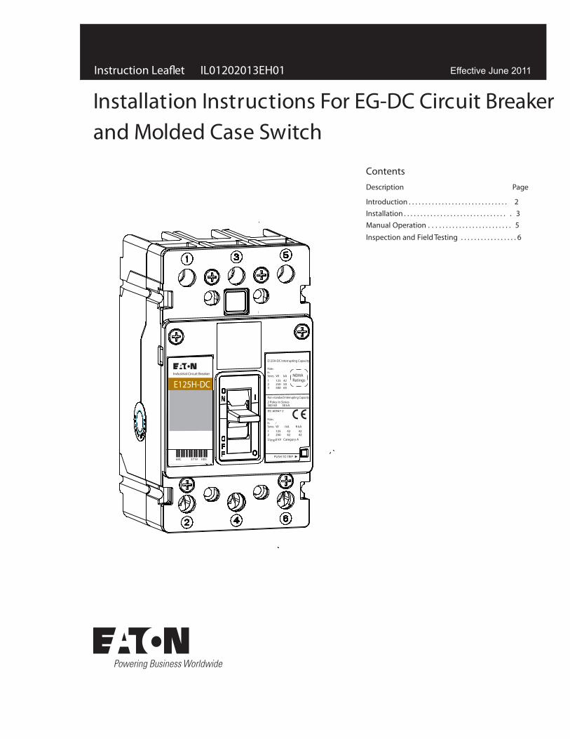
Installation Instructions For EG-DC Circuit Breakerand Molded Case Switch
H02
Effective June 2011
E125H-DC
68C 3719 H03
Industrial Circuit Breaker
E125H-DC Interrupting Capacity
PUSH TO TRIP
NEMARatings
kA425065
PolesInSeries123
V∂125250500
IEC 60947-2
› kA 42 42
fi kA 42 42
PolesInSeries12Uimp 6 kV Category A
⁄V∂125250
Non-standard Interrupting Capacity2 Poles In Series300 V∂ 50 kA
2
Instruction Leafl et IL01202013EH01 Installation Instructions For EG-DC Circuit Breakerand Molded Case Switch
EATON CORPORATION www.eaton.com
1. Introduction General Information
In this document, the term circuit breaker includes molded case switches. The E-frame Series G circuit breaker type ED-DC (Fig. 1) is rated 500 Vdc maximum and from 25A to 100A continuous current. (Refer to Table 1 for all available trip unit ratings.) The circuit breaker is listed in accordance with Underwriters Laboratories, Inc. Standard UL489. The type EG-DC circuit breaker is for use in grounded and ungrounded applications where multiple poles are connected in series (Figures 2-5) A 3-pole breaker may be wired as a 2-pole with rated voltage and interruption based on the number of poles wired
Table 1. Available Current Ratings.
Circuit Breaker Types Current Ratings
EG-DC 253035404550607080
Figure 2. Load Connected to Power Source. Grounded or Ungrounded Systems.
Power
Load
Power
Load
Breaker Breaker3 Pole 3 Pole
Load Connected to Power Source. Grounded or Ungrounded Systems.
Fig. 5-1
WARNINGDO NOT ATTEMPT TO INSTALL OR PERFORM MAINTENANCE ON EQUIP-MENT WHILE IT IS ENERGIZED. DEATH, SEVERE PERSONAL INJURY OR SUBSTANTIAL PROPERTY DAMAGE CAN RESULT FROM CONTACT WITH ENERGIZED EQUIPMENT. ALWAYS VERIFY THAT NO VOLTAGE IS PRESENT BEFORE PROCEEDING WITH THE TASK, AND ALWAYS FOLLOW GENERALLY ACCEPTED SAFETY PROCEDURES.
EATON IS NOT LIABLE FOR THE MISAPPLICATION OR MISINSTALLATION OF ITS PRODUCTS.
The user is cautioned to observe all recommendations, warnings, and cautions relating to the safety of personnel and equipment as well as all general and local health and safety laws, codes, and proce-dures.
Figure 1. Type EG-DC Series C DC Circuit Breaker
The recommendations and information contained herein are based on Eaton experience and judgement, but should not be considered to be all-inclusive or covering every application or circumstance which may arise. If any questions arise, contact Eaton for further information or instructions.
Fixed Thermal
90100
E125H-DC
68C 3719 H03
Industrial Circuit Breaker
E125H-DC Interrupting Capacity
PUSH TO TRIP
NEMARatings
kA425065
PolesInSeries123
V∂125250500
IEC 60947-2
› kA 42 42
fi kA 42 42
PolesInSeries12Uimp 6 kV Category A
⁄V∂125250
Non-standard Interrupting Capacity2 Poles In Series300 V∂ 50 kA
in series. This instruction lea�et (IL) gives procedures for installation and �eld testing of the types EG-DC Series G DC circuit breaker.
3
Instruction Leaflet Installation Instructions For EG-DC Circuit Breakerand Molded Case Switch
E ATON CORPORATION www.eaton.com
Figure 3. Load Isolated from Power Source. Grounded or Ungrounded Systems. If System Voltage Exceeds 300 Vdc, then Ungrounded Systems Only.
Figure 4. Load Connected to Power Source. Grounded or Ungrounded Systems.
Figure 5. Load Isolated from Power Source. Grounded or Ungrounded Systems. If System Voltage Exceeds 125 Vdc, then Ungrounded Systems Only.
Power
Load Power
Load
Breaker Breaker3 Pole 3 Pole
Load Isolated from Power Source.Grounded or Ungrounded Systems.If System Voltage Exceeds 300 Vdc.Then Ungrounded Systems Only.
Fig. 5-2
Breaker
Load
Power
Breaker
Load
Power
2 Pole 2 Pole
Load Connected to Power Source.Grounded or Ungrounded Systems.
Fig. 5-3
Breaker
Power
Load
2 Pole
Fig. 5-4
2. InstallationThe installation procedure consists of inspecting the circuit breaker and, as applicable, installing accessories, interphase barriers and terminals, mounting the circuit breaker, connecting the line and load conductors, torquing terminals, and attaching terminal shields. Circuit breakers, accessories,mounting hardware, and unmounted terminals may be supplied in separate packages. To install the circuit breaker, perform the following steps.
If required, internal accessory installation in any type of circuit breaker should be done before the circuit breaker is mounted and
2-1. Make sure that the circuit breaker is suitable for the intended installation by comparing name-plate data with existing ratings and system requirements. Inspect the circuit breaker for completeness,and check for damage before mounting.
2-2. Remove installed cover screws and cover.
CAUTIONWHEN REMOVED AND REINSTALLED, THREAD-FORMING SCREWS WILL TRY TO REFORM THE THREADS IN THE BASE . CARE SHOULD BE TAKEN EVERY TIME A THREAD-FORMING SCREW IS USED TO ENSURE THE SCREW STARTS IN THE ORIGINAL THREADS. DAMAGED THREADS CAN RESULT IN IMPROPER CIRCUIT BREAKER COVER RETENTION.
IL01202013EH01
4
Instruction Leaflet IL01202013EH01 Installation Instructions For EG-DC Circuit Breakerand Molded Case Switch
E ATON CORPORATION www.eaton.com
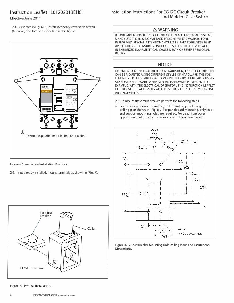
Figure 6. Cover Screw Installation Positions.
2-5. If not already installed, mount terminals as shown in (Fig. 7).
Figure 7. Terminal Installation.
TerminalBreaker
Collar
T125EF Terminal
WARNINGBEFORE MOUNTING THE CIRCUIT BREAKER IN AN ELECTRICAL SYSTEM, MAKE SURE THERE IS NO VOLTAGE PRESE NT WHERE WORK IS TO BE PERFORMED. SPECIAL ATTENTION SHOULD BE PAID TO REVERSE FEED APPLICATIONS TO ENSURE NO VOLTAGE IS PRESE NT. THE VOLTAGES IN ENERGIZED EQUIPMENT CAN CAUSE DEATH OR SEVERE PERSONAL INJ URY.
NOTICEDEPENDING ON THE EQUIPMENT CONFIGURATION, THE CIRCUIT BREAKER CAN BE MOUNTED USING DIFFERENT STYLES OF HARDWARE. THE FOL-LOWING STEPS DESCRIBE HOW TO MOUNT THE CIRCUIT BREAKER USING STANDARD HARDWARE. WHEN SPECIAL HARDWARE IS NEEDED (FOR EXAMPLE, WITH THE ELECTRICAL OPERATOR), THE INSTRUCTION LEAFLET DESCRIBI NG THE ACCESSORY ALSO DESCRIBES THE SPECIAL MOU NTING ARRANGEMENTS.
2-6. To mount the circuit breaker, perform the following steps:
a. For individual surface mounting, drill mounting panel using the drilling plan shown in (Fig. 8) . For panelboard mounting, only load end support mounting holes are required. For dead front cover applications, cut out cover to correct escutcheon dimensions.
Non-standard Interrupting Capacity2 Poles In Series300 V∂ 50 kA
2-4. As shown in Figure 6, install secondary cover with screws(6 screws) and torque as speci�ed in this �gure.
5
Instruction Leaflet IL01202013EH01Installation Instructions For EG-DC Circuit Breaker and Molded Case Switch
E ATON CORPORATION www.eaton.com
sories, make sure that accessory wiring can be reached when the circuit breaker is mounted.
NOTICELABELS WITH ACCESSORY CONNECTION SCHEMATIC DIAGRAMS ARE PROVIDED ON THE SIDE OF THE CIRCUIT BREAKER. A NOTE SHOULD BE MADE OF THE DIAGRAMS IF THE LABELS CANNOT BE SEEN WHEN THE CIRCUIT BREAKER IS MOUNTED.
d. Position circuit breaker on mounting surface.
e. Install circuit breaker mounting screws and washers. Tighten
CAUTIONWHEN ALUMINUM CONDUCTORS ARE USED, THE APPLICATION OF A SUITABLE J OINT COMPOUND IS RECOMMENDED TO REDUCE THE POSSIBILIT Y OF TERMINAL OVERHEATING. OVERHEATING CAN CAUSE NUISANCE TRIPPI NG AND DAMAGE TO THE CIRCUIT BREAKER .
2-7. Connect line and load conductors and accessory leads.
2-8. If required, install terminal shield on circuit breaker cover with mounting screws provided.
2-9. After the circuit breaker is installed, check all mounting hard-ware and terminal connecting hardware for correct torque loading. Torque values for line/load terminals are given in Table 2 and on the circuit breaker nameplate.
Table 2. Terminal Types
Terminal Catalog Number
Terminal Material Body
Screw Head Type
AWG Wire Range
Metric Wire Range
Wire Type
Torque Valuelb-in (N.m.)
T125EF Steel Slotted #14-3/0 2.5-95 Cu See Nameplate
3. Manual Operation and Thermal-Magnetic Adjustment Manual Operation
Manual operation of the circuit breaker is controlled by the circuit breaker handles and the PUSH-TO-TRIP button in the trip unit. The circuit breaker handle has three positions, two of which are shown on the cover with raised lettering to indicate ON and OFF. On the sliding handle barrier, ON, OFF, and trip. They are shown by a color-coded strip for each circuit breaker handle position: red for ON, white for tripped, and green for OFF, ON/OFF is also shown with the international symbols l/0 (Fig. 9
Figure 9. Circuit Breaker Manual Controls.
Circuit Breaker Reset
After an automatic or accessory initiated trip, or a manual PUSH-TO-TRIP operation, the circuit breaker is reset by moving the circuit breaker handle to the extreme OFF position.
NOTICEIN THE EVENT OF A THERMAL TRIP IN A THERMAL MAGNETIC TYPE TRIP UNIT, THE CIRCUIT BREAKER CA NNOT BE RESET UNTIL THE THERMAL ELEMENT IN THE TRIP UNIT COOLS. NO CIRCUIT BREAKER SHOULD BE RECLOSED UNTIL THE CAUSE OF TRIP IS K NOWN AND THE SITUATION RECTIFIED.
PUSH-TO-TRIP Button
The PUSH-TO-TRIP button checks the circuit breaker tripping func-tion and is used to periodically exercise the operating mechanism in thermal-magnetic trip units. The button is designed to be operated by a small screwdriver.
—ON—TRIP
—OFF(Reset)
InternationalSymbols
Handle Position Indicator Color - RedWhiteGreen
Push-to-TripButton
— ON
— OFF
ONTRIPOFF (Reset)
—
——
E125H-DC
68C 3719 H03
Industrial Circuit Breaker
E125H-DC Interrupting Capacity
PUSH TO TRIP
NEMARatings
kA425065
PolesInSeries123
V∂125250500
IEC 60947-2
› kA 42 42
fi kA 42 42
PolesInSeries12Uimp 6 kV Category A
⁄V∂125250
Non-standard Interrupting Capacity2 Poles In Series300 V∂ 50 kA
).c. make poles in series conenctions as required for system (refer to �g. 2-5).
6
Instruction Leaflet IL01202013EH01 Installation Instructions For EG-DC Circuit Breakerand Molded Case Switch
E ATON CORPORATION www.eaton.com
4. Inspection and Field TestingSeries G molded case circuit breakers are designed to provide years of almost maintenance-free operation. The following procedure describes how to inspect and test a circuit breaker in service.
Inspection
Circuit breakers in service should be inspected periodically. The inspection should include the following checks (4-1 through 4-7):
WARNINGBEFORE INSPECTI NG THE CIRCUIT BREAKER IN AN ELECTRICAL SYSTEM, MAKE SURE THE CIRCUIT BREAKER IS SWITCHED TO THE OFF POSITION AND THAT THERE IS NO VOLTAGE PRESE NT WHERE WORK IS TO BE PERFORMED. SPECIAL ATTENTION SHOULD BE PAID TO REVERSE FEED APPLICATIONS TO ENSURE VOLTAGE IS PRESE NT. THE VOLTAGES IN ENERGIZED EQUIPMENT CAN CAUSE DEATH OR SEVERE PERSONAL INJ URY.
CAUTIONMAKE SURE THAT CLEANING AGENTS OR SOLVENTS USED TO CLEAN THE CIRCUIT BREAKER ARE SUITABLE FOR THE J OB. SOME COMMERCIAL CLEANING AGENTS WILL DAMAGE THE NAME PLATES OR MOLDED PARTS.
4-1. Remove dust, dirt, soot, grease, or moisture from the surface of the circuit breaker using a lint-free dry cloth, brush, or vacuum cleaner. Do not blow debris into circuit breaker. If contamination is found, look for the source and eliminate the problem.
4-2. Switch circuit breaker to ON and OFF several times to be sure that the mechanical linkages are free and do not bind. If mechanical linkages are not free, replace circuit breaker.
4-3. With the circuit breaker in the ON position, press the PUSH TO-TRIP button to mechanically trip the circuit breaker. Trip, reset, and switch circuit breaker ON several times. If mechanism does not reset each time the circuit breaker is tripped, replace the circuit breaker.
4-4. Check base, cover, and operating handle for cracks, chipping, and discoloration. Circuit breakers should be replaced if cracks or severe discoloration is found.
4-5. Check terminals and connectors for looseness or signs of over-heating. Overheating will show as discoloration, melting, or blister-ing of conductor insulation, or as pitting or melting of conductor sur-faces due to arcing. If there is no evidence of overheating or loose-ness, do not disturb or tighten the connections. If there is evidence of overheating,terminations should be cleaned or replaced. Before reenergizing the circuit breaker, all terminations and cable should be refurbished to the condition when originally installed.
4-6. Check circuit breaker mounting hardware, tighten if necessary.
4-7. Check area where circuit breaker is installed for any safety haz-
types of chemicals can cause deterioration of electrical connections.
Field Testing
NEMA Standards.
7
Instruction Leaflet IL01202013EH01Installation Instructions For EG-DC Circuit Breakerand Molded Case Switch
E ATON CORPORATION www.eaton.com
Notes:
E�ective June 2011
Instruction Leaflet IL01202013EH01 Installation Instructions For EG-DC Circuit Breakerand Molded Case Switch
Eaton CorporationElectrical Group1000 Cherrington ParkwayMoon Township, PA 15108United States877-ETN-CARE (877-386-2273)Eaton.com
PowerChain Management is a registered trademark of Eaton Corporation.
All other trademarks are property of their respective owners.
The instructions for installation, testing, maintenance, or repair herein are provided for the use of the product in general commercial applications and may not be appropriate for use in nuclear applica-
to replace, amend, or supplement these instructions to qualify them for use with the product in safety-related applications in a nuclear facility.
The information, recommendations, descriptions, and safety nota-tions in this document are based on Eaton’s experience and judg-
al literature is published solely for information purposes and should not be considered all-inclusive. If further information is required, you should consult an authorized Eaton sales representative.
The sale of the product shown in this literature is subject to the terms and conditions outlined in appropriate Eaton selling policies or other contractual agreement between the parties. This literature is not intended to and does not enlarge or add to any such contract. The sole source governing the rights and remedies of any purchaser of this equipment is the contract between the purchaser and Eaton.
NO WARRANTIES, EXPRESSED OR IMPLIED, INCLUDING WARRANTIES OF FITNESS FOR A PARTICULAR PURPOSE OR MERCHANTABILITY, OR WARRANTIES ARISING FROM COURSE OF DEALING OR USAGE OF TRADE, ARE MADE REGARDING THE INFORMATION, RECOMMENDATIONS, AND DESCRIPTIONS CONTAINED HEREIN. In no event will Eaton be responsible to the purchaser or user in contract, in tort (including negligence), strict liability or otherwise for any special, indirect, incidental or conse-quential damage or loss whatsoever, including but not limited to damage or loss of use of equipment, plant or power system, cost of capital, loss of power, additional expenses in the use of existing power facilities, or claims against the purchaser or user by its cus-tomers resulting from the use of the information, recommendations and description contained herein.