Instruction Manual Farr Gold Series ® Dust Collector - GS1 Mini Customer: Location: Purchase Order: Local rep: Rep. phone: Edition: 1.0 - 05/11-2014 AIR POLLUTION CONTROL IOM14055 Camfil APC Ltd Unit C, Birch Business Park, Heywood, OL10 2SX United Kingdom Tel: +44 (0)1706 363820 europe.apc@camfil.com www.camfilapc.com/europe FARR GOLD SERIES ®
SECTION 300- OPERATION OF YOUR EQUIPMENT 300.1 System Operation 13300.2 Recommended Controller Settings 14
SECTION 400- PREVENTIVE MAINTENANCE 15400.1 Filter Elements 15400.2 Hopper 15400.3 Solenoid and Diaphragm Valves 15400.4 Control System 15400.5 Cleaning and Repair 15400.6 Pressure vessels 15400.7 Checking the Door Seal 16
SECTION 410- TROUBLESHOOTING 17
Farr Gold Series®
3
SECTION 100 - DEFINITIONS
m3/hActual m3 of gas per hour. The volume of gas flowing per hour at the operating temperature, pressure, elevation and composition.
Air-to-Cloth RatioThe ratio between air flowing through a dust collector and the m2 of filter area available (m3/m2 h). Sometimes referred to as the velocity (m/h) of air through the cloth.
BlindingBlockage in a fabric or media by dust that cannot be discharged by the cleaning mechanism, result-ing in a reduced gas flow and an increased pres-sure drop across the media. Once enough mate-rial has built up, airflow is severely restricted and the bags have to be cleaned or replaced.
BridgingMaterial handling problem characterized by the particulate forming a cavity over the discharge or opening of a hopper or storage vessel. Also, the accumulation of collected dust between two or more filter elements.
Clean Air PlenumThe dust collector area, through which gases are directed, located on the clean side of the filter media.
Collection EfficiencyThe measure of a dust collector’s ability to remove particulate from the inlet gas, typically expressed in percent or emission rate (mg per cubic meter).
Dew PointThe temperature at which condensation begins to form as the gas is cooled.
Differential PressureThe change in pressure or the pressure drop across a device. The difference between static pressures measured at the inlet and outlet of a device, Ref. Pressure Drop.
Dust Cake A dust build-up on the filter elements that increases the efficiency of the filter media.
Diaphragm ValveA compressed air valve operated by a solenoid valve that opens to allow a pulse to a row of filters.
Dust LoadingThe weight of solid particulate suspended in an air stream, usually expressed in mg per cubic meter.
EmissionsParticulate that escapes through or around a dust collector into the atmosphere.
Negative Pressure SystemA system where the fan is located after the dust collector on the clean air side, pulling air through the system.
Positive Pressure SystemA system with a fan located prior to a dust collector on the dirty side, pushing air through the system.
PrecoatMaterial added to the air stream at start-up to aid in establishing the initial dust cake on the filter media.
Pulse Duration (On-Time) The length of time a pulse lasts, generally described as the length of time the electric signal holds the solenoid pilot valve open (fixed at 150 ms).
Pause Time (Off-Time) Elapsed time between pulses in a dust collector cleaning system.
Solenoid Valve An electromechanical plunger device that is either “normally open” or “normally closed”. In use with a dust collector, it is for the relief of air pressure to activate a compressed air device such as a diaphragm valve.
Tube Sheet A steel plate on which the open end of the filter elements are connected. This wall separates the clean air and dirty air plenums of the dust collector.
Farr Gold Series®
4
SECTION 110 - INTRODUCTIONCongratulations on your selection of Camfil Air Pollution Control equipment! As the owner / operator of this equipment you have an impor-tant responsibility to see that it is operated and maintained in a safe manner. The unit will require moderate attention to keep it in good operating condition. This manual has been prepared to aid you in that effort. Throughout this manual, refer-ence may be made to various components, which may or may not be part of your particular system. They are included in the interest of fully describing typical systems with all available options.This manual covers the installation, operation and maintenance of the Farr Gold Series GSP1 Mini dust collector. This air cleaning equipment is used to eliminate dust contaminants from the environ-ment making the facility or plant a healthier and safer work place. This unit has been assembled using only quality materials and labor. This machine has been checked to make sure that it is operational for you at the time of installation.Prior to installing your equipment, thoroughly read and understand this manual. Locate all parts and ensure that nothing is missing, suffered shipping damage, or has been damaged during unloading. Familiarize yourself with each component of your system and its function using the contents of this manual as a guide. Refer to any local codes or ordinances relating to equipment of this type. They may affect the method or procedure used to install your system. Important! For safe and reliable results, assembling work, electrical installation, use, service and trouble-shooting should be performed by qualified personnel. Special training may also be necessary. Standards relating to the connection and use of dust collectors in hazardous areas must be taken into consideration, especially national standards for installation. Only trained personnel familiar with these standards should handle this type of dust collector.
IMPORTANT!
110.2 Conditions for Safe Use and StartUnless the conditions listed below are fulfilled it is not allowed to start the dust collector. • The unit is only approved for it’s intended use and can only be used safely for this. The intended use includes dust generating pro-cess and materials used. Any change with this needs to be approved by Camfil APC. The user is responsible for supplying Camfil APC with relevant information.• The dust collector is intended to be used as a part of a system. This system may not be started until it has been declared in conform-ity with relevant safety requirements. This includes risk assessment and an explosion protection plan if the system will handle explo-sive dust.NB! This is a minimum requirement each case must be treated individually, this is the responsibility of the plant owner/ operator.
110.1 Intended UseThe Camfil APC Farr Dust Collector is designed for collecting and filtering fume and non-explosive dry dust. N.B. To guarantee the correct function the dust collector must only be used accord-ing to its intended use and according to the instructions in this manual.
Do not discard this manual! It contains information, which when properly used, will insure proper operation, continued high performance and a long work life to your unit.
IMPORTANT! The GS1 Mini dust collector is shipped with castors for transportation. It is important that these are removed and the dust collector is bolted to the floor before operation.
Farr Gold Series®
110.3 Technical Data Filtration..................................... 99.99% on 0.5 micron and larger particles by weightOperating airflow........................ Max. 850 m3/hFilter area / filter cartridge.......... 120 m2 (1 x 30 m2) Filter material............................. Cellulose / Polyester HemiPleat Standard Green*Operating temperature............... - 20 ºC to + 40 ºC Process air (dry) temperature.... 0 ºC to +70 ºCEnvironment classes.................. C3 according to EN ISO 12944 Compressed air requirements.... See page 15, figure 220.2.2Compressed air connection........1” BSP Reservoir ConnectionVoltage supply............................ 230/400 V 3p, 50 Hz Protection class.......................... IP 55Power......................................... 1.1 KW/DOLWorking pressure....................... 0 kPa to - 2,5 kPa depending on airflow Marking...................................... CESound Power at 1m................... Casing break-out noise, average sound pres. level, free field 1m 64 dB(A) re 20 μPaWeight........................................ 262 KgDimensions................................ 569 x 696 x 2146 mm (W x L x H)
* Other cartridges might be used depending on application and suitability.
5
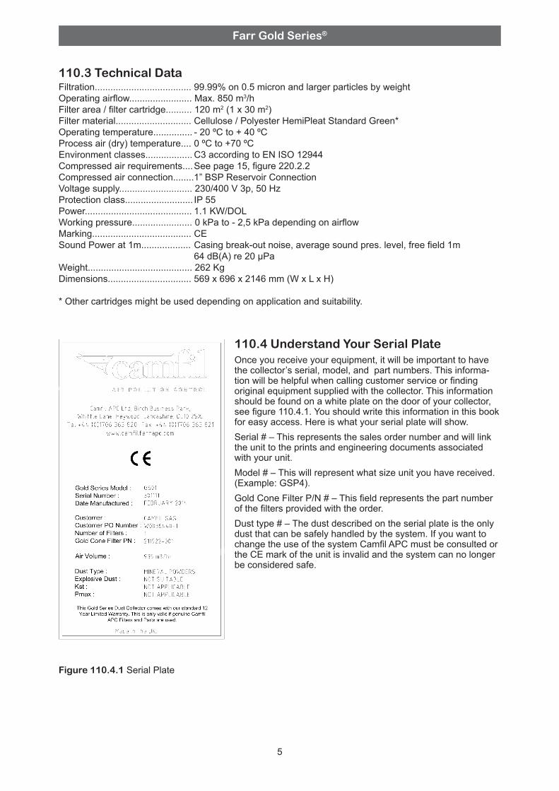
110.4 Understand Your Serial PlateOnce you receive your equipment, it will be important to have the collector’s serial, model, and part numbers. This informa-tion will be helpful when calling customer service or finding original equipment supplied with the collector. This information should be found on a white plate on the door of your collector, see figure 110.4.1. You should write this information in this book for easy access. Here is what your serial plate will show. Serial # – This represents the sales order number and will link the unit to the prints and engineering documents associated with your unit.Model # – This will represent what size unit you have received. (Example: GSP4).Gold Cone Filter P/N # – This field represents the part number of the filters provided with the order.Dust type # – The dust described on the serial plate is the only dust that can be safely handled by the system. If you want to change the use of the system Camfil APC must be consulted or the CE mark of the unit is invalid and the system can no longer be considered safe.
Figure 110.4.1 Serial Plate
Farr Gold Series®
SECTION 120 - SAFETY PRECAUTIONS
6
120.1 Safety PrecautionsCamfil APC relies on the skills and expertise of its customer and any consulting engineers and/or installing contractors hired by that customer to properly install the dust collection system of which Camfil APC equipment is a part. Read this manual thoroughly and comply with the precautionary statements relative to worker safety. Precautions must be taken to ensure that all electrical/air con-nections and regulation devices are installed and operating properly.The GS1 Mini dust collector is shipped with castors for transportation. It is important that these are removed and the dust collector is bolted to the floor before operation.
120.2 Understand Signal Words and SymbolsThe symbols shown below appear on the equip-ment to alert you of potential hazards. When you see these symbols you must read, understand, and heed the information that accompanies them.
DANGER!
WARNING!
Indicates an imminently hazardous situation, which, if not avoided, may result in death or serious injury.
Indicates a potential hazardous situation, which, if not avoided, may result in death or serious injury.
WARNING!Do not attempt to operate or maintain this piece of equipment until you have read and thoroughly understood all of the safety in-formation contained in this manual. All such information must be taken seriously. This piece of equipment contains moving parts and potential pinch points, which can cause seri-ous injury or death. If you do not understand any subjects in this manual, seek assistance from your supervisor before operating this equipment. DO NOT attempt to operate this equipment without factory-installed guards. Replace damaged guards.
120.3 Warning Decals and GuardsThis piece of equipment contains several war-ning decals located in many different locations. It is the owner/operator’s responsibility to maintain the integrity of these decals and to ensure that all operators of the equipment are aware of them and understand their meaning. Replacement decals are available free of charge from your Camfil Ser-vice Representative, or by contacting Camfil APC. Part numbers for these decals are listed in the spare parts list in section 600. This piece of equipment may contain one or more safety guards to protect the operator(s) from injury. It is the owner/operator’s responsibility to maintain the integrity of these guards and ensure that they are in place when the equipment is in operation.
120.4 Lock-out/Tag-out RequirementsEmployers shall establish a program and utilize procedures for affixing appropriate lock-out/ tag-out devices to energy isolating devices and to otherwise disable machines or equipment to prevent unexpected energizing, start-up, or release of stored energy in order to prevent injury to employees.Before inspecting or servicing this equipment perform an approved Lock-out/Tag-out procedure on the electrical service, the compressed air (or other gas) supply, or any other energy source.
Indicates hazards as-sociated with compressed air sources.
Indicates a potential hazardous situation, which, if not avoided, may result in minor or moderate injury and or property damage.
Indicates the presence of an electrical power source, which could result in death, personal and/or property damage.
Farr Gold Series®
7
SECTION 130 - RECEIVING YOUR EQUIPMENT130.1 The Purchaser’s ResponsibilityA visual inspection of your equipment should be performed before it is removed from the truck. Dents, scratches and other damage should be noted and photographed. The structural integrity of the housing will be adversely affected by dents. Camfil APC should immediately be notified of any structural damage to your equipment. It is the purchaser’s responsibility to file shortage reports and damage claims with the carrier. The carrier is responsible for any damage to the equipment while it is in transit unless specific arrangements are made otherwise.Besides a common set of hand tools, a crane, fork-lift and/or chain-fall will be required to position the dust collector.Camfil APC must rely on the skill and expertise of its customers and the customer’s installation con-tractor to ensure that all electrical connections are made correctly and air connections and regulation devices are installed and operating properly.
130.2 Uncrating and InspectionEach Farr Gold Series GS1 Mini dust collector is usually shipped on a palletUse extreme care when handling the unit and components. Careless handling can damage delicate parts or affect assembly alignments. Compare the number of items received against the carrier’s Bill of Lading. Inspect all items for apparent damage. Immediately report any shortages or obvious damage to the carrier and to your local Camfil APC representative.When all skids are completely unpacked, check all items received against the material list or the packing list (if any) sent with the shipment. Further inspect the unit and components for hidden damage. Again, report any shortages or damage to the carrier and to your local Camfil APC Representative.Do not return any damaged components without first contacting your Camfil APC Representative to obtain Returned Goods Authorization (RGA). Carefully inspect all packing material so that small parts are not inadvertently discarded.
IMPORTANT! The GS1 Mini dust collector is shipped with castors for transportation. It is important that these are removed and the dust collector is bolted to the floor before operation.
WARNING!Risk of personal injury and/or product damages! The unit is stabile but if it is hit by a heavy object it can fall over unless it is placed on a solid foundation and anchored.
Attach the unit to the foundation.
SECTION 200 - INSTALLATION OF YOUR EQUIPMENT200.1 FoundationThe unit must be placed on a suitable foundation. The foundation must be level and of sufficient strength to hold the weight of the unit (see technical data for weight data).
Farr Gold Series®
8
SECTION 220 - FIELD UTILITY CONNECTIONS
220.1 Electric connections
WARNING! Failure to perform an approved Lock-out/Tag-out procedure may result in a sudden release of energy resulting in property damage, personal injury or death! Ensure that the circuit you are working with is off before you make these or any other electrical connections. Serious injury may result if you do not take proper safety precautions!
Electrical connection of incoming power shall be done to the input terminals on the main switch and the PE connection terminal next to the main switch.
IMPORTANT! • The compressed air supply pressure has to be 6-7 Bar. • The compressed air shall have a dew point (+2°C is recommended) below the minimum temperature at which the system is ment to be used. • The compressed air supply must be both oil and water free. • Improper air pressure or contamination in the compressed air can result in cleaning valve failure, poor cleaning, and poor filter performance.
• Purge compressed air lines to remove debris before connecting to the compressed air manifold. • Quick couplings restrict the air too much and are not recommended. • Turn off and bleed off compressed air supply before doing any service work. • Do not pressurise the system if the air temperature is below the minimum operating temperature.
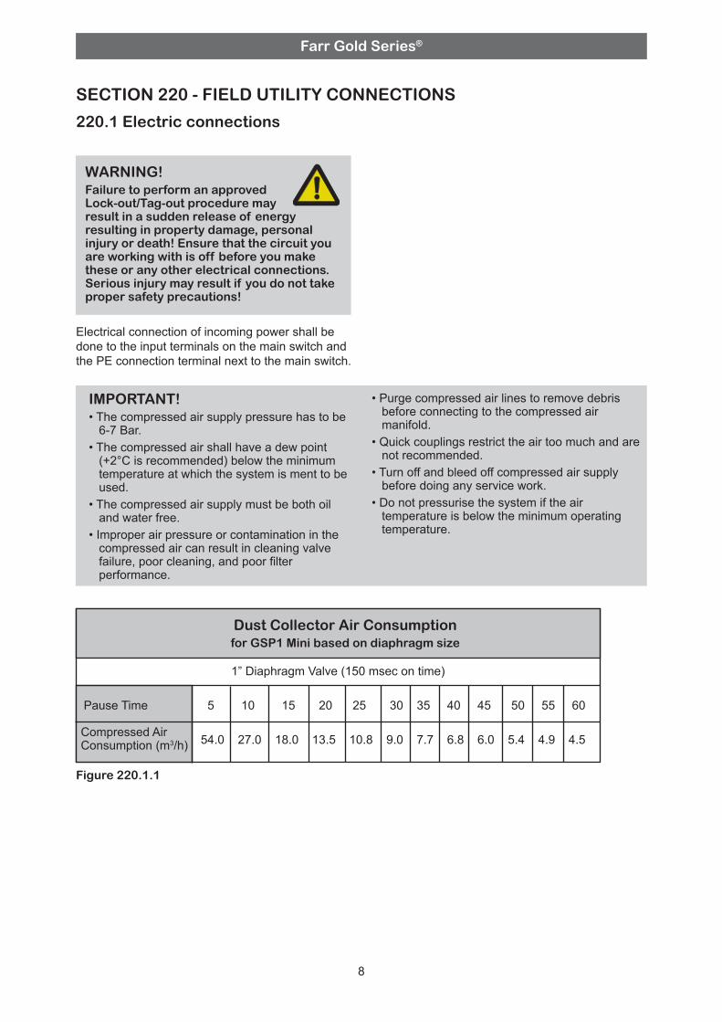
Dust Collector Air Consumption for GSP1 Mini based on diaphragm size
230.1 Step by Step Instructions1. 1. Shut down the process or dust generating operation to which the dust collector is installed. Continue the operation of the unit for 20 minutes to assure good removal of the collected dust. Break the electric power and shut off and bleed the com-pressed air from the tank. If required, perform an approved lock/tag out procedure. Empty the dust container.2. Open the access door at the front of the unit, swinging it out of the way. 3. Unlatch the clamp bars as shown in Figures 230.1.1-230.1.4. • With your left hand, rotate the right-hand clamp bar clockwise or up and pull it toward you, until its locking tab clears the rectangular cut-out on the left-hand clamp bar. • With your right hand, rotate the left-hand clamp bar counter-clock-wise or up and push it away from you until its locking tab clears the rectangular cut-out on the right-hand clamp bar.• Rotate the right-hand clamp bar counterclock-wise or down, until it is clear of the cartridge removal path – Figure 230.1.2. • Rotate the left-hand clamp bar clockwise or down, until it is clear of the cartridge removal path also – Figure 230.1.3. • Figure 230.1.4 shows the cartridges ready to be removed.4. Remove the dirty filter cartridges by sliding them off the clamp bar channels. Clean the surface of the tube sheet in the areas where the filter gasket forms a seal.
SECTION 230 - FILTER INSTALLATION/REPLACEMENTNew units ship with filter cartridges installed. We have many types of replacement filters available for a wide range of applications. Refer to section 420 - GSP4 Spare Parts for replacement filter and various parts identification. Care should be taken to make sure the correct Camfil APC original equipment replacement filters are used to insure continued satisfactory performance of the unit. Please contact Camfil APC for genuine replacement parts.
5. Remove a new cartridge from the shipping carton, taking care not to cut or otherwise damage the filter media. • Make sure the clamp bar handles are fully opened and will not interfere with the cartridge during installation - Figure 230.1.5. • Grasp the new cartridge by the top metal pan and set it onto the clamp bar channels. • Holding the cartridge level, slide it forward, pushing on the cartridge pan, do not push the media, taking care not to drag the gasket along the tube sheet. • Push the cartridge in just far enough to leave room for the next cartridge to rest on the clamp bar channels. • Repeat steps 4 and 5 until the row is full.6. To seal the new cartridges, repeat the instruc-tions in step 3 in reverse order. With your left hand, rotate the left-hand clamp bar counter-clock-wise or up to between 80° and 90°. While pushing the left- hand clamp bar away from you, rotate the right-hand clamp bar clockwise or up, with your right hand. Insert the locking tab on the left-hand clamp bar when it lines up with the rectangular cut-out on the right-hand clamp bar. Release the left-hand clamp bar. With both hands rotate the right-hand clamp bar clockwise or up and pull it toward you, until the locking tab inserts into the rectangular cut-out on the left-hand clamp bar – Figure 330.1.2. The clamp bars must be bent slightly if the locking tabs do not stay inserted in the rectangular cutouts.7. Repeat the above procedure until all the rows of cartridges are full.
Figure 350.4 - Clamp Bars Open Figure 350.3 Figure 230.1.3
Farr Gold Series®
230.2 Filter Replacement Minimizing Dust ContaminationIf you wish to reduce dust contamination around the unit it is possible to use the following procedure. Wear suitable personal protection and acquire a plastic bag to fit the cartridges (610 x 1020 mm).
Figure 230.2.1 - Open door
Figure 230.2.2 - Put the plastic bag under the used cartridge
Figure 230.2.3 - Pull the bag up over the cartridge
Figure 230.2.4 - Open the clamps
11
Farr Gold Series®
Figure 230.2.5 - Pull out the cartridge
Figure 230.2.6 - Place the used cartridge in the box that came with the replacement cartridge
Figure 230.2.7 - Close the box
12
Farr Gold Series®
13
SECTION 300 - OPERATION OF YOUR EQUIPMENT
300.1 Cleaning System ComponentsHEADER (COMPRESSED AIR PRESSURE RESERVOIR)A header is provided with a 1 in. NPT coupling at each end. Supply the header with clean, dry compressed air between 0,62 and 0,72 MPa (6 and 7 Bar). The air supply line should be equipped with a manual shut-off valve, a filter/separator, an air regulator and a pressure gauge, all located near the unit.
SOLENOID/DIAPHRAGM VALVESSolenoid-operated valves on the collector operate one (1) diaphragm valve each. Diaphragm valves on the collector operate one (1) pulsejet blowpipe each. The automatic timer control energizes the solenoid, which causes the plunger in the solenoid to move. When the plunger moves, air in the upper chamber of the solenoid is released to the atmos-phere. The resulting difference in air pressure between the upper chamber and the compressed air reservoir allows the diaphragm valve to open. This allows the air in the header to be released into the pulsejet blowpipes. The size of the diaphragm valves is 1”. See Section 420 - GSP4 Spare Parts for the size of diaphragm valves on your collector.
WARNING! Risk of personal injury! Use caution when working near an operating collector. Wear appropriate ear and eye protection! Hearing damage can result from high noise levels generated during filter cleaning or “pulsing” and collected debris, near the diaphragm valve discharge, may be-come a projectile, creating the potential for eye injury. Do not operate with access doors open!
PULSEJET BLOW PIPEEach pulsejet blowpipe contains one (1) nozzle for each cartridge. These nozzles are positioned above, and directed into, the opening of the filter cartridge. As the pulse of air reaches the nozzle, it is accelerated through the smaller diameter. The resulting shock wave travels down the length of the inside of the filter cartridge, dislodging the dust from the filter cartridge.
Figure 300.3.1 - Pulse jet cleaning components
filter cartridge
dust dust
pulsing air
control system
diaphragm valveheader (compressed air reservoir)puls-jet
blowpipenozzle
Farr Gold Series®
14
300.2 Recommended Controller SettingsPlease refer to Goyen Electronic Sequencer 10 Series Manual for recommended controller settings.
Farr Gold Series®
SECTION 400 - PREVENTIVE MAINTENANCE
Your Farr Gold Series PS1 Mini dust collection system requires very little maintenance to achieve maximum life and efficiency. The following items should be periodically serviced:
400.1 Filter ElementsPressure drop across Gold Cone filter elements normally increases rather rapidly when the filter elements are new and clean, but then climbs much more slowly throughout the rest of their service life. Typically, when the Gold Cone elements cannot be cleaned below a differential of 1,5 kPa or greater, they have reached the end of their service life and require replacement. Other indications for replacement are cart-ridges that have been in service over 2 years or cartridges that have been damaged by moisture, high heat, or other perilous conditions.
400.2 HopperAt the start/end of each shift, check the discharge container at the bottom of the unit. Dispose of any waste accumulation according to federal, state and local environmental regulations. Under no circumstances should the hopper be used to store collected material. Empty and replace full collection containers frequently. Do not over fill containers, as this will inhibit performance of the collector.
400.3 Solenoid and Diaphragm ValvesThe solenoid and diaphragm valves may require periodic maintenance depending on the quality of the compressed air supplied to the unit. Check each valve periodically to see that it is operating properly and if required.
WARNING! Risk of personal injury! • Use protective goggles, breathing mask and gloves when doing servi-cing and repairing work inside the system, especially when replacing the filter cartidges and emptying the dust container. • Before doing any service work, clean the working place and all surrounding areas. • Avoid contact or exposure to dust as much as possible during servicing or maintenance. • Shut-off and bleed compressed air supply before servicing any compressed air components. • Disconnect electrical power before servicing. • The Control Box must not be opened or be disconnected from cables if there is explosive dust in the atmosphere or dust cover on the boxes. In that case the boxes must be cleaned. • If the Minimum Ignition Energy, MIE, of the dust is less than 10 mJ, the service personnel must use shoes and other clothes specially designed to be used in explosion hazardous areas. Tools used for service works on the dust collector then also must be approved for explo-sion hazardous areas.
15
400.4 Control SystemThe automatic timer control does not require any routine maintenance. Check periodically to verify that the board is operating properly and the user-defined settings have not been tampered with. Dirt and moisture can damage the timer board. Check the enclosure periodically to ensure that no condensation is forming on the inside and that dust has not collected on the circuit board or inside the enclosure. Refer to separate instruction manual regarding the Control System.
400.5 Cleaning and RepairThe external and internal surfaces of the unit should be treated as any other painted metal surface subject to corrosion. Examine the unit for any damage to the surface coating and repair as necessary. Keep the external surfaces clean to prevent the possibility of hidden damage occurring. Periodic application of a quality automotive wax will prolong the life of painted surfaces and make them easier to clean.
400.6 Pressure vessels Drain condensate periodically, as moisture will damage the filter media. Verify periodically that the operating pressure is between 0,62 and 0,72 MPa (6 and 7 Bar). Inspect the reservoir for damage or corrosion. If you find significant damages or corrosion replace the tank.
SAFETY AND WARNING! (Compressed air tank(s)) Risk of personal injury! • Never attempt to disconnect or remove any connecting component of the pressurized system before bleeding off pressure and performing lock-out / tag-out procedures on the pressure source. • Do not alter, add to, or weld on to the reservoir. This is strictly forbidden! Doing so may cause irreparable damage and weaken the integrity of the vessel, thus causing an explosion hazard. • Do not exceed 0,82 MPa (8,2 bar) in pressure. • In case of fire, immediately depressurize reservoir. • Replace reservoir if it has been exposed to temperatures above 93,3 ºC (200 ºF). • Use the reservoir for its intended purpose only, in Camfil APC Dust Collection Systems. Misuse of the reservoir may cause injury or death. • A damaged reservoir must not be pressurized until it has been appraised by a qualified pressure vessel inspector. Never attempt to repair a damaged reservoir.
Farr Gold Series®
400.7 Checking the Door Seal
16
Door Adjustment Instructions
Check door gasket compression by consecutively closing and clamping door gasket onto a 100 x 200 mm strip of standard copy paper, first at the top, then middle, and then lower section of the handle side. Make sure paper is inserted so that gasket compresses against paper. A properly compressed gasket should not allow paper to be removed, when pulling paper laterally with moderate force. Do not use excessive force, as this will cause the paper to tear and/or the gasket to roll. Increase door gasket compression only when test fails.
Instructions for Increasing Door Gasket Compression
Figure 400.10.4 - Use either 1.5 mm. Or 3 mm shim (the unit comes with 2 of each)
Figure 400.10.5 - Loosen bolts and insert one shim
Figure 400.10.1 Figure 400.10.2
Figure 400.10.3
Farr Gold Series®
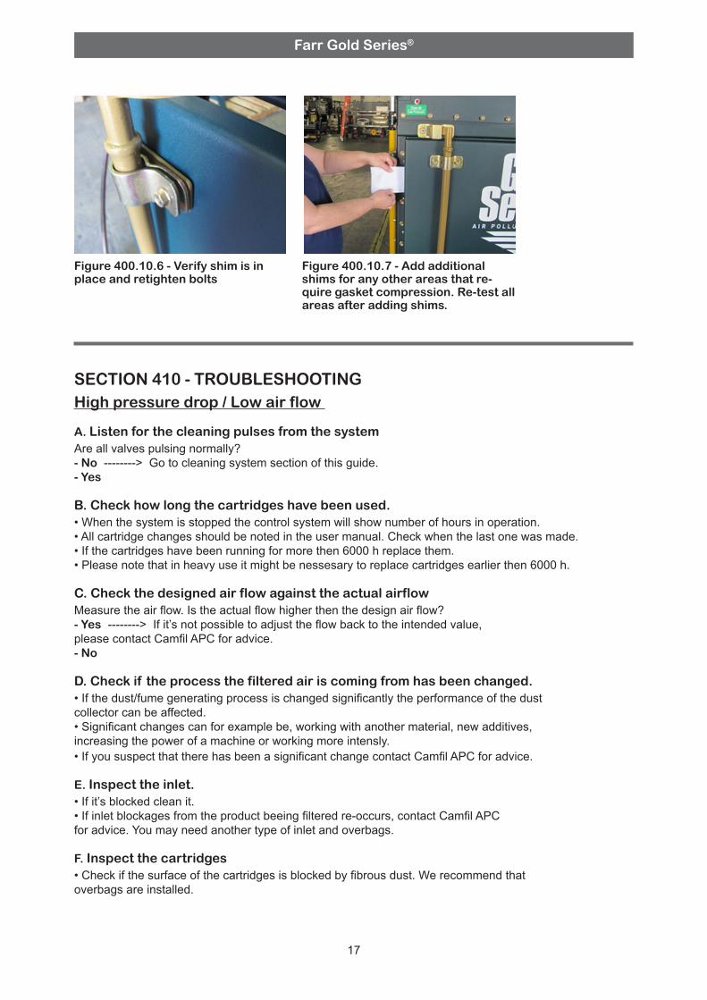
Figure 400.10.6 - Verify shim is in place and retighten bolts
Figure 400.10.7 - Add additional shims for any other areas that re-quire gasket compression. Re-test all areas after adding shims.
17
SECTION 410 - TROUBLESHOOTINGHigh pressure drop / Low air flow
A. Listen for the cleaning pulses from the system Are all valves pulsing normally? - No --------> Go to cleaning system section of this guide. - Yes
B. Check how long the cartridges have been used. • When the system is stopped the control system will show number of hours in operation. • All cartridge changes should be noted in the user manual. Check when the last one was made. • If the cartridges have been running for more then 6000 h replace them. • Please note that in heavy use it might be nessesary to replace cartridges earlier then 6000 h.
C. Check the designed air flow against the actual airflow Measure the air flow. Is the actual flow higher then the design air flow? - Yes --------> If it’s not possible to adjust the flow back to the intended value, please contact Camfil APC for advice. - No
D. Check if the process the filtered air is coming from has been changed. • If the dust/fume generating process is changed significantly the performance of the dust collector can be affected. • Significant changes can for example be, working with another material, new additives, increasing the power of a machine or working more intensly. • If you suspect that there has been a significant change contact Camfil APC for advice.
E. Inspect the inlet. • If it’s blocked clean it. • If inlet blockages from the product beeing filtered re-occurs, contact Camfil APC for advice. You may need another type of inlet and overbags.
F. Inspect the cartridges • Check if the surface of the cartridges is blocked by fibrous dust. We recommend that overbags are installed.
Farr Gold Series®
18
A. Check that the compressed air supply is connected and supplying 0,62 - 0,72 MPa (6 - 7 Bar).
B. Check that the compressed air drier is working and that the dew point is 2 C or less.
C. Verify that the supply pipe is at least ½” (R15) and that no restrictions for example quick couplings are used.
D. Verify that the supply has sufficent capacity. Air consumption depends on valve size and pulsing frequency.
E. If one or more valves are closing slowly or making abnormal noice. • This problem is typically caused by contaminated compressed air. Make sure that the air supply is filtered. • Bleed of the pressure. Remove the cover from the pulse-jet valve. Examine the membrane for damage and if nessesary remove any contaminants, especially from the bleed hole in the membrane. • Carefully reassemble the cover, making sure that the closing spring is in place. • Remove the pilot valve body from the STR and disassemble the valve. • Clean the inside in the same way as the pulse-jet valve. • If the problem re-occurs it may be nessesary to clean tanks and pipes by blowing them with compressed air. • If one ore more valves dosen’t clean at all. Go to the controll system problems section.
Cleaning system problems
WARNING! Risk of personal injury! Close supply valves and bleed the pressure from the compressed air tanks before any components of the cleaning system are removed or opened.
G. If the dust collector is sited outside or in a unheated space. • Check if the dust inside the collector is agglonomerating. • It is recommendable to install a off line damper, in the duct leading to the collector. This will close when the collector is out of operation and prevent natural draft that can cause condensation.• We recommend that the collector is pre-heated with clean air for a short while at the start up before dust load is applied. • We also recomend that the collector is flushed with clean air a while before shut down. • If the problems continue we recommend that the unit is moved to a heated space or insulated.