23
Instruction manual Alfa Laval ETHERNET weighing module Original manual ESE03516 Date of issue: 2017-08 First published: 2017-08
Instruction manual
Alfa Laval ETHERNET weighing module
Original manual
ESE03516 Date of issue: 2017-08
First published: 2017-08
Page: 2
1) Contents
1) Contents ......................................................................................................................................................... 2 2) Introduction ..................................................................................................................................................... 3
2.1 Introduction ............................................................................................................................................... 3 2.2 EtherNetIP specification............................................................................................................................ 3 2.3 ATEX (Ex) specification ............................................................................................................................ 3
3) Data Exchange ............................................................................................................................................... 4 3.1 EtherNetIP communication ....................................................................................................................... 4 3.2 Data formats ............................................................................................................................................. 5
3.2.1 Unsigned integer format (16 bit) ......................................................................................................... 5 3.2.2 Signed integer format (32 bit) ............................................................................................................. 5
3.3 Scaling ...................................................................................................................................................... 6 3.4 Measurement time .................................................................................................................................... 6 3.5 Filtering ..................................................................................................................................................... 6
4) Data Processing ............................................................................................................................................. 7 4.1 Zeroing, calibration and weight calculation ............................................................................................... 7
4.1.1 Zeroing of weighing system ............................................................................................................... 7 4.1.2 Corner calibration of weighing system ............................................................................................... 7 4.1.3 Calculation of uncalibrated system weight ......................................................................................... 8 4.1.4 System calibration of weighing system .............................................................................................. 8
5) Installation of System ..................................................................................................................................... 9 5.1 Checklist during installation ...................................................................................................................... 9
6) Hardware Description ................................................................................................................................... 10 6.1 4X50 overview ........................................................................................................................................ 10 6.2 4X50 front panel description ................................................................................................................... 10
6.2.1 Connection of power ........................................................................................................................ 11 6.2.2 Connection of loadcells .................................................................................................................... 11 6.2.3 Ethernet connector ........................................................................................................................... 11 6.2.4 SW1 settings .................................................................................................................................... 11 6.2.5 SWE settings .................................................................................................................................... 11 6.2.6 Light Emitting Diodes (LEDs) ........................................................................................................... 12
6.3 Hardware Selftest ................................................................................................................................... 13 6.4 Update times ........................................................................................................................................... 13
7) Appendices ................................................................................................................................................... 14 7.1 Appendix A – Setup ................................................................................................................................ 14 7.2 Appendix B – Allen Bradley connection .................................................................................................. 14 7.3 Appendix C – Omron connection ............................................................................................................ 14 7.4 Appendix D – Internal Features .............................................................................................................. 14
7.4.1 4050 Ethernet module ...................................................................................................................... 14 7.4.2 SW2 settings .................................................................................................................................... 15 7.4.3 Light Emitting Diodes (LEDs) ........................................................................................................... 15 7.4.4 4040 communication module ........................................................................................................... 15 7.4.5 SW2 settings .................................................................................................................................... 15 7.4.6 Jumper settings ................................................................................................................................ 16 7.4.7 Light Emitting Diodes (LEDs) ........................................................................................................... 16
7.5 Appendix E – Status Codes .................................................................................................................... 17 7.6 Appendix F – Download of new software ............................................................................................... 18
7.6.1 Download procedure ........................................................................................................................ 18 8) How to contact Alfa Laval Kolding A/S ......................................................................................................... 22 9) EC Declaration of Conformity ....................................................................................................................... 23
Page: 3
2) Introduction
2.1 Introduction
This document describes the use of a 4X50 Ethernet system unit from Alfa Laval A/S. The 4X50 system unit consists internally of a 4050 Ethernet module (with the software listed on the front page) and a 4040 communication module.
The 4X50system unit is connected to X loadcells (1-4). With the program specified on the front page, the 4X50 Ethernet unit is capable of transmitting weight and status for up to 4 loadcells in a single telegram.
It is possible to connect the 4X50 Ethernet unit to an EtherNetIP network, where it will act as a slave. It will then be possible from the EtherNetIP master to read status and weight for each of the connected loadcells. Functions as zeroing, calibration and calculation of system weight(s) must be implemented outside the 4X50 in the EtherNetIP master.
By use of DIP-switches it is possible to select measurement time and include one of 15 different FIR filters, which will be used to filter the loadcell signals.
Exchange of data between master and slave takes place as described in the following.
Note: The illustrations and specifications contained in this manual were effective at the date of
printing. However, as continuous improvements are our policy, we reserve the right to alter or
modify any unit specification on any product without prior notice or any obligation.
2.2 EtherNetIP specification
The EtherNetIP unit confirms with the following EtherNetIP specifications:
Protocol: EtherNetIP
Media: Ethernet
Module type: Slave(/Target)
Communication settings 10MB/s, Half duplex
IP-Address: Fixed (default: 192.168.1.199)
Ethernet connection: RJ45/Cat5
System setup: EEEthSetup software
Software download: RS232 terminal interface
2.3 ATEX (Ex) specification
IMPORTANT: Instrumentation (the 4X50A) must be placed outside the hazardous zone if the load cells are used in hazardous ATEX (Ex) area. Furthermore, only ATEX certified load cells and instrumentation can be used in ATEX applications.
Page: 4
3) Data Exchange
3.1 EtherNetIP communication
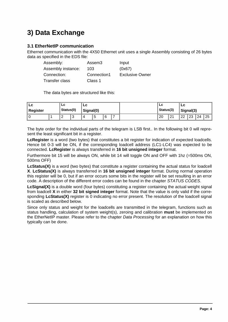
Ethernet communication with the 4X50 Ethernet unit uses a single Assembly consisting of 26 bytes data as specified in the EDS file:
Assembly: Assem3 Input
Assembly instance: 103 (0x67)
Connection: Connection1 Exclusive Owner
Transfer class Class 1
The data bytes are structured like this:
Lc
Register
Lc
Status(0)
Lc
Signal(0)
Lc
Status(3)
Lc
Signal(3)
0 1 2 3 4 5 6 7 20 21 22 23 24 25
The byte order for the individual parts of the telegram is LSB first.. In the following bit 0 will repre-sent the least significant bit in a register.
LcRegister is a word (two bytes) that constitutes a bit register for indication of expected loadcells. Hence bit 0-3 will be ON, if the corresponding loadcell address (LC1-LC4) was expected to be connected. LcRegister is always transferred in 16 bit unsigned integer format.
Furthermore bit 15 will be always ON, while bit 14 will toggle ON and OFF with 1hz (=500ms ON, 500ms OFF)
LcStatus(X) is a word (two bytes) that constitute a register containing the actual status for loadcell X. LcStatus(X) is always transferred in 16 bit unsigned integer format. During normal operation this register will be 0, but if an error occurs some bits in the register will be set resulting in an error code. A description of the different error codes can be found in the chapter STATUS CODES.
LcSignal(X) is a double word (four bytes) constituting a register containing the actual weight signal from loadcell X in either 32 bit signed integer format. Note that the value is only valid if the corre-sponding LcStatus(X) register is 0 indicating no error present. The resolution of the loadcell signal is scaled as described below.
Since only status and weight for the loadcells are transmitted in the telegram, functions such as status handling, calculation of system weight(s), zeroing and calibration must be implemented on the EtherNetIP master. Please refer to the chapter Data Processing for an explanation on how this typically can be done.
Page: 5
3.2 Data formats
The EtherNetIP communication can transfer data in the following three data formats. Please refer to other literature for further information on these formats as it is outside the scope of this docu-ment.
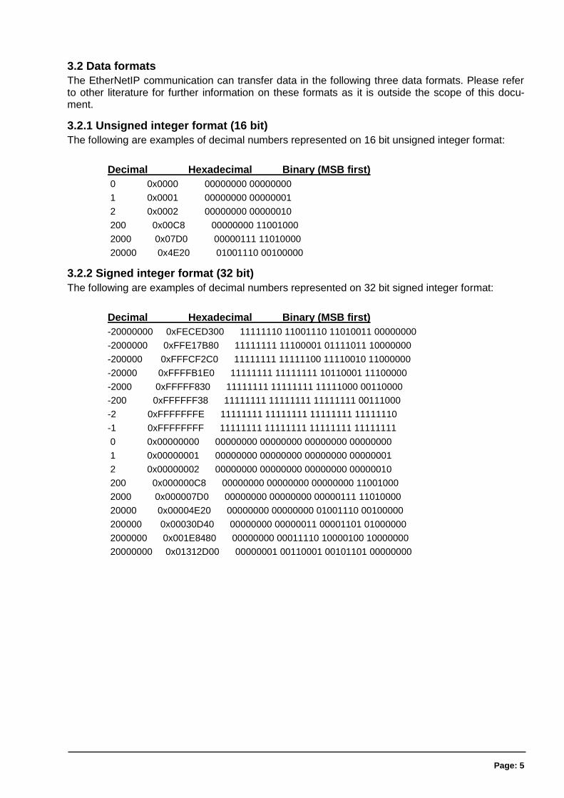
3.2.1 Unsigned integer format (16 bit)
The following are examples of decimal numbers represented on 16 bit unsigned integer format:
Decimal Hexadecimal Binary (MSB first)
0 0x0000 00000000 00000000
1 0x0001 00000000 00000001
2 0x0002 00000000 00000010
200 0x00C8 00000000 11001000
2000 0x07D0 00000111 11010000
20000 0x4E20 01001110 00100000
3.2.2 Signed integer format (32 bit)
The following are examples of decimal numbers represented on 32 bit signed integer format:
Decimal Hexadecimal Binary (MSB first)
-20000000 0xFECED300 11111110 11001110 11010011 00000000
-2000000 0xFFE17B80 11111111 11100001 01111011 10000000
-200000 0xFFFCF2C0 11111111 11111100 11110010 11000000
-20000 0xFFFFB1E0 11111111 11111111 10110001 11100000
-2000 0xFFFFF830 11111111 11111111 11111000 00110000
-200 0xFFFFFF38 11111111 11111111 11111111 00111000
-2 0xFFFFFFFE 11111111 11111111 11111111 11111110
-1 0xFFFFFFFF 11111111 11111111 11111111 11111111
0 0x00000000 00000000 00000000 00000000 00000000
1 0x00000001 00000000 00000000 00000000 00000001
2 0x00000002 00000000 00000000 00000000 00000010
200 0x000000C8 00000000 00000000 00000000 11001000
2000 0x000007D0 00000000 00000000 00000111 11010000
20000 0x00004E20 00000000 00000000 01001110 00100000
200000 0x00030D40 00000000 00000011 00001101 01000000
2000000 0x001E8480 00000000 00011110 10000100 10000000
20000000 0x01312D00 00000001 00110001 00101101 00000000
Page: 6
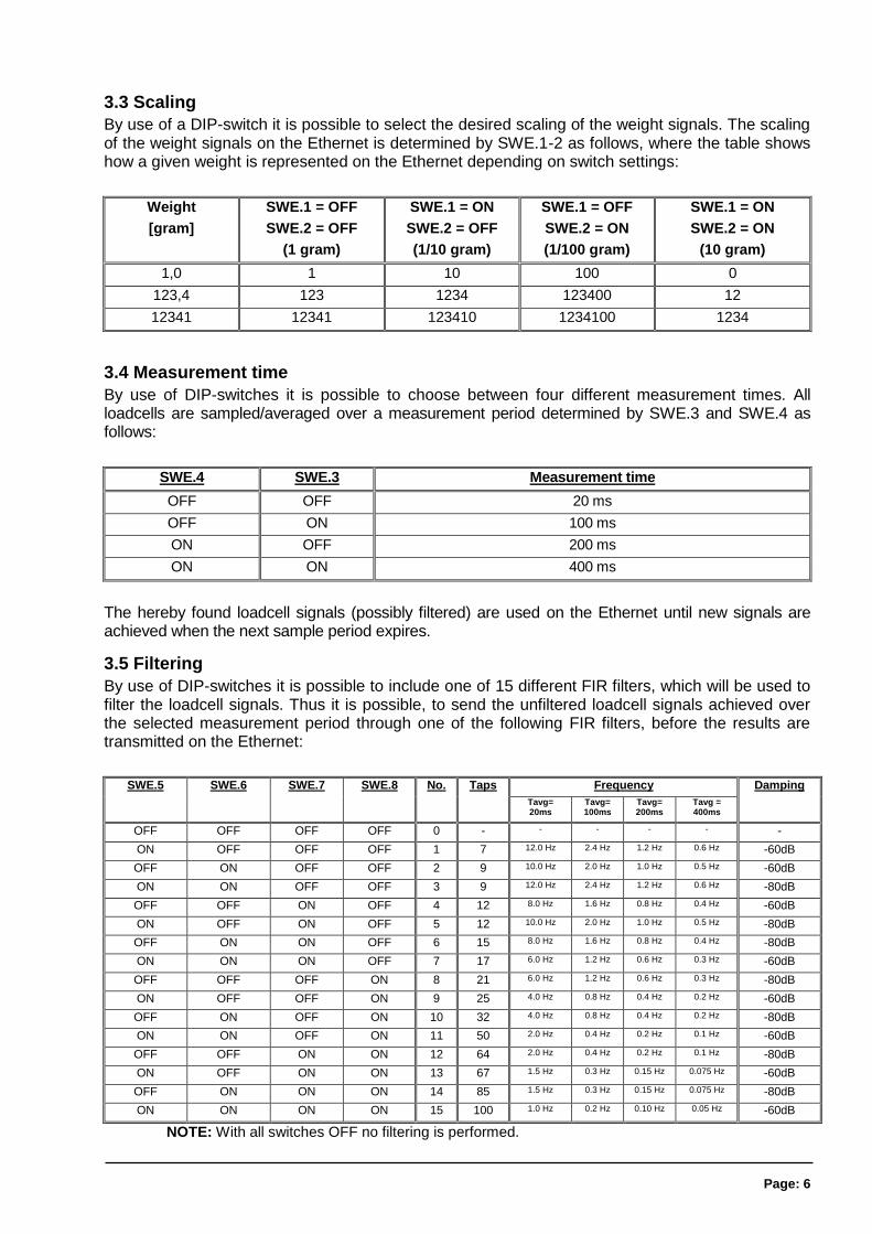
3.3 Scaling
By use of a DIP-switch it is possible to select the desired scaling of the weight signals. The scaling of the weight signals on the Ethernet is determined by SWE.1-2 as follows, where the table shows how a given weight is represented on the Ethernet depending on switch settings:
Weight
[gram]
SWE.1 = OFF
SWE.2 = OFF
(1 gram)
SWE.1 = ON
SWE.2 = OFF
(1/10 gram)
SWE.1 = OFF
SWE.2 = ON
(1/100 gram)
SWE.1 = ON
SWE.2 = ON
(10 gram)
1,0 1 10 100 0
123,4 123 1234 123400 12
12341 12341 123410 1234100 1234
3.4 Measurement time
By use of DIP-switches it is possible to choose between four different measurement times. All loadcells are sampled/averaged over a measurement period determined by SWE.3 and SWE.4 as follows:
SWE.4 SWE.3 Measurement time
OFF OFF 20 ms
OFF ON 100 ms
ON OFF 200 ms
ON ON 400 ms
The hereby found loadcell signals (possibly filtered) are used on the Ethernet until new signals are achieved when the next sample period expires.
3.5 Filtering
By use of DIP-switches it is possible to include one of 15 different FIR filters, which will be used to filter the loadcell signals. Thus it is possible, to send the unfiltered loadcell signals achieved over the selected measurement period through one of the following FIR filters, before the results are transmitted on the Ethernet:
SWE.5 SWE.6 SWE.7 SWE.8 No. Taps Frequency Damping
Tavg= 20ms
Tavg= 100ms
Tavg= 200ms
Tavg = 400ms
OFF OFF OFF OFF 0 - - - - - -
ON OFF OFF OFF 1 7 12.0 Hz 2.4 Hz 1.2 Hz 0.6 Hz -60dB
OFF ON OFF OFF 2 9 10.0 Hz 2.0 Hz 1.0 Hz 0.5 Hz -60dB
ON ON OFF OFF 3 9 12.0 Hz 2.4 Hz 1.2 Hz 0.6 Hz -80dB
OFF OFF ON OFF 4 12 8.0 Hz 1.6 Hz 0.8 Hz 0.4 Hz -60dB
ON OFF ON OFF 5 12 10.0 Hz 2.0 Hz 1.0 Hz 0.5 Hz -80dB
OFF ON ON OFF 6 15 8.0 Hz 1.6 Hz 0.8 Hz 0.4 Hz -80dB
ON ON ON OFF 7 17 6.0 Hz 1.2 Hz 0.6 Hz 0.3 Hz -60dB
OFF OFF OFF ON 8 21 6.0 Hz 1.2 Hz 0.6 Hz 0.3 Hz -80dB
ON OFF OFF ON 9 25 4.0 Hz 0.8 Hz 0.4 Hz 0.2 Hz -60dB
OFF ON OFF ON 10 32 4.0 Hz 0.8 Hz 0.4 Hz 0.2 Hz -80dB
ON ON OFF ON 11 50 2.0 Hz 0.4 Hz 0.2 Hz 0.1 Hz -60dB
OFF OFF ON ON 12 64 2.0 Hz 0.4 Hz 0.2 Hz 0.1 Hz -80dB
ON OFF ON ON 13 67 1.5 Hz 0.3 Hz 0.15 Hz 0.075 Hz -60dB
OFF ON ON ON 14 85 1.5 Hz 0.3 Hz 0.15 Hz 0.075 Hz -80dB
ON ON ON ON 15 100 1.0 Hz 0.2 Hz 0.10 Hz 0.05 Hz -60dB
NOTE: With all switches OFF no filtering is performed.
Page: 7
4) Data Processing
4.1 Zeroing, calibration and weight calculation
Calculation of system weight(s) is done by addition of the weight registers for the loadcells belong-ing to the system. This is explained below. Note that the result is only valid if all status registers for the loadcells in question indicate no errors. It should also be noted that it is up to the master to ensure the usage of consistent loadcell data when calculating the system weight (the used data should come from the same telegram).
4.1.1 Zeroing of weighing system
Zeroing of a weighing system (all loadcells in the specific system) should be performed as follows, taking into account that no loadcell errors may be present during the zeroing procedure:
1) The weighing arrangement should be empty and clean.
2) The EtherNetIP master verifies that no loadcell errors are present, after which it reads and stores the actual weight signals for the loadcells of the actual system in corresponding zeroing registers:
LcZero[x]=LcSignal[x]
3) After this the uncalibrated gross weight for loadcell X can be calculated as:
LcGross[X] = LcSignal[X] – LcZero[X]
4.1.2 Corner calibration of weighing system
In systems where the load is not always placed symmetrically the same place (for example a plat-form weight where the load can be placed randomly on the platform when a weighing is to take place), a fine calibration of a systems corners can be made, so that the weight indicates the same independent of the position of the load. This is done as follows:
1) Check that the weighing arrangement is empty. Zero the weighing system.
2) Place a known load (CalLoad) directly above the loadcell that is to be corner cali-brated.
3) Calculate the corner calibration factor that should be multiplied on the uncalibrat-ed gross weight of the loadcell in order to achieve correct showing as:
CornerCalFactor[x] = (CalLoad)/(LcGross[x])
After this the determined corner calibration factor is used to calculate the cali-brated gross weight of the loadcell as follows:
LcGrossCal[x] = CornerCalFactor[x] * LcGross[x]

Page: 8
4.1.3 Calculation of uncalibrated system weight
Based on the loadcell gross values (LcGross[x] or LcGrossCal[x]), whether they are corner calibrated or not, a uncalibrated system weight can be calculated as either:
Gross = LcGross[X1] + LcGross[X2] + …
or:
Gross = LcGrossCal[X1] + LcGrossCal[X2] + …
4.1.4 System calibration of weighing system
Based on the uncalibrated system weight a system calibration can be made as follows:
1) Check that the weighing arrangement is empty. Zero the weighing system.
2) Place a known load (CalLoad) on the weighing arrangement.
3) Calculate the calibration factor that should be multiplied on the uncalibrated sys-tem weight in order to achieve correct showing as:
CalFactor = (CalLoad)/(Actual Gross)
After this the determined calibration factor is used to calculate the calibrated system weight as fol-lows:
GrossCal = CalFactor * Gross
If the determined calibration factor falls outside the interval 0.9 to 1.1 it is very likely that there is something wrong with the mechanical part of the system. This does not however apply to systems that do not have a loadcell under each supporting point. For example on a three legged tank with only one loadcell, you should get a calibration factor of approximately 3 because of the two “dum-my” legs.

Page: 9
5) Installation of System
5.1 Checklist during installation
During installation of the system the following should be checked:
1. All hardware connections are made as described below.
2. Setup IP Address etc. with EEEthSetup as describe below.
3. If necessary the EtherNetIP master should be configured to communicate with the 4X50 Ethernet unit using the supplied EDS file.
4. Set the scaling/resolution of the weight signal by use of SWE.1 as described earli-er.
5. Set the desired measurement time by use of SWE.3-SWE.4 as described earlier.
6. Select the desired filter by use of SWE.5-SWE.8 as described earlier.
7. The loadcells are mounted mechanically and connected to BNC connectors in the front panel of the 4X50 unit.
8. The 4X50 Ethernet unit is connected to the EtherNetIP network using theRS45 Ethernet connector in the front panel.
9. Power (24VDC) is applied at the 2 pole power connectors in the front panel of the 4X50 unit as described in the hardware section, and the EtherNetIP communica-tion is started.
10. Verify that the MS lamp and the NS lamp both end up green .
11. Verify that the TxLC lamp (yellow) is lit (turns on after approx. 5 seconds).
12. Verify that the TxBB lamp (green) are lit (after 10 seconds).
13. Verify that NONE of the 1, 2, 3, 4 or D1 lamps (red) are lit.
14. Verify that the 4X50 Ethernet system unit has found the correct loadcells (LcRegis-ter), and that no loadcell errors are indicated (LcStatus(x)).
15. Verify that every loadcell gives a signal (LcSignal(x)) by placing a load directly above each loadcell one after the other (possibly with a known load).
The system is now installed and a zero and fine calibration is made as described earlier. Finally verify that the weighing system(s) returns a value corresponding to a known actual load.
Note that in the above checklist no consideration has been made on which functions are imple-mented on the EtherNetIP master.
Page: 10
6) Hardware Description
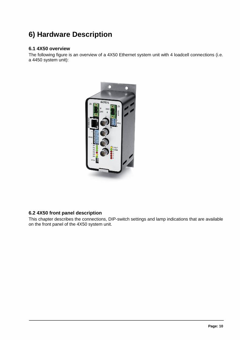
6.1 4X50 overview
The following figure is an overview of a 4X50 Ethernet system unit with 4 loadcell connections (i.e. a 4450 system unit):
6.2 4X50 front panel description
This chapter describes the connections, DIP-switch settings and lamp indications that are available on the front panel of the 4X50 system unit.
Page: 11
6.2.1 Connection of power
The 4X507 system unit is powered by applying +24VDC on the green two pole connectors (J2 and J3) as specified on the front panel of the 4X50 system unit. This powers the entire 4X50 system unit including the loadcells.
IMPORTANT: The used power supply must be stable and free of transients. It may therefore be necessary to use a separate power supply dedicated to the weighing system, and not connected to any other equipment.
NOTE: If the loadcells are to be placed inside an EX area, then the 4X50 system unit itself MUST be placed outside the EX area, and the 4X50 system unit MUST be supplied as follows:
1) The 2 pole connector (J3), located to the right above the 4 pole DIP-switch block, MUST be powered by a 4051A power supply (+24VDC ATEX approved) from Alfa Laval A/S.
2) The 2 pole connector (J2), located to the left above the RJ45 Ethernet connector, MUST be powered by a separate +24VDC, that has NO connection to the ATEX approved +24VDC from the above mentioned 4051A power supply.
6.2.2 Connection of loadcells
The loadcells must be connected to the available BNC connectors in the front panel of the 4X50 system unit. The loadcells are connected starting with the connector marked 1 and continuing on-wards in rising order. Thus if three loadcells are to be connected, they should be connected to the BNC connectors marked 1, 2 and 3.
6.2.3 Ethernet connector
The front panel of the 4X50 system unit is equipped with a standard Ethernet RJ47 connector for Cat5 cables.
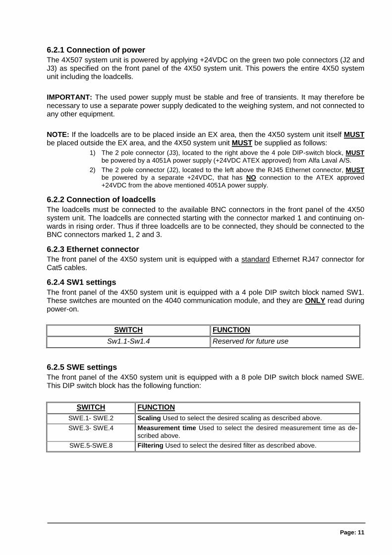
6.2.4 SW1 settings
The front panel of the 4X50 system unit is equipped with a 4 pole DIP switch block named SW1. These switches are mounted on the 4040 communication module, and they are ONLY read during power-on.
SWITCH FUNCTION
Sw1.1-Sw1.4 Reserved for future use
6.2.5 SWE settings
The front panel of the 4X50 system unit is equipped with a 8 pole DIP switch block named SWE. This DIP switch block has the following function:
SWITCH FUNCTION
SWE.1- SWE.2 Scaling Used to select the desired scaling as described above.
SWE.3- SWE.4 Measurement time Used to select the desired measurement time as de-scribed above.
SWE.5-SWE.8 Filtering Used to select the desired filter as described above.
Page: 12
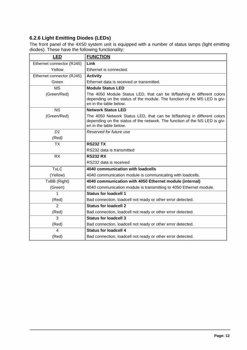
6.2.6 Light Emitting Diodes (LEDs)
The front panel of the 4X50 system unit is equipped with a number of status lamps (light emitting diodes). These have the following functionality:
LED FUNCTION
Ethernet connector (RJ45)
Yellow
Link
Ethernet is connected.
Ethernet connector (RJ45)
Green
Activity
Ethernet data is received or transmitted.
MS
(Green/Red)
Module Status LED
The 4050 Module Status LED, that can be lit/flashing in different colors depending on the status of the module. The function of the MS LED is giv-en in the table below.
NS
(Green/Red)
Network Status LED
The 4050 Network Status LED, that can be lit/flashing in different colors depending on the status of the network. The function of the NS LED is giv-en in the table below.
D1
(Red)
Reserved for future use
TX RS232 TX
RS232 data is transmitted
RX RS232 RX
RS232 data is received
TxLC
(Yellow)
4040 communication with loadcells
4040 communication module is communicating with loadcells.
TxBB (Right)
(Green)
4040 communication with 4050 Ethernet module (internal)
4040 communication module is transmitting to 4050 Ethernet module.
1
(Red)
Status for loadcell 1
Bad connection, loadcell not ready or other error detected.
2
(Red)
Status for loadcell 2
Bad connection, loadcell not ready or other error detected.
3
(Red)
Status for loadcell 3
Bad connection, loadcell not ready or other error detected.
4
(Red)
Status for loadcell 4
Bad connection, loadcell not ready or other error detected.
Page: 13
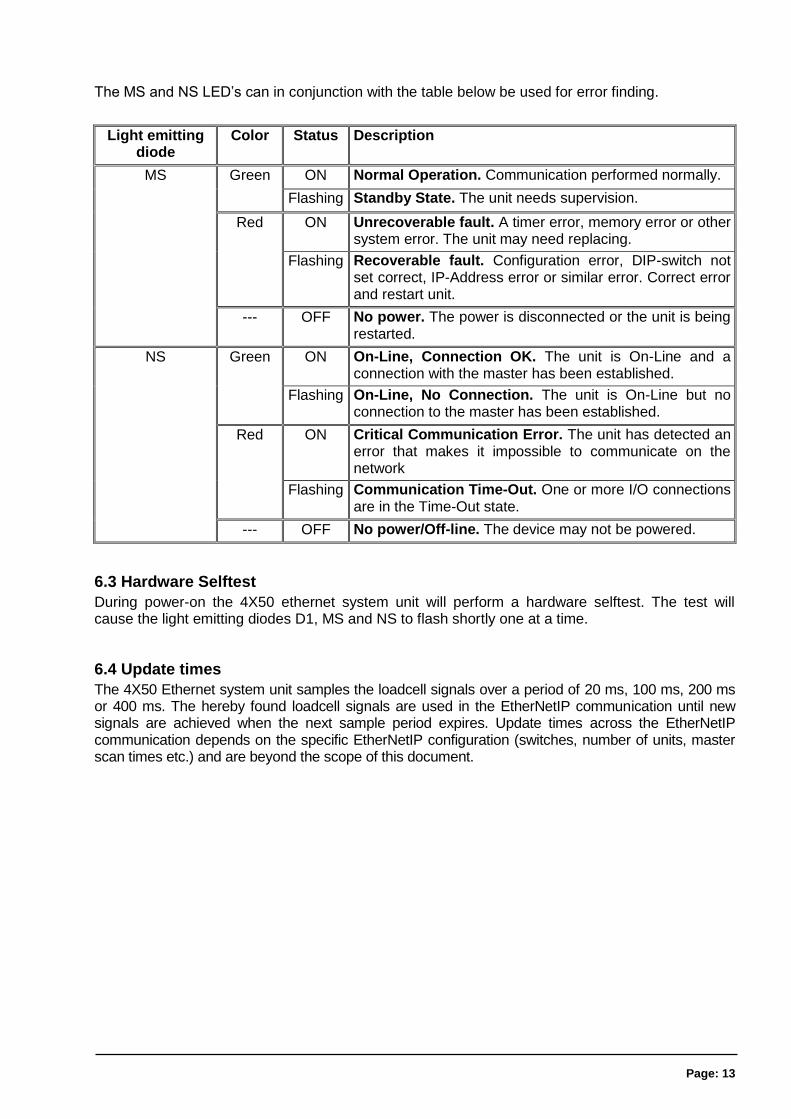
The MS and NS LED’s can in conjunction with the table below be used for error finding.
Light emitting diode
Color Status Description
MS Green ON Normal Operation. Communication performed normally.
Flashing Standby State. The unit needs supervision.
Red ON Unrecoverable fault. A timer error, memory error or other system error. The unit may need replacing.
Flashing Recoverable fault. Configuration error, DIP-switch not set correct, IP-Address error or similar error. Correct error and restart unit.
--- OFF No power. The power is disconnected or the unit is being restarted.
NS Green ON On-Line, Connection OK. The unit is On-Line and a connection with the master has been established.
Flashing On-Line, No Connection. The unit is On-Line but no connection to the master has been established.
Red ON Critical Communication Error. The unit has detected an error that makes it impossible to communicate on the network
Flashing Communication Time-Out. One or more I/O connections are in the Time-Out state.
--- OFF No power/Off-line. The device may not be powered.
6.3 Hardware Selftest
During power-on the 4X50 ethernet system unit will perform a hardware selftest. The test will cause the light emitting diodes D1, MS and NS to flash shortly one at a time.
6.4 Update times
The 4X50 Ethernet system unit samples the loadcell signals over a period of 20 ms, 100 ms, 200 ms or 400 ms. The hereby found loadcell signals are used in the EtherNetIP communication until new signals are achieved when the next sample period expires. Update times across the EtherNetIP communication depends on the specific EtherNetIP configuration (switches, number of units, master scan times etc.) and are beyond the scope of this document.
Page: 14
7) Appendices
7.1 Appendix A – Setup
The MAC address of the module is preset to a unique value within the Alfa Laval A/S range. The default settings for IP address etc. are
DHCP: Disabled
IP Address: 192.168.1.199
Subnet mask: 255.255.255.0
Gateway: 192.168.1.254
These defaults can be altered by the EEEthSetup software- please refer to the separate users guide for further details.
7.2 Appendix B – Allen Bradley connection
To connect the module to an Allen Bradley (Rockwell Automation) PLC using the Logix 5000 soft-ware the following must be observed:
1. Use the “ETHERNET MODULE Generic Ethernet Module
2. Set connection format to “SINT”
3. Set “Input” “Assembly instance to 103, “Size” 26 (8-bit)
4. Set “Output” “Assembly instance to 102, “Size” 2 (8-bit)
5. Set “Configuration” “Assembly instance to 101, “Size” 1 (8-bit)
7.3 Appendix C – Omron connection
The supplied EDS file can be used in the Omron configurator.
But please beware that the terms “input” and “output” may be confusing in the Omron configura-tor. These terms are always from the PLC’s point of view. So the data from the 4x50 module to the PLC is referred to as “input” even though it is actually an output from the 4x50.
The data from the 4x50 module is found the input assembly 103.
The output and the confirmation assemblies (101 and 102) are not used
7.4 Appendix D – Internal Features
7.4.1 4050 Ethernet module
This chapter describes possible connections, DIP-switch settings and jumper settings that are available internally on the 4050 Ethernet module. These will normally be set from Alfa Laval A/S and should only be changed in special situations.
Page: 15
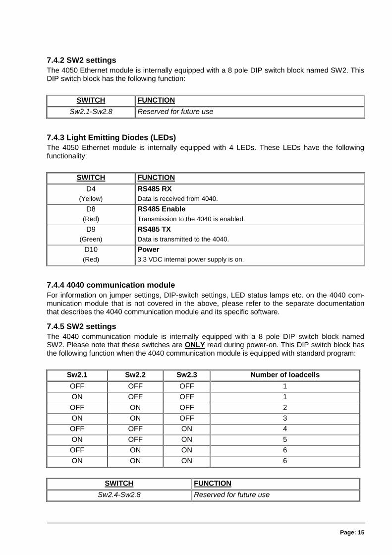
7.4.2 SW2 settings
The 4050 Ethernet module is internally equipped with a 8 pole DIP switch block named SW2. This DIP switch block has the following function:
SWITCH FUNCTION
Sw2.1-Sw2.8 Reserved for future use
7.4.3 Light Emitting Diodes (LEDs)
The 4050 Ethernet module is internally equipped with 4 LEDs. These LEDs have the following functionality:
SWITCH FUNCTION
D4
(Yellow)
RS485 RX
Data is received from 4040.
D8
(Red)
RS485 Enable
Transmission to the 4040 is enabled.
D9
(Green)
RS485 TX
Data is transmitted to the 4040.
D10
(Red)
Power
3.3 VDC internal power supply is on.
7.4.4 4040 communication module
For information on jumper settings, DIP-switch settings, LED status lamps etc. on the 4040 com-munication module that is not covered in the above, please refer to the separate documentation that describes the 4040 communication module and its specific software.
7.4.5 SW2 settings
The 4040 communication module is internally equipped with a 8 pole DIP switch block named SW2. Please note that these switches are ONLY read during power-on. This DIP switch block has the following function when the 4040 communication module is equipped with standard program:
Sw2.1 Sw2.2 Sw2.3 Number of loadcells
OFF OFF OFF 1
ON OFF OFF 1
OFF ON OFF 2
ON ON OFF 3
OFF OFF ON 4
ON OFF ON 5
OFF ON ON 6
ON ON ON 6
SWITCH FUNCTION
Sw2.4-Sw2.8 Reserved for future use
Page: 16
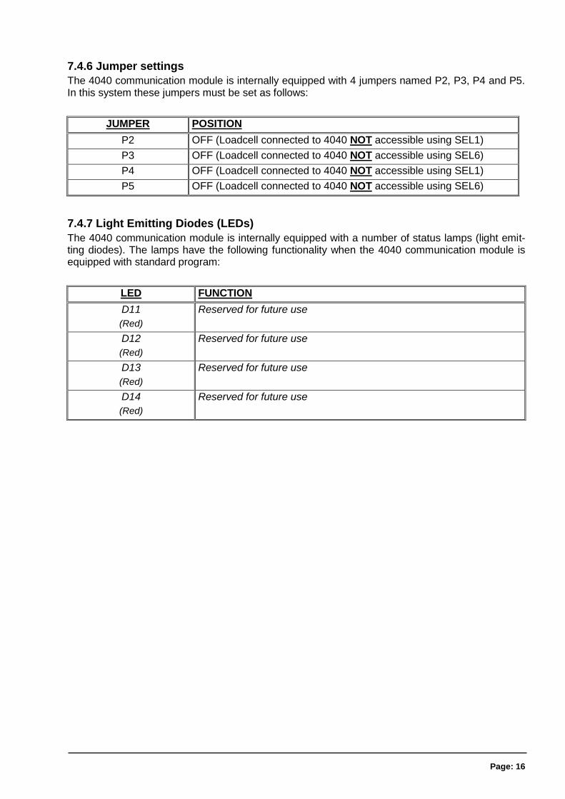
7.4.6 Jumper settings
The 4040 communication module is internally equipped with 4 jumpers named P2, P3, P4 and P5. In this system these jumpers must be set as follows:
JUMPER POSITION
P2 OFF (Loadcell connected to 4040 NOT accessible using SEL1)
P3 OFF (Loadcell connected to 4040 NOT accessible using SEL6)
P4 OFF (Loadcell connected to 4040 NOT accessible using SEL1)
P5 OFF (Loadcell connected to 4040 NOT accessible using SEL6)
7.4.7 Light Emitting Diodes (LEDs)
The 4040 communication module is internally equipped with a number of status lamps (light emit-ting diodes). The lamps have the following functionality when the 4040 communication module is equipped with standard program:
LED FUNCTION
D11
(Red)
Reserved for future use
D12
(Red)
Reserved for future use
D13
(Red)
Reserved for future use
D14
(Red)
Reserved for future use
Page: 17
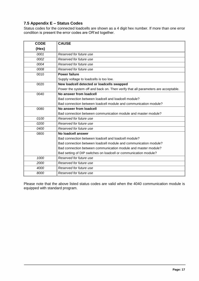
7.5 Appendix E – Status Codes
Status codes for the connected loadcells are shown as a 4 digit hex number. If more than one error condition is present the error codes are OR’ed together.
CODE
(Hex)
CAUSE
0001 Reserved for future use
0002 Reserved for future use
0004 Reserved for future use
0008 Reserved for future use
0010 Power failure
Supply voltage to loadcells is too low.
0020 New loadcell detected or loadcells swapped
Power the system off and back on. Then verify that all parameters are acceptable.
0040 No answer from loadcell
Bad connection between loadcell and loadcell module?
Bad connection between loadcell module and communication module?
0080 No answer from loadcell
Bad connection between communication module and master module?
0100 Reserved for future use
0200 Reserved for future use
0400 Reserved for future use
0800 No loadcell answer
Bad connection between loadcell and loadcell module?
Bad connection between loadcell module and communication module?
Bad connection between communication module and master module?
Bad setting of DIP switches on loadcell or communication module?
1000 Reserved for future use
2000 Reserved for future use
4000 Reserved for future use
8000 Reserved for future use
Please note that the above listed status codes are valid when the 4040 communication module is equipped with standard program.
Page: 18
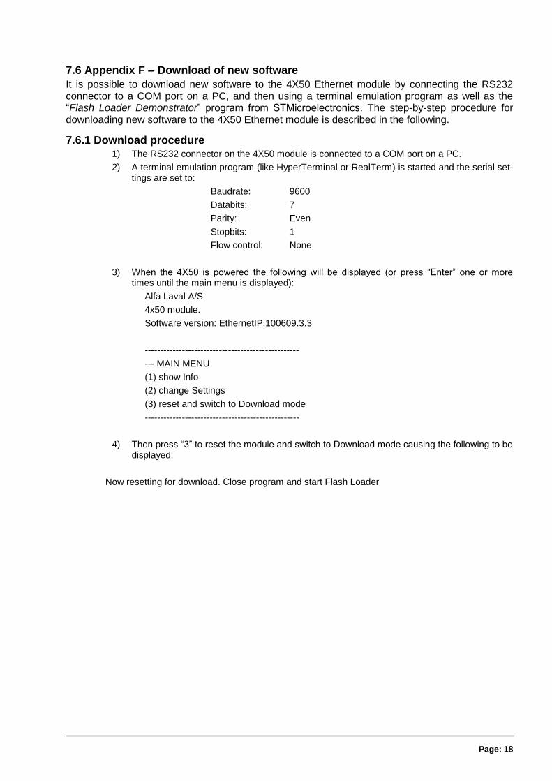
7.6 Appendix F – Download of new software
It is possible to download new software to the 4X50 Ethernet module by connecting the RS232 connector to a COM port on a PC, and then using a terminal emulation program as well as the “Flash Loader Demonstrator” program from STMicroelectronics. The step-by-step procedure for downloading new software to the 4X50 Ethernet module is described in the following.
7.6.1 Download procedure 1) The RS232 connector on the 4X50 module is connected to a COM port on a PC.
2) A terminal emulation program (like HyperTerminal or RealTerm) is started and the serial set-tings are set to:
Baudrate: 9600
Databits: 7
Parity: Even
Stopbits: 1
Flow control: None
3) When the 4X50 is powered the following will be displayed (or press “Enter” one or more times until the main menu is displayed):
Alfa Laval A/S
4x50 module.
Software version: EthernetIP.100609.3.3
--------------------------------------------------
--- MAIN MENU
(1) show Info
(2) change Settings
(3) reset and switch to Download mode
--------------------------------------------------
4) Then press “3” to reset the module and switch to Download mode causing the following to be displayed:
Now resetting for download. Close program and start Flash Loader
Page: 19
5) Without pressing any keys close down the terminal program while leaving the 4x50 module powered and connected to the PC.
6) Start the “Flash Loader Demonstrator” program from STMicroelectronics. If the program has not yet been installed on the PC, install it by running the supplied “Flash_Loader_Demonstrator_v2.2.0_Setup.exe” file and following the standard installation instructions.
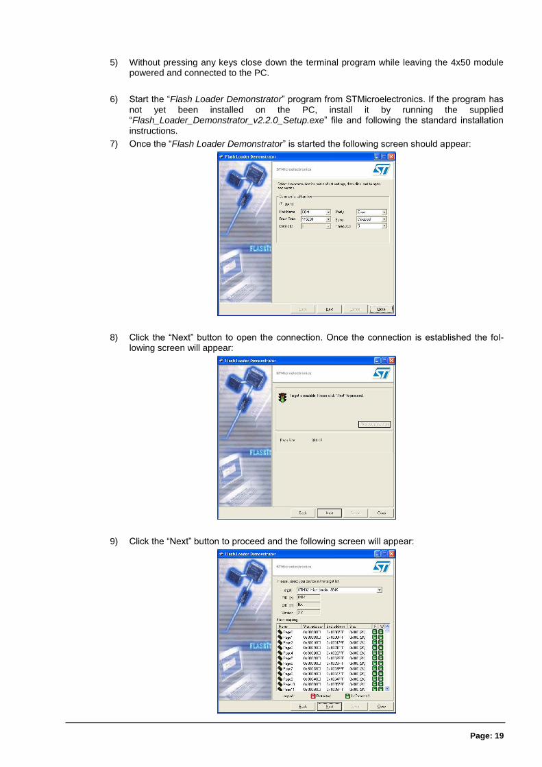
7) Once the “Flash Loader Demonstrator” is started the following screen should appear:
8) Click the “Next” button to open the connection. Once the connection is established the fol-lowing screen will appear:
9) Click the “Next” button to proceed and the following screen will appear:
Page: 20
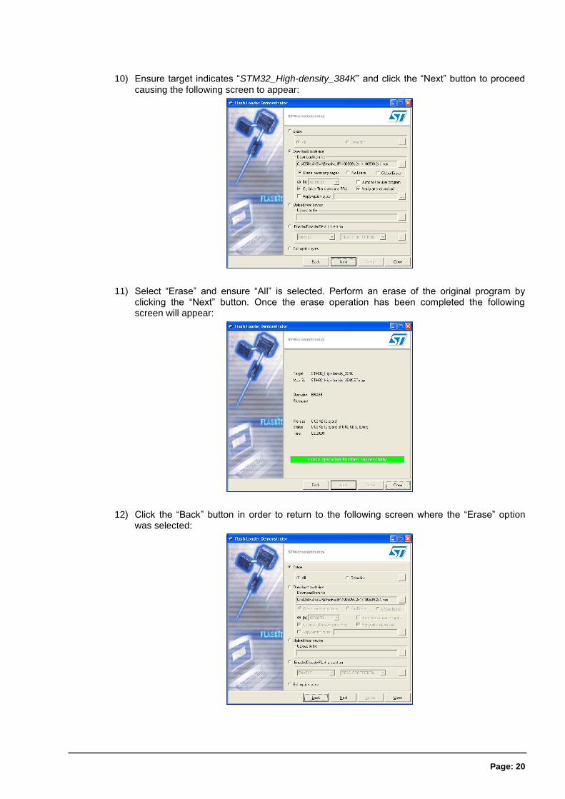
10) Ensure target indicates “STM32_High-density_384K” and click the “Next” button to proceed causing the following screen to appear:
11) Select “Erase” and ensure “All” is selected. Perform an erase of the original program by clicking the “Next” button. Once the erase operation has been completed the following screen will appear:
12) Click the “Back” button in order to return to the following screen where the “Erase” option was selected:
Page: 21
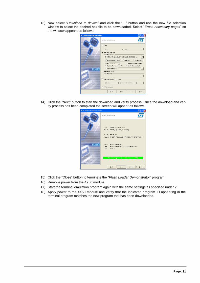
13) Now select “Download to device” and click the “…” button and use the new file selection window to select the desired hex file to be downloaded. Select “Erase necessary pages” so the window appears as follows:
14) Click the “Next” button to start the download and verify process. Once the download and ver-ify process has been completed the screen will appear as follows:
15) Click the “Close” button to terminate the “Flash Loader Demonstrator” program.
16) Remove power from the 4X50 module.
17) Start the terminal emulation program again with the same settings as specified under 2.
18) Apply power to the 4X50 module and verify that the indicated program ID appearing in the terminal program matches the new program that has been downloaded.

Page: 22
8) How to contact Alfa Laval Kolding A/S
For further information please feel free to contact: Alfa Laval Kolding A/S
31, Albuen - DK 6000 Kolding - Denmark
Registration number: 30938011
Tel switchboard: +45 79 32 22 00 - Fax switchboard: +45 79 32 25 80
www.alfalaval.com - [email protected]
Contact details for all countries are continually updated on our websites.

Page: 23
9) EC Declaration of Conformity
EC Declaration of Conformity
The designated company Alfa Laval Kolding A/S Company name
Albuen 31, 6000 Kolding, Denmark Address
+ +45 79 32 22 00 Phone no.
hereby declare that
Alfa Laval ETHERNET SYSTEM TEXXXXXXXXXXXX Denomination Type
valid for serial numbers from 2017-00001 and subsequent serial numbers.
is in conformity with the provisions of the Directive 73/23/EEC appendix IIIB and directive 89/356/EEC. And furthermore declares that the following (parts/clauses of) applicable directives have been used: - EN 61010 Part 1 (Safety requirements for electrical equipment for measurements control and laboratory use) - EN 60529 (degrees of protection provided by enclosures) - EN50081 part 1 (EMC, generic emission standard) - 50082 part 2 (EMC, generic immunity standard)
Global Product Quality Manager Pumps, Valves, Fittings and Tank Equipment Lars Kruse Andersen
Title Name Signature
August 1, 2017 Kolding Date Place


