MANUAL No.B58443 00304A INSTRUCTION MANUAL ALTERNATING CURRENT GENERATING SETS DCA-70,-125,-180ESEI 2-8-5 Nihonbashi-horidomecho, Chuo-ku, Tokyo, 103-8566 Japan IMPORTANT : READ AND UNDERSTAND THIS MANUAL CAREFULLY BEFORE USE OF THIS MACHINE. KEEP THIS MANUAL FOR YOUR FUTURE REFERENCE.
Transcript
MANUAL No.B58443 00304A
INSTRUCTION MANUAL
ALTERNATING CURRENT GENERATING SETS
DCA-70,-125,-180ESEI
2-8-5 Nihonbashi-horidomecho, Chuo-ku, Tokyo, 103-8566 Japan
IMPORTANT : READ AND UNDERSTAND THIS MANUAL
CAREFULLY BEFORE USE OF THIS MACHINE. KEEP THIS
MANUAL FOR YOUR FUTURE REFERENCE.
- 1 -
FOREWORD
We are very thankful for your special choice of our MACHINE in the market. Please read this manual carefully and understand for proper use this machine. Please keep this manual at your prescribed location where operator can always take this manual. If you have any question or problem on this operation, please contact your nearest Distributors. Pay special attention to statements preceded by the following word.
DANGER - indicates an imminently hazardous situation which, if not heeded, will result in death or serious injury.
WARNING - indicates a potentially hazardous situation which, if not heeded, could result in death or serious injury.
CAUTION - indicates a hazardous situation which, if not heeded, may result in minor or moderate injury or damage to the machine. NOTE - indicates useful information for the machine operations.
- 2 -
SAFETY PRECAUTIONS FOR GENERATORS
In order to ensure safe operation, the following symbols are used for explanation of the machine operation.
The following symbols, found throughout this manual, alert you to potentially dangerous conditions to the operator, service personnel, or the equipment.
WARNING This symbol refers to a hazard or unsafe practice which can result in severe personal injury or death.
CAUTION This symbol refers to a hazard or unsafe practice which can result in personal injury or product or property damage.
[Note] : This symbols show handling precautions for effective operation and many years of satisfactory operation.
Some of the items shown by " CAUTION " may also cause death or serious injury. Be sure to observe all the items, as they are important for safe operation.
* If the machine is used by an outsider, you are requested to explain him correct handling
and advise him to read this instruction manual carefully. * Do not modify the machine at your discretion, as it affects the safety, performance or the
life of the machine. * If the machine is modified or it is used incorrectly against this manual or unauthorized
parts are used, the warranty of manufacturer will become invalid.
- 3 -
Safety label
Safety labels are attached to the following positions of the machine. * Keep these safety labels clean at all times. * When safety labels are spoiled or lost, contact distributor or our office specifying the nameplate
No. shown below and ask for new ones.
Parts name Parts number CAUTION: Instruction manual B9111 0230
D A N G E R : Electric shock B4510 0250
WARNING: Fire/explosion B9045 0100
CAUTION: Burn B9111 0240
CAUTION: Moving parts B9040 0050
CAUTION: Emergency stop B9044 0000
CAUTION: Hot coolant/Battery B9041 0020
CAUTION: Engine fan B9040 0060
WARNING: Falling B9111 0250
WARNING: Engine exhaust B9042 0020
CAUTION Instruction manual ■ Do not use machine before reading the instruction manual. ■ Do access to machine in accordance
with the instruction manual when machine is in fault.
■ Do consult to authorized person for repair or maintenance to avoid incidents.
- 4 -
DANGER ELECTRIC SHOCK can kill. ■ Do not touch the output terminals during operation to prevent decease due to electric shock. * Never touch the output terminals during operation. If your hands or
the machine are wet, it will result in a death or serious injury. * When a wiring work is required, be sure to turn OFF the circuit breaker and stop the machine. * Keep the output terminal cover closed and the terminal bolts tightened while the machine is
running. * A low voltage is generated even when the machine is in low speed idle operation. Be sure to
stop the machine completely. ■ Do not touch the electrical parts in the machine during operation, as it may lead to death
due to electric shock. * Always close the control panel and tighten the fixing bolts before operating the machine. * Always close the side door and lock it before operating the machine. * When opening the control panel for voltage selection, etc., turn OFF the circuit breaker and stop
the machine.
DANGER ELECTRIC SHOCK by leak can kill. ■ Improper grounding may lead to death due to electric shock. * Be sure to execute the grounding of the machine and the load according
to the local rule.
CAUTION
MOVING PARTS can cause severe injury. ■ Rotary unit which runs at a high speed is located in the machine.
(Note that it is very dangerous if you touch it.) * Be sure to close the door and lock it during operation. * When the door needs to be opened during operation, do not get your
hands and head in the machine to prevent them from being caught in the machine which may lead to injury.
* When making check or maintenance of the machine, be sure to stop the machine in advance.
- 5 -
WARNING DIESEL FUEL can cause fire or explosion. ■ Fuel and oil are flammable. Incorrect handling results in danger
of ignition or fire. * When fuel needs to be supplied to the machine, be sure to stop
the engine. Refrain from smoking. Keep the machine away from fire. * Do not leave flammable objects (paper, wood chips, etc.) and hazardous objects (oil, powder,
etc.) near the machine. * Wipe off spilt fuel and oil.
CAUTION
HOT COOLANT can cause severe scalds. ■ If the radiator cap is opened while the water temperature is high,
steam or hot water will spout out. * During operation or immediately after stopping the machine, do not open
the radiator cap while the water temperature is high. * When cooling water needs to be checked or supplied, wait until the engine is cooled (50℃ or
less as measured with the water temperature gauge).
CAUTION HOT PARTS can burn skin. ■ High temperature units are located in the machine. (Note that these units are very dangerous if they are used incorrectly.) * Be sure to close the door and lock it during operation. * If the door needs to be opened during operation, do not get your hands
and head in the machine to prevent unexpected burns. * When making check or maintenance of the machine, be sure to stop the machine. * The bonnet is still hot even after the machine is stopped. Be careful until the engine is
completely cooled.
- 6 -
CAUTION Battery ■ Battery generates flammable gases. Improper handling may lead to
explosion or serious injury. * Battery should be charged in a well ventilated location. Otherwise,
flammable gases are accumulated which may be ignited and exploded. * When connecting a booster cable, do not jumper the terminals (+ and -). Otherwise, the
flammable gases generated from the battery may be ignited and exploded by sparks. * For maintenance of the machine, disconnect the ground cable on the ground side. ■ The battery acid is dilute sulfuric acid. Improper handling will cause unexpected burns. * When the battery acid gets on your clothes or skin, wash it out with a large volume of water
immediately. If it gets in your eyes, wash with a large volume of water immediately and consult your doctor.
- In the worst case, it will put out your eyes. ■ For checking or handling of the battery, be sure to stop the engine and turn OFF the battery
switch in advance.
WARNING ENGINE EXHAUST can kill. ■ Insufficient ventilation may lead to death due to lack of oxygen or
poisoning by exhaust gases. * Do not use the machine in a place of poor ventilation or in a place where
exhaust gases stays. * Do not use the machine indoors or in storehouse, tunnel, ship hold, tank, etc. of poor ventilation.* If it becomes necessary to use the machine in the above places, the exhaust pipe should be
extended to a well ventilated place. In this case, use a ventilator to ensure proper ventilation. * Do not direct the exhaust outlet to nearby pedestrians and houses.
CAUTION
Operator ■ Do not operate the machine if operator is tired too much or drinks some alcohol or take
some drugs. * Otherwise, it may cause unexpected accidents or injury. ■ During checking or maintenance, be sure to put on suitable clothes and protectors. * Do not put on baggy clothes, necklace, etc., because they are easily caught by projections which
may cause injuries.
CAUTION Noise ■ This machine generates large noise if the door is open. Surrounding to
large noise may cause hearing trouble. * Close and lock the door during operation. * If opening the door is necessary during operation, be sure to put on the ear protector.
- 7 -
CAUTION Connection to house wiring ■ Before connecting this machine to any building's electrical system, a licensed electrician must
install an isolation(transfer) switch. * Serious injury or death may result without this transfer switch.
CAUTION
Transportation ■ Do not lift the machine at the support hook or the ladder because it is not strong enough for
lifting and may cause a falling accident. * When lifting the machine, use the hanger located at the roof center. * Keep out under the lifted machine. ■ Do not lift or do not transport the machine during operation, as it may cause damage to the fan
or serious trouble. * When loading the machine on the truck or the like, fix the machine firmly by support hooks on
the both side. SAFETY LABEL/SICHERHEITSANHAGE
1 D A N G E R : Electric shock
2 WARNING: Fire/explosion 3 CAUTION: Burn
4 CAUTION: Moving parts 5 CAUTION: Instruction manual
6 CAUTION: Emergency stop 7 CAUTION: Hot coolant/Battery8 CAUTION: Engine fan 9 WARNING: Falling 10 WARNING: Engine exhaust
- 8 -
This instruction manual describes how to handle the machine with a view to promising safety run, maximum efficiency and long durability. Read the manual attentively before starting the machine operation for correct handling, operation and appropriate maintenance from the beginning. The maintenance schedule consists of a procedure of keeping the machine in good condition. For the user, keep the manual carefully for machine operation and maintenance according to the instructions. Observe all the safety precautions including ones stated in the manual. Entrust the repair to trained personnel of Denyo or its distributor who are capable of contacting us as required. When consulting us, specify the model and serial number indicated on the nameplate. For data not specified in the manual, see “Principal data”. The company reserves the right to make changes without prior notice.
- 9 -
Contents
SAFETY PRECAUTIONS FOR GENERATORS ------------------------------------------------------------------------ 2
1. DCA series -------------------------------------------------------------------------------------------- 11
1-1 General ------------------------------------------------------------------------------------------------- 11
3-1 Safety precautions for operation ------------------------------------------------------------------ 33
3-2 Connecting the load --------------------------------------------------------------------------------- 35
3-2-1 Precautions in connecting the load ----------------------------------------------------- 35 3-2-2 Non-liner and sensitive loads ------------------------------------------------------------ 36 3-2-3 Quality, minimum section and maximum length of cables ----------------------- 36 3-2-4 Connecting the load ------------------------------------------------------------------------ 38
- 10 -
3-3 Before starting ----------------------------------------------------------------------------------------- 40 3-3-1 Checkup before start-up ------------------------------------------------------------------- 40 3-3-2 Instruction for Fuel Source Changeover Device(Three- Way valve) ------------ 42
7-5 General specifications ----------------------------------------------------------------------- 63
7-6 Conversion list of SI units into UK/US units ----------------------------------------- 64
- 11 -
Safety precaution The user must carry out all safety precautions stated in the manual. If any statement in this book, especially with regard to safety, does not comply with local legislation, the stricter of the two shall apply.
1. DCA Series 1-1 General DCA series generator is intended for generating power source where there is no power source. For further details, see “7 Principal data”. 1-2 Machine structure The generator which is directly driven by Isuzu water-cooled diesel engine is mounted on
the common frame along with control equipment, radiator, battery, fuel tank and other auxiliary equipment. The altogether is covered by a sound-insulated steel bodywork. See Fig. 1.
1-3 Machine appearance and internal component devices 〇 There are the hanger at the center on the top surface and rope hanger on its both sides. When lifting the machine, use the hanger. Do not resort to winding rope because it is not
strong enough. See Fig. 2. 〇 The engine cooling water refilling port and fuel refilling port are located on the top
surface of the machine. 〇 The drain plugs for engine oil, cooling water and fuel are located at the base side under
the machine. Tags of their respective names are attached there.
- 12 -
Model DCA-125ESEI
Fig.1
1. AC generator 2. Diesel engine 3. Control box 4. Fuel tank
5. Radiator 6. Battery 7. Muffler 8. Intercooler
- 13 -
Model DCA-125ESEI
Fig. 2
1. Hanger 2. Rope hanger 3. Radiator cooling water refilling port cover 4. Fuel tank refilling port cover 5. Fuel drain plug 6. Oil drain plug 7. Intercooler drain plug 8. Three phase output receptacle 9. Single phase output receptacle
10. Engine exhaust port 11. Cooling air intake port 12. Cooling air exhaust port 13. Side door 14. Drain plug engine cooling water 15. Environmental base drain 16. Three-way valve 17. Emergency stop button 18. PE earthing terminal
- 14 -
1-4 Control switches and meters 〇 The control switches and meters are located inside the door having a window on the rear
of the machine. 〇 The control panel is mounted on the bodywork with hinges and is fastened by screws. Loosening the screws has access to repairing or replacing electrical parts in the control box. 1-4-1 Engine start/stop controls
Fig.3
1. Frequency meter 2. AC ammeter 3. Ammeter change over switch 4. AC voltmeter 5. Voltage regulator 6. Circuit breaker(for main) 7. Earth leakage relay
1. Starter switch The switch is 3-position switch which can be operated with its specific key only. 1) OFF This switch should be set in this position unless the machine is in operation.
The key can be inserted or pulled out in this position. 2) RUN This switch should be set in this position when the machine is in operation. In this position, the preheating system is energized. When the preheat indicator
lamp lights up, reaching the set temperature, it goes off. Then, turn the key to “START”.
3) START
This is the position to start the engine. When your hand is released from the key after starting, it is automatically set in the position of “RUN”.
2. Emergency stop button The stop button is a push button to stop the engine in case of an emergency.
When the button is pressed, it must be unlocked by turning it anti-clockwise before the engine can be re-started.
- 16 -
1-4-2 Engine indicators 3. Engine monitor
Fig.4 (1) Engine indicator That indicates the numerical values of engine speed, engine oil pressure, run hours, battery charging voltage, or engine coolant temperature.
Indicated Items Unit
engine speed min-1 engine oil pressure ×100kPa battery charging voltage V engine coolant temperature ℃
- 17 -
- 1 - Engine Speed
Revolutions per minute is indicated. 1500min-1 is indicated at 50Hz. - 2 - Engine Oil Pressure
3.9 to 6.9 × 100 kPa should be indicated at normal engine operation. Higher value would be indicated in cold condition immediately after engine starts. Conduct a warning - up operation until it indicates normal value. - 3 - Battery Charging Voltage
That should indicate more than 12.5V at engine running. - 4 - Engine Coolant Temperature
That should indicate a temperature between 75 to 95 ℃ at engine running.
Note ; If that would indicate higher temperature, disconnect all loads, decrease the speed for cool - down operation, and wait until the temperature comes down to normal value. (2) Fuel Level Indicator That Indicates a fuel level in the fuel tank. All the lights are indicated green when the fuel is full. The green lights stop indicating one by one as the fuel level decrease, finally the red light will be indicated when it is only one green light is left. Replenish the tank when there becomes only one lamp turned on. The table below shows the relation between numbers of turn - on lamps and fuel level.
9 130 to full 210 to full 255 to full 8 120 to 130 200 to 210 240 to 255 7 115 to 120 185 to 200 225 to 240 6 105 to 115 175 to 185 210 to 225 5 95 to 105 160 to 175 195 to 210 4 90 to 95 150 to 160 180 to 195 3 75 to 90 125 to 150 150 to 180 2 60 to 75 95 to 125 115 to 150 1 0 to 60 0 to 95 0 to 115
- 18 -
(3) Alarm and Memory at Abnormal Condition When any abnormal condition occurs in engine oil pressure, battery charging voltage, or engine coolant temperature, the indication will change as the following ;
- 1 - The Indicator shows its defect with blinking numbers.
- 2 - When the abnormal condition is corrected, the on - and - off indication will stop.
- 3- If engine would stop urgently and automatically or stop manually with the abnormal condition, the abnormal value will be memorized, and then indicated even after engine is started again. In this case, keep on pushing the button “RESET” for more than 5 seconds, and the abnormal indication will be reset to normal. (4) Hour Meter ① When you turn the starter switch to “RUN” position, and push the selector button
located on the right side of the Hour Meter, you can see the numbers mentioned below ; ・ “ODD” Total running hour ・ “TRIP A ” Running hours “A” on a certain period ・ “TRIP B ” Running hours “B” on a certain period
② If you want to reset the Trip Meters, push the selector button for more than 1 second, after selecting each meters.
- 19 -
4. Indication/alarm lamp
(1) Preheat lamp This machine has automatically preheating device. If turn the starter switch to “RUN” position, it will according to cooling water (coolant) temperature with the preheat lamp goes on.When the preheat lamp goes off, it indicates that preheating is completed.
(2) Warning Lamps This monitor indicates the following failures, if any one of them occurs. ① High jacket water temperature (WATER TEMP)
This lamp goes on when the water temperature rises abnormally. If the lamp goes on during operation, the emergency stop device immediately operates to shut down the engine automatically. ② Oil pressure failure (OIL PRESS)
If this lamp goes on during operation, the emergency stop device immediately operates to shut down the engine automatically. ③ Air filter blinding (AIR FILTER)
When the air element is blinded, this lamp goes on. Indicating that the element should be immediately cleaned or replaced. ④ Over speed of engine (OVER SPEED)
This lamp goes on when the engine speed rises abnormally. If the lamp goes on during operation, the emergency stop device immediately operates to shut down the engine automatically.
- 20 -
5. Electronic Governor Controller (in the control box)
Trouble diagnostic functions
The engine controller with this unit diagnoses problems that arise with the engine control system and the engine itself. When diagnostic lamp is turned on, there are any failure in the engine control system. Refer to the engine instruction manual.
1. Normally, diagnostic lamp will be lit brightly then the lamp will be turns off,
when the starter switch is placed in the “RUN” position.
2. If engine trouble occurs, diagnostic lamp will become brightly lit as long as the starter switch remains in the “RUN” position.
- 21 -
1-4-3 Generator controls and indicators 6. Frequency meter This meter indicates the frequency of the outputted voltage. Make sure that it reads 50Hz when running.
7. Ammeter
This meter indicates the current going to the connected load. It must not exceed the rated current. 8. Voltmeter
The voltmeter indicates the outputted line voltage.
9. Three-phase circuit breaker The circuit breaker is a safety device interrupting the mains when an overload, a short
circuit or a leakage occurs at the load side connected to the receptacles. It also serves as a main switch for supplying energy from the generator to the load connected to the output receptacles.
Do not use this circuit breaker to turn on or off the load. When tripped, the breaker must be reset manually by switching it to OFF and then to ON after eliminating the cause of the trouble. 10. Earth leakage relay
DANGER :Electric shock by leakage. Be sure to connect the machine to earth. If not connected to earth, the earth leakage relay would not work. Be sure to connect the load also to earth. This relay detects a leakage and trips the mains of the three-phase circuit breaker. The earth leakage relay sensitivity is 30mA. At this time, the red lamp lights indicating a leakage occurrence. Eliminate the cause of the leakage, press the reset button, turn the tripped circuit breaker manually to OFF and then to ON.
- 22 -
11. Ammeter change over switch The switch allows measuring the outgoing current between each of the phases and also switching the meter off. 12. Voltage regulator knob The output voltage is controlled by a regulator with rotating knob. Turning clockwise increases the voltage and vice versa. 1-5 Noise
CAUTION :Injury of ears In room or environment where the sound pressure level reaches or exceeds 90dB(A), use ear protectors. The maximum sound pressure of the machine is the value specified in EN 31201. 〇 Model DCA-70……..…. dB(A) 〇 Model DCA-125………. dB(A)
〇 Model DCA-180………. dB(A)
- 23 -
2. Transportation, storage and installation 2-1 Safety precautions for transportation, storage and installation
WARNING ・ When lifting or transporting the machine, use only appropriate devices which comply with the local safety codes and regulations. ・ When lifting the machine, use the hanger located at the roof center. Do not resort to rope winding because it is not strong enough. ・ Before lifting, close and fix the doors, covers and other moving parts and clear away the machine interior and top. ・ Do not slip under a lifted machine. ・ The electrical connections shall comply with the local codes. ・ Earth the machine properly. ・ The engine exhaust gas is lethal and toxic. Do not operate in tunnel, indoors or others where the aeration is poor. If it is absolutely obliged to operate in such a place, discharge the exhaust sufficiently by a ventilating system. Never direct the engine exhaust towards passers-by. ・ Do not operate the machine in an atmosphere containing toxic or combustible gas. Otherwise, fire or explosion might occur in the machine. (Example: Near volatilizing paint solvent.) ・ Fuel and oil are combustible and undiluted anti-freeze solution is inflammable. Do not smoke while handling or refilling them. Do not get fire or heated objects near them. Do not spill or leave fuel, oil, anti-freeze solution or cleansing agent in or around the machine. If spilled, be sure to wipe off properly. ・ If necessary, provide a spark arrestor to trap incendiary exhaust sparks.
- 24 -
CAUTION ・ Install the machine on a well ventilated, horizontal, flat, dry and solid floor. If the floor is not horizontal enough to keep the machine leveled, consult your sales distributor. When installing the machine on a trailer, fasten the trailer and fix the wheels by stoppers. ・ Do not remove or unduly modify safety devices, guards, covers or insulating materials from the machine. ・ When servicing batteries, always wear protecting clothing and glasses. The battery electrolyte is a diluted sulphuric acid which can cause severe burns. Get it away from eye, skin and clothing. ・ When charging batteries, an explosive gas forms above the cells and escapes through the vents. Do not smoke near batteries just after having been charged. Never make or break live circuits or battery terminals, because a spark usually occurs. ・ Before checking the machine, stop the engine and wait for at least 10 minutes so that it will cool down completely. If done while running or immediately after shutdown, you might get burnt or injured. 2-2 Transportation 〇 When lifting or transporting the machine, use only appropriate devices which comply with the local safety codes and regulations. For dimensions and weight of the machine, refer to “ 7 Principal Data”. See Fig 5 for the center of gravity.
- 25 -
Fig. 5
〇 When lifting the machine, use the hanger located at the roof center. Never use the rope hanger because it is not strong enough to lift. 〇 Before lifting, close and fix the doors, covers, and other moving parts and clear away the machine interior and top. 〇 Do not slip under a lifted machine. 〇 Before transporting by truck or others, wind ropes on the machine to fasten it securely. 〇 Put covers so as to protect the machine from rain or moisture when transporting. 2-3 Storage 2-3-1 Storage method
1. Store the generator in a sufficiently ventilated, dry room which is free from frost, salt and dust.
Storage environment: Atmospheric temperature -5 to 40℃, humidity 85% or lower, altitude 1000m or lower. 2. Run the engine once a week until warm.
Model L W H
DCA-70ESEI 1350 500 710
DCA-125ESEI 1790 570 770
DCA-180ESEI 2050 600 780
- 26 -
3. If it is impossible to run the engine regularly, extra precautions must be taken. 1) Consult the instruction manual for the engine. 2) Remove the battery. Store it in the same environment as for the machine. Keep the battery clean and coat its terminals lightly with petroleum jelly. Recharge the battery regularly. 3) If the electrolyte has dropped to the specified level, refill it. 4) Clean the generator. Oil or fuel spillage is not allowed. Protect all electrical components against penetration by moisture. 5) Place silica gel bags, VCI paper (volatile corrosion inhibitor) or another drying agent inside the generator and close the doors. 6) Close all openings on the bodywork by sticking sheets of VCI paper with adhesive tape. 7) Enclose the generator, except the bottom, with a plastic bag. 2-3-2 Preparing for operation Before operating again the generator kept unused for a long time, remove the plastic bag, VCI paper from the openings and silica gel from inside and check the generator thoroughly. Further maintain the following items. 1. Consult the instruction manual for the engine. 2. Measure the insulation resistance of the generator with a 500-V insulation resistance tester.
The resistance must exceed 1 megohm. In case of measuring with an insulation resistance tester over 500VDC current, disconnect all connectors from the AVR located in the control box before measuring.
3. Replace the fuel filter cartridge and fill the fuel tank.
Vent the fuel system. 4. Reinstall and connect the battery. If necessary, recharge it. 5. Check the fan belt condition and tension; adjust if required. 6. Check and, if required, refill cooling water and oil. 7. Submit the generator to a test run.
- 27 -
2-4 Installation 2-4-1 Installation 1. Install the generator on a well ventilated, horizontal, even and solid floor. If the floor is not horizontal enough to keep the machine leveled, consult your sales distributor. When installing the machine on a trailer, fasten the trailer and fix the wheels by stoppers. Avoid a site exposed to rain or high temperature. The operating ambient conditions are atmospheric temperature of -5 to 40℃, humidity of 85% or lower and altitude of 1000m or lower. If the machine do not conform with the above conditions, consult your sales distributor. 2. Avoid a dusty site. If it is inevitable, provide protective devices. 3. Do not operate the machine in an atmosphere containing toxic or combustible gas.
Otherwise fire or explosion might occur in the machine. (Example:Near volatilizing paint solvent.) 4. Leave space for operation, inspection and maintenance; at least 500mm each on machine front and 1000mm each on rear and sides. See Fig. 6.
Fig. 6 Note: If the machine is operated in a smaller space than that shown above, the room
temperature will rise. Please reduce the generator output in such condition. Therefore proper power reduction is necessary.
- 28 -
If the space required above the machine is not uniform when it is operated indoors, make a decision so that: 〇 The radiator can be refilled with cooling water. 〇 The exhaust pipe can be introduced. 〇 The exhaust can smoothly be discharged.
5. Do not direct the exhaust towards passers-by or residences, etc. 6. If the generator is operated indoors; 〇 Install an exhaust pipe of sufficient diameter to let the engine exhaust gas out directly. 〇 Check for sufficient ventilation and position the ventilator so that the exhaust from the machine will not be re-circulated in the room even if the ventilation is proper. 7. Check that the inner earthing system is in compliance with the local regulations. 8. Earthing the machine 〇 If the machine is earthed in a way different from below, follow the local rule. 〇 The machine is TN system which must conform to IEC 364-3 and must directly be earthed at one neutral point. ① Be sure to connect to earth the earthing bar connected to the PE earthing terminal. ② Avoid earthing at the following places 1. Near underground utilities such as gas pipe, city water pipe, electric wires, underground cables. 2. Within 2m from lightening arrester earthing place. 3. Do not use the high voltage circuit earth commonly earthing the machine. ③ Precautions in earthing 1. Drive the earthing lugs as near the machine as possible in shady and humid soil so that its top end will sufficiently be buried inside.
2. Be sure to connect the lead-wise securely if the hanger is buried in a place of heavy traffic.
9. Also connect the load bodyworks to ground.
- 29 -
Model DCA-70ESEI
Model DCA-125ESEI
Fig. 7
1. Oil level gauge 2. Oil refilling port cap 3. Oil filter cartridge 4. Reserve tank cooling water 5. Fan belt
6. Alternator 7. Fuel filter cartridge 8. Air cleaner 9. Water separator
- 30 -
2-4-2 Checking after installation
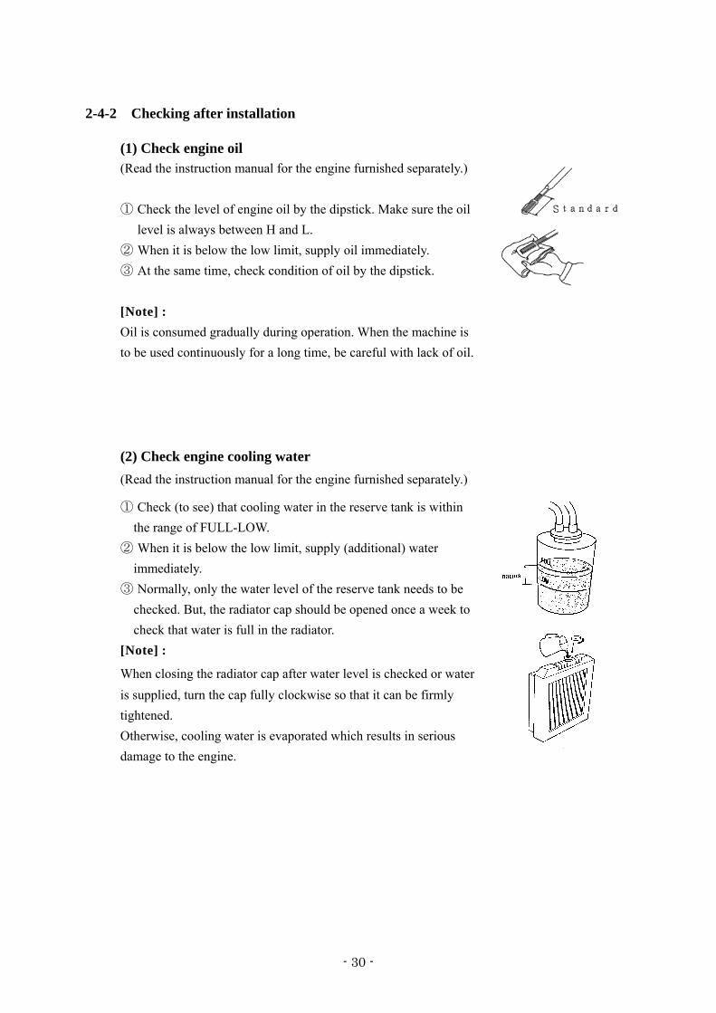
(1) Check engine oil (Read the instruction manual for the engine furnished separately.) ① Check the level of engine oil by the dipstick. Make sure the oil
level is always between H and L. ② When it is below the low limit, supply oil immediately. ③ At the same time, check condition of oil by the dipstick. [Note] : Oil is consumed gradually during operation. When the machine is to be used continuously for a long time, be careful with lack of oil.
(2) Check engine cooling water (Read the instruction manual for the engine furnished separately.)
① Check (to see) that cooling water in the reserve tank is within the range of FULL-LOW.
② When it is below the low limit, supply (additional) water immediately.
③ Normally, only the water level of the reserve tank needs to be checked. But, the radiator cap should be opened once a week to check that water is full in the radiator.
[Note] :
When closing the radiator cap after water level is checked or water is supplied, turn the cap fully clockwise so that it can be firmly tightened. Otherwise, cooling water is evaporated which results in serious damage to the engine.
- 31 -
(3) Check fan belt (Read the instruction manual for the engine furnished separately.) ① Check the belt for tension and elongation. Also, check it for
damage. Replace if necessary. ② For adjustment or replacement of the belt, refer to the
instruction manual for the engine. Press (about 6kg) the position shown by arrow mark (middle of belt) with your thumb. The bend should be within the range of 10 ㎜. Parts number of fan belt:
Model name Parts number Parts number of manufacture
DCA-180ESEI 06020 15257 113671-5160 (4) Check fuel level ① Be sure to check the quantity of fuel prior to operation to
prevent lack of fuel during operation. ② Loosen the drain plug of the fuel tank from time to time, and
remove sediment's and water at the bottom of the tank.
(5) Check battery acid level
CAUTION Battery
■ The battery acid is dilute sulfuric acid. Improper handling will cause unexpected burns. * When the battery acid gets on your clothes or skin, wash it out with a large volume of water immediately. If it gets in your eyes, wash with a large volume of water immediately and consult your doctor. - In the worst case, it will put out your eyes.
Remove the battery acid plug(cap) and check the liquid level (10-12 ㎜ above the electrodes). Supply distilled water if necessary.
- 32 -
(6) Check for leak of water and oil Check the machine for the trace of leak of oil or water. If a leak is found, check the location of leak and stop it. When the leak cannot be stopped, contact our service factory. (7) Check for loose parts Check for loose bolts and nuts. Loose parts should be tightened firmly. Particularly, make check on (the fitting of air cleaner, muffler, turbo-charger, etc.), disconnection of electric wiring, short-circuit and loose terminals. (8) Removal of foreign objects in machine * Check that tools and cleaning cloth are not left in the machine. Remove if necessary. * Check the surroundings of the muffler and engine for presence of dust and flammable
objects. Remove if necessary. * Check that the cooling air inlet and the cooling air outlet of the machine are not clogged with dust or other objects. Remove if necessary.
- 33 -
3. Operation 3-1 Safety precautions for operation DANGER
・ When the machine is running, never touch output terminals, internal wiring or other electrical parts. ・ Do not use the machine in a humid place. An excessive humidity is very dangerous. Never touch the machine if the machine or your body is wet. ・ Never fail to perform a test running for the earth leakage relay prior to operation. ・ The electrical connections shall comply with the local regulations. ・ Use cables which are not damaged. Make sure that all electrical connections are securely fastened. Damaged cables or loose connections might cause electric shocks. WARNING
・ The engine exhaust gas is lethal and toxic. Do not operate in tunnel, indoors or others where the aeration is poor. If it is absolutely obliged to operate in such a place, discharge the exhaust by a ventilation facility. Do not direct the engine exhaust towards passers-by, residences, etc. ・ Do not operate the machine in an atmosphere containing toxic or combustible gas. Otherwise, fire or explosion might occur in the machine.
(Example: Near volatilizing paint solvent.) ・ Do not refill fuel or oil while the machine is running but after stopping the engine. ・ Fuel and oil are combustible and undiluted anti-freeze solution is inflammable. Do not smoke while handling or refilling them. Do not get fire or heated object near them. ・ Do not spill or leave fuel, oil, anti-freeze solution or cleansing agent in or around the machine. ・ Never remove the cover of the output terminals during operation. Before connecting or disconnecting the cables, switch off the load and machine circuit breakers, stop the machine and make sure that the machine cannot be started inadvertently.
- 34 -
CAUTION ・ Avoid overloading the generator. The generator is provided with circuit breakers for overload protection. When a circuit breaker has tripped, reduce the concerned load before re-starting. ・ Do not connect the output voltage from the machine to facilities wired to the commercial power supply. ・ Before connecting a load, turn off a corresponding circuit breaker and make sure that the frequency, voltage and power factor of the load to connect match the generator ratings. ・ Before checking the machine, stop the engine and wait for at least 10 minutes so that it will cool down completely. If done while running or immediately after shutdown, you might get burnt or injured. ・ Do not operate the machine beyond the range given in the main specification table. ・ In room or environment where the sound pressure level reaches or exceeds 90 dB (A), use ear protectors. ・ During the operation, keep all doors closed. ・ Periodically check that: 1. All guards are in place and securely fastened. 2. All hoses and/or pipes inside the machine are in good condition, not bent and not rubbing. 3. There are no leaks of fuel, oil, cooling water, etc. 4. All fasteners are tight. 5. All electrical leads are secure and in good order. 6. The electrical cables are not damaged. NOTES ・ Do not remove any of, or tamper with, the sound-damping material. ・ Whenever an abnormal condition arises, e.g., excessive vibration, noise, odour, etc., switch the circuit breakers to OFF and stop the engine. Correct the faulty condition before re-starting.
- 35 -
3-2 Connecting the load 3-2-1 Precautions in connecting the load 〇 The switchgear, switching equipment, load and generator in the plant must be connected in compliance with local codes of low voltage power installation (1000 or less). 〇 Before starting or before connecting a new load, make sure that the generator is earthed. Use the earthing rod or, if effective, use an existing earthing installation. Any protective devices against electric shock and leakage would be useless if earthing is poor. 〇 Avoid overloading the generator. The generator is provided with circuit breakers for overload protection when a breaker has tripped, reduce the concerned load before restarting. 〇 Never connect the generator output voltage to an installation which is also connected to a commercial power supply. 〇 Before connecting a load, turn off the corresponding circuit breaker, and check whether frequency, voltage and power factor comply with the ratings of the generator. 〇 Distribution board If the outlets provided on the machine are insufficient, provide an auxiliary switchgear and connect it with the output terminals. The distribution board must comply with the local rule of power installation. 〇 Be sure to provide a load ON/OFF switch between the power outlets and load. Do not use the generator circuit breaker to turn on/off the load. 〇 Before connecting the load, stop the engine and turn off the generator circuit breaker. 〇 The load connecting cable must not get in contact with other output terminals on the terminal board.
- 36 -
3-2-2 Non-linear and sensitive loads Non-linear loads draw currents with high contents in harmonics causing distortion in the wave form of the voltage generated by the synchronous generator. In general, non-linear type loads generate a high frequency current which adversely affects the performance of inverters used to feed power voltage to variable speed motors or loads such as thyristor/rectifier controlled UPS. Loads most sensitive to voltage distortion include incandescent lamps, discharge lamps, computers, X-ray equipment, audio amplifiers and elevators. Consult your sales distributors for measures against the adverse influence of non-linear and sensitive loads. 3-2-3 Quality, minimum section and maximum length of cables 〇 The cable connected to the output terminals of the generator must be selected in accordance with local regulations. The type of cable must be determined by its rated voltage and current, current carrying capacity, installation conditions, stress and ambient temperature. 〇 For flexible wiring, rubber-sheathed, flexible core conductors of the type H07 RN-F (Cenelec HD. 22) or better must be used. As an example, the following table indicates the maximum allowable 3-phase currents in an ambient of 40℃ for cable types and wire sections as listed in accordance with VDE 0298. Local regulations remain applicable if they are stricter than those proposed below. Max. allowable 3-phase current (in A) for PVC insulated conductors, multiple or
single core; H07 RN-F multiple core
These values determine the lowest acceptable wire section (in ㎟) of multiple core cable or H07 RN-F and the corresponding maximum length (in m) of cables for a voltage drop of
e ≤ 5%, at rated current and at a power factor of 0.80.
Wire size ㎟ 10 16 25 35 50 70 95
Multiple core 52 70 92 114 138 176 212
Single core 57 77 103 126 153 195 236 Allowable current (A)
H07RN-F 50 76 88 110 138 170 205
- 37 -
Min. section (in mm2) and max. cable length (in m)
DCA type 70 125 180
Rated current (A) 91 152 228
Minimum section (mm2) 35 70 150
Maximum length (m) 237 284 406
Relations between min. section (in ㎟) and max. cable length (in m) Equation for voltage drop of 3-phase, 3-wire system obtained from cable length and operating current: voltage drop, e (V) = 30.8×L×I 1000×A e = Voltage drop (V) L = Length of one wire (m) I = Generator rated current (A) A = Wire size (㎟)
If connected to receptacles; receptacle (A)
(No.)
32
X 23,24,25
32
X 22
63
X21
Minimum section (㎟) 6.0 6.0 16
Maximum length (m) 55 115 125
- 38 -
3-2-4 Connecting the load 1. Check whether frequency, voltage and current conform with the ratings of the generator. 2. Install for the load cable, without excessive length, and lay it out in a safe way without forming coils. 3. In case of three- phase load, engage the specified plugs with the specified receptacles (Fig. 8). 4. In case of single-phase load, engage the specified plugs with the specified receptacles (Fig. 8). 70ESEI 125ESEI
Fig. 8
1. Three phase output receptacle (63A) 2. Three phase output receptacle (32A) 3. Single phase output receptacle (32A)
4. Cable clamp 5. Rubber cover 6. PE earthing terminal
Fig. 9 5. When connecting output terminals (See Fig. 9.) 〇 Remove the protection cover of output terminals. 〇 Loosen the cable clamp and push the wire ends of the load cable through the clamp and rubber cover. 〇 Connect the wires to the proper terminals: L1/L2/L3/PE, and if required N, for 3-phase load N/L1, N/L2, N/L3 and PE for single-phase load 〇 Tighten the bolts securely. 〇 Reinstall the protecting cover in front of the output terminal board. 〇 Tighten the clamp to fasten the cable.
- 40 -
3-3 Before starting The generators are factory-adjusted to operate at 50 Hz, i.e. 1500 r/min. 3-3-1 Checkup before start-up
1. Checking the oil level 〇 Check the engine oil level or contamination by the dipstick. The oil level must be near to, but not exceed, the high mark on the dipstick. If required, refill or change the oil. 〇 If necessary, pour oil up to the specified level through the oil refilling port provided on the engine. 〇 For oil change, loosen the oil drain plug from the generator base to drain and, thereafter, pour oil the same as refilling. Dispose of the discharged oil in compliance with the local regulations. 〇 After supplying oil, run for several minutes, then stop the engine and make sure that the oil level is between the high and low marks. 〇 For the oil volume, see the lubricant volume in the specification table. 2. Checking the cooling water in engine radiator 〇 Check that the water level is near the Full mark on the auxiliary tank. Refill if short. 〇 Use soft water as engine cooling water. Use anti-freeze solution where the atmospheric temperature is low. Mixing volume of anti-freeze solution = total cooling water volume×mixing anti- freeze solution concentration. For the total cooling water volume, see the engine specification table. For anti-freeze solution concentration at the temperature, see “Fuel coolant and lubricants”. 〇 For making up water, remove the radiator cap. Thereafter, securely install the cap so as to be airtight.
- 41 -
3. Checking the fan belt tension 〇 Check the fan belt tension and elongation. By a thumb, depress (approx. 6kg) the middle point of the belt. The deflection must be 10-15 mm. At the same time, check whether the belt is scratched or not. If abnormal, adjust or replace it. For belt checkup, adjustment and replacement. 4. Checking the fuel 〇 Check the fuel level. Refill if required. 〇 If the fuel remainder is small, dew might be formed in the tank and mix with the fuel. To avoid such inconvenience, it is recommended to refill the tank fully after the day’s work. 〇 Loosen the drain plug from the fuel tank to drain water and sediment from the tank. Dispose of the sediments, etc. in compliance with the local codes. 5. Checking the battery 〇 Check whether the electrolyte level is within the specified range or not. If short, add distilled water. 〇 If plates are exposed to air for a long time, the battery life would shorten. Keep them dipped. 〇 Do not pour battery electrolyte beyond the UPPER LEVEL. 〇 After refilling, securely tighten the caps. 〇 Give attention to the connection of battery plus (+) and minus (-) terminals. Reverse wiring of the terminals will cause damage to generator instruments. 6. Checking the wiring 〇 Check whether the wiring is securely tightened or rubbed. If abnormal, repair or replace. 7. Checking the piping 〇 Check whether the piping is securely tightened or leaky. Make sure that the hoses are not worn. If abnormal, repair or replace.
- 42 -
8. Checking the bolts and nuts 〇 Check whether bolts and nuts are securely tightened or not especially for the air cleaner, muffler mounting section. If loose, retighten them. 3-3-2 Instruction for Fuel Source Changeover Device (Three-Way valve)
(1) Setting Procedure for Separate Tank
① When the machine is shipped from factory, the three way valve is sets as shown in the Fig.10. In the case that fuel source is the mounted fuel tank, run the machine without changing the setting of the piping and valve lever.
② Where fuel source is a separate tank placed outside the machine, disconnect the tank connection plug and change the connection as shown in the Fig.11. And also switch the lever of three-way valve to the direction of the arrow mark as shown in the Fig.12.
(2) Caution on Setting
① For the piping, use oil-resistant hose of 8 to 10 mm internal diameter. Under Cold environment, use the hose of lager diameter.
② Install the separate fuel tank as near the machine as possible. ③ Reconnect the piping for the separate tank while the lever of three-way valve is
unswitched as shown in the Fig.10. Switch the lever after completing the reconnection work.
④ Set the suction end in the separate tank at the position of 15 to 20mm upper than the bottom level (as shown in Section-A of the Fig.11), so that water or sediment may not come into the suction.
⑤ While feeding the fuel into the separate tank, do not allow water or dust to come in.
[Fig. 10] [Fig.11] [Fig.12]
- 43 -
3-4 Starting 1. Insert the key in the starter switch. Turn the key to “RUN” and the PREHEAT LAMP
lights up. When the lamp goes off, turn the key to “START”. The switch automatically returns to “RUN”. If the key does not automatically return to “RUN”, manually return it. Otherwise, the starter motor might be damaged.
The duration of preheating differs according to the temperature of cooling water. And if the temperature of cooling water is high enough, the preheat lamp does not light because no preheating is required. 〇 Do not engage the starter for more than 10 seconds at a time; if the engine does not fire, wait 2 minutes before restarting. 〇 Consult your sales distributor if starting is in extremely cold conditions. 〇 If the engine would not start after several tries, check whether the fuel level is too low, air is not bled sufficiently or the battery is discharged. 2. Make sure that the engine warning lamps is extinguished. If alight, stop the engine,
check the item for which it is alight and eliminate the cause. 〇 Check the engine indicator for normal readings. 3. Check whether the frequency meter read as shown below or not. Frequency 50-Hz operation 52.5 Hz 〇 Check the voltmeter indication and, when the voltage is deviated from the rated voltage, please contact your nearest Distributor. 4. Check the voltmeter indication and, if required, adjust with the voltage regulator knob. Turning clockwise increases the voltage and vice versa. 5. When three-phase voltage is supplied, switch the three-phase circuit breaker to “ON”. With single-phase voltage, switch three-phase and single-phase circuit breakers to “ON”.
- 44 -
6. Test the earth leakage relay for operation. Testing the operation 1) Press the test button of the earth leakage relay. 2) Normally, the earth leakage relay red lamp lights up and the circuit breaker operates. 3) Press the reset button of the earth leakage relay. Switch the circuit breakers to “OFF” and then to “ON”. A tripped earth leakage relay is kept tripped until the reset button is pressed or the generator is suspended. 7. Switch on the load and check the frequency meter and voltmeter once more. Adjust voltage
if necessary. Frequency (3-phase) Voltage 50-Hz operation 50 Hz 380~415V 8. After starting, close the rear frame door. During the operation, keep all the doors closed.
- 45 -
3-5 During operation Periodically check that 〇 Indications of the engine monitor, indicator lamps and meters are normal. 〇 Oil, fuel and cooling water do not spill. 〇 The engine exhaust color is normal. There are no unusual sound and vibration. 〇 A light load is not applied for a long time. Otherwise, the engine output might drop. 〇 Each single-phase load is connected in balance whenever it is used. 〇 The engine oil level checked weekly is normal. Refill if necessary. NOTE ・ If the circuit breakers are tripped during operation, switch off the load and stop the engine. Check and, if necessary, decrease the load.
- 46 -
3-6 Stopping 3-6-1 Stopping method 1. Switch the load circuit breakers to “OFF”. 2. Switch the generator circuit breaker to “OFF”. 3. Let the engine run for about 5 minutes to cool down. 4. Stop the engine by turning the key to “STOP”. 5. If the machine is not used any longer, withdraw and keep the key. 6. Close and lock the rear frame door so as not to be tampered with by third person. 3-6-2 Emergency stop To stop the engine in an emergency, press the emergency stop button. 3-6-3 Protection device
Protection devices and emergency stop devices are provided for protection of the machine against trouble during operation. When the warning lamp lights, stop the engine immediately. Check and remove the cause of trouble.
- 47 -
Table of protection device
action
warning turn OFF thecircuit breaker
stop theengine
indicate by warning lamp function
- - ※● set point : 130kPa oil pressure failure (OIL PRESS.)
- stop ○ set point : 98.1kPa(70ESEI)
100kPa(125ESEI)98.1kPa(180ESEI)
- - ※● set point : 97℃ high jacket water temperature (WATER TEMP.) - stop ○ set point : 105℃
Battery charging failure - - ※●
set point : 12.5V(70ESEI) 12.5V(125ESEI) 24.0V(180ESEI)
overcurrent of generator ○ - - When overcurrent flows,
the device acts.
fuel level failure (FUEL LEVEL) - - ○
When fuel supply is necessary because of fuel shortage, the device acts.
air filter blinding (AIR FILTER) - - ○
When replace or cleaning of air filter is necessary because of blinding of filter, the device acts.
earth leakage ○ - ○ When electric leakage, the device acts Current sensitivity: 30mA
over speed of engine (OVER SPEED) - stop ※● set point : 1725 min-1
※● Abnormal value and unit will be indicated lighting on and off. ■ Engine stop switch
① The engine will not start when the side door is open.
② The engine will stop if the side door is opened during operation.
- 48 -
4. Fuel, coolant and lubricants Engine oil selection : For engine oil, use API grade : CD, CE, CF, CF-4, CH-4, CI-4, CI-4 plus or
ACEA grade : A3/B3, A3/B4, A5/B5, E2, E3, E4, E5, E7 or JASO grade : DH-1. The brands/types of oil described ISUZU’s instruction manual can be used regardless of specified API or ACEA grade above.
Oil viscosity : Engine oil viscosity largely affect engine startability, performance, oil consumption, speed of wearing and occurrence of seizure, etc. Using lubricants whose viscosity selected according to the atmospheric temperature is important.
Fuel selection : The following specific advantages are required for the diesel fuel. 1) Must be free from minute dust particles. 2) Must have adequate viscosity. 3) Must have high cetane value. 4) Must have high fluidity at low temperature. 5) Must have low sulfur content. 6) Must have little residual carbon. Diesel fuels
In fuel other than the specified one is used, engine function will be lowered.
Applicable Standard Recommendation JIS (JAPANESE INDUSTRIAL STANDARD) NO.2 DIN (DEUTSCHE INDUSTRIE NORMEN) DIN 51601 SAE (SOCIETY OF AUTOMOTIVE ENGINEERS) Based on SAE-J-313C NO. 2-D BS (BRITISH STANDARD) Based on BS/2869-1970 Class A-1
- 49 -
This machine is designed to use either Number 1-D or Number 2-D diesel fuel. However, for better fuel economy, use Number 2-D diesel fuel whenever possible. At temperatures less than -7℃, (20 F゚), Number 2-D fuel may pose operating problems ( see “Cold Weather Operation” which follows). At colder temperatures, use Number 1-D fuel (if available) or use a “winterized” Number 2-D (a blend of Number 1-D and Number 2-D). This blended fuel is usually called Number 2-D also, but can be used in colder temperatures than Number 2-D fuel which has not been “winterized”. Check with the service station operator to be sure you get the properly blended fuel. Note that diesel fuel may foam during a fill-up. This can cause the automatic pump nozzle to shut off even though your tank is not full.
Cooling water : Always refer to the chart to determine the correct cooling water to antifreeze solution mixing ratio.
- 50 -
5. Periodic checkup and maintenance 5-1 Safety precautions for periodic checkup and maintenance
WARNING ・ Before checking or maintaining the machine, stop the engine, wait for it to cool down and remove all loads from the machine. Make sure that the machine would not accidentally start. Otherwise, you might be dead or injured by electric shock, burn, catching of hand or clothing, etc. ・ Do not carry out work which will produce heat near fuel, oil, anti-freeze solution or combustible substances. If such is absolutely required (steam washing, for example), keep away combustible substances. Keep a fire-extinguisher in the vicinity. ・ Take safety precautions against fire. Fuel, oil and anti-freeze solution are combustible. Handle them with care. When handling them, do not smoke or do not get naked flame near them. Keep a fire-extinguisher in the vicinity.
CAUTION ・ Do not use combustible solvents or carbon tetrachloride for cleaning the machine or parts. Take safety precautions against toxic fumes of cleansing agent. ・ When checking or maintaining, protect the air filter, electrical parts, meters, etc. from moisture or humidity. Pay attention so that moisture humidity will not penetrate any part. ・ When checking or maintaining, cover the replacing parts and generator openings with clean cloth, paper, tape, etc. so that the parts and generator interior will not he contaminated or moistened. Particularly, the air cleaner, electrical parts and terminals shall not be splashed with water. ・ Before removing the radiator cap, stop the engine and wait for at least 10 minutes for it to cool down. If done while, or immediately after the end of, running, you might get burnt or injured.
- 51 -
・ When servicing batteries, always wear protection clothing and glasses. The electrolyte is a sulphuric acid which can cause severe burns. Get it away from eye, skin and clothing. ・ When charging batteries, an explosive gas forms above the cells and escapes through the vents. Do not smoke near batteries being, or just after having been charged. Never make or break live circuits or battery terminals, because a spark usually occurs. ・ Do not leave tools, parts, rags etc. in or on the machine. Do not leave rags, paper, etc. near the air intake port of the machine. ・ All sound-damping materials of the machine shall be normal. If damaged, repair them to prevent the sound pressure level from rising. Do not remove or tamper with them. NOTES ・ Do not reuse gaskets, O-rings, packings, etc., removed for checkup or maintenance. ・ Do not remove, tamper with or remodel covers, protective devices, etc. without our permission. Use only genuine parts for replacement, repair, supply, etc. ・ Use only the correct tools for maintenance and repair work. After checkup or maintenance, carry out a test run to make sure that the generator, controls, circuit breakers, etc. operate properly. The periodic checkup and maintenance are outlined. Read the relevant section beforehand. Only personnel so qualified are allowed to carry out checkup and maintenance. 〇 Routine checkup and maintenance items for the engine are described here. For further details, see the instruction manual for the engine. 〇 The “Long Interval” checks must include the “Shorter Interval” checks. 〇 For checkup and maintenance, wear protecting clothing, glasses, etc.
- 52 -
5-2 Periodic checkup
5-2-1 Maintenance schedule
250 hours: Checking/every 250 hours * Cleaning of air cleaner element * Measurement of generator insulation resistance (once a month) * Checking on battery specific gravity
500 hours: Checking/every 500 hours
* Replacement of engine oil * Replacement of engine oil filter element * Replacement of fuel filter cartridge (pre filter and main filter)
* Cleaning of radiator and intercooler * Cleaning electromagnetic pump filter * Drain intercooler * Inspection of injection nozzle * Checking for terminal and connection of the circuit * Checking/every 250 hours is also required. 1000 hours: Checking/every 1000 hours
* Cleaning inside fuel tank * Replacement of air cleaner element * Adjustment of fuel injection timing * Checking on rubber suspension * Checking on nylon and rubber hose * Checking on lining * Checking/every 250 and 500 hours are also required.
On the engine system, main checking items only are shown in this manual. For details, refer to the instruction manual for the engine furnished separately.
- 53 -
5-2-2 Checking/every 250 hours
(1) Cleaning of air cleaner element
This element should be cleaned, regardless of operating time, when the warning lamp of "Air filter blinding" goes on.
- Dry dust clings on element - Remove the air cleaner element and clean the element with dry and clean compressed air.
* While it is being cleaned, check the element for any damage. Replace if necessary.
* Before installing the air cleaner, wipe off dirt on the element cover.
* When insert the element, insert the element completely pressing equal edge of element.
(2) Measurement of insulation resistance. A 500-V insulation resistance tester is required to measure the insulation resistance of
the generator.
In case of measuring with an insulation resistance tester over 500VDC current, disconnect all connectors from the AVR located in the control box before measuring.
Remove the load cables and earthing cable for the leakage relay. Turn on the 3-phase circuit breaker, connect the insulation resistance tester between
bodywork earthing terminal and output terminal for measurement. The result must be more than 1 MΩ . Otherwise, there is a risk of electric shock or fire. Consult the distributor.
- 54 -
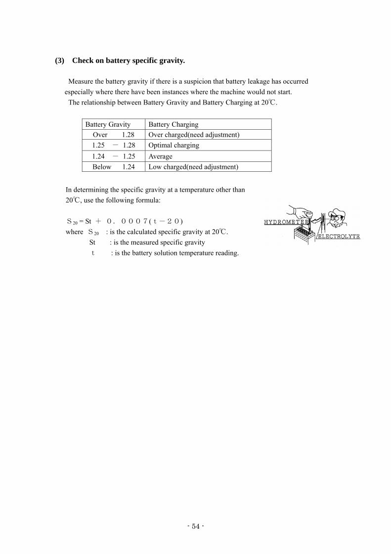
(3) Check on battery specific gravity.
Measure the battery gravity if there is a suspicion that battery leakage has occurred especially where there have been instances where the machine would not start.
The relationship between Battery Gravity and Battery Charging at 20℃.
Battery Gravity Battery Charging Over 1.28 Over charged(need adjustment) 1.25 - 1.28 Optimal charging 1.24 - 1.25 Average Below 1.24 Low charged(need adjustment)
In determining the specific gravity at a temperature other than 20℃, use the following formula: S20 = St + 0.0007(t-20) where S20 : is the calculated specific gravity at 20℃.
St : is the measured specific gravity t : is the battery solution temperature reading.
- 55 -
5-2-3 Checking/every 500 hours Checking/every 250 hours is also required.
(1) Replacement of engine oil
① Remove the engine oil drain plug and discharge oil completely. It can be discharged easily
when the engine is warm.
② After engine oil is discharged, tighten the plug firmly.
③ Charge new engine oil from the oil filler until it reaches the notched line of the "H" on
the dipstick.
④ After engine oil is supplied, run the engine for a few minutes. Check that oil is supplied to
the level between H and L .
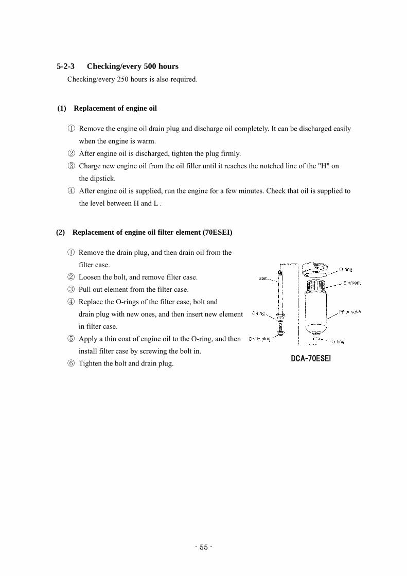
(2) Replacement of engine oil filter element (70ESEI) ① Remove the drain plug, and then drain oil from the
filter case. ② Loosen the bolt, and remove filter case. ③ Pull out element from the filter case. ④ Replace the O-rings of the filter case, bolt and
drain plug with new ones, and then insert new element in filter case.
⑤ Apply a thin coat of engine oil to the O-ring, and then install filter case by screwing the bolt in.
⑥ Tighten the bolt and drain plug.
DCA-70ESEI
- 56 -
(3) Replacement of engine oil filter element (125ESEI,180ESEI)
① Remove the cartridge type element (cartridge) using filter wrench.
② Clean the filter base. Coat the packing of new cartridge with engine oil thin. Then, mount the cartridge. ・When mounting, tighten the cartridge from
3/4 to 1 turn by using filter wrench after the packing is fitted to the seal of the filter base.
③ After the element is replaced, run the engine for a while. Then, check to see that oil is supplied to the level between H and L.
Parts number of oil filter cartridge : Model name Parts number Manufacture Parts number of manufacture
Check on the rubber suspension, whether it is damaged or deformed by the oil. Contact distributor or our office to replace the rubber suspension, if necessary.
(4) Checking on nylon and rubber hose
Check on the nylon and rubber hose, whether they are hardened or deteriorate. Contact distributor or our office to replace the nylon hose and rubber hose, if necessary.
(5) Checking on lining
Check on the lining, whether it deteriorates greatly, or it is stained by clinging of oil
or the like, or it is removed. Contact distributor or our office to replace the lining, if
necessary.
- 60 -
5-2-5 Table of periodical maintenance and checking ◇:Check or Clean ○:Replacement ●:Remove
List of maintenance and inspection
daily
first
50h
every
250h
every
500h
every
1000h
every
2 year
Checking on oil level and stain of oil ◇
Checking on cooling water ◇ ○
Checking on fan belt ◇
Checking on fuel and drain ◇ ◇
Checking on battery acid level ◇
Checking on for water and oil leakage ◇
Checking on bolts and nuts for looseness ◇
Checking on exhaust color, sound and vibration ◇
Checking on meters and warning lamps ◇
Drain the environment tank ◇
Drain water in fuel filter ◇
Clean air cleaner element ◇
Checking on specific gravity of battery ◇
Replacement of engine oil ○
Replacement of engine oil filter element ○
Cleaning feed pump strainer ◇
Cleaning electromagnetic pump filter ◇
Cleaning radiator and intercooler ◇
Drain intercooler ●
Replacement of fuel filter ★○ ○
Cleaning fuel tank ◇
Replacement of air cleaner element ○
※Inspection of engine valve clearance ◇
※Adjust fuel injection nozzle ◇
※Inspection of timing of fuel injection ◇
Checking on rubber suspension ◇
Checking on nylon and rubber hose ◇
Engine
Checking on lining ◇
Checking on insulation resistance ◇
Checking on terminal and connected section ◇
Generator
Checking on the operation of the leakage relay ◇
※ Contact distributor or our office. ★ It shortens it by the situation of the management replenishment of the fuel.
- 61 -
6. Troubleshooting
- 62 -
7. Principal data 7-1 Readings on gauges
Marking Reading Unit Engine speed 1500 min-1
Hour meter Adding up H
Engine temperature below 95 ℃
Engine oil pressure Between 2 and 5 1) ×100kPa
Battery charging voltage more than 12.5(70ESEI,125ESEI) 24.0 (180ESEI)
V
Frequency 50 Hz
Load current Below max. rating A
Voltage indicates Phase-to-phase voltage V
1) If the engine is cold, the pressure may be higher during starting. 7-2 Setting of switches
Switch Function Breaks at Unit Engine oil pressure Shut-down 0.981
1.0 ×100kPa (70ESEI,180ESEI) ×100kPa (125ESEI)
Engine coolant temperature Shut-down 105 ℃
7-3 Reference conditions Absolute inlet pressure……………………………………………………….100kPa Relative air humidity…………………………………………………………60% Air inlet temperature…………………………………………………………27℃ Generator load………………………………………………………………..continuous 7-4 Limitations Maximum ambient temperature………………………………………………40℃ Maximum altitude……………………………………………………………1000m Maximum relative air humidity………………………………………………85%
- 63 -
7-5 General specifications DCA type 70 125 180
1. Engine
I su zu , t y p e… … … … … … … … … … … … … … 4JJ1X 4HK1X 6HK1X