21
1 Instruction Manual and Maintenance instructions WEEDMASTER -

1
Instruction Manual
and
Maintenance instructions
WEEDMASTER
-

2
IMPORTANT NOTICE
This is the industry’s “Safety Alert Symbol”. This symbol is used to call your
attention to items or operations that could be dangerous to you or other persons
using this installation. Pleas read these massage carefully. It is essential that you
read the instructions and regulations before you attempt to use this installation.
Warnings: Warnings call attention to instructions which must be followed precisely to avoid
injury or death.
Caution: Cautions call attention to instructions which must be followed precisely to avoid
damaging the product, process or its surroundings.
Notes: Notes are used for supplementary information.
NOTE: In order to improve the product, the manufacturer reserves the right to make
modifications and update this publication without warning.
All reproduction, even in partial form, is forbidden without the authorization of the manufacturer.
C copyright 2016 WATERKRACHT B.V
Ensure that the operator reads and understands this manual
before maintenance or operation.

3
TECHNICAL DATA WEEDMASTER .
General: Pressure :15 bar.
Working pressure :10 bar.
Waterflow : 5 l/min.
Temperature : 0 - 98°C.
Heating : vertical high pressure coil.
Water supply connection :1/2" (2 - 6 bar, 20 liter/min.).
High pressure connection : M22 x 1,5 buitendraad.
Operating voltage : 230Volt - 50Hz.
Dimensions (B x D x H) : 87 x 59 x 85 mm.
Weight : 90 Kg.
Electricmotor:
Type : one fase electric motor.
Power : 0,25 kW – 0.34 HP
Isolation : F
Cos phi : 0,86
RPM : 1380 rpm.
Current. : 1,9 Amp at 230Volt-50Hz
Vane pump: Type :102 A 100 F 1156 A 215 / C1264.
Drive: Direct by an 230Volt - 50Hz, elektricmotor.

4
Waarschuwing - Raadpleeg het instructie- en onderhoudsboek.
Warning - Consult the operating and maintenance manual.
Attention - Consulter le manuel d’utillisation et d’entretien.
Warnung - Bedienungsanleitung lesen.
Waarschuwing - Elektrische schok risico
Warning - Electrical shock risk.
Attention - Risque d` électrocution.
Warnung - Gefährliche elektrische Spannung.
Waarschuwing - Heet oppervlak.
Warning - Hot surface.
Attention - Surface chaude.
Warnung - Heiße Oberfläche.
Waarschuwing - Bijtende vloeistof.
Warning - Corrosion risk.
Attention - Risque de corrosion.
Warnung - Ätzende Stoffe.
Waarschuwing- Lees het instructie- en onderhoudsboek voordat u gaat
draaien of onderhoud gaat uitvoeren.
Warning - Read the Operation and Maintenance manual before operation or
maintanance of this machine is undertaken.
Attention! - Lire le manuel d’utillisation et de d’maintenance de cette
machine avant d’intervenir.
Warnung - Bedienungs- u. Wartungsanleitung vor der Inbetriebnahme bzw.
Wartung lesen.
Geen open vuur.
No naked lights.
Pas de flammes nues.
Feuer, offenes Licht und Rauchen verboten.

5
INDEX
RECOMMENDATIONS FOR THE USE OF THE HIGH PRESSURE JETTING
EQUIPMENT. 6
1 GENERAL. 12
1.1 Foreword. 12
1.2 After Sales. 12
2 DESCRIPTION. 13
2.1 General. 13
2.1.1. Position. 13
2.1.2. How its works. 13
2.1.3. Safety. 13
2.2 Connections. 14
2.2.1. Water supply connection. 14
2.2.2. High pressure connection. 14
2.2.3. Electrical connection. 14
2.3 Control. 15
2.3.1. Checks before starting the high pressure unit. 15
2.3.2. Starting procedure high pressure unit. 15
2.3.3. Shutting down high pressure unit. 16
2.4 Maintenance. 17
2.4.1. General. 17
2.4.2. Maintenance high pressure pump. 17
2.4.3. Water filter. 17
2.4.4. Discaling. 17
2.5 Spare Parts list, WeedMaster . 18
3 TROUBLE SHOOTING. 19
4 TECHNICAL INFO. 20

6
RECOMMENDATIONS FOR THE USE OF THE HIGH PRESSURE JETTING
EQUIPMENT.
IMPORTANT NOTICE This is the industry's "Safety Alert Symbol". This symbol is used to call
your attention to items or operations that could be dangerous to you or
other persons using this installation. Pleas read these messages carefully.
It is essential that you read the instructions and regulations before you
attempt to use this installation.
1. Protective clothing and personal protection shall be provided to all operators of High Pressure
Water Jetting Equipment, and must be worn within the working area.
2. Avoid contact with the water jet, while it may cause serious injuries.
Never aim the water jet in the direction of persons, animals, electric equipment or the high pressure water jetting equipment itself.
3. A pressurized liquid is very dangerous if handled by incompetent persons.
Before starting maintenance or repair at high pressure water jetting equipment, be sure the system is depressurized and can not be started by accident.
4. Any persons required to operate or use High Pressure Water Jetting Equipment shall be competent to do so.
5. The Equipment shall not be used as long as any persons are within the reach of the water jet.
6. The electrical wiring shall be installed and connected by an authorized person, according to
the local regulations.
7. Eventual cable extension pieces shall be provided with watertight connectors.
8. Never pull the machine or the electrical cable to disconnect the electrical power.
9. Beware of the reaction force and twisting moment of the lance or high pressure spray gun.
The operator should be safely positioned on a rough sub soil.
Gun and lance should be held by two hands.
10. Always be sure that the equipment is working at the nominal pressure and inform any person
required to operate or use the high pressure water jetting equipment of this pressure.
11. The equipment shall not be used in case of damage of important parts, such as electrical
cable, high pressure hose, safety devices and spray gun.
12. Only by the manufacturer recommended and approved cleaning and maintenance chemicals
and/or devices shall be used. Always meet the recommendations for use.
13. All pressurized parts, in particular hoses and couplings shall be inspected regularly, be free of
faults and replaced when necessary.
14. When not in use or during service or maintenance the main switch shall be turned off, and the
system shall be depressurized by pulling the trigger of the spray gun.
15. Maintenance and repairs shall only be carried out by authorized persons.
7
16. All connected accessories and auxiliaries shall be suited for the nominal working pressure of
the equipment.
17. In case more than one high pressure water jetting equipment is connected to a joint pressure
line, reliable and suitable pressure regulating devices should be installed, and working proce-
dures shall avoid starting the equipment by accident or unintended.
18. Never use pressurized liquids for direct injection in drinking water equipment.
19. When working in a small and closed room, be sure that there is sufficient ventilation.
20. The safety device shall be regularly checked for a proper functioning.
21. Periodical, and at least once a year the safety system of the equipment shall be checked by an
authorized and skilled person.
22. When selecting the working position of the machine ensure that there is sufficient clearance
for ventilation and exhaust requirements, observing any specified minimum dimensions (to
walls, floors etc.)
23. Adequate clearance needs to be allowed around and above the machine to permit safe access
for specified maintenance tasks.
24. Ensure that the machine is positioned securely and on a stable foundation. Any risk of
movement should be removed by suitable means, especially to avoid strain on any rigged
hoses/piping.

8
FOREWORD.
The contents of this manual are considered to be proprietary and confidential to Waterkracht
B.V. and should not be reproduced without the prior written permission of Waterkracht B.V.
Nothing contained in this document is intended to extend any promise, warranty or
representation, expressed or implied, regarding the Waterkracht products described herein.
Any such warranties or other terms and conditions of sale of products, which are available
upon request.
This manual contains instructions and technical data to cover all routine operation and
scheduled maintenance tasks by operation and maintenance staff. Major overhauls are should
be referred to an authorized Waterkracht service department.
The design specification of this machine has been certified as complying with E.C. directives.
Any modification to any part is absolutely prohibited and would result in the CE certification
and marking being rendered invalid.
All components, accessories, pipes and connectors added to the high pressure system
should be:
- of good quality, procured from a reputable manufacturer and wherever possible, be of
a type approved by Waterkracht B.V.
- clearly rated for a pressure at least equal to the machine maximum allowable working
pressure.
The use of repair parts other than those included within the Waterkracht approved parts list
may create hazardous conditions over which Waterkracht has no control. Therefore Water-
kracht B.V. cannot be non-approved repair parts are installed.
Waterkracht B.V. reserves the right to make changes and improvements to products without
notice and without incurring any obligation to make such changes or add such improvements
to products sold previously.

9
SAFETY.
Warnings
Warnings call attention to instructions which must be followed precisely to avoid injury or
death.
Cautions
Cautions call attention to instructions which must be followed precisely to avoid damaging
the product, process or it surroundings.
Notes
Notes are used for supplementary information.
SAFETY PRECAUTIONS.
General information:
Ensure that the operator reads and understands the decals and consults the manuals before
maintenance or operation.
Ensure that the Operation and Maintenance manual not be removed permanently from the
machine.
Ensure that maintenance personnel are adequately trained, competent and have read the
Maintenance Manual.
Make sure that all protective covers are in place and that the doors/panels are closed during
operation.
The specification of this machine is such that the machine is not suitable for use in flammable
gas risk areas. If such an application is required then all local regulations, codes of practice
and site rules must be observed. To ensure that the machine can operate in a safe and reliable
manner, additional equipment such as gas detection, exhaust spark arrectors, and may be
required, depending on local regulations or the degree of risk involved.
High pressure water can be dangerous if incorrectly handled. Before doing any work on the
machine, ensure that all pressure is vented from the system and that the machine cannot be
started accidentally.
Ensure that the machine is operating at the rated pressure and that the rated pressure is known
to all relevant personal.
All water pressure equipment installed in or connected to the machine must have safe
working pressure ratings of at least the machine rated pressure.
High pressure water must not be used for a direct feed to any form of drinking water
apparatus.
If high pressure water is to be ultimately released into a confined space, adequate ventilation
must be provided.
When using high pressure water always use appropriate personal protective equipment.

10
All pressure containing parts, especially flexible hoses and their couplings must be regularly
inspected.
Avoid bodily contact with the water jet, while it may cause serious injuries.
The safety valve must be checked periodically for correct operation.
AVOID INHALATION
Ensure that adequate ventilation of the cooling system and exhaust gases is maintained at all
times.
The following substances are used in the manufacture of this machine and may be hazardous
to health if used incorrectly:
- engine lubricant
- preservative grease
- rust preventative
AVOID INGESTION, SKIN CONTACT AND INHALATION OF FUMES.
Transport:
When loading or transporting machines ensure that the lifting and tie down points are used.
ROUTINE MAINTENANCE.
This section refers to the various components which require periodic maintenance and
replacement.
Water under high pressure can be dangerous if incorrectly handled. Before doing any work
on the unit, ensure that all pressure is vented from the system and that the machine cannot be
started accidentally.
Ensure that maintenance personnel are adequately trained, competent and have read the
Maintenance Manual.
Prior to attempting any maintenance work, ensure that: - all pressure is fully discharged and isolated from the system.
- the machine cannot be started accidentally or otherwise, by posting warning signs
and/or fitting appropriate anti-start devices.
- all residua electrical power sources (mains and battery) are isolated.
Prior to opening or removing panels or covers to work inside a machine, ensure that: - anyone entering the machine is aware of the reduced level of protection and the
additional hazards, including hot surfaces and intermittently moving parts.
- the machine cannot be started accidentally or otherwise, by posting warning signs
and/or fitting appropriate anti-start devices.

11
Prior to attempting any maintenance work on a running machine, ensure that: - the work carried out is limited to only those tasks which require the machine to run.
- the work carried out with safety protection devices disabled or removed is limited to
only those tasks which require the machine to be running with safety protection
devices disabled or removed.
- appropriate personal protective equipment is worn.
- loose clothing, jowlier, long hair etc. is made safe.
- warning signs indicating that Maintenance Work is in Progress are posted in a
position that can be clearly seen.
Upon completion of maintenance tasks and prior to returning the machine into service,
ensure that:
- the machine is suitable tested.
- all guards and safety protection devices are refitted.
- all panels are replaced and doors closed.
- hazardous materials are effectively contained and disposed of.
DECOMMISSIONING.
When the machine is to be permanently decommissioned or dismantled, it is important to
ensure that all hazard risks are either eliminated or notified to the recipient of the machine.
In particular:
- do not destroy batteries or components containing asbestos without containing the
materials safely.
- do not dispose of any pressure vessel that is not clearly marked with its relevant data
plate information or rendered unusable by drilling, cutting etc.
- do not allow lubricants or coolants to be released into land surfaces or drains.
- do not dispose of a complete machine without documentation relating to instructions
for it use.
12
1. GENERAL
1.1. FOREWORD.
Waterkracht automatic switching installations type "WeedMaster".
"WeedMaster" cleaning installations adjust the power delivered according to the duty of
the cleaning application.
A Waterkracht installation delivers the optimum amount of cleaning power demanded by
each specific cleaning problem. There is no energy wasted by overcapacity.
Waterkracht cleaning is made to measure.
The pump raise the pressure in the pipe system up to the selected maximum working
pressure. If no water is withdrawn from the tapping points pumping stops, after a period of
free running.
The installations are supplied in diverse working pressures and water capacities, dependent
on the desired specifications.
- A technical balanced "building block" system ensures an appropriate installation.
- As regards implementation, adoptions can be made to suit the company's
circumstances.
- The installation can be connected to either a cold water supply or to a hot water
supply with a maximum temperature of 50° C.
- The heart of the system is one industrial three-plunger high pressure pump, tried and
tested in practice.
- A sophisticated sequential switch controls the starting and stopping of the pump,
which will save energy and maintenance costs.
- Servicing or repair of one pump unit is possible without disconnecting the main
system.
- Detergents can be added either centrally or separately at each tapping point.
- Existing Waterkracht stationary installations can be extended at any time.
The advice of Waterkracht specialists covers many areas and includes the selection not only
of high pressure installations, but also of specific detergents and accessories exactly attuned
to the type of dirt to be combated. Complete "turn-key" projects in hospitals, large kitchens,
breweries, abattoirs, transport sector, off-shore installations, agricultural sector, foodstuffs
industry and lastly but certainly not least: the armed forces, where Waterkracht is
prominently involved in rapid developments in modern company equipment for the cleaning
of aircrafts, ships, tanks, diverse components, etc.
1.2. AFTER SALES.
Quick service is supported by thirteen fully equipped service cars from several places in
Holland.
Waterkracht customers can concluse service contracts for their high pressure cleaning units to
be assured of regular maintenance. This will increase the reliability of the unit.

13
2 DESCRIPTION.
2.1 General.
The machine is build up with the following components:
* Pump
* Electric motor.
* Pressure regulator.
* Burner.
On the machine is the switchbox mounted, provided with main switch, 0-1-2
switch,(off-cold-hot).
2.1.1. Position.
* The machine may not be operated in areas when there is a risk of
explosion.
* If the machine is exposed to a risk of frost during use, then frost-protetive measures are to be
carried out to prevent the destruction of parts or subassemblies.
* When the machine is operating indoors, ensure thar the combustion gasses are expelled
safely. The device may only be disconnected from the fleu connection for service purposes.
* Exhaust systems must be dimensioned in accordance with lateral and vertical clearance
requirements so that the exhaust fumes can be expelled into the open air in all correct
operating states.
2.1.2. How it works.
The pump raise the pressure in the pipe system up to the selected maximum working pressure. If no
water is withdrawn from the tapping point pumping stops.
The automatic Start/Stop system is an important part of the WeedMaster. It switches of the
pumpunit on and off. When no water is drawn from the unit, the pressure regulator will be set on
"by-pass" so that the water of the pump flows back to the suction side of the pump. This will be
detected through a flow switch and the pump will be switched off. When the pressure in the high
pressure system falls down (by opening a spray gun), the automatic unloader valve switches back to
normal operation, and a pressure switch will start the pumpunit.
2.1.3. Safety. The WeedMaster is equipped with an max. thermostat (mounted in the switch box), pressure gauge,
safety valve and a pressure regulator.
14
2.2 Connections.
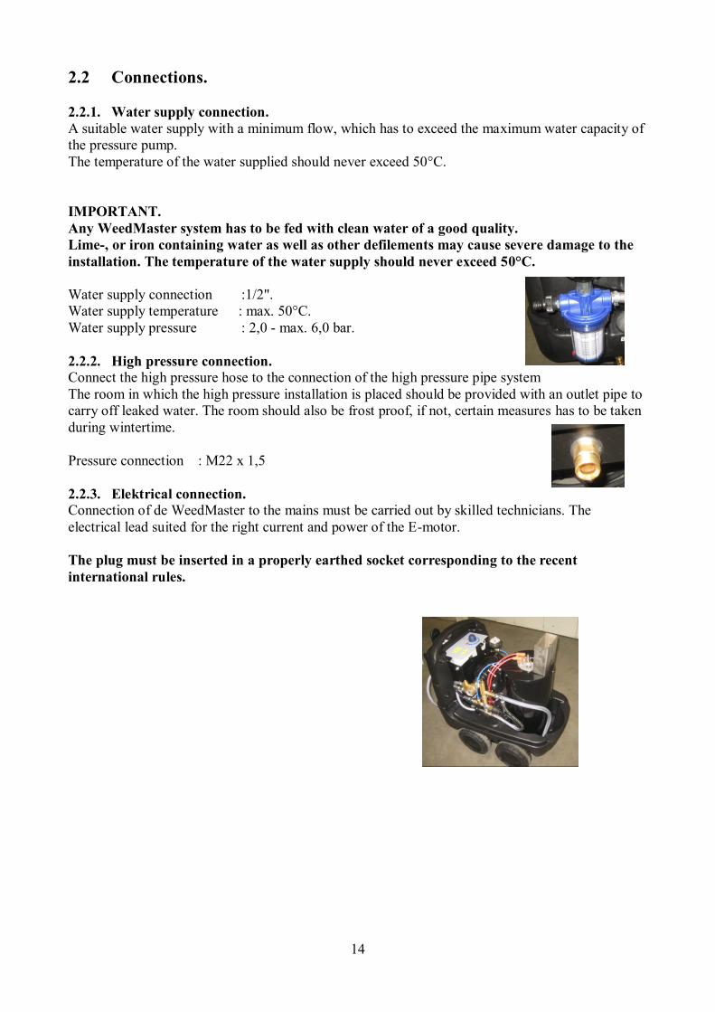
2.2.1. Water supply connection.
A suitable water supply with a minimum flow, which has to exceed the maximum water capacity of
the pressure pump.
The temperature of the water supplied should never exceed 50°C.
IMPORTANT.
Any WeedMaster system has to be fed with clean water of a good quality.
Lime-, or iron containing water as well as other defilements may cause severe damage to the
installation. The temperature of the water supply should never exceed 50°C.
Water supply connection :1/2".
Water supply temperature : max. 50°C.
Water supply pressure : 2,0 - max. 6,0 bar.
2.2.2. High pressure connection. Connect the high pressure hose to the connection of the high pressure pipe system
The room in which the high pressure installation is placed should be provided with an outlet pipe to
carry off leaked water. The room should also be frost proof, if not, certain measures has to be taken
during wintertime.
Pressure connection : M22 x 1,5
2.2.3. Elektrical connection. Connection of de WeedMaster to the mains must be carried out by skilled technicians. The
electrical lead suited for the right current and power of the E-motor.
The plug must be inserted in a properly earthed socket corresponding to the recent
international rules.

15
2.3 Operation.
2.3.1. Checks before starting the WeedMaster.
To prevent trouble and accidents, it is important to keep the installation in top condition. Always
check the following points before starting the WeedMaster.
IMPORTANT.
Prevention of accidents.
The unit is designed to minimize the risks of accidents under normal operation
circumstances. Special attention should be payed to the use of the spraying
guns. The water jet is as sharp as a knife. Therefore never spray in the direction
of living creatures.
When using a safety spray lance, mind that the recoil and the angular lance will produce a
certain torque which will increase with greater length of the lance.
1. Check water filter, for dirt and leaks.
2. Check if there are no leaks in the suction hose and connections.
3. Correct connections of hoses, spraying guns en nozzles.
4. Before starting the machine, besure that all the side penals are closed.
2.3.2. Starting procedure high pressure unit.
WARNING!
Before starting this machine besure there are no persons in a hazardous position
of the machine. Any warnings necessary have been suitable displayed (where
applicable).
When the points described above are oke, you can start the high pressure unit:
1. Connect the watersupply hose to the watersupply connection of the machine.
2. Connect the high pressure hose to the tapping point and connect the high pressure spraying
gun to the high pressure hose.
3. Put the start switch to position “1”, the pump wil start and put the system unther the adjusted
pressure.
4. Open the spraying gun and start cleaning.
5. During use you can adjust the working pressure up to a maximum to 10 bar
6. When cleaning with hot water, turn swich from position “1” to position “2”.
WARNING!
The waterjet is as sharp as a knife.
Therefore never spray in the direction of people, animals, power sockets or
electric appliances.

16
2.3.3. Shutting down the high pressure unit.
1. After using hot water, turn the operating switch from position “2” to position “1” (Cold
water) keep on working till the water flow is cooled down, it takes some minutes.
2. Release the trigger of the spray gun. After a period of idling time the pump unit will stop.
3. Stop the machine, turn switch to the left in position “0".
4. Pull the trigger of the spray gun to release the pressure in the high pressure hose.
5. Disconnect the high pressure hose.
6. When the pump unit is not in use for a longer period (over night or weekend), it is necessary
to take the power plug out of the earthed socket.
N.B.
After shutting down the machine or after working with the machine, turn
mainswitch to position “0”

17
2.4 Maintenance.
2.4.1. General.
The machine must be at least one or two times on a year maintenance.
Punctual and accurate execution of maintenance will increase the reliability and service life of
the installation.
CAUTION.
Disconnect the machine from the mains before carrying out any maintenance
work, close the water lines and depressurize the system.
Be sure the unit is switched off, when maintenance or repairs are taking place.
ATTENTION.
Before carrying out any maintenance or repairs, be sure the pump unit is
switched off. Once maintenance or repairs are completed, and all the protecting
panels have been correctly placed, the pump unit can be started again.
2.4.2. Water filter.
The filter must be cleaned regularly.
Stopped up filter, leakages in the suction side of the pump or
defective pump valves may cause heavy pump vibrations, which
will effectuate in serious pump damage.
WARNING !
NEVER LET THE PUMP RUN DRY
2.4.3. Lime binder dosing pump.
For adding lime binder liquid a lime binder dosing pump
is mounted.
Tank cap for lime liquid

18
2.5 Spare Parts list, WEEDMASTER.
Pos. no;
1. Water supply. 1a Water filter ½” Wk nr.: 217766
Filter element 10 micron Wk nr.: 217767
Pos. no;
2. Pump.
Vane pump type: 102 A 100 F 1156 A215 / C1264
- Pressure : 15 bar
- Working pressure : 10 bar
- Water flow : 5.0 l / min.
- Max. water temperature : 50°C
Pos. no;
3. Electric motor (+pump) Wk.nr.: 219563
Type : AC1
Voltage : 230V – 50 HZ
Power : 0.25 KW – 0.34 HP
Speed : 1380 Rpm
Pos. no;
4. Pressure group. 4a Pressure gauge, 0-25 bar ¼" connection, Wk.nr.: 201213
4b Pressure regulator, 10 bar – 35 l/min Wk.nr.: 268551
4c Flow switch, 250 bar – 30 l/min Wk.nr.: 272555
Reed switch, ( flow) Wk.nr.: 272557
4d Pressure switch, 1-10 bar ¼”connection Wk.nr.: 272092
4e Safety valve, VS 160 Wk.nr.: 203432
4f Burner, Wk.nr.:
Dosingpump limebind fluid 230V Wk.nr.: 276425
Restriction nozzle 0.2 mm Wk.nr.: 250340
Pistol grip RL20 Wk.nr.: 306864
Spray lance 1.2 m Wk.nr.: 275922

19
Pos. nr;
6. Switch box.
6a Switch, 0-1-2 Wk.nr.:
Pos. nr;
7. High pressure connection.
- M22 x 1,5 bui.dr. Wk.nr: 250215
Fuel – level security Fuel pump + Max. thermostat
Water supply connection.
Lime binder liquid filler
and fuel filler cap.

20
3 TROUBLE SHOOTING.
A. Pumpunit fails to start:
1. No current or wrong voltage,
- check electricity supply.
2. Main switch is put on "0",
- put it on "1".
3. Circuit breakers are jumped out,
- reset the circuit breakers.
Be sure the cause of the failure is corrected before resetting the circuit breakers.
B. Pumpunit starts, but stops after a short period:
1. Water supply is not sufficient.
- check the water supply.
C. Pump runs but fails to reach required pressure:
1. Close the high pressure ball valves on the pumpunit. If the pressure on the unit rises, there
will be leaks in the high-pressure pipe system, if the pressure stays low, there is a failure in
the pumpunit,
- check and repair.
2. Suction filter is stopped up,
- clean suction filter.
3. Suction hose and/or connections are leaky,
- check and repair.
NOTE: Never let the pump run dry !!
4. Filthy or wrong adjusted Automatic unloader valve,
- clean or adjust if necessary.
5. Wrong or worn out nozzle in the spraying gun,
- Check the number and type of the spraying nozzle in the spraying gun and replace if
necessary. The total water capacity of the nozzle at the working pressure has to be lower
than the water capacity of the pump.
D. Heavy pump vibrations.
1. Pump sucks air,
- check suction hose and connections.
2. Suction filter is stopped up,
- clean filter.
NOTE: Heavy pump vibrations may cause serious pump damage.

21
E. Pumpunit fails to stop.
1. Leaks in the high pressure pipe system,
- check and repair if necessary.
2. Defective or wrong adjusted pressure switch,
- replace or adjust.
3. Defective or wrong adjusted flow switch,
- replace or adjust.
4 TECHNICAL INFORMATION.
- Pressure regulator, ;. Spare parts list and exploded vieuw
- Safty valve ; Spare parts list and exploded vieuw.
- Flow ; Spare parts list and exploded vieuw.
- Flow-schedule
- Electric-schedule


