1 SUPER AIRFLOW CONVERTER SUPER AIRFLOW CONVERTER INSTRUCTION MANUAL Thank you for purchasing the APEXERA Super Airflow Converter. Please read through this Instruction Manual to oper- ate this product correctly and keep it near the product so that you may refer to it whenever necessary. If you trans- fer the product to another customer, be sure to attach this Instruction Manual and the warranty to the product. SUPER AFCⅡ 401-A911/401-A913 Car models mentioned in the wiring diagram by model Airflow/pressure sensor signal adjustment Product name Product code Applicable car models Application
Transcript
1
SUPERAIRFLOW CONVERTER
SUPER AIRFLOW CONVERTER
INSTRUCTION MANUAL
Thank you for purchasing the APEXERA
Super Airflow Converter. Please read
through this Instruction Manual to oper-
ate this product correctly and keep it
near the product so that you may refer
to it whenever necessary. If you trans-
fer the product to another customer, be
sure to attach this Instruction Manual
and the warranty to the product.
SUPER AFCⅡ
401-A911/401-A913
Car models mentioned in the wiring diagram by model
Airflow/pressure sensor signal adjustment
Product name
Product code
Applicable car models
Application
2
Contents Chapter 1 Introduction
Safety Precautions __________________________________________________________ 4 Features of this Product _____________________________________________________ 6
Names and Functions of Parts ________________________________________________ 8
Parts list ...............................................................................................................8 Names of parts .....................................................................................................8 Meanings of operation symbols appearing in this document .....................................8
Chapter 2 Initial Setup Procedure before Using This Product __________________________________________ 12 Perform initial setup. _______________________________________________________ 13 Setting the sensor type and sensor number【Sensor Type】..........................................13
Setting the number of cylinders 【Car Select】 .................................................... 13 Checking the throttle sensor voltage【Sensor chk】 ............................................ 13 Setting the throttle sensor type 【Car Select】 .................................................... 13 Learning the throttle opening .............................................................................. 13 Correcting the knocking signal 【Knk Set】.......................................................... 13
Chapter 3 Outline of Operating Method Outline of Functions and Operating Method _____________________________________ 16
Functions and Operations in monitor mode _____________________________________ 18
Functions and Operations in the setting mode __________________________________ 19
Functions and Operations in the etc, mode______________________________________ 19
Safety Precautions ___________________________________ 4 Features of this Product ______________________________ 6
Names and Functions of Parts _________________________ 8 Parts list .................................................................................8 Names of parts .......................................................................9 Meanings of operation symbols appearing in this document ..... 9
4
●Do not use this product for any application other than applicable vehicles or
applicable goods . We shall disclaim the responsibility for operations in an application other than the applic
able vehicles or applicable goods. It will result in an unexpected accident.
●If this product gives out any abnormal noise or offensive smell, stop operati
ng the product immediately. Using the product in this status will result in an electric shock, fire, or damage of elec-
tric parts. Consult the distributor or your nearest business office for information.
●Do not use this product and its accessories in any way other than specified
by A’PEX. In this case, we shall disclaim all responsibility for any damage or loss to the customer
and third persons.
●Do not turn on and/or off immediately during and after operating the key Set/recorded data may be lost.
Safety Precautions
Please read “Safety Precau-
tions” carefully to operate
the product with safety.
Keep the Instruction Manual
in hand and refer to it when-
ever needed.
The Instruction Manual de-
scribes the items that you
must observe to operate the
product without giving any
injury to you, other people
and damage to property. The
meanings of pictorial indica-
tions (signal words) are as
shown on right. Please un-
derstand their contents cor-
rectly before starting to read
the text.
■Explanation of indications
This indicates the existence of potential
hazard that will result in death or seri-
ous injury of the operator or a third
person if the product is wrongly oper-
ated in disregard of this indication.
This indicates the existence of potential
hazard that will result in slight injury
or medium damage to the operator or a
third person, and that will result in only
physical damage if the product is
wrongly operated in disregard of this
indication.
This indicates the contents of a failure
in obtaining the full performance of the
product, or a product failure or faulty
function item if the product is wrongly
operated in disregard of this indication.
Meaning Indication
WARNING !
CAUTION !
REQUEST
WARNING !
5
●The driver must not operate this product during driving This may interfere with driving operations, resulting in an accident.
●Mount this product securely. Do not install it in an unstable place that
may interfere with driving
This may interfere with driving, resulting in an accident.
●When installing the product, remove the negative terminal of the battery
beforehand A fire may be caused by short circuit or electric parts may be damaged or burnt out
●When removing a coupler, be sure to hold the coupler without pulling the
harness If the harness is pulled, a fire may be caused by short circuit or electric parts may be
damaged or burnt out
●Be sure to perform wiring in accordance with the contents described in the
Instruction Manual Incorrect wiring will result in a fire or other accidents
●If any adjustment must be made during actual driving, take special care not
to interfere with other traffic, observing the traffic laws and regulations
It will interfere with driving, resulting in an accident
WARNING !
●Regarding the installation of this product, be sure that it is installed by an
experienced professional Installing the product requires technical knowledge and skill. Be sure that the installer
installs the unit securely
●Do not tamper, disassemble, or modify this product This may cause an accident, fire, electric shock, or electric parts will be damaged or
burnt out
●Do not drop this product or expose it to strong shock This may cause a malfunction, thereby giving damage to the product and the vehicle
●Do not operate this product under direct sunlight or in high-temperature
vehicle interiors that are not air-conditioned in the summer season A malfunction will be caused, thereby giving damage to the product and the vehicle
●Do not install the product in a high-temperature place or in a place exposed
to direct water It will cause an electric shock or fire, or electric parts will be damaged. The malfunction
may damage the vehicle
CAUTION !
6
Features of this Product The SUPER AFC II is a fuel adjustment controller in which the airflow sensor signal or the p
ressure sensor signal can be modified in a 12 point RPM range by 1% increments to increas
e/decrease fuel in a range of +50% to -50%. The RPM to be corrected can be optionally se
t in 200 RPM increments, and corrections can be made according to throttle opening amoun
ts. In a turbo equipped vehicle with a hot wire type airflow meter, this controller provides a
preventive function for engine stall due to blow-back during throttle return. The controller,
which includes a knocking meter, allows the monitoring of knock levels check keeping the en
gine under its optimum condition at all times. (Vehicle must have a factory knock sensor)
●This product cannot be used for any application other than the vehicles
mentioned in the separate Vehicle Specific Application Charts ●Note that noise interference may be caused to radio, TV, etc. depending
on the mounting location of this product and the routing of the signal
harness ●This product generates heat in the power ON status. This is not abnormal
CAUTION !
■Unconventional large screen monitor using a high-brightness VFD The futuristic front face of this unit uses the large screen, high-brightness and easy to
read VFD (Vacuum Fluorescent Display)
Use of the dot-matrix large screen monitor allows the displaying several types of
information simultaneously. Display variations are not limited to only numeric value
display, but also graph display, analog display, and other various displays are shown.
This allows the driver to recognize important information in an instant
■Utilizes a thin case and single button A thin case of 52mm(L) × 126mm(W) × 18mm(D) (Minimum) has been achieved by op
timization of the circuit board and case design. The product can be easily installed on t
he steering column or dash board. Since there is no separate unit besides the main unit
it is not necessary to secure a place for installing any separate unit. Using a 4-direction
switch with a center pushbutton and a rotary switch gets rid of the button-to-button
distance and permits quick operations, thereby providing efficient operation of the unit
■Battery-less memory that can keep initial setup data in the memory even if
the vehicle battery is disconnected With the use of the EEPROM, the initial setup data is not lost unless initialization is perf
ormed, even if the power supply is turned off or the vehicle battery is disconnected. The
setting data, such as peak value and correction value, is never lost. Accordingly, if the
vehicle battery is disconnected for service inspection, initial setup and settings do not
need to be performed again and the data history is not lost
7
■Storing two patterns of setting data in the memory Two patterns of setting data including air correction factor, throttle opening, air correcti
on engine revolution speed, deceleration air upper limit, etc. can be stored in the memory.
There are two files that can be stored in the memory. The setting data can be selected i
n an instant according to each driving stage such as circuit driving, town driving, and wi
nding driving. When driving on the same stage, two patterns of setting data can be com
pared. These patterns of setting data can be used for various purposes
■Setting disable function by password If the setting data or initial set points are changed by misoperation or mischief, the car c
ondition may be deteriorated, or in the worst case, the engine may be damaged. In the S
AFC2 II, when the user sets a password optionally, changing the setting data or initial se
tup items is disabled
■Warning function to make hazard known It is possible to set warning values for the airflow using ratio, suction tube pressure, Kar
man swirl sensor frequency, knocking, and engine revolution speed When each item is set, the car condition can be precisely judged. The setting for the eng
ine speed can also be used as a shift timing point
◆Knocking Spontaneous ignition is caused by the heat and pressure of mixed air in the burning
portion of non-combustion gas far from the plug and the heat of combustion chamber
wall, so that the gas in the whole combustion chamber generates high-pressure waves
momentarily. In this phenomenon, strong metallic noise is output from the engine unlike
car knocking by which the car body becomes jerky, with the result that the valve is
damaged and the piston is seized, thereby giving fatal damage to the engine.
As countermeasures, fuel adjustment, ignition timing adjustment, compression ratio
adjustment, improvement of intake-side squish area, use of mirror type combustion room
wall, and profile improvement of the exhaust-side cam shaft can be mentioned
●During driving, the driver must not operate this product in any case It will interfere with driving operations or result in an accident
●On general public roads, observe the road and traffic law to drive the
car carefully
WARNING !
8
Names and Functions of Parts ■Parts list Before installing this product, be sure to check the parts list to confirm that there are not
any foreign or missing parts. If any difference is found between the actual parts and the
parts list, please contact the dealer of purchase.
1.Main unit 2.Instruction manual(Operation part) 3.Wiring diagram by model 4.Collection of setting data
WIRING DIAGRAM BY MODEL COLLECTION OF SETTING DATA
9
●Popup menu
When you press the center pushbutton, the popup menu shown at
right appears. The selected portion will appear as a reverse display.
Make a selection by the upper/lower/left/right part of the center
switch and decide the selection by pushing the center pushbutton
The meanings of alphabetic characters are as follows
Tp[TOP] ...... Go back to the main menu
Nx[NEXT] ..... Go to the next
Pr[PREVIOUS]. Go back to the previous
Cn[CANCEL] .. Cancel the popup menu
Nx Example) Press the center pushbutton and select [Nx] in
the popup menu
4-direction switch with a
center pushbutton
Rotary switch
SUPERAIRFLOW CONVERTER
Optical sensor
(CDS sensor) VFD display section
■Names of parts
■Meanings of operation symbols appearing in this document
※Press the right part of the
center switch
※Press the upper part of the center
switch
※Press the left part of the center
switch
※Press the lower part of the
center switch
※Press the center pushbutton
※Turn the rotary switch counterclockwise or clockwise When the rotary switch is turned clockwise, the numeric value shifts in the
positive direction or the cursor moves upward.
When the rotary switch is turned counterclockwise, the numeric value shifts in
the negative direction and the cursor moves downward. The upper/lower part
of the center switch has the same function as the rotary switch
10
11
第2章 Chapter 2
Procedure before Using This Product ___________________ 12 Perform initial setup _________________________________ 13
Setting the sensor type and sensor number ............................13 Setting the number of cylinders ..............................................13 Checking the throttle sensor voltage ......................................13 Setting the throttle sensor type .............................................13 Learning the throttle opening .................................................13 Correcting the knocking signal ...............................................13
Initial Setup
12
Procedure before Using This Product Install this product The details of the installation procedure are described in the separate “Vehicle Specific Wiring Diagram.”
Install the product securely referring to the “Vehicle Specific Wiring Diagram” in a separate document
Turn on the ignition switch Make sure that any abnormal noise or offensive smell is not produced from the SAFC II and the vehicle
Turn the ignition switch off The setting data is stored in the memory
Start the engine
Perform initial setup Perform initial setup securely by referring to page 13
●If no display appears or any abnormal noise or offensive smell is produced
from this product despite proper installation, discontinue operation of the
product immediately and contact the dealer of purchase
CAUTION !
13
● Do not start the engine before starting the initial setup
If the engine is started without initial setup, the engine may be damaged
WARNING !
Perform initial setup To operate this product, you must set several items during initial setup.
After making sure that the SAFC II is securely installed, turn on the ignition switch and select the
ETC. (etc. mode) in the main menu.
Table of initial setup items 1.Setting the sensor type and sensor number (P.44 [Sensor Type])
Select Sensor Type and set the sensor type and sensor number For vehicles equipped with a hot wire sensor, set the sensor output calculation method.
2.Setting the number of cylinders (P.50 [Car Select]) Select Sensor Type and set the number of cylinders You can select it in the range of 1 to 16 cylinders Rotary engine car: Number of rotors ×2
Mazda Atenza (GG#S/P, GY #W):2 Demio(DY♯W):1
Toyota V8 engine car:4 PASSO(KGC10):1
Nissan Fairlady Z (Z33):1 SKYLINE(CPV35):1
Daihatsu Boon(M300S):1
※For a car without throttle sensor signal, start operations from 6.
3.Checking the throttle sensor voltage (P.52 [Sensor chk])
Select Sensor chk and check the throttle sensor voltage with the throttle fully closed and once
with the throttle fully open.
4.Setting the throttle sensor type (P.50 [Car Select]) Select Car Select. When the throttle sensor voltage is 0 V to 1 V fully closed in the previous
step, set the arrow to the upward direction. When the throttle voltage is 3 V to 5 V, set the
arrow to the downward direction. When the arrow is set to the ** mark , no correction is per-
formed by throttle opening .
5.Self Learning the throttle angle Self Learn the throttle angle. While indicating throttle angle in monitor mode, Make sure to see
the throttle angle”0”when the throttle is fully closed.
Then, keep the throttle opened before the throttle angle attains 100% with indication.
※Note: It takes around 60 seconds for self learning depends on the model.
6.Turn off the ignition switch
When the ignition switch is turned off, the set items are stored in the memory
※After this, the initial setup is completed for a car without any knocking signal. For a car with a
knocking signal, perform setting 7
7.Correcting the knocking signal (P.38 [Knk Set]) Start the engine and perform warming-up. After completion of warming-up, select Setting
(setting mode) in the SAFC II main menu and select the knocking signal correction mode. Cor-
rect the knocking signal .
14
15
Chapter 3 Outline of Operating Method
Outline of Functions and Operating Method ___________ 16
What to be performed in the monitor mode ___________ 18
What to be performed in the setting mode ___________ 19
What to be performed in the etc. mode ______________ 19
16
Outline of Functions and
Operating Method
Main menu The SAFCⅡ consists mainly of 3 menus
Monitor mode The data obtained from the sensor is displayed
The airflow usage
ratio, intake pres-
sure, Karman sensor
frequency, throttle
opening, engine RPM,
air correction factor,
knocking level, and
battery voltage are
displayed
Setting mode This mode is used for the user to perform
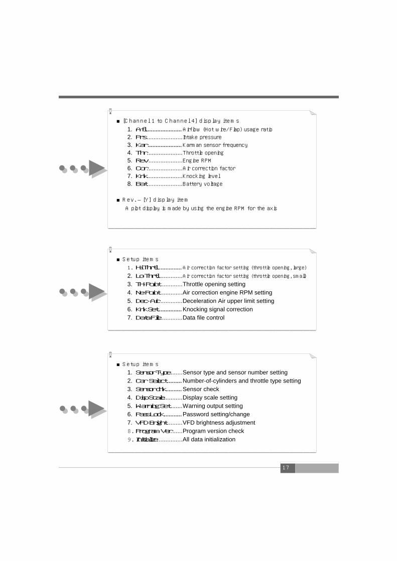
settings The air correction factor,throttle open-ing, air correction, engine RPM, and the upper limit for deceleration air is set. Knocking signal correction and data file are also controlled.
etc. mode This mode is used to perform various
settings including initial setup The initial setup, dis-
1. Sensor Type .......Sensor type and sensor number setting 2. Car Select ......... Number-of-cylinders and throttle type setting 3. Sensor chk.......... Sensor check 4. Disp Scale ...........Display scale setting 5. Warning Set........Warning output setting 6. Pass Lock ........... Password setting/change 7. VFD Bright..........VFD brightness adjustment 8. Program Ver.......Program version check 9. Initialize ...............All data initialization
18
Functions and Operations in the monitor mode Main menu 【Monitor】
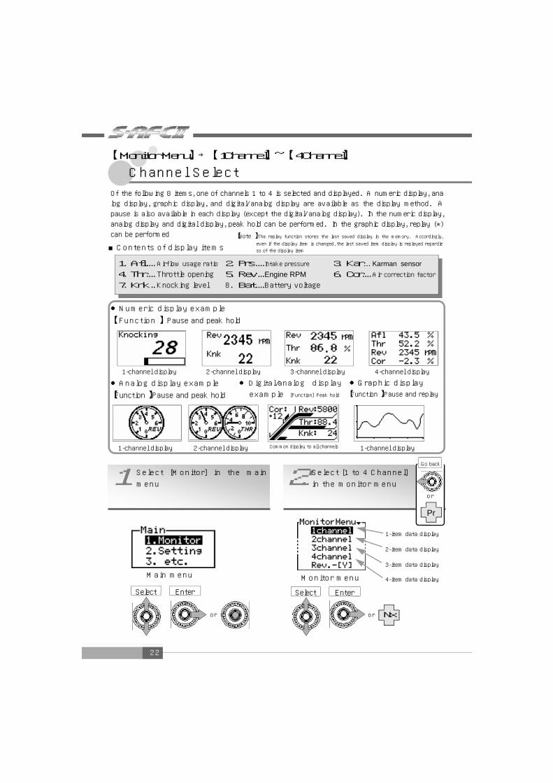
[Contents of items ] 1. Afl ..................Airflow (Hot wire/Flap) usage ratio 2. Prs ................Intake pressure 3. Kar................Karman sensor frequency 4. Thr................Throttle opening 5. Rev...............Engine RPM 6. Cor ...............Air correction factor 7. Knk ...............Knocking level 8. Bat .................Battery voltage
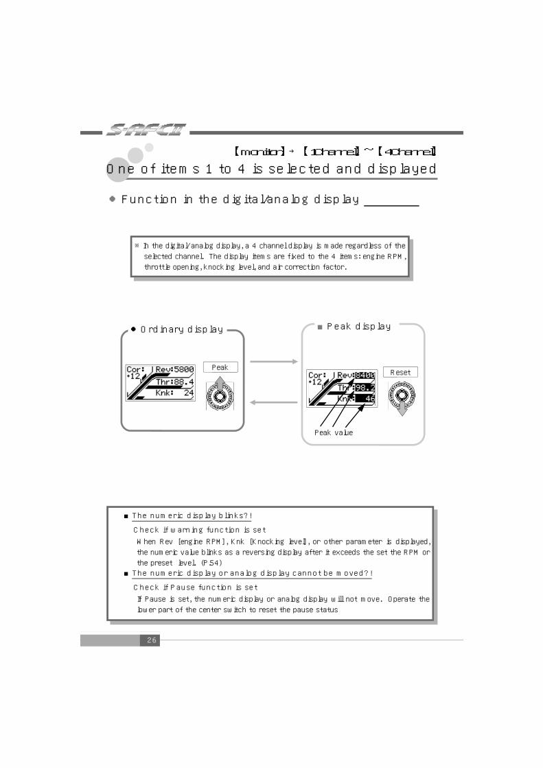
[Display method ] Numeric display/analog display : Real-time display, peak hold display, and pause
Graphic display : Real-time display, replay , and pause Digital/analog display : Real-time display, peak hold display
【One of items 1 to 4 is selected and displayed 】
P22.【Monitor】→【1Channel】~【4Channel】
【A plot display is made by using the engine RPM for the
axis 】
P27.【Monitor】→【Rev.-[Y]】
●Regarding the 3 items Afl, Prs, and Kar, the contents that can be
displayed depend on the intake air volume measuring equipment of the
vehicle. For example, in the case of a car equipped with a hot wire type
airflow sensor, Afl can be displayed but Prs is not displayed
NOTE
[Contents of the axis ]One of the 5 items is selected and displayed 1. Air Flow........Airflow (Hot wire/Flap) usage ratio 2. Pressure...... Intake pressure 3. Karman ........Karman sensor frequency 4. Throttle .......Throttle opening 5. Correct ........Air correction factor
[Display method ]
1-point display, 10-point display, and locus display
.............Real-time display, replay, and pause
19
Functions and Operations in the setting mode Main menu 【Setting】
Functions and Operations in the etc. mode Main menu 【etc.】
1.Sensor Type ............................................................................................P44 Sensor type and sensor number setting
2.Car Select................................................................................................P50 Number-of-cylinders and throttle sensor type setting
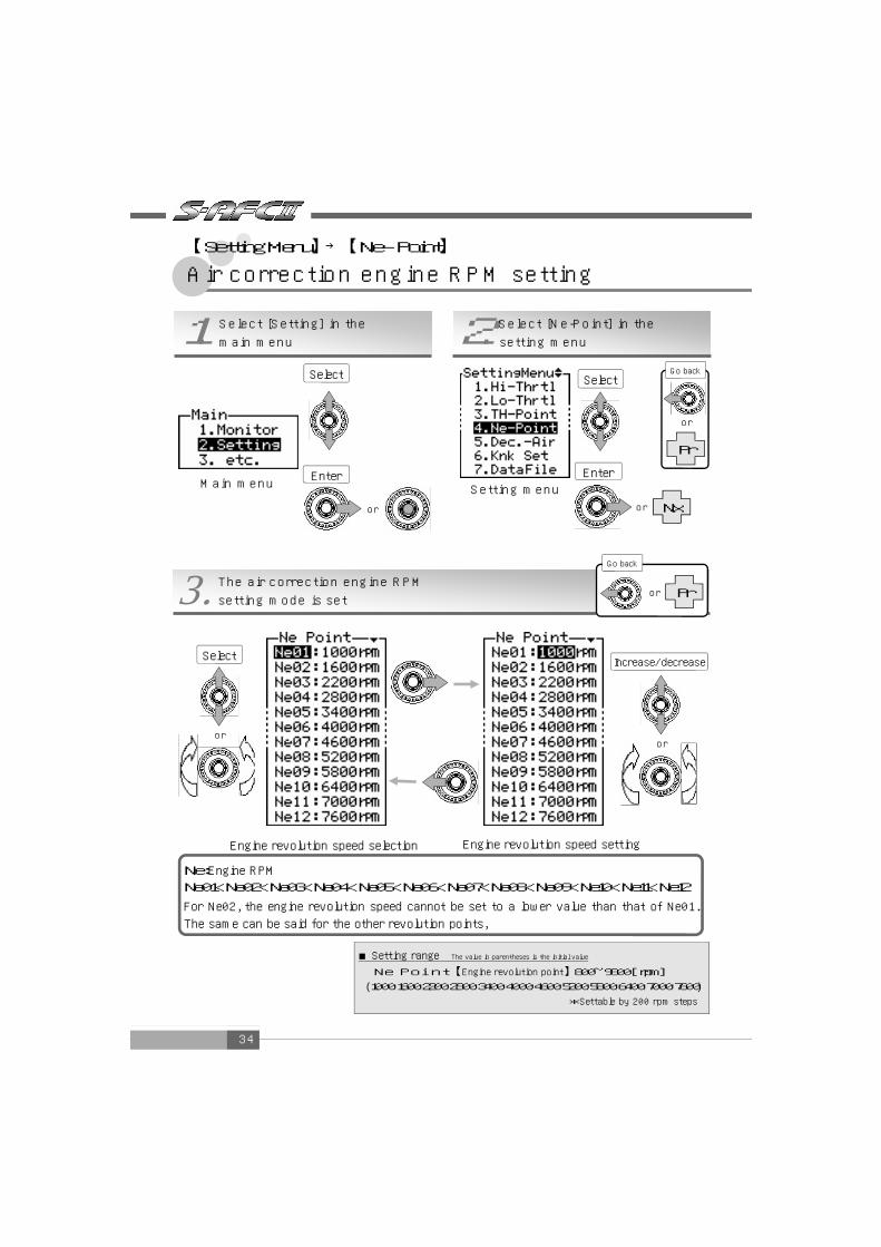
4.NeーPoint.................................................................................................P34 Air correction engine revolution speed setting
5.Dec-Air...................................................................................................P36 Reduction gear upper limit setting (for the hot wire car only)
6.Knk Set ....................................................................................................P38 Knocking signal correction
7.Data File...................................................................................................P40 Data file control
20
21
One of items 1 to 4 is selected and displayed _________22 A plot display is made by using the RPM for the axis 27
Chapter 4 Monitor Mode
22
●Graphic display 【Function 】Pause and replay
Of the following 8 items, one of channels 1 to 4 is selected and displayed. A numeric display, ana
log display, graphic display, and digital/analog display are available as the display method. A
pause is also available in each display (except the digital/analog display). In the numeric display,
analog display and digital display, peak hold can be performed. In the graphic display, replay (*)
can be performed
2. Select [1 to 4 Channel] in the monitor menu 1. Select [Monitor] in the main
menu
Main menu
【Note 】The replay function stores the last saved display in the memory. Accordingly, even if the display item is changed, the last saved item display is replayed regardle
Air correction engine RPM setting __________________ 34
Deceleration air upper limit setting __________________ 36
Knocking signal correction _____________________________________ 38
Data file ________________________________________ 40
30
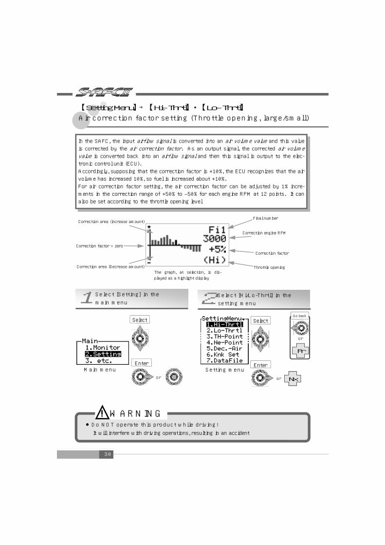
【Setting Menu】→【Hi-Thrtl】・【Lo-Thrtl】 Air correction factor setting (Throttle opening, large/small)
or
Setting menu
Correction factor = zero
The graph, at selection, is dis-
played as a highlight display
Correction area (Decrease amount)
Correction factor
Throttle opening
Correction area (increase amount)
Correction engine RPM
Final number
2. Select [Hi/Lo-Thrtl] in the setting menu 1. Select [Setting] in the main menu
In the SAFC, the input airflow signal is converted into an air volume value and this value is corrected by the air correction factor. As an output signal, the corrected air volume value is converted back into an airflow signal and then this signal is output to the elec-tronic control unit (ECU).
Accordingly, supposing that the correction factor is +10%, the ECU recognizes that the air
volume has increased 10%, so fuel is increased about +10%.
For air correction factor setting, the air correction factor can be adjusted by 1% incre-
ments in the correction range of +50% to –50% for each engine RPM at 12 points. It can also be set according to the throttle opening level
●Do NOT operate this product while driving! It will interfere with driving operations, resulting in an accident
WARNING !
Select
or
Enter Main menu
or
Nx
Pr
Select
Enter
Go back
31
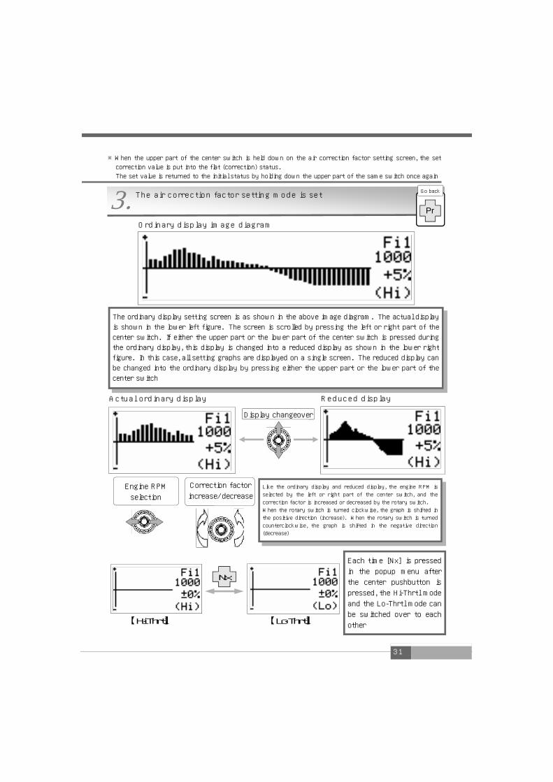
Ordinary display image diagram
Reduced display Actual ordinary display
【Hi-Thrtl】
※When the upper part of the center switch is held down on the air correction factor setting screen, the set
correction value is put into the flat (correction) status.
The set value is returned to the initial status by holding down the upper part of the same switch once again
3. The air correction factor setting mode is set
【Lo-Thrtl】
Nx
Each time [Nx] is pressed
in the popup menu after
the center pushbutton is
pressed, the Hi-Thrtl mode
and the Lo-Thrtl mode can
be switched over to each
other
Engine RPM
selection
Display changeover
The ordinary display setting screen is as shown in the above image diagram. The actual display
is shown in the lower left figure. The screen is scrolled by pressing the left or right part of the
center switch. If either the upper part or the lower part of the center switch is pressed during
the ordinary display, this display is changed into a reduced display as shown in the lower right
figure. In this case, all setting graphs are displayed on a single screen. The reduced display can
be changed into the ordinary display by pressing either the upper part or the lower part of the
center switch
Like the ordinary display and reduced display, the engine RPM is
selected by the left or right part of the center switch, and the
correction factor is increased or decreased by the rotary switch.
When the rotary switch is turned clockwise, the graph is shifted in
the positive direction (increase). When the rotary switch is turned
counterclockwise, the graph is shifted in the negative direction
(decrease)
Pr
Go back
Correction factor
increase/decrease
32
2. Select [TH-Point] in the setting menu 1. Select [Setting] in the main menu
or
Main menu Setting menu
or
(1) Select the throttle opening Lo/Hi Operate the left/right part of the center switch
to select the throttle opening Lo or Hi. The sel-
ected numeric value is displayed as a reversing
display (2) Select a numeric value
Select a numeric value and press the upper or
lower part of the center switch or turn the ro-
tary switch counterclockwise or clockwise to
increase or decrease the numeric value.
When the rotary switch is turned clockwise, the
numeric value is increased. When this switch is
turned counterclockwise, the numeric value is
decreased
(3) End the setting
Select [Pr] in the popup menu after pressing the
center pushbutton or press the left part of the
center switch at throttle opening Lo selection
and the setting menu will reappear ■Setting range The value in parentheses is the initial value Lo【Throttle opening, small】 0~98 (10)[%] Hi【Throttle opening, large】 1~99 (50)[%] *Settable by 1% increments
Increase/decrease
or
【Setting Menu】→【TH-Point】
Throttle opening setting
or
Pr
Nx
3. The throttle opening setting mode is set or Pr
Select
Enter
Select
Enter
Go back
Go back
Select
33
Correction factor change due to throttle opening setting
0.25
0.75
Throttle opening
+3%
+2%
-1% 0 20% 40% 60%
Correction value
Air correction factor at a throttle opening of 40%
※The air correction factor at a throttle opening of 40% can be obtained by the following formula
+(-1%)=2% (3%-(-1%))×(40%-10%)
50%-10%
● At a throttle opening of 50% or more, the air correction factor is equal to
“Correction factor set at Hi-Thrt” + 3%
● At a throttle opening of 10% or less, the air correction factor is equal to
“Correction factor set at Lo-Thrt” – 1%
When the throttle opening is set to Lo-10% and Hi-50%, the air correction factor at a
For Ne02, the engine revolution speed cannot be set to a lower value than that of Ne01.
The same can be said for the other revolution points,
or
or
Select
Enter
Select
Enter
Go back
Go back
Select
or
Increase/decrease
35
※Setting
example
(1) Select an engine RPM point
Press the upper or lower part of the center switch or turn the rotary switch counterclockwise or
clockwise to select an engine RPM point. The selected item is displayed as a reversing display.
When the rotary switch is turned clockwise, the cursor is moved upward. When this switch is
turned counterclockwise, the cursor is moved downward
(2) Set the engine RPM Select an engine revolution point and press the right part of the center switch to set the engine
RPM. When the upper or lower part of the center switch is pressed or the rotary switch is turned
counterclockwise or clockwise, the numeric value is increased or decreased.
When the rotary switch is turned clockwise, the numeric value is increased. When this switch is
turned clockwise, the numeric value is decreased ⇒ For setting another engine RPM point Operate the left par of the center switch and repeat steps (1) and (2)
(3) End the setting Select [Pr] in the popup menu after pressing the center pushbutton or press the left part of the
center switch at engine RPM point selection (No.01 to No.12), and the setting menu will reappear
How to make a correction by engine RPM setting and throttle opening setting
36
In the case of a turbo vehicle equipped with a hot wire type airflow sensor, the engine may
be stalled by blow-back when the throttle is released.
In this case, engine stall can be prevented by using the deceleration air upper limit setting.
With the deceleration air upper limit setting, an upper limit is given to the airflow output
voltage at the engine RPM set at Ne01 and Ne02 (Ne01 and Ne02 of Ne-Point) below the Thr
throttle opening
or Setting menu
2. Select [Dec.-Air] in the setting menu 1. Select [Setting] in the main menu
or
Main menu
Nx
or
Pr
●At an engine RPM over Ne02, deceleration air up-
per limit setting is not active ●When Thr is ****, deceleration air upper limit
setting is not active
NOTE
3. The deceleration air upper limit setting mode is set or Pr
Select
Enter
Select
Enter
Go back
Go back
or
Select
or
Increase/decrease
【Setting Menu】→【Dec.-Air】
Deceleration air upper limit setting
37
1.Ne01/Ne02 RPM check
Turn on the ignition switch and check the Ne01/Ne02 RPM at air correction point setting
[Ne-Point]. The initial value is 1000 rpm for Ne01 and 1600 rpm for Ne02 2.Thr/Afl/Rev check
In the monitor mode [Monitor], make a selection so that the throttle opening (Thr), engine
RPM (Rev), and airflow usage ratio (Afl) may be displayed.
Start the engine and set the gear to the neutral position. Before the engine is warmed
up, perform the following operations
1.Hold the engine RPM of Ne02 (initial value: 1600 rpm). At that time, check the throttle
opening and the airflow usage ratio 2.Hold the engine RPM of Ne01 (initial value: 1000 rpm). At that time, check the airflow
usage ratio 3.Input Dec-Air
Select Thr of the deceleration air upper
limit setting [Dec.-Air] and input a
smaller numeric value than the throttle
opening checked in 2-1).Next, select Ne01
and input a larger umeric value than the
airflow using ratio checked in 2-2). Lastly,
select Ne02 and input a larger numeric
value than the airflow using ratio
checked in 2-1).
(1) Select a throttle opening and an engine RPM
Press the upper or lower part of the center switch or turn the rotary switch counter-
clockwise or clockwise to select an engine RPM point. The selected item is displayed as
a reversing display. When the rotary switch is turned clockwise, the cursor is moved up
ward. When this switch is turned counterclockwise, the cursor is moved downward
(2) Set a numeric value
Select each item and press the right part of the center switch. The throttle opening can
be set by Thr and the upper limit of airflow usage ratio can be set by Ne01 and Ne02.
When the upper or lower part of the center switch is pressed or the rotary switch is
turned counterclockwise or clockwise, the numeric value is increased or decreased.
When the rotary switch is turned clockwise, the numeric value is increased.
When this switch is turned counterclockwise, the numeric value is decreased (3) End the setting
Select [Pr] in the popup menu after pressing the center pushbutton or press the left
part of the center switch at item selection (Thr, No.01 and No.02), and the setting menu
will reappear
Setting Dec.-Air
38
(1) Select a correction revolution point Press the upper or lower part of the center switch
or turn the rotary switch counterclockwise or
clockwise to select a correction RPM point. The
selected item is displayed as a reversing display.
When the rotary switch is turned clockwise, the
cursor is moved upward. When this switch is turn
ed counterclockwise, the cursor is moved
downward (2) Perform signal correction
Select a correction RPM point and increase the
engine RPM to the specified RPM. Then, press the
right part of the center switch to correct the
knocking signal
(3) End the setting Select [Pr] in the popup menu after pressing the
center push button or press the left part of the
center switch, and the setting menu will reappear
※Note ・・・When setting this item, do not perform idling on a general public road
【Setting Menu】→【Knk Set】
Knocking signal correction
or
Setting menu
2. Select [Knk Set] in the setting menu 1. Select [Setting] in the main menu
Main menu
Nx
or
Pr
3. The knocking signal correction mode is set or Pr
Setting is performed to convert a signal obtained from the knock sensor into a knocking level.
Corrections are made in the 2-point RPM area for slight knocking signal variation due to different
knocking sensor manufacturers, vehicle models, or due to an individual difference within the same
model.
This step is indispensable for initial setup
Correct
Real-time knocking sensor raw data
(not a knocking level)
Real-time engine RPM
or
Select
Enter
Go back
Select
Enter
Go back
or
Select
39
Setting Knk Set
1. Correct RPM 1 Hold the engine RPM at a fixed value between 1300 rpm and
1700 rpm in the no-load status (neutral). (In the example show
n on the right, it is held at 1600 rpm.) After the RPM becomes
stable, press the right part of the center switch. At completion
of correction, the data on RPM and knocking sensor is
recorded. (In the example shown on the right, they are 1680
rpm and 27, respectively.) If correction fails, the RPM remains
0 rpm. Perform correction again in the specified RPM area
2. Correct RPM 2 In the same way as for the correction of RPM 1, hold the en-
gine RPM at a fixed value between 3200 rpm and 3700 rpm in
the no-load status (neutral). (In the example shown on the
right, it is held at 3300 rpm.) After the RPM becomes stable,
press the right part of the center switch. At completion of
correction, the data on RPM and knocking sensor is recorded.
(In the example shown on the right, they are 3390 rpm and 48,
respectively.) If correction fails, the RPM remains 0 rpm.
Perform correction again in the specified RPM area
3. After completion of correction Select Knock (Knk) in the monitor mode and check that the
mark x disappears on the display. When this mark disappears,
the correction is completed. If not, perform correction once
again
Increase the RPM to
the specified RPM
area
After the RPM becomes
stable, press the right
part of the center
switch
As shown above, when
the RPM becomes
stable in the specified
RPM area, press the
right part of the center
switch
(Example)
Check if the mark × disappears
●For a vehicle provided with a genuine knocking sensor signal, be sure to perform setting Without this setting, a knocking level value is not displayed in the monitor mode
●For a vehicle without a genuine knocking sensor signal, this feature cannot be used ●Due to the characteristics of factory knock sensors, a knocking level value may be dis-
played as a lower value even in a situation where damage is being done to the engine
from knocking or improper combustion processes ! This is only to be used as a reference.
NOTE
Correct
Correct
40
2. Select [Data File] in the setting menu 1. Select [Setting] in the main menu
or
Main menu Setting menu
or
or
Pr
Nx
3. The data file control mode is set or Pr
【Setting Menu】→【Data File】
Data file
●Both File 1 and File 2 cannot be turned on or off simultaneously. When
one of them is turned on, the other is turned off
NOTE
Changeover
Select
Enter
Select
Enter
Go back
Go back
or
Select
41
(1) Select a data file Press the upper or lower part of the center switch and turn the rotary switch counterclockwise or
clockwise to select a data file. The selected item is displayed as a reversing display. When the
rotary switch is turned clockwise, the cursor is moved upward. When this switch is turned
counterclockwise, the cursor is moved downward (2) Change over the data file between ON and OFF
Select each item and press the right part of the center switch. With this, it can be selected
whether the saved data is validated or not (ON/OFF). When the upper part of the center switch is
pressed, the saved data is validated (ON).
When the lower part of this switch is pressed, the saved data is invalidated (OFF)
(3) End the setting Select [Pr] in the popup menu after pressing the center pushbutton or press the left part of the
center switch at item selection (File 1, File 2), and the setting menu will reappear
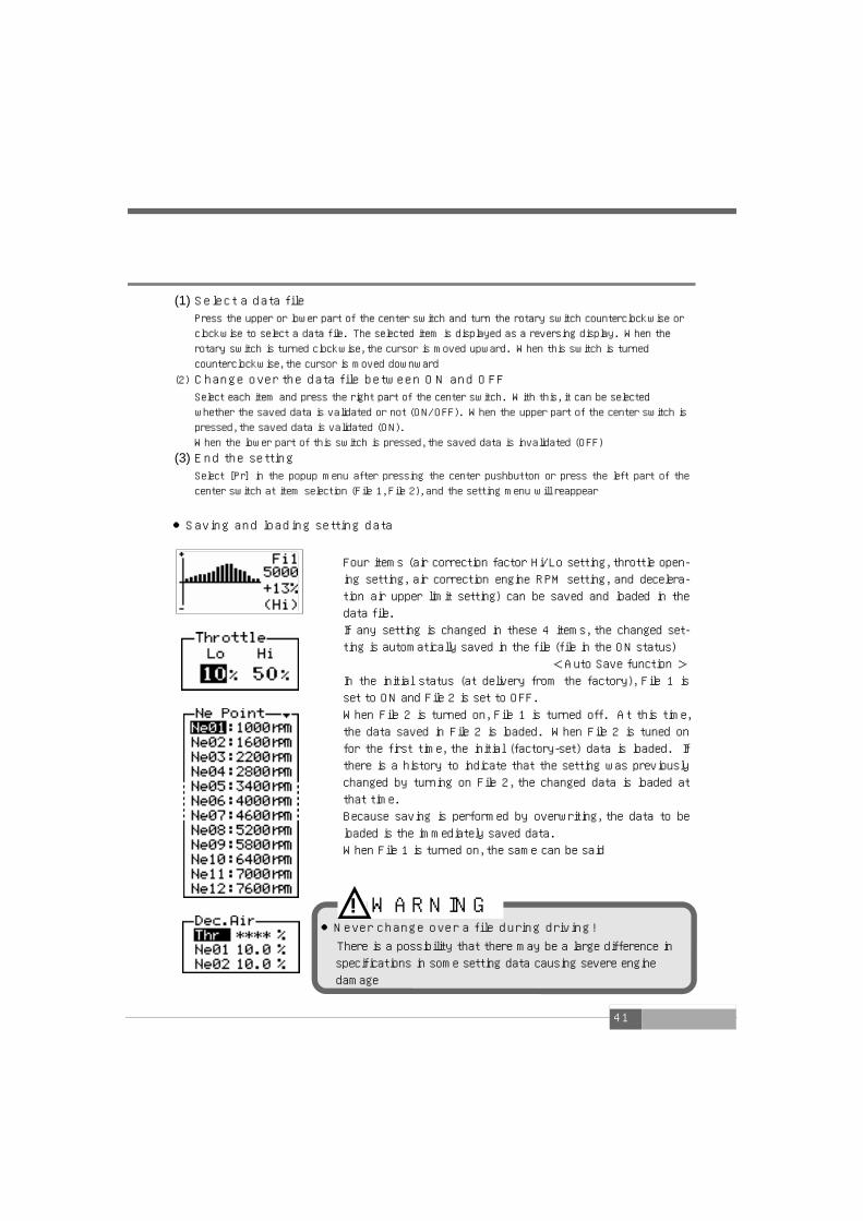
●Saving and loading setting data
Four items (air correction factor Hi/Lo setting, throttle open-
ing setting, air correction engine RPM setting, and decelera-
tion air upper limit setting) can be saved and loaded in the
data file.
If any setting is changed in these 4 items, the changed set-
ting is automatically saved in the file (file in the ON status)
<Auto Save function > In the initial status (at delivery from the factory), File 1 is
set to ON and File 2 is set to OFF.
When File 2 is turned on, File 1 is turned off. At this time,
the data saved in File 2 is loaded. When File 2 is tuned on
for the first time, the initial (factory-set) data is loaded. If
there is a history to indicate that the setting was previously
changed by turning on File 2, the changed data is loaded at
that time.
Because saving is performed by overwriting, the data to be
loaded is the immediately saved data.
When File 1 is turned on, the same can be said
●Never change over a file during driving!
There is a possibility that there may be a large difference in
specifications in some setting data causing severe engine
damage
! WARNING
42
43
Etceteras (etc.) Mode Chapter 6
Sensor type and sensor number setting ______________ 44
Number-of-cylinders and throttle sensor type setting __ 50
Program version check __________________________________________ 59
All data initialization _____________________________________________ 60
What to do in such a case? ____________________________________ 62
44
【etc.】→【Sensor Type】
Sensor type and sensor number setting The sensor type and the sensor number (sensor characteristic) are set according to the vehi
cle. This item is indispensable for initial setup
2. Select [Sensor Type] in the etc. menu 1. Select [etc.] in the main menu
or
Main menu
etc. menu
or
Pr
or Nx
3. The sensor type setting mode is set or Pr
For the sensor types, refer to the Wiring diagram by model on the separate sheet
The sensor number setting varies depending on the selected sensor type
●Hot-Wire or Pressure selection ・・・・・・・P45
●Flap or Karman selection ・・・・・・・・・・・・P49
Sensor selection
(1) Select a sensor type Press the upper or lower part of the center switch and t
urn the rotary switch counterclockwise or clockwise to s
elect a sensor type. The selected item is displayed as a
reversing display. When the rotary switch is turned cloc
kwise, the cursor is moved upward. When this switch is
turned counterclockwise, the cursor is moved downward
(2) Go to the sensor number setting screen Select [Nx] in the popup menu after pressing the center
pushbutton or press the right part of the center switch,
and the sensor number setting screen will appear
(3) End the setting Select [Pr] in the popup menu after pressing the center
pushbutton or press the left part of the center switch, a
nd the etc. menu will reappear
Select
Decide
Go back Select
Select
Go back
or
Select
45
●When the sensor type is set to Hot-Wire or Pressure
■Depending on the car specifications, the In setting and the Out setting must be changed even if the car model is the same
(Example ) Silvia S14 SR20DET 93.10~98.12
※When the ECU is Normal and the airflow sensor is for Z32 In 02=Z32 airflow sensor
Out05=S14 normal airflow sensor
※When the ECU has the characteristics of an airflow
sensor for Z32 and the airflow sensor is for Z32 In 02=Z32 airflow sensor
Out02=Z32 airflow sensor
※When the ECU and the airflow sensor are Normal In 05=S14 normal airflow sensor
Out05=S14 normal airflow sensor
4. Set the sensor number Pr
(1) Select In/Out Operate the left or right part of the center switch to select I
n or Out. The selected numeric value is displayed as a reve
rsing display (2) Set the sensor number
Select a numeric value and press the upper or lower part of
the center switch or turn the rotary switch counterclockwis
e or clockwise to increase or decrease the numeric value When the rotary switch is turned clockwise, the numeric val
ue is increased. When this switch is turned counterclockwis
e, the numeric value is decreased
(3) End the setting Select [Pr] in the popup menu after pressing the center pus
hbutton or press the left part of the center switch at In sele
ction, and the sensor type setting screen will reappear
For the sensor numbers, refer to the Wiring diagram by model on the separate sheet
For ordinary use, set the same sensor number between In and Out
●For Pressure, the setting is completed After the setting of the above (3) is completed, exit from the setting screen. At this tim
e, the set numeric value is saved ●For Hot-Wire, set the sensor output calculation method Select [Nx] in the popup menu after pressing the center pushbutton or press the right
part of the center switch at Out selection, and the sensor output calculation method set-
ting screen will appear
or
Go back
Increase/
decrease
or Select
46
5. Set the sensor output calculation method
(1) Select In or Out Operate the left or right part of the center switch to select
In or Out. The selected numeric value is displayed as a rev
ersing display (2) Set the calculation method
Select a numeric value and press the upper or lower part of
the center switch or turn the rotary switch counterclockwi
se or clockwise to select a calculation method When the rotary switch is turned clockwise, the operation i
s the same as when the upper part of the center switch is
pressed
(3) End the setting Select [Pr] in the popup menu after pressing the center pus
hbutton or press the left part of the center switch at In sel
ection, and the sensor number setting screen will reappear
Calculation method operation diagram
At out
selection
At In selection
※Pressing the upper part of the center switch provides the same function as turning the ro
tary switch clockwise, and pressing the lower part of the center switch provides the sam
e function as turning the rotary counterclockwise
For almost all the models except Skyline GT-R, In 1 and Out 1 are set
For the setting method, refer to the setting examples shown on and after the next page
or Pr
Changeover
or
Go back
Select
At In selection
At out
selection
47
SUPERAIRFLOW CONVERTER
Out
1
※Because of a single engine control unit input
SUPERAIRFLOW CONVERTER
Measured air volume
10
Output air volume
10
Setting the sensor output calculation method (1) ●General vehicles (Usually, this setting is performed.)
When the product is used with an airflow sensor and an ECU with
single airflow sensor control
Input air volume
10
※In this case, the airflow sensor measure
s an air volume of 10
Setting the sensor output calculation method (2) ●Skyline GT-R
When the product is used with two airflow sensors and an
ECU with twin airflow sensor control
※Because of 2 airflow sensors
※Because of 2 engine control unit
inputs, the measured air volume of
the 2 airflow sensors is averaged
(Ave) and its result is output
※In this case, airflow sensor 1 measures
an air volume of 4 and airflow sensor
2 measures an air volume of 6
ECU
ECU
Out
Ave
In
2
In
1
※Because of a single airflow sensor
Airflow
sensor
Measured air volume
4
Measured air volume
6
Airflow
sensor 1
Airflow
sensor 2
Input air volume
10 Output air volume
5
Output air volume
5
48
SUPERAIRFLOW CONVERTER
Out
1/2 In
1
Out
Add
Setting the sensor output calculation method (3) ●General vehicles using 2 airflow sensors
When the product is used with two airflow sensors and an
ECU with single airflow sensor control
In
2
※Because of a single engine control
unit input, the measured air volume
of the 2 airflow sensors is added
(Add) and its result is output
※In this case, airflow sensor 1 measures an air
volume of 4 and airflow sensor 2 measures an
air volume of 6
Setting the sensor output calculation method (4) ●Skyline GT-R using an airflow sensor
When the product is used with an airflow sensor and an
ECU with twin airflow sensor control
ECU
ECU
※Because of 2 airflow sensors
Measured air volume
4
Measured air volume
6
Input air volume
10
Output air volume
10 Airflow
sensor 1
Airflow
sensor 2
※Because of a single airflow sensor
Measured air volume
10
Airflow
sensor
Input air volume
10 Output air volume
5
Output air volume
5
SUPERAIRFLOW CONVERTER
※Because of two engine control unit
inputs, the measured air volume of
the airflow sensor is divided into h
alves and its result is output
※In this case, the airflow
sensor measures an air
volume of 10
49
●When the sensor type is Flap or Karman
※For the sensor numbers, refer to the Wiring diagram by model on the
separate sheet
1. For Flap
2. For Karman
※When Karman is selected, sensor number setting is not required
(1) Select Karman
Press the upper or lower part of the center switch
or turn the rotary switch counterclockwise or cloc
kwise to select Karman. The selected item is displ
ayed as a reversing display. When the rotary swit
ch is turned clockwise, the cursor is moved upwar
d. When this switch is turned counterclockwise, th
e cursor is moved downward (2) End the setting
Select [Pr] in the popup menu after pressing the ce
nter pushbutton or press the left part of the center
switch, and the etc. menu will reappear
or
Increase/decrease
(1) Set the sensor number
Press the upper or lower part of the center
switch or turn the rotary switch counterclock-
wise or clockwise to increase or decrease the
numeric value. When the rotary switch is turned
clockwise, the numeric value is increased. When
this switch is turned counterclockwise, the nu-
meric value is decreased (2) End the setting
Select [Pr] in the popup menu after pressing the
center pushbutton or press the left part of the
center switch at In selection, and the sensor type
setting screen will reappear
or
Select
50
Set the number of cylinders and the throttle type according the vehicle. This item is indispe
nsable for initial setup
2. Select [Car Select] in the etc. menu 1. Select [etc.] in the main menu
Main menu
or
Pr
3. The number-of-cylinders and throttle sensor type
setting mode is set or Pr
(1) Select the number of cylinders
Operate the left or right part of the center switch to
select the number of cylinders. The selected item is d
isplayed as a reversing display (2) Set the number of cylinders
Select an item and press the upper or lower part of t
he center switch or turn the rotary switch counterclo
ckwise or clockwise to increase or decrease the nume
ric value
When the rotary switch is turned clockwise, the nume
ric value is increased. When this switch is turned co
unterclockwise, the numeric value is decreased ※For a rotary car, set “Number of rotors” × 2
※For a Toyota car mounting a V8 engine, set 4
※For Nissan Fairlady Z (Z33), set 1
※For Mazda Atenza (GG#S/P, GY #W), set 2
■Setting range The value in parentheses is the initial value Cyl【cylinders】 1~16 (6) ※ Settable by 1-cylinder steps
etc. menu
or Nx or
【etc.】→【Car Select】 Number-of-cylinders and throttle sensor type setting
Select
Decide
Select
Decide
Go back
Go back
Select or
Select
51
●When No throttle signal (**) is set, correction is not performed by throt
tle opening, so you can set only the Hi mode [Hi-Thrtl] in the air correctio
n factor setting mode. The Lo mode [Lo-Thrtl] cannot be selected. In the
monitor mode, the throttle opening cannot be monitored
NOTE
※Set the throttle sensor type after checking the voltage in the completely
closed/opened status of the throttle in the sensor voltage check mode d
escribed on the next page
(3) Select the throttle sensor type Press the upper or lower part of the center switch or turn the
rotary switch counterclockwise or clockwise to select the throt
tle sensor type (Thr). The selected item is displayed as a rever
sing display (4) Set the throttle sensor type
Select an item and press the upper or lower part of the center
switch or turn the rotary switch counterclockwise or clockwise
to change the direction of the arrow (sensor type). When the r
otary switch is turned clockwise, the operation is the same as
when the upper part of the center switch is pressed. When the
rotary switch is turned counterclockwise, the operation is the s
ame as when the lower part of the center switch is pressed (5) End the setting
Select [Pr] in the popup menu after pressing the center pushbu
tton or press the left part of the center switch at number-of-cy
linders (Cyl) selection, and the etc. menu will reappear
※Pressing the upper part of the center switch provides the
same function as turning the rotary switch clockwise, and
pressing the lower part of the center switch provides the
same function as turning the rotary counterclockwise
When the throttle is completely closed, the throttle sensor voltage is 0 V to 1 V
When the throttle is completely opened, the throttle sensor voltage is 3 V to 5 V
When the throttle is completely closed, the throttle sensor voltage is 3 V to 5 V
When the throttle is completely opened, the throttle sensor voltage is 0 V to 1 V
No throttle signal
Select
52
End the check
Select [Pr] in the popup m
enu after pressing the cent
er pushbutton or press the
left part of the center swit
ch, and the etc. menu will r
eappear
In-1 Airflow sensor voltage 1
Pressure sensor voltage
In-2 Airflow sensor voltage 2
(For a twin airflow car only)
Thrt Throttle sensor voltage
(For a car with a throttle sensor only)
Knk Knocking sensor output value
(For a car with a knocking sensor only)
【etc.】→【Sensor chk】
Sensor check The airflow sensor voltage, pressure sensor voltage, throttle sensor voltage, and knocking
sensor output value are checked.
After wiring, each connection can be checked for normality and each sensor status can be
checked. When setting the throttle sensor type on the previous page, it is necessary to
check the throttle sensor voltage.
Regarding a vehicle provided with multiple knocking sensors, the sensor output value of
each knocking sensor signal is checked and wiring is performed to a sensor signal wire with
the highest output value
2. Select [Sensor Chk] in the etc. menu 1. Select [etc.] in the main menu
Main menu
etc. menu
or
Pr
3. The sensor check mode is set or Pr
or Nx
NOTE ●The knocking sensor output value is raw data including noise that was obtained from
the genuine knocking sensor. Accordingly, a higher numeric value than the actual kno
cking level is displayed. This is not abnormal. (Not a knocking level)
or
Select
Decide
Select
Decide
Go back
Go back
53
(1) Select an item Press the upper or lower part of the center switch and tu
rn the rotary switch counterclockwise or clockwise to sel
ect an item to set a numeric value. The selected item is d
isplayed as a reversing display. When the rotary switch i
s turned clockwise, the cursor is moved upward. When th
is switch is turned counterclockwise, the cursor is moved
downward (2) Set a numeric value
Select a numeric value and press the right part of the center to set the numeric value. Press the upper or lower p
art of the center switch and turn the rotary switch count
erclockwise or clockwise to increase or decrease the num
eric value. When the rotary switch is turned clockwise, t
he numeric number is increased. When this switch is turne
d counterclockwise, the numeric value is decreased ⇒For setting another item Operate the left part of the center switch and repeat step
s (1) and (2)
(3) End the setting Select [Pr] in the popup menu after pressing the center p
ushbutton or press the left part of the center switch at it
em selection, and the etc. menu will reappear
【etc.】→【Disp Scale】
Display scale setting
2. Select [Disp Scale] in the etc. mode 1. Select [etc.] in the main menu
Main menu
or
Pr
3. The display scale setting mode is set or Pr
etc. menu
A graphic display and a analog display in the monitor mode are made and a graph scale in t
he two-dimensional trace mode is set. As a pressure display, one of kg/cm2 and kPa can b
e selected
or Nx
■Setting range The value in parentheses is the initial value Pr:760~0[mmHg]/+1.0,+2.0[kg/c㎡]
0,+100,+200[kPa] (760mmHg)
Ne:6000~10000[rpm] (6000)
Cr:±3,±6,±9,±15,±30[%] (±3)
or
Select
Decide
Select
Decide
Go back
Go back
or
Select
Select
54
When the unit of pressure display is set to pa
scal (kPa) in the display scale setting on the
previous page, the unit of pressure warning in
this item is changed into pascal (kPa)
【etc.】→【Warning Set】
Warning setting
Regarding the airflow using ratio, suction tube pressure, Karman swirl sensor frequency, kn
ocking, or engine revolution speed, the indicator blinks to give a warning to the driver when
the indicated value exceeds the set warning value
2. Select [Warning Set] in the
etc. menu 1. Select [etc.] in the main menu
Main menu
or
or
Pr
Nx
etc. menu
3. The warning setting mode is set or Pr
or
Select
Decide
Select
Decide
Go back
Go back
or
Select Increase/decrease
or
55
(1) Select an item
Press the upper or lower part of the center switch and turn the rotary switch counterclo
ckwise or clockwise to select an item to set a numeric value. The selected item is displ
ayed as a reversing display. When the rotary switch is turned clockwise, the cursor is
moved upward. When this switch is turned counterclockwise, the cursor is moved down
ward (2) Set a numeric value
Select a numeric value and press the right part of the center to set the numeric value.
Press the upper or lower part of the center switch and turn the rotary switch counterclo
ckwise or clockwise to increase or decrease the numeric value. When the rotary switch
is turned clockwise, the numeric number is increased. When this switch is turned counter
clockwise, the numeric value is decreased ⇒For setting another item
Operate the left part of the center switch and repeat steps (1) and (2) (3) End the setting
Select [Pr] in the popup menu after pressing the center pushbutton or press the left par
t of the center switch at item selection (AflW, PrW, KarW, KnkW, RevW), and the etc. m
enu will reappear
■Setting range The value in parentheses is the initial value AflW【Airflow using ratio 】 50~100 OFF (OFF)[%] ※ Settable by 5% steps PrW 【Suction tube pressure 】 -500~2.0 OFF (OFF) [kg/c㎡] ※Settable by 100 mmHg for the negative side
and 0.2 kg/cm2 steps for the positive side -100~200 OFF (OFF) [kPa] ※Settable by 20 kPa steps
KarW【Karman swirl sensor frequency 】 200~1600 OFF (OFF)[Hz] ※Settable by 100 Hz steps
KnkW【Knocking 】 10~200 OFF (OFF) ※Settable by 20 steps RevW【Engine revolution speed 】 3000~9000 OFF (OFF)[rpm] ※Settable by 500 rpm steps
Monitor mode
When the warning value for the
engine revolution speed is set to
5000 rpm
A reversing/blinking display
is repeated
When exceeding the set
warning value ・・・
56
【etc.】→【Pass Lock】
Password setting and change
When a password is optionally set, this can prevent setup data or setting data from being
changed by misoperation or mischief
2. Select [Pass Lock] in the etc. menu 1. Select [etc.] in the main menu
Main menu
or
or
Pr
Nx
3. The password setting/change mode is set or Pr
etc. menu
(1) Select an item
Press the upper or lower part of the center switch and
turn the rotary switch counterclockwise or clockwise t
o select an item. The selected item is displayed as a r
eversing display. When the rotary switch is turned clo
ckwise, the cursor is moved upward. When this switc
h is turned counterclockwise, the cursor is moved dow
nward (2) Set or change a password
Select [Nx] in the popup menu after selecting an item
and pressing the center pushbutton, or press the right
part of the center switch to go to the password input
screen (3) End the setting
Select [Pr] in the popup menu after pressing the cente
r pushbutton or press the left part of the center switc
h, and the etc. menu will reappear NOTE
●Take a note of the set password lest you should forget it ●Avoid setting an easy-to-remember password such as 1111 and AAAA
or
Select
Decide
Select
Decide
Go back
Go back
or
Select
57
(1) Input the password Turn the rotary switch counterclockwise or clockwise and input a password. For
the password, select characters from 0 to 9 and A to Z. Operate the left or right
part of the center switch to shift a digit. (In the initial status, the password is 0000.)
After inputting the password, press the center pushbutton and select [Nx] in the popup
menu. To abort it, select [Pr] or [Tp] in the popup menu to exit from the mode (2) Lock the setup/setting
Press the right part of the center switch, select [Yes], and press the center pushbutton.
If you do not lock the setup/setting, select [No] and press the center pushbutton
●When selecting Lock Mode
Nx
●When selecting Change Pass
(1) Input the password Input the current password by performing the same procedure as that for Lock Mode.
(In the initial status, the password is 0000.) After inputting the password, press the
center pushbutton and select [Nx] in the popup menu. To abort it, select [Pr] or [Tp] in
the popup menu to exit from the mode (2) Input a new password
Input the new password by performing the same procedure as before. After inputting the password, press the center pushbutton
◆Items for which a setting change is prohibited by Password Lock
If an attempt to change any item shown above is made in
the Password Lock status, a warning screen appears
※If a password is wrongly input on the Ent Password screen, the warning screen shown at right appears. Input a correct pass-word again
Nx
Decide
Decide
58
(1) Select an item
Press the left or right part of the center switch to
select an item to set a numeric value. The selected
item is displayed as a reversing display (2) Set a numeric value
Select a numeric value and press the upper or lower
part of the center switch or turn the rotary switch
counterclockwise or clockwise to increase or de-
crease the numeric value. As the numeric value is
increased, it becomes brighter. As the numeric value
is decreased, it becomes darker. When the rotary
switch is turned clockwise, the numeric number is
increased. When this switch is turned counterclock-
wise, the numeric value is decreased (3) End the setting
Select [Pr] in the popup menu after pressing the
center pushbutton or press the left part of the center
switch at [Day] or press the left part of the center
switch at [Nig], and the etc. menu will reappear
In this product, the VFD brightness is automatically adjusted according to the outside lightness by using a built-in optical sensor. It is supposed that the item [Day] is for the brightness of the daytime (bright time), [Dim] is for the brightness of the evening time (dim time), and [Nig] is for the brightness of the nighttime (dark time) Make an adjustment, for example, when the light is dazzling at night. Usually, any change is not required
3. The VFD brightness adjustment mode is set or Pr
etc. menu
or
or
Pr
Nx
2. Select [VFD Bright] in the etc. menu 1. Select [etc.] in the main menu
Main menu
【etc.】→【VFD Bright】
VFD brightness adjustment
or
Select
Decide
Select
Decide
Go back
Go back
Select
Increase/decrease
or
59
【etc.】→【Program Ver.】
Program version check
2. Select [Program Ver] in the
etc. menu 1. Select [etc.] in the main menu
Main menu
or
Pr
etc. menu
or Nx
3. The program version check mode is set
End the check
Select [Pr] in the popup menu after pressing the center pushbutton or press the left part of the center switch, and the etc. menu will reappear
●The program version information is displayed
or Pr
or
Select
Decide
Go back Select
Decide
Go back
60
【etc.】→【Initialize】
All data initialization
Initialize all data to return it to the data status provided at delivery from the factory
⇒Initialize all data
In the all data initialization mode, operate the right part of the
center switch, select [Yes], and press the center pushbutton.
After that, turn off the ignition switch
⇒Exit from the mode without initialization
In the all data initialization mode, perform one of the following operations ・Select [No] and press the center pushbutton ・When [No] has been selected, operate the left part of the cen-
ter switch ・When [Yes] has been selected, operate the right part of the
center switch Then, the etc. menu will reappear
3. The all data initialization mode is set
etc. menu
2. Select [Initialize] in the etc. menu 1. Select [etc.] in the main menu
Main menu
or Nx
or Pr
or
Pr
or
Go back
Select
Decide
Select
Decide
Go back
Select
Decide
61
●Memo
62
●Check if the battery is connected
●Check if the vehicle ECU harness is securely
connected to the signal harness
●Check if the signal harness is connected to
the connector of the SAFC main unit cable
Even if the connection is properly made, the power
supply may not be turned on because of a contact
defect. Check the plug and splice caulking portion
once again ●The power supply is turned off because of
vibrations This may be due to a wiring contact defect
Fault related to the
power supply
What to do in such a case ?
The display is not
normal ●Each signal is not displayed (monitored)
Check if the harness connecting position is correct.
Install the harness by referring to the “Wiring dia-
gram by model” attached to this product, taking
special care about the direction of the ECU, and
checking the connector shape and the number of
pins ●The revolution speed display is not normal
・Check if the number of cylinders is correctly is set
・Genuine tachometers have a slight error. Even when
a deviation of 200 to 300 rpm occurs at a high-
speed revolution, this is normal. The numeric value
of this product is a correct revolution speed ●The throttle opening display is not normal
・Check if the throttle sensor type has been set
・Check if the throttle opening has been learned
・For a vehicle without throttle opening signal, the
throttle display cannot be performed ●Throttle opening Hi/Lo cannot be selected
Check if the throttle type is not set to ** If it is
set to ** correction is not made by throttle open-
ing, so the Hi/Lo map cannot be changed over ●The pressure display does not move
・For an airflow car (Hot Wire, Flap or Karman), the
pressure display does not move.
For a pressure sensor type car only, the pressure
display can be monitored
63
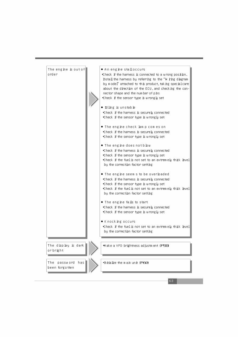
The display is dark
or bright ・Make a VFD brightness adjustment (P58)
The engine is out of
order ●An engine stall occurs
・Check if the harness is connected to a wrong position.
Install the harness by referring to the “Wiring diagram
by model” attached to this product, taking special care
about the direction of the ECU, and checking the con-
nector shape and the number of pins ・Check if the sensor type is wrongly set
●Idling is unstable ・Check if the harness is securely connected
・Check if the sensor type is wrongly set
●The engine check lamp comes on ・Check if the harness is securely connected
・Check if the sensor type is wrongly set
●The engine does not blow
・Check if the harness is securely connected
・Check if the sensor type is wrongly set
・Check if the fuel is not set to an extremely thick level
by the correction factor setting
●The engine seems to be overloaded ・Check if the harness is securely connected
・Check if the sensor type is wrongly set
・Check if the fuel is not set to an extremely thick level
by the correction factor setting
●The engine fails to start
・Check if the harness is securely connected
・Check if the sensor type is wrongly set
●Knocking occurs
・Check if the fuel is not set to an extremely thick level
by the correction factor setting
The password has
been forgotten ・Initialize the main unit (P60)
64
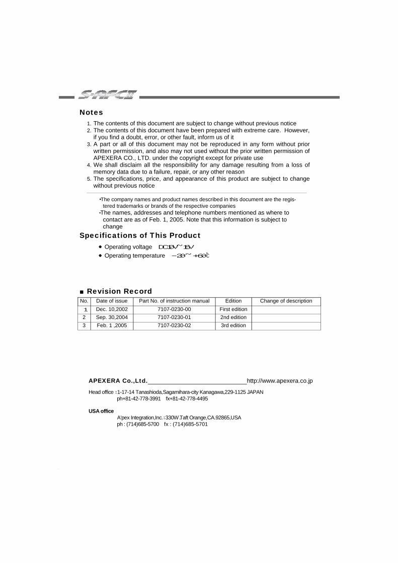
APEXERA Co.,Ltd. http://www.apexera.co.jp
Head office : 1-17-14 Tanashioda,Sagamihara-city Kanagawa,229-1125 JAPAN ph+81-42-778-3991 fx+81-42-778-4495 USA office A’pex Integration,Inc.: 330W.Taft Orange,CA.92865,USA ph : (714)685-5700 fx : (714)685-5701
Notes 1. The contents of this document are subject to change without previous notice 2. The contents of this document have been prepared with extreme care. However,
if you find a doubt, error, or other fault, inform us of it 3. A part or all of this document may not be reproduced in any form without prior
written permission, and also may not used without the prior written permission of APEXERA CO., LTD. under the copyright except for private use
4. We shall disclaim all the responsibility for any damage resulting from a loss of memory data due to a failure, repair, or any other reason
5. The specifications, price, and appearance of this product are subject to change without previous notice
・The company names and product names described in this document are the regis-
tered trademarks or brands of the respective companies ・The names, addresses and telephone numbers mentioned as where to
contact are as of Feb. 1, 2005. Note that this information is subject to change
Specifications of This Product ●Operating voltage DC10V~16V ●Operating temperature -20 ~ +60 ℃
■Revision Record No. Date of issue Part No. of instruction manual Edition Change of description 1 Dec. 10,2002 7107-0230-00 First edition