46
DRAFT - 02 April 2015 GECMA RT Remote Terminals for Hazardous Areas - Zone 1/2 (Gas) April 2015 INM GECMA RT Rev 1 Instruction Manual MTL HMI and Visualisation

DRAFT - 02 April 2015
GECMA RTRemote Terminals for Hazardous Areas -Zone 1/2 (Gas)
April 2015INM GECMA RT Rev 1
Instruction ManualMTL HMI and Visualisation
DRAFT - 02 April 2015 DRAFT - 02 April 2015
INM GECMA RT Rev 1ii
Foreword
Please read the entire operating instructions before starting the assembly, connection, installation and commissioning.
The GECMA Remote Terminal (RT) 22 and associated safe area units must be installed or uninstalled by qualified personnel only. This individual must be qualified to perform the installation of electrical equipment for use in potentially explosive atmospheres, and in accordance to the relevant rules and regulations pursuant to the classification of zones under IEC 60079-14.
The information in the IECEx or EC-type examination certificate should be fully adhered to.
If you have any questions or require technical support, please contact:
Eaton’s Crouse Hinds Business
GECMA Components electronic GmbH Heinrich-Hertz-Strasse 12 50170 Kerpen, Germany
Tel: +49 2273 9812 0 Fax: +49 2273 9812 100 [email protected] www.gecma.com
Technical Developments
The given data is only intended as a product description and should not be regarded as a legal warranty of properties or guarantee. In the interest of further technical developments, we reserve the right to make design changes.
Trademarks used
IBM is a registered trademark of International Business Machines Corporation.
Microsoft and Windows are registered trademarks of Microsoft Corporation.
All other trademarks mentioned and shown in the text are trademarks of the respective owners and are recognised as protected.
© 2015 by GECMA Components electronic GmbH
Rev 1

DRAFT - 02 April 2015 DRAFT - 02 April 2015
INM GECMA RT Rev 1 iii
CONTENTS
1 General Reference . . . . . . . . . . . . . . . . . . . . . . . . . . . . . . . . . . . . . . . . . . . . . . . . . . . . . . . . . . . . . . . . . . 11.1 General Safety Information . . . . . . . . . . . . . . . . . . . . . . . . . . . . . . . . . . . . . . . . . . . . . . . . . . . . . . . . . . . . . . . .1
1.2 Provisions for General Operational Safety . . . . . . . . . . . . . . . . . . . . . . . . . . . . . . . . . . . . . . . . . . . . . . . . . . .2
1.3 Application . . . . . . . . . . . . . . . . . . . . . . . . . . . . . . . . . . . . . . . . . . . . . . . . . . . . . . . . . . . . . . . . . . . . . . . . . . . . .2
1.4 Safety Guidelines . . . . . . . . . . . . . . . . . . . . . . . . . . . . . . . . . . . . . . . . . . . . . . . . . . . . . . . . . . . . . . . . . . . . . . . .2
1.5 Errors and Overloading . . . . . . . . . . . . . . . . . . . . . . . . . . . . . . . . . . . . . . . . . . . . . . . . . . . . . . . . . . . . . . . . . . .2
1.6 Safety Provisions . . . . . . . . . . . . . . . . . . . . . . . . . . . . . . . . . . . . . . . . . . . . . . . . . . . . . . . . . . . . . . . . . . . . . . 3-4
2 Overview . . . . . . . . . . . . . . . . . . . . . . . . . . . . . . . . . . . . . . . . . . . . . . . . . . . . . . . . . . . . . . . . . . . . . . . . . . 52.1 Operating Principle . . . . . . . . . . . . . . . . . . . . . . . . . . . . . . . . . . . . . . . . . . . . . . . . . . . . . . . . . . . . . . . . . . . . . 5-6
2.2 Overview of GECMA RT 22 . . . . . . . . . . . . . . . . . . . . . . . . . . . . . . . . . . . . . . . . . . . . . . . . . . . . . . . . . . . . . . . .7
2.3 Areas of Application . . . . . . . . . . . . . . . . . . . . . . . . . . . . . . . . . . . . . . . . . . . . . . . . . . . . . . . . . . . . . . . . . . . . . .8
2.4 GECMA RT Components in Detail . . . . . . . . . . . . . . . . . . . . . . . . . . . . . . . . . . . . . . . . . . . . . . . . . . . . . . . . . . .8
2.5 Dimensions . . . . . . . . . . . . . . . . . . . . . . . . . . . . . . . . . . . . . . . . . . . . . . . . . . . . . . . . . . . . . . . . . . . . . . . . . . . . .8
3 GECMA RT 22 Display Module . . . . . . . . . . . . . . . . . . . . . . . . . . . . . . . . . . . . . . . . . . . . . . . . . . . . . . . . 93.1 Technical Data . . . . . . . . . . . . . . . . . . . . . . . . . . . . . . . . . . . . . . . . . . . . . . . . . . . . . . . . . . . . . . . . . . . . . . . . . . .9
4 GECMA RT Keyboard . . . . . . . . . . . . . . . . . . . . . . . . . . . . . . . . . . . . . . . . . . . . . . . . . . . . . . . . . . . . . . 104.1 Technical Data . . . . . . . . . . . . . . . . . . . . . . . . . . . . . . . . . . . . . . . . . . . . . . . . . . . . . . . . . . . . . . . . . . . . . . . . . .10
5 GECMA RT Pointing Devices . . . . . . . . . . . . . . . . . . . . . . . . . . . . . . . . . . . . . . . . . . . . . . . . . . . . . . . . 115.1 GECMA RT M Mouse Module . . . . . . . . . . . . . . . . . . . . . . . . . . . . . . . . . . . . . . . . . . . . . . . . . . . . . . . . . . . . .11
5.2 GECMA RT TB Trackball Module . . . . . . . . . . . . . . . . . . . . . . . . . . . . . . . . . . . . . . . . . . . . . . . . . . . . . . . . . . .11
5.3 GECMA RT TP Touchpad Module . . . . . . . . . . . . . . . . . . . . . . . . . . . . . . . . . . . . . . . . . . . . . . . . . . . . . . . . . .11
5.4 GECMA RT J Joystick Module. . . . . . . . . . . . . . . . . . . . . . . . . . . . . . . . . . . . . . . . . . . . . . . . . . . . . . . . . . . . .11
5.5 Technical Data . . . . . . . . . . . . . . . . . . . . . . . . . . . . . . . . . . . . . . . . . . . . . . . . . . . . . . . . . . . . . . . . . . . . . . . . . .12
6 Sytem set-up . . . . . . . . . . . . . . . . . . . . . . . . . . . . . . . . . . . . . . . . . . . . . . . . . . . . . . . . . . . . . . . . . . . . . 136.1 General Information . . . . . . . . . . . . . . . . . . . . . . . . . . . . . . . . . . . . . . . . . . . . . . . . . . . . . . . . . . . . . . . . . . . . .14
6.2 Assembly of the GECMA RT Housing . . . . . . . . . . . . . . . . . . . . . . . . . . . . . . . . . . . . . . . . . . . . . . . . . . . . . .14
6.3 Gecma RT Safe Area Unit . . . . . . . . . . . . . . . . . . . . . . . . . . . . . . . . . . . . . . . . . . . . . . . . . . . . . . . . . . . . . . . .14
6.4 Safe Area Unit Desktop . . . . . . . . . . . . . . . . . . . . . . . . . . . . . . . . . . . . . . . . . . . . . . . . . . . . . . . . . . . . . . . . . .15
6.5 Safe Area Unit Rack . . . . . . . . . . . . . . . . . . . . . . . . . . . . . . . . . . . . . . . . . . . . . . . . . . . . . . . . . . . . . . . . . . 16-17
6.6 Technical Data . . . . . . . . . . . . . . . . . . . . . . . . . . . . . . . . . . . . . . . . . . . . . . . . . . . . . . . . . . . . . . . . . . . . . . . . . .18
7 Power Supply Module AC (Alternating Current) . . . . . . . . . . . . . . . . . . . . . . . . . . . . . . . . . . . . . . . . 197.1 Connecting the AC Power Cable for GECMA RT via the Built-In Power Supply . . . . . . . . . . . . . . . . . . . .19
7.2 Preparing the AC Input Connection . . . . . . . . . . . . . . . . . . . . . . . . . . . . . . . . . . . . . . . . . . . . . . . . . . . . . 19-20
8 Power Supply Module DC (Direct Current) . . . . . . . . . . . . . . . . . . . . . . . . . . . . . . . . . . . . . . . . . . . . . 218.1 Connecting the DC Power Cable for GECMA RT via the Built-In Power Supply . . . . . . . . . . . . . . . . . . . .21
8.2 Preparing the DC Input Connection . . . . . . . . . . . . . . . . . . . . . . . . . . . . . . . . . . . . . . . . . . . . . . . . . . . . . 21-22
8.3 Dimensions of the Auxiliary Power Cable . . . . . . . . . . . . . . . . . . . . . . . . . . . . . . . . . . . . . . . . . . . . . . . . . . .23 continued on following page

DRAFT - 02 April 2015 DRAFT - 02 April 2015
INM GECMA RT Rev 1iv
9 COM Module RT . . . . . . . . . . . . . . . . . . . . . . . . . . . . . . . . . . . . . . . . . . . . . . . . . . . . . . . . . . . . . . . . . . . 249.1 Connections to the COM Module . . . . . . . . . . . . . . . . . . . . . . . . . . . . . . . . . . . . . . . . . . . . . . . . . . . . . . . . . .24
9.2 Connecting the Data Cable . . . . . . . . . . . . . . . . . . . . . . . . . . . . . . . . . . . . . . . . . . . . . . . . . . . . . . . . . . . . . . .25
10 Power Up . . . . . . . . . . . . . . . . . . . . . . . . . . . . . . . . . . . . . . . . . . . . . . . . . . . . . . . . . . . . . . . . . . . . . . . . 2610.1 Operation and Settings . . . . . . . . . . . . . . . . . . . . . . . . . . . . . . . . . . . . . . . . . . . . . . . . . . . . . . . . . . . . . . . 26-27
11 Maintenance . . . . . . . . . . . . . . . . . . . . . . . . . . . . . . . . . . . . . . . . . . . . . . . . . . . . . . . . . . . . . . . . . . . . . . 28 Appendices . . . . . . . . . . . . . . . . . . . . . . . . . . . . . . . . . . . . . . . . . . . . . . . . . . . . . . . . . . . . . . . . . . . . . . .29
. . . . . . . . . . . . . . . . . . . . . . . . . . . . . . . . . . . . . . . . . . . . . . . . . . . . . . . 29
. . . . . . . . . . . . . . . . . . . . . . . . . . . . . . . . . 30-33
. . . . . . . . . . . . . . . . . . . . . . . . . . . . . . . . . . . . . . . . . . 34
. . . . . . . . . . . . . . . . . . . . . . . . . . . . . . . 35
. . . . . . . . . . . . . . . . . . . . . . . . . . . . . . . . . . . . . . . . . . . . . . . . . 36
. . . . . . . . . . . . . . . . . . . . . . . . . . . . . . . . . . . 37
. . . . . . . . . . . . . . . . . . . . . . . . . . . . . . . . . . . . . . 38
. . . . . . . . . . . . . . . . . . . . . . . . . . . . . . . . . . . . . . . . . . . 39-40
. . . . . . . . . . . . . . . . . . . . . . . . . . . . . . . . . . . . . . . . . . . . . . . . . . . . 41
Appendix A - System Diagram
Appendix B - Assembling the Coupling Unit (Optional)
Appendix C - Installing the Power & Data Cable
Appendix D - Earthing Between the STF or EBF and Housing
Appendix E - GECMA RT 22 Drawings
Appendix F - Desktop Version Safe Area Unit Drawings
Appendix G - Rack Version Safe Area Unit Drawings
Appendix H - EU Declaration of Conformity
Appendix I - Returns (RMA Order)
DRAFT - 02 April 2015 DRAFT - 02 April 2015
INM GECMA RT Rev 1 1
1 GENERAL REFERENCE
1 .1 GENERAL SAFETY INFORMATION
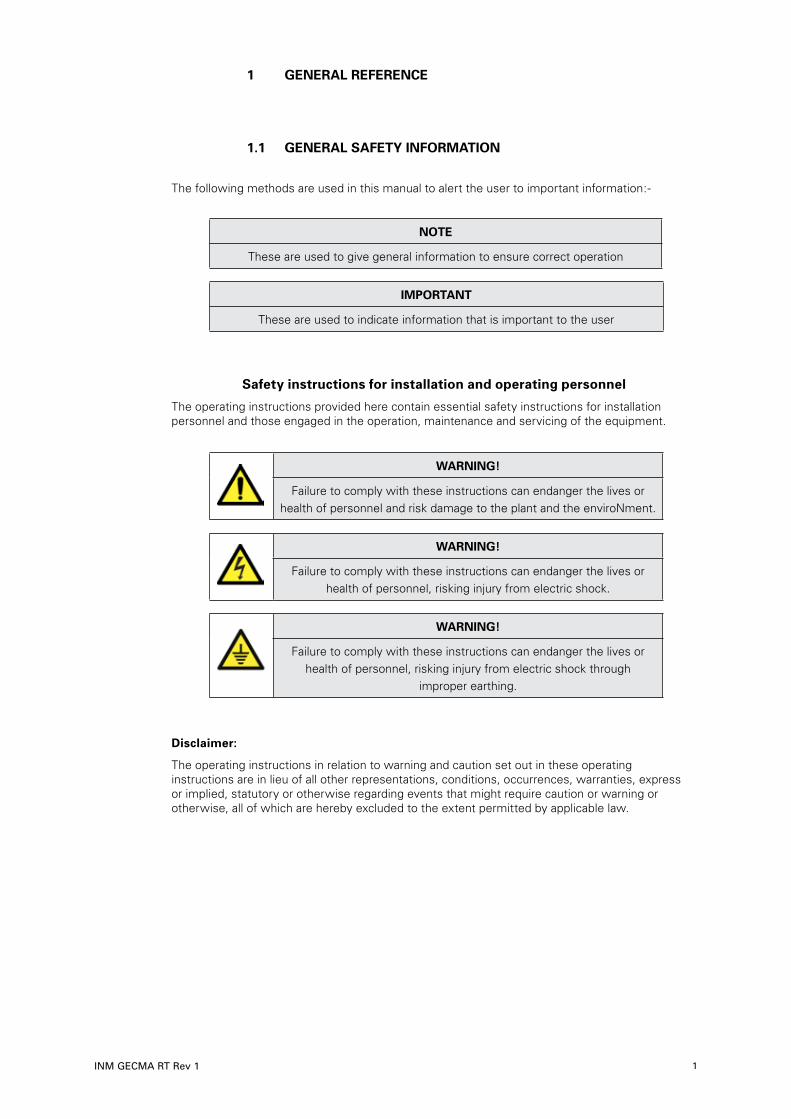
The following methods are used in this manual to alert the user to important information:-
NOTE
These are used to give general information to ensure correct operation
IMPORTANT
These are used to indicate information that is important to the user
Safety instructions for installation and operating personnel
The operating instructions provided here contain essential safety instructions for installation personnel and those engaged in the operation, maintenance and servicing of the equipment.
WARNING!
Failure to comply with these instructions can endanger the lives or health of personnel and risk damage to the plant and the enviroNment.
WARNING!
Failure to comply with these instructions can endanger the lives or health of personnel, risking injury from electric shock.
WARNING!
Failure to comply with these instructions can endanger the lives or health of personnel, risking injury from electric shock through
improper earthing.
Disclaimer:
The operating instructions in relation to warning and caution set out in these operating instructions are in lieu of all other representations, conditions, occurrences, warranties, express or implied, statutory or otherwise regarding events that might require caution or warning or otherwise, all of which are hereby excluded to the extent permitted by applicable law.
DRAFT - 02 April 2015 DRAFT - 02 April 2015
INM GECMA RT Rev 12
1 .2 Provisions for General Operational Safety
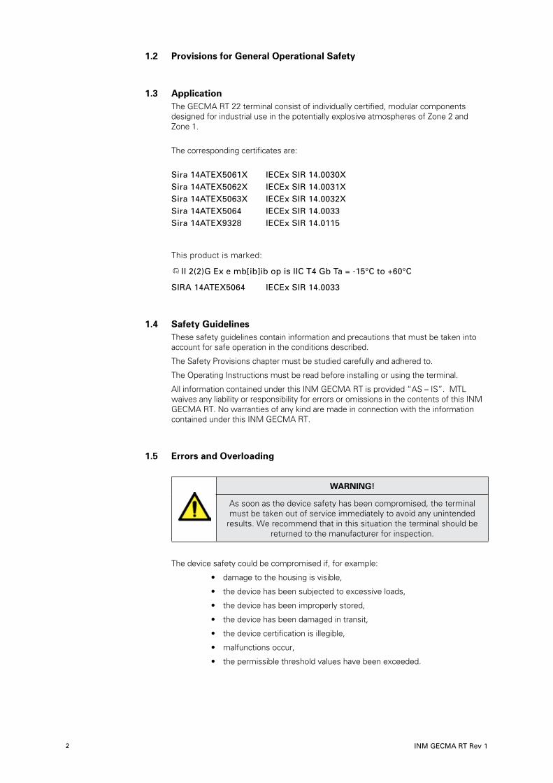
1 .3 ApplicationThe GECMA RT 22 terminal consist of individually certified, modular components designed for industrial use in the potentially explosive atmospheres of Zone 2 and Zone 1.
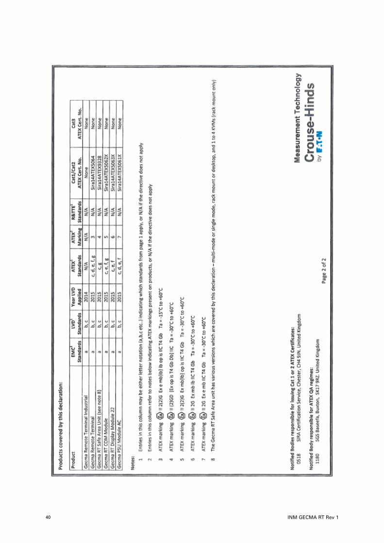
The corresponding certificates are: Sira 14ATEX5061X IECEx SIR 14.0030X Sira 14ATEX5062X IECEx SIR 14.0031X Sira 14ATEX5063X IECEx SIR 14.0032X Sira 14ATEX5064 IECEx SIR 14.0033 Sira 14ATEX9328 IECEx SIR 14.0115
This product is marked:
II 2(2)G Ex e mb[ib]ib op is IIC T4 Gb Ta = -15°C to +60°C
SIRA 14ATEX5064 IECEx SIR 14.0033
1 .4 Safety GuidelinesThese safety guidelines contain information and precautions that must be taken into account for safe operation in the conditions described.
The Safety Provisions chapter must be studied carefully and adhered to.
The Operating Instructions must be read before installing or using the terminal.
All information contained under this INM GECMA RT is provided “AS – IS”. MTL waives any liability or responsibility for errors or omissions in the contents of this INM GECMA RT. No warranties of any kind are made in connection with the information contained under this INM GECMA RT.
1 .5 Errors and Overloading
WARNING!
As soon as the device safety has been compromised, the terminal must be taken out of service immediately to avoid any unintended
results. We recommend that in this situation the terminal should be returned to the manufacturer for inspection.
The device safety could be compromised if, for example:
• damage to the housing is visible,
• the device has been subjected to excessive loads,
• the device has been improperly stored,
• the device has been damaged in transit,
• the device certification is illegible,
• malfunctions occur,
• the permissible threshold values have been exceeded.

DRAFT - 02 April 2015 DRAFT - 02 April 2015
INM GECMA RT Rev 1 3
1 .6 Safety Provisions
WARNING!
Use of the device assumes that the user has observed the standard safety provisions in order to prevent incorrect operation of the device.
WARNING!
The responsibility for planning, installation, commissioning, operation and maintenance, particularly with respect to applications in explosion-
hazard areas, lies with the plant operator.
General:
• The national safety and accident prevention regulations apply.
• MANUAL HANDLING – HEAVY LIFT. GECMA Remote Terminal (RT) 22 has an unpackaged weight that can exceed 70kg. Care must be exercised in the manual handling of these items. Two or three persons, or appropriate machinery, is recommended when lifting and positioning these items.
• Incorrect, impermissible use or non-compliance with these operating instructions may invalidate any warranty.
• All other instructions, notes and regulations contained in these operating instructions must be complied with and observed.
• The GECMA RT 22 may be used in Safe Area, Zone 1 and/or 2 applications corresponding to the EX marking.
• All GECMA RT safe area units must be connected directly to the PC. Only components that are recommended by GECMA Components electronic GmbH can be used for KVM ServSwitch applications.
• The device must only be operated in an undamaged condition as damage can nullify the safe operation of the EX protection.
• The IP rating of the outer RT housing applies only when the rear door is closed and latched.
• The maximum permissible altitude for the operation of the system is 2000 metres.
Before commencing installation or commissioning:
• Read and understand the contents of these instructions.
• Ensure that any operating instructions are fully understood by the personnel responsible.
• Use the device only for its intended purpose.
• The installation and commissioning may only be performed by professional personnel who are trained according to the applicable regulations, standards and guidelines.
• All equipment must be installed, connected and operated correctly and in accordance with the applicable assembly and installation regulations, standards and guidelines.
• It must be ensured that the provisions, e.g. EN 60079-14, the IECEx or EC type examination certificate, and other relevant and applicable standards are followed and observed.
• The equipment must be operated in accordance with the electrical parameters and other information prescribed in the operating instructions and IECEx or EC-type examination certificate.
• The recommended ambient operating temperature range for the GECMA RT 22 is -10°C <= Ta <= +50°C, however the ambient certified temperature range is -15°C <= Ta <= +60°C.
• The GECMA RT Safe Area Unit (Desktop) and GECMA RT Safe Area Unit (Rack Version) transmission units must be installed outside the hazardous area.
continued on following page
DRAFT - 02 April 2015 DRAFT - 02 April 2015
INM GECMA RT Rev 14
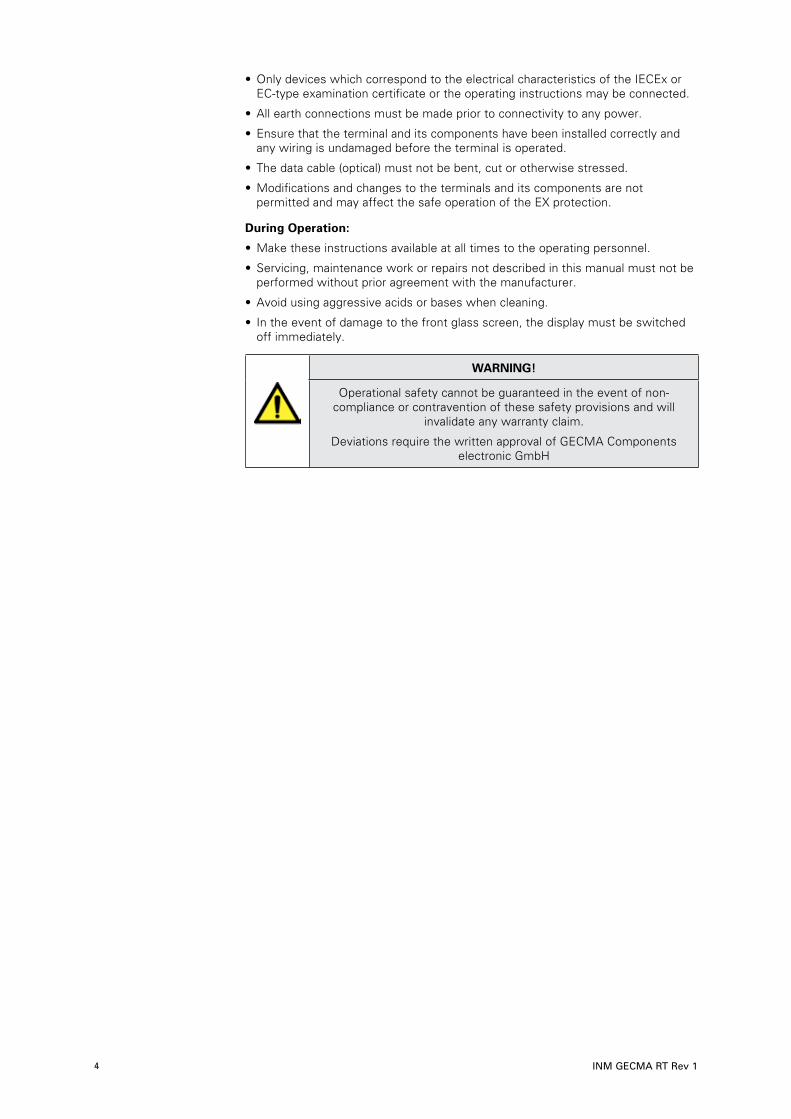
• Only devices which correspond to the electrical characteristics of the IECEx or EC-type examination certificate or the operating instructions may be connected.
• All earth connections must be made prior to connectivity to any power.
• Ensure that the terminal and its components have been installed correctly and any wiring is undamaged before the terminal is operated.
• The data cable (optical) must not be bent, cut or otherwise stressed.
• Modifications and changes to the terminals and its components are not permitted and may affect the safe operation of the EX protection.
During Operation:
• Make these instructions available at all times to the operating personnel.
• Servicing, maintenance work or repairs not described in this manual must not be performed without prior agreement with the manufacturer.
• Avoid using aggressive acids or bases when cleaning.
• In the event of damage to the front glass screen, the display must be switched off immediately.
WARNING!
Operational safety cannot be guaranteed in the event of non-compliance or contravention of these safety provisions and will
invalidate any warranty claim.
Deviations require the written approval of GECMA Components electronic GmbH

DRAFT - 02 April 2015 DRAFT - 02 April 2015
INM GECMA RT Rev 1 5
2 OVERVIEW
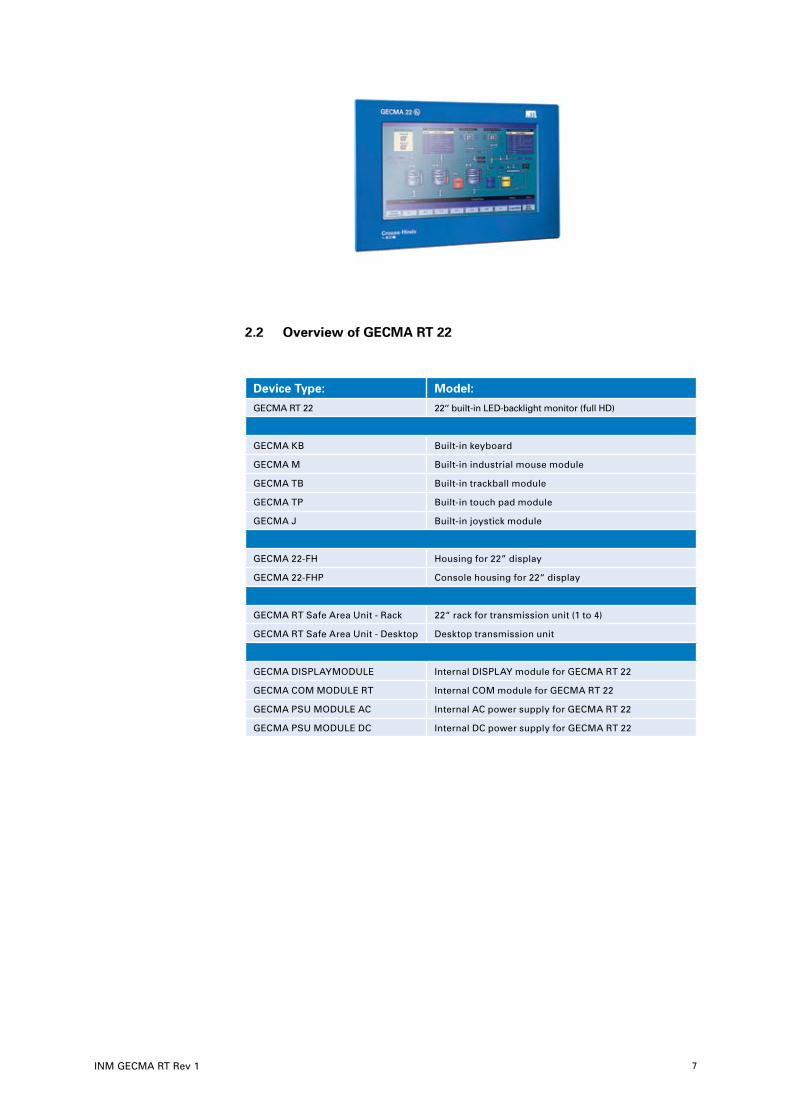
The GECMA RT 22 is a display and control panel for use in hazardous areas. Its modular design consists of a display module, power supply, COMs module, safe area unit and individual peripherals such as; keyboard and pointing device (mouse, trackball, touch pad, joystick).
The safe area unit transmits the PC data in an intrinsically safe manner to the GECMA RT 22 terminal with distances up to 10,000 metres.
The safe area unit is installed outside the hazardous area and connected directly to the PC. DVI graphics for the video signal and USB ports for the keyboard and mouse are then connected directly to the unit. The only system requirement for operation is an IBM-compatible PC. The data-imaging PC requires no system-specific graphics cards or software drivers.
The transfer of the image, keyboard and pointing device data takes place via the safe area unit using a fibre optic cable connected to the GECMA Remote Terminal.
The receiver electronics and ports for keyboard and pointing devices such as mouse/trackball are housed in the GECMA RT housing. The display module and the COM module are supplied by the PSU power supply module.
2 .1 Operating Principle
The video, USB and serial data from the local PC are combined within the safe area unit before being sent via an intrinsically safe connection to the remote display.
Although a special graphics card is not required, we recommend that you use a GFX card that is capable of displaying the native resolution of the hazardous area display module.
The specially designed electronics in the safe area unit and GECMA RT allow for data transmission paths of up to 10,000 m.
GECMA RT Intrinsically Safe display and control panel

DRAFT - 02 April 2015 DRAFT - 02 April 2015
INM GECMA RT Rev 16
The following diagram shows the internal modules of the housing that is located in the hazardous area and illustrates the Ex safety features of the Gecma RT system showing the interconnections and other protective measures.
DRAFT - 02 April 2015 DRAFT - 02 April 2015
INM GECMA RT Rev 1 7
2 .2 Overview of GECMA RT 22
Device Type: Model:
GECMA RT 22 22‘‘ built-in LED-backlight monitor (full HD)
GECMA KB Built-in keyboard
GECMA M Built-in industrial mouse module
GECMA TB Built-in trackball module
GECMA TP Built-in touch pad module
GECMA J Built-in joystick module
GECMA 22-FH Housing for 22” display
GECMA 22-FHP Console housing for 22“ display
GECMA RT Safe Area Unit - Rack 22“ rack for transmission unit (1 to 4)
GECMA RT Safe Area Unit - Desktop Desktop transmission unit
GECMA DISPLAYMODULE Internal DISPLAY module for GECMA RT 22
GECMA COM MODULE RT Internal COM module for GECMA RT 22
GECMA PSU MODULE AC Internal AC power supply for GECMA RT 22
GECMA PSU MODULE DC Internal DC power supply for GECMA RT 22

DRAFT - 02 April 2015 DRAFT - 02 April 2015
INM GECMA RT Rev 18
2 .3 Areas of Application
The GECMA RT 22 can be used wherever operation or visualisation is required indoors or outdoors.
GECMA RT 22:
Software running on any IBM-compatible PC with a full HD resolution of 1920 x 1080 pixels (True Colour 32-bit) can be used.
2 .4 GECMA RT Components in DetailThe GECMA RT has a modular design with the individual components shown in figure below:
Appendix A includes a system diagram showing the interconnection of the individual modules.
2 .5 Dimensions
For system dimensions refer to Appendix E.

DRAFT - 02 April 2015 DRAFT - 02 April 2015
INM GECMA RT Rev 1 9
3 GECMA RT 22 Display Module
IMPORTANT
Do not install the terminal where the display screen will be subjected to direct sunlight. Regular exposure to ultra-violet (UV) rays will reduce the lifetime of
the TFT display panel. Speak to your GECMA representative if you need further guidance on this matter.
3 .1 Technical Data:
Designation GECMA RT 22
Resolution 1920 x 1080 (16 : 9) - lower resolutions are interpolated
Screen Size ca. 22“
Display Type TFT with 16 million colours
Front Panel Anodised aluminium
Certified Ambient Temperature
-15°C <= Ta <= +60°C
Operating Ambient Temperature
-10°C <= Ta <= +50°C

DRAFT - 02 April 2015 DRAFT - 02 April 2015
INM GECMA RT Rev 110
4 GECMA RT Keyboard
The GECMA KB module is a 105-key keyboard which essentially corresponds to the standard Windows keyboard.
4 .1 Technical Data
Designation GECMA RT KB
Keys 105, film-protected short-travel keys
Standard Layout German, English, French
Film Material Technoplast – resistant to most solvents
Certified Ambient Temperature
-15°C <= Ta <= +70°C
Operating Ambient Temperature
-10°C <= Ta <= +50°C

DRAFT - 02 April 2015 DRAFT - 02 April 2015
INM GECMA RT Rev 1 11
5 GECMA RT Pointing Devices
5 .1 GECMA RT M Mouse Module The GECMA RT M is a Microsoft-compatible industrial mouse module and is often used in conjunction with the GECMA RT KB keyboard module.
The 4-stage pressure-sensitive mouse allows precise control of the speed and direction of the cursor.
5 .2 GECMA RT TB Trackball Module The GECMA RT TB is a Microsoft-compatible industry trackball and is often used in conjunction with the GECMA RT KB keyboard module. The 55 mm trackball allows high-precise control of the cursor.
5 .3 GECMA RT TP Touchpad Module The GECMA RT TP is a Microsoft-compatible touchpad and is often used in conjunction with the GECMA RT KB keyboard. The design allows for fast cursor control.
5 .4 GECMA RT J Joystick ModuleThe GECMA RT J is a Microsoft-compatible industrial joystick and is often used in conjunction with the GECMA RT KB keyboard. The design allows for precise cursor control.

DRAFT - 02 April 2015 DRAFT - 02 April 2015
INM GECMA RT Rev 112
5 .5 Technical Data
Designation GECMA RT M GECMA RT TB
GECMA RT TP
GECMA RT TP
Description Industrial mouse with FSR
technology
55 mm trackball Industrial touchpad with resistive touch
film
Industrial joystick
Pushbuttons 2
Front panel Anodised aluminium
Certified Ambient Temperature
-15°C <= Ta <= +70°C
-20°C <= Ta <= +60°C
-40°C <= Ta <= +70°C
-40°C <= Ta <= +70°C
Operating Ambient Temperature
-10°C <= Ta <= +50°C

DRAFT - 02 April 2015 DRAFT - 02 April 2015
INM GECMA RT Rev 1 13
6 System set-up
The following table itemises the weights of individual modules and components to allow a user to assess the weight of an assembled system, either in pedestal housing format (FH) or console mounting (FHP).
GECMA Work Station 22”
Electronics
Display Module 16,0kg
RT Com Module 5,3kg
Power Supply AC Module 3,5kg
Power Supply DC Module 3,0kg
Keyboard 1,9kg
Keyboard-Mouse-Unit 2,0kg
Trackball 0,5kg
Joystick 0,5kg
Mouse 0,5kg
Touchpad 0,5kg
Housing
Display Housing 16,5kg
Keyboard Housing (with struts) 6,1kg
Keyboard Struts (2x) 2,6kg (5,2kg)
Coupling 2,1kg
Pedestal
Pedestal 7,3kg
Elbow 5,2kg
Safe Area Unit
Safe Area Unit Desktop 1,6kg
Safe Area Rack Unit 1 Terminal 4,1kg
Safe Area Rack Unit 2 Terminal 4,4kg
Safe Area Rack Unit 3 Terminal 4,7kg
Safe Area Rack Unit 4 Terminal 5,0kg
Maximum System Weight
FHP Version 22”
Electronics 27,2kg
Housing 29,9kg
Pedestal 7,3kg
Transmission 5,0kg
Total 69,4kg
FH Version 22”
Electronics 24,8kg
Housing 18,6kg
Pedestal 7,3kg
Transmission 5,0kg
Total 55,7kg

DRAFT - 02 April 2015 DRAFT - 02 April 2015
INM GECMA RT Rev 114
6 .1 General Information
IMPORTANT
Do not install the terminal where the display screen will be subjected to direct sunlight. Regular exposure to ultra-violet (UV) rays will reduce the lifetime of
the TFT display panel. Speak to your GECMA representative if you need further guidance on this matter.
WARNING!
The ‘Safety guidelines and provisions’ and ‘Installation and Connection Instructions’ must be studied and strictly adhered to in order to ensure
safe and reliable operation.
WARNING!
The installation may only be carried out by trained specialists who have the appropriate training certification. These personnel must be able to demonstrate familiarity with the specific nature of potentially explosive
atmospheres.
WARNING!
When installing the safe area unit – rack option, adequate space must be ensured for ventilation.
WARNING!
All earthing must be connected or wired prior to commissioning. The connection points are labelled with the
symbol shown here on the right.
6 .2 Assembly of the GECMA RT Housing
The GECMA RT housing is assembled as follows, please refer to the relevant Appendix within this document for further assistance.
1. The standpipe is mounted on the floor using M16 bolts. This work should be performed only by qualified personnel.
2. An assembly coupling (optional) is mounted on the standpipe/elbow – see Appendix B.
3. The power and data cables are fed through the standpipe – see Appendix C.
4. The GECMA RT housing is screwed to the assembly coupling (optional) or the mounting plate – see Appendix B.
5. All remaining earth connections are made.
6 .3 GECMA RT Safe Area Unit
The function of the safe area unit is to combine and transfer optical data through cables to the GECMA RT terminal in the hazardous area.
WARNING!
Warning of injury to eyes: The SFP Transceiver in the ‘Fibre link socket’ operates with a CLASS 1 laser. However, avoid direct and prolonged
contact with the eyes.

DRAFT - 02 April 2015 DRAFT - 02 April 2015
INM GECMA RT Rev 1 15
Two versions of the safe area unit are available:
• Safe Area Unit / Desktop
• Safe Area Unit / Rack (1 – 4 channels)
6 .4 Safe Area Unit / Desktop
The desktop safe area unit, as a single device, connects the controlling PC to the GECMA RT.
The GECMA RT connections can be easily plugged into the safe area unit. This is done via the “FIBRE LINK“ connection.
The connections on the front are as follows:
RS232 IN: for user devices with serial interfaces
DVI / VGA IN: for the video signal feed. DVI-D with optional VGA
DVI / OUT for the video signal transmission e.g. to a local display or another safe area unit (cascading the signal). DVI-D
USB IN USB port for connecting peripherals in the field, e.g. keyboard, trackball etc., to the local PC unit.
FIBRE LINK Fibre-optic connection to the GECMA RT remote terminal. Keyboard, video & mouse (KVM) data, along with USB & serial data is transmitted via the fibre-optic cable to/from the remote terminal allowing the user to interact with the safe-area mounted PC.

DRAFT - 02 April 2015 DRAFT - 02 April 2015
INM GECMA RT Rev 116
The connections on the back are as follows:
Power is supplied via the mains connection socket on the back. An IEC connector cable with 3 x 1.0mm conductors should be used for the AC supply . The fuses are also recessed next to the ON/OFF switch.
6 .5 Safe Area Unit / Rack
The safe area unit is also available in a rack-mount version. This allows up to four remote GECMA RT terminals to be connected to between 1 (cascade) and 4 (point-to-point/direct) PCs located in the safe area.The connections for the fully built rack version are shown in the following figure.
For the sake of clarity, the possible connections are described in only one of the four units. The other three are absolutely identical.
ON/OFFswitch
2 x 2AT fuses Mains connectionsocket (230 VAC)

DRAFT - 02 April 2015 DRAFT - 02 April 2015
INM GECMA RT Rev 1 17
RS232 IN: for user devices with serial interfaces
DVI / VGA IN: for the video signal feed. DVI-D with optional VGA
DVI / OUT for the video signal transmission e.g. to a local display or another safe area unit (cascading the signal). DVI-D
USB IN USB port for connecting peripherals in the field, e.g. keyboard, trackball etc., to the local PC unit..
FIBRE LINK Fibre-optic connection to the GECMA RT remote terminal. Keyboard, video & mouse (KVM) data, along with USB & serial data is transmitted via the fibre-optic cable to/from the remote terminal allowing the user to interact with the safe-area mounted PC.
The connections on the back are as follows:
Power is supplied via the mains connection socket on the back. An IEC connector cable with 3 x 1.0mm conductors should be used for the AC supply . The fuses are also recessed next to the ON/OFF switch.
WARNING!
All groundings must be connected or wired prior to commissioning. The connection points are labelled with the
symbol shown here on the right.
ON/OFFswitch
2 x 2AT fuses Mains connectionsocket (230 VAC)
GND earthing bolt

DRAFT - 02 April 2015 DRAFT - 02 April 2015
INM GECMA RT Rev 118
6 .6 Technical Data
Designation GECMA RT Safe Area Unit /Desktop
GECMA RT Safe Area Unit/ Rack
Housing Desktop housing 19”-plug-in 3 HE, 14 TE
Power Supply 100 - 240 V AC
Power Input 6 W 25 W (with 4 outputs)
Connections DVI/VGA IN, DVI OUT, RS232 IN, USB IN, FIBRE
LINK
4 x (DVI/VGA IN, DVI OUT, RS232 IN, USB IN, FIBRE
LINK)
Fuses 2 x 2AT
Dimensions mm (WxH xD) 203 x 52 x191 430 x 44 x 220
Total: 483 x 44 x 264
Weight 1.6 kg 5.0 kg
Certified Ambient Temperature
-15 °C <= Ta <= +60 °C
Operating Ambient Temperature
0 °C <= Ta <= +40 °C

DRAFT - 02 April 2015 DRAFT - 02 April 2015
INM GECMA RT Rev 1 19
7 Power Supply Module AC (Alternating Current)
Important Information Concerning Connection
WARNING!
The installation may only be carried out by individuals who have the appropriate training. These personnel must be able to demonstrate familiarity with the specific nature of operationally reliable systems.
WARNING!
The Remote Terminal must be installed with a disconnecting switch close to it, within easy reach of the operator and compliant with the relevant parts of IEC 60947-1 and IEC 60947-3. It must be marked to show this function and show ON and OFF positions. Wiring should
conform to local codes. European regulations recommend that fuses be fitted in both the live
and neutral of the mains supply to the instrument.
The isolating switch located beside the equipment MUST be fused at 3.15A.
7 .1 Connecting the AC Power Cable for GECMA RT via the Built-In Power SupplyThe modules inside the GECMA RT housings are pre-wired and interconnected at the factory. During installation on site, only the incoming power, protective ground (earthing) and data connections are required.
7 .2 Preparing the AC input connectionThe back of the housing must be opened to allow connection of the power supply. This can be achieved by rotating the four latches on the rear of the housing using the key provided.
The power cables are fed through the M25 cable gland of the standpipe/elbow and connected directly to the power supply.
The GECMA COM module RT is mounted to the right and the GECMA PSU power supply module is mounted on the left as shown in the above diagram.

DRAFT - 02 April 2015 DRAFT - 02 April 2015
INM GECMA RT Rev 120
The power supply cover is secured using four screws. These screws must be removed to allow access for the mains connection. When replacing the power supply cover the four screws should be tightened to a maximum torque setting of 2 Nm.
Inside there are two connection terminals.
The right terminal block is pre-wired and no modifications are permitted.
The left terminal block connections should be made in accordance with the diagram shown below. The cable is fed through the left cable gland (M25) of the power supply and connected accordingly.
NOTE
The cable terminal can be unlocked using a suitable screwdriver and the connecting cable can be inserted.
After the power connections have been made, the cover should be replaced securely using the four screws provided. The AC power
installation is then complete.
Please refer to the ‘Connecting the data cable’ section
A protective-ground cable, with a cross-sectional area of 4mm2 or greater, must be installed between the metalwork of the RT terminal and a suitable low-impedance, site safety, ground point. Both the STF and EBF assemblies are provided with a threaded hole at their base to accept a screw that enables a protective ground wire to be connected. If a custom housing has been specified, that requires no STF or EBF piping, it will be provided with a threaded hole or stud to which the ground wire can be attached. Ring terminals should be installed at each end of this protective-ground cable to provide a simple and secure method of connection.
Unlocking devicefor cable terminal
Ring cable lug for theearthing bolt
Power SupplyModule
COM Module Latches

DRAFT - 02 April 2015 DRAFT - 02 April 2015
INM GECMA RT Rev 1 21
8 Power Supply Module DC (Direct Current)
Important Information Concerning Connection
WARNING!
The installation may only be carried out by individuals who have the appropriate certification. These personnel must be able to demonstrate
familiarity with the specific nature of operationally reliable systems.
WARNING!
The Remote Terminal must be installed with a disconnecting switch close to it, within easy reach of the operator and compliant with the relevant parts of IEC 60947-1 and IEC 60947-3. It must be marked to show this function and show ON and OFF positions. Wiring should
conform to local codes. European regulations recommend that fuses be fitted in both the live
and neutral of the mains supply to the instrument.
The isolating switch located beside the equipment MUST be fused at 6.3A.
8 .1 Connecting the DC Power Cable for GECMA RT via the Built-In Power SupplyThe modules inside the GECMA RT housings are pre-wired and interconnected at the factory. During installation on site, only the incoming power, protective ground (earthing) and data connections are required.
8 .2 Preparing the DC input connectionThe back of the housing must be opened to allow connection of the power supply. This can be achieved by rotating the four latches on the rear of the housing using the key provided.
The power cables are fed through the M25 cable gland of the standpipe/elbow and connected directly to the power supply.
The GECMA COM module RT is mounted to the right and the GECMA PSU power supply module is mounted on the left as shown in the following diagram.

DRAFT - 02 April 2015 DRAFT - 02 April 2015
INM GECMA RT Rev 122
The power supply cover is secured using four screws. These screws must be removed to allow access for the mains connection. When replacing the power supply cover the four screws should be tightened to a maximum torque setting of 2 Nm.
Inside there are two connection terminals.
The right terminal block is pre-wired and no modifications are permitted.
The left terminal block connections should be made in accordance with the
diagram shown below. The cable is fed through the left cable gland (M25) of the power supply and connected accordingly.
NOTE
The cable terminal can be unlocked using a suitable screwdriver and the connecting cable can be inserted.
After the power connections have been made, the cover should be replaced securely using the four screws provided. The DC power
installation is then complete.
Please refer to the ‘Connecting the data cable’ section
A protective-ground cable, with a cross-sectional area of 4mm2 or greater, must be installed between the metalwork of the RT terminal and a suitable low-impedance, site safety, ground point. Both the STF and EBF assemblies are provided with a threaded hole at their base to accept a screw that enables a protective ground wire to be connected. If a custom housing has been specified, that requires no STF or EBF piping, it will be provided with a threaded hole or stud to which the ground wire can be attached.
Ring terminals should be installed at each end of this protective-ground cable to provide a simple and secure method of connection.
Unlocking devicefor cable terminal
Ring cable lug for theearthing bolt
24 V
24 V=
Power SupplyModule
COM Module Latches
DRAFT - 02 April 2015 DRAFT - 02 April 2015
INM GECMA RT Rev 1 23
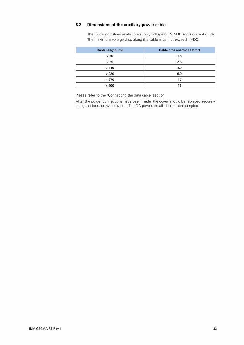
8 .3 Dimensions of the auxiliary power cable
The following values relate to a supply voltage of 24 VDC and a current of 3A. The maximum voltage drop along the cable must not exceed 4 VDC.
Cable length [m] Cable cross-section [mm²]
< 50 1.5
< 85 2.5
< 140 4.0
< 220 6.0
< 370 10
< 600 16
Please refer to the ‘Connecting the data cable’ section.
After the power connections have been made, the cover should be replaced securely using the four screws provided. The DC power installation is then complete.

DRAFT - 02 April 2015 DRAFT - 02 April 2015
INM GECMA RT Rev 124
9 COM Module RT
9 .1 Connections to the COM Module
All of the GECMA RT products specified in Sections 4 & 5 may be connected to the appropriate ports on the rear of the COM unit module. Before connecting any other device to the COM unit ensure that it is compatible with the entity parameters for that port as shown in the following table.
RS232 USB 1 USB 2 USB 3 USB 4 External keyboard port
(KB)
External pointing device port
(PD)
Ui 12 V 0 0 0 0 0 0
Ii - - - - - - -
Pi - - - - - - -
Ci 0 11 nF 11 nF 11 nF 11 nF 0 0
Li 0 0 0 0 0 0 0
Uo 6.015 V 5.355 V 5.355 V 5.355 V 5.355 V 5.5 V 5.5 V
Io 26 mA 972 mA 972 mA 972 mA 972 mA 267 mA 126 mA
Po 39 mW 1.676 W 1.676 W 1.676 W 1.676 W 613 mW 264 mW
Co 37 uF 57.9 uF 57.9 uF 57.9 uF 57.9 uF 58 uF 58 uF
Lo 52 mH 37 uH 37 uH 37 uH 37 uH 498 uH 2239 uH
Once the power supply has been connected, all remaining connections
are made to the GECMA COM module RT. These are illustrated in the following diagram:
SW501 reserved
J706 reserved
J302 video signal to the display – already connected
USB1 to 4 USB ports for other devices on the terminal
Fibre Optic data cable connection (fibre optic cable) with latch
KB keyboard connection – already connected
PD connection for pointing device such as mouse/trackball – already connected
RS232 connection for devices with serial interface

DRAFT - 02 April 2015 DRAFT - 02 April 2015
INM GECMA RT Rev 1 25
9 .2 Connecting the Data Cable
The data cable is a fibre optic cable with optical transmission (FOC). The advantage of using this is fast loss-free data transmission over long distances.
The sensitivity of the cable is to be regarded as a disadvantage. It is essential to make sure that the cable is handled and laid with great care and without sharp kinks.
The fibre optic cable uses LC connectors on both sides:
The data cable is carefully fed through the M20 cable gland in the base, screwed and connected to the display (COM module).
The fibre optic data cable is inserted into the COM module at the position shown below and should be locked in place.
WARNING!
Warning of injury to eyes: The SFP Transceiver in the ‘Fibre link socket’ operates with a CLASS 1 laser. However, avoid direct and prolonged
contact with the eyes.
Data CableConnection
COM Module

DRAFT - 02 April 2015 DRAFT - 02 April 2015
INM GECMA RT Rev 126
10 Power Up
Before switching on the system, check again to make sure everything is mounted, connected and installed as prescribed so as to ensure safe operation of the terminal.
We recommend that all types of power management in the PC are deactivated.
The power is controlled by the local power switch (no power switch on the terminal)
10 .1 Operation and Settings
Upon successful installation of all components the image of the controlling PC shall appear on the GECMA RT display. All functions are available on the terminal.
If the data connection is interrupted or unavailable, the GECMA terminal will signal this immediately.
• With an onscreen message referring to an interrupted data connection (Fibre Link to PC fail)
• A bright, red, visable alarm indicator will flash around the border of the display and will contain the most recent displayed image.
NOTE
This mode of operation where a red border is displayed upon loss of signal can be enabled via the onscreen menu.
• This menu can be accessed by pressing the ‘Scroll Lock’ key five times.

DRAFT - 02 April 2015 DRAFT - 02 April 2015
INM GECMA RT Rev 1 27
On-screen menu:
To enable the ‘Show last image enabled’ feature select ‘S’. The option can be changed by pressing ‘S’ again.
Key 1 for display option on Key 0 for display option off
To exit the on-screen menu press ‘Q’.
NOTE
The corresponding firmware version is visible on this on-screen menu.
IMPORTANT
We should point out that indiscriminate adjustment of the other options may lead to malfunctions.

DRAFT - 02 April 2015 DRAFT - 02 April 2015
INM GECMA RT Rev 128
11 MAINTENANCE
At regular intervals, depending upon the particular location of the RT terminal, the general state of the terminal should be assessed for both its electrical and mechanical condition.
The following item checks should be considered for inspection.
1. Check for any signs of wear, tampering, or impact damage to the RT housing and its display. The terminal must be taken out of use immediately if the damage is judged to be affecting the Ex protection of the equipment.
2. Check all ground (earth) connections for integrity and condition. Check for any signs of corrosion at terminals, and that all screw connections are adequately tightened.
3. Check power connections and the state of the cables carrying the power. If there are signs of wear or cable damage the equipment must be taken out of service immediately and not restored to use until any damaged cables have been replaced.
4. When possible, taking appropriate precautions regarding access, check for the correct value of the fuse ratings in the isolating switch enclosure.
5. Check the tightness of all mechanical fastenings, especially those supporting the terminal housing and its connecting bolts to a standpipe (STF) or elbow (EBF).
6. Check for the presence or build-up of dust, dirt or contaminants on the housing and its components and deal with any accumulations appropriately.
7. Check for any other maintenance issues that may be dictated by site rules.
8. Avoid using aggresive acids or bases when cleaning.

DRAFT - 02 April 2015 DRAFT - 02 April 2015
INM GECMA RT Rev 1 29
Appendices
Appendix A - System Diagram
All connections are made at the factory. Only the respective power supply cable and the data cable (fibre optic cable) are to be connected to the safe area unit on-site.
�fl���
��
fifl��
Com
ms
asse
mbl
y
Dis
play
Com
ms
Pow
er C
able
Inpu
t Cab
leI.S
. USB
con
nect
ion
��
To p
oint
ing
Fibr
e op
tic
(PS/
2)To
key
boar
d
to S
afe
Area
devi
ce
Dis
play
ass
embl
y
������
������
NL
��
��
22V fused
22V out
22V out
5V in0V
22V fused
(PS/
2)
CO
N7
5V out
0V
scre
en
To
Dis
play
Pow
er C
able
for o
ptio
nal t
ouch
-
Com
ms
LVD
SC
able
B FD
GEC
MA
RT
SYST
EM D
IAG
RAM
A.0
9.14
Tole
ranc
e ±
Iss.
Solid
Wor
ksA3
Luto
n, E
ngla
ndM
easu
rem
ent T
echn
olog
y Lt
d,
Title
FEDCBA
Shou
ld B
e O
btai
ned
Writ
ten
Perm
issi
on T
o C
opy
Cop
yrig
ht R
eser
ved
Scal
e 1
:1D
rg. N
o
Third
Ang
le P
roje
ctio
n
D
o N
ot S
cale
D
imen
sion
s in
mm
A.0
Shee
t 1
of
1
CI6
815-
626
Dat
e
12
87
65
43 3
46
72
15
8
Mod
ifica
tion
Iss
EA C
N/A
SW50
1Vi
deo
fifl��
fifl��
fifl��
��
Opt
iona
l
Pow
er
AC: 1
00-2
30V
acD
C: 1
8-36
Vdc
To
CO
N6
CO
N4

DRAFT - 02 April 2015 DRAFT - 02 April 2015
INM GECMA RT Rev 130
Appendix B - Assembling the Coupling Unit (Optional)
The coupling is the connection element between the stand- or mounting pipe and the terminal. This allows the terminal to be rotated for optimal use.
• First, the two Allen screws are to be unscrewed in order to remove the casing from the main coupling element. The screws are replaced later.
• The sealing ring of the casing should be extensively lubricated (use ca. ½ tube of assembly paste).
• The casing is now inverted with the narrow opening over the pipe and pushed so far down that approx. 20 cm of the mounting tube is exposed above.
A
B
CD
E
A - Lubricant Paste. B - x4 (M6 12) socket head screws for housing. C - x3 (M6 16) self-tapping screws. D - Casing E - Main coupling element

DRAFT - 02 April 2015 DRAFT - 02 April 2015
INM GECMA RT Rev 1 31
• The main coupling element is placed on the end of the pipe.
The 3 bore holes are overlaid with the drill openings of the pipe by rotating the main coupling element.
Important: Pay attention to the orientation of the notch in the casing. This should be opposite the groove on the coupling element, i.e. about 180°. Only then is a maximum turning radius for the terminal guaranteed.
• The main coupling element is connected to the pipe end by tightening the three self-tapping Allen screws to a maximum torque seting of 9 Nm. The holes must not be drilled in advance
Groove in the casing Groove in the main coupling element
DRAFT - 02 April 2015 DRAFT - 02 April 2015
INM GECMA RT Rev 132
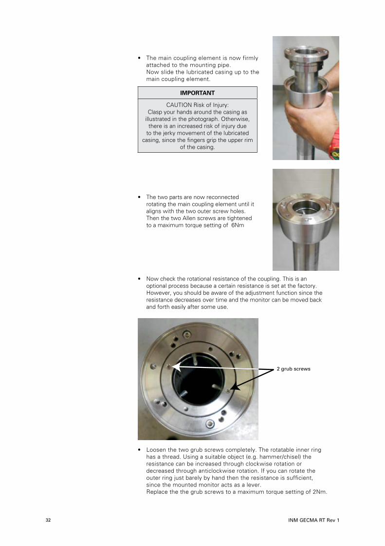
• The main coupling element is now firmly attached to the mounting pipe. Now slide the lubricated casing up to the main coupling element.
IMPORTANT
CAUTION Risk of Injury: Clasp your hands around the casing as
illustrated in the photograph. Otherwise, there is an increased risk of injury due
to the jerky movement of the lubricated casing, since the fingers grip the upper rim
of the casing.
• The two parts are now reconnected rotating the main coupling element until it aligns with the two outer screw holes. Then the two Allen screws are tightened to a maximum torque setting of 6Nm
• Now check the rotational resistance of the coupling. This is an optional process because a certain resistance is set at the factory. However, you should be aware of the adjustment function since the resistance decreases over time and the monitor can be moved back and forth easily after some use.
• Loosen the two grub screws completely. The rotatable inner ring has a thread. Using a suitable object (e.g. hammer/chisel) the resistance can be increased through clockwise rotation or decreased through anticlockwise rotation. If you can rotate the outer ring just barely by hand then the resistance is sufficient, since the mounted monitor acts as a lever. Replace the the grub screws to a maximum torque setting of 2Nm.
2 grub screws

DRAFT - 02 April 2015 DRAFT - 02 April 2015
INM GECMA RT Rev 1 33
• Now attach the seal (O-ring) and apply the remaining half tube of lubricant there.
• Loosely screw in two of the four Allen screws in the areas shown, i.e. with three to four turns.
NOTE
Before mounting the terminal housing, we recommend at this point that the required cables (power supply and data cable) be fed through the standpipe as
described in Appendix C.
• The terminal housing is then ready to be mounted onto the coupling unit. This is achieved by placing the elongated holes on the housing over the screws that have just been fixed to the coupling unit as shown below.
• When the housing is stable and in position, insert the remaining x2 screws and tighten all four screws evenly to a maximum torque setting of 9-10Nm.
• The terminal can now be positioned in place and rotated to the desired angle.
Seal (O-ring)
Loosely screwin the screw
Loosely screwin the screw

DRAFT - 02 April 2015 DRAFT - 02 April 2015
INM GECMA RT Rev 134
Appendix C - Installing the Power & Data Cable Cable gland entry points (M20 & 25) are provided in the standpipe as a method of routing the power and data cables. Remove the glands and feed the cable through the standpipe. The cable glands can then be fastened securely.
NOTE
Please handle the fibre cable with extra care to ensure no breakages occur during installation and ensure that all glands are sealed to IP54.
NOTE
Unused cable gland entry points must be sealed with a suitable Ex approved blanking plug. These can be sourced from GECMA Components electronic
GmbH if required.

DRAFT - 02 April 2015 DRAFT - 02 April 2015
INM GECMA RT Rev 1 35
Appendix D - Earthing Between the STF or EBF and Housing
WARNING!
When using a standpipe (STF) or an elbow (EBF) and a rotatable coupling, the pre-installed earthing cable on the FH/FHP housing must
be connected to one of the self-tapping coupling screws (inside the standpipe) M6x20.
Earthing of the coupling to the housing Earthing on the inside of the STF to a (Similar to image) coupling screw
NOTE
You can also refer to Appendix B for more information.

DRAFT - 02 April 2015 DRAFT - 02 April 2015
INM GECMA RT Rev 136
Appendix E - GECMA RT 22 Drawings
Display housing dimensions
Terminal and standpipe dimensions
SECTION BB

DRAFT - 02 April 2015 DRAFT - 02 April 2015
INM GECMA RT Rev 1 37
Appendix F - Desktop Version Safe Area Unit Drawings
Safe area unit dimensions

DRAFT - 02 April 2015 DRAFT - 02 April 2015
INM GECMA RT Rev 138
Appendix G - Rack Version Safe Area Unit Drawings
Display shows full configuration with four outputs

DRAFT - 02 April 2015 DRAFT - 02 April 2015
INM GECMA RT Rev 1 39
Appendix H - EU Declaration of Conformity
DRAFT - 02 April 2015 DRAFT - 02 April 2015
INM GECMA RT Rev 140

DRAFT - 02 April 2015 DRAFT - 02 April 2015
INM GECMA RT Rev 1 41
Appendix I - Returns (RMA Order)
Dear Customer
Should you find your goods are defective or require a warranty repair, please complete the on-line form on our website at www.gecma.com resources/rma to obtain a RMA reference for the return of your goods
Please note that the processing of your return will take longer if goods are sent back to us without a valid RMA number. An RMA number must be included so that your return can be processed quickly and efficiently.
Please have the following information ready: • Product name and serial number – you may enter multiple answers where there is more than one product
• An error description with as much detail as possible
• Contact information (responsible person(s) and shipping address)
If you have submitted the form, you shall receive two emails:
• A confirmation email (IMPORTANT: Please check your junk mailbox)
• An email with the RMA number to be used (this will be sent to you as soon as possible)
Please make the RMA number clearly visible on the package and also include this on the delivery note.
WARNING!
Please ensure prior to returning defective devices that the goods being sent back were not used in areas harmful to health and were cleaned
according to the applicable provisions of the Occupational Health and Safety Act.
Suitable packaging material can be provided for the return for a surcharge.
Please send the goods, with the RMA number clearly visible on the package, to the following address:
Eaton’s Crouse Hinds Business
GECMA Components electronic GmbH
Heinrich-Hertz-Strasse 12
50170 Kerpen, Germany
If you require further assistance, please use our product support form, which can be found within the resource section at www.gecma.com, alternatively you can call us on:
+49 (0) 2273 – 9812 – 0
+49 (0) 2237 – 9812 - 364
Thank you
Your Customer Service Department Team

DRAFT - 02 April 2015
EUROPE (EMEA): +44 (0)1582 723633 [email protected]
THE AMERICAS: +1 800 835 7075 [email protected]
ASIA-PACIFIC: +65 6 645 9888 [email protected]
The given data is only intended as a product description and should not be regarded as a legal warranty of properties or guarantee. In the interest of further technical developments, we reserve the right to make design changes.
Measurement Technology Limited, Great Marlings, Butterfield, LutonBeds, LU2 8DL, UK.Tel: + 44 (0)1582 723633 Fax: + 44 (0)1582 422283E-mail: [email protected]
© 2015 MTL All Rights ReservedPublication No. INM GECMA RT Rev 1April 2015
AUSTRALIAMTL Instruments Pty Ltd, 205-209 Woodpark Road, Smithfield, New South Wales 2164, AustraliaTel: + 61 1300 308 374 Fax: + 61 1300 308 463
E-mail: [email protected]
BeNeLuxMTL Instruments BVTerheijdenseweg 465, 4825 BK BredaThe Netherlands Tel: + 31 (0) 76 7505360 Fax: +31 (0) 76 7505370
E-mail: [email protected]
CHINACooper Electric (Shanghai) Co. Ltd955 Shengli Road, Heqing Industrial ParkPudong New Area, Shanghai 201201Tel: + 86 2128993817 Fax: + 86 2128993992
E-mail: [email protected]
FRANCEMTL Instruments sarl,7 rue des Rosiéristes, 69410 Champagne au Mont d’OrFranceTel: + 33 (0)4 37 46 16 70 Fax: +33 (0)4 37 46 17 20
E-mail: [email protected]
GERMANYMTL Instruments GmbH, Heinrich-Hertz-Str. 12, 50170 Kerpen, GermanyTel: + 49 (0)22 73 98 12 - 0 Fax: + 49 (0)22 73 98 12 - 2 00
E-mail: [email protected]
INDIAMTL India, No.36, Nehru Street, Off Old Mahabalipuram RoadSholinganallur, Chennai - 600 119, IndiaTel: + 91 (0) 44 24501660 /24501857 Fax: + 91 (0) 44 24501463
E-mail: [email protected]
ITALYMTL Italia srl, Via A. Meucci, 10, I-20094 Corsico (MI), ItalyTel: + 39 (0)2 61802011 Fax: + 39 (0)2 61294560
E-mail: [email protected]
JAPANCooper Crouse-Hinds Japan KK, MT Building 3F, 2-7-5 Shiba Daimon, Minato-ku,Tokyo, Japan 105-0012Tel: + 81 (0)3 6430 3128 Fax: + 81 (0)3 6430 3129
E-mail: [email protected]
NORWAYNorex ASFekjan 7c, Postboks 147, N-1378 Nesbru, Norway Tel: + 47 66 77 43 80 Fax: + 47 66 84 55 33
E-mail: [email protected]
RUSSIACooper Industries Russia LLCElektrozavodskaya Str 33Building 4Moscow 107076, RussiaTel: + 7 (495) 981 3770 Fax: + 7 (495) 981-3771
E-mail: [email protected]
SINGAPORECooper Crouse-Hinds Pte LtdNo 2 Serangoon North Avenue 5, #06-01 Fu Yu BuildingSingapore 554911Tel: + 65 6 645 9888 Fax: + 65 6 487 7997
E-mail: [email protected]
SOUTH KOREACooper Crouse-Hinds Korea7F, Parkland Building 237-11 Nonhyun-Dong, Gangnam-Gu,Seoul 135-546, South Korea.Tel: + 82 6380 4805 Fax: + 82 6380 4839
E-mail: [email protected]
UNITED ARAB EMIRATESCooper Industries/Eaton Corporation Office 205/206, 2nd Floor SJ Towers, off. Old Airport Road, Abu Dhabi, United Arab EmiratesTel: + 971 2 44 66 840 Fax: + 971 2 44 66 841
E-mail: [email protected]
UNITED KINGDOMMeasurement Technology Limited, Great Marlings, Butterfield, LutonBeds LU2 8DLTel: + 44 (0)1582 723633 Fax: + 44 (0)1582 422283
E-mail: [email protected]
AMERICASCooper Crouse-Hinds MTL Inc. 3413 N. Sam Houston Parkway W.Suite 200, Houston TX 77086, USATel: + 1 281-571-8065 Fax: + 1 281-571-8069
E-mail: [email protected]


