33
Expandable Electrical Diagnostic Platform For testing 12-volt automotive batteries INSTRUCTION MANUAL EXP-717
Expandable ElectricalDiagnostic Platform
For testing 12-volt automotive batteries
INSTRUCTION MANUALEXP-717


• 3 •
Contents
Chapter 1: Before You Begin ....................................................................................... 7
Safety ..............................................................................................................................7
General Precautions ............................................................................................................. 7
Conventions Used in This Manual ...................................................................................7
Note: Truck info ...............................................................................................................8
Registering Your Analyzer ...............................................................................................8
Chapter 2: Description ................................................................................................. 9
Test Leads, Connectors, and Data Ports ........................................................................9
Display and Keypad ......................................................................................................10
Data Entry Methods ....................................................................................................... 11
Menu icons ...........................................................................................................................11
Option Buttons .....................................................................................................................11
Scrolling Lists .......................................................................................................................11
Alphanumeric Entry ..............................................................................................................11
Menu Maps ....................................................................................................................12
Main Menu .......................................................................................................................... 12
Print/View Menu .................................................................................................................. 13
Info Menu ............................................................................................................................ 13
Utilities Menu ....................................................................................................................... 14
Chapter 3: Test Preparation ....................................................................................... 15
Inspecting the Battery ....................................................................................................15
Testing Out-of-Vehicle ...................................................................................................15
Testing In-Vehicle ..........................................................................................................15
Connecting the Battery Test Cable ................................................................................15
Setting User Preferences ..............................................................................................16
Contents
• 4 •
Chapter 4: Battery Test .............................................................................................. 17
Additional Test Requirements ........................................................................................18
Vehicle Type / Taxi test ........................................................................................................ 18
Surface Charge ................................................................................................................... 18
Select the Temperature (not always) ................................................................................... 18
Before / After Charge .......................................................................................................... 19
Deep Scan Test ................................................................................................................... 19
Battery Test Results ......................................................................................................20
Chapter 5: QC Test ..................................................................................................... 21
Chapter 6: Utilities ...................................................................................................... 22
Confi g Tester .................................................................................................................22
Display ...........................................................................................................................23
Shop ..............................................................................................................................24
Coupon ..........................................................................................................................25
Edit Coupon ...................................................................................................................25
Language ......................................................................................................................25
Format Disk ...................................................................................................................25
Update ...........................................................................................................................25
Battery Menu (only for the Quality Control Test) ...........................................................26
Contents

• 5 •
Chapter 7: Info Menu .................................................................................................. 27
Totals .............................................................................................................................27
Transfer .........................................................................................................................27
Version info ....................................................................................................................27
Chapter 8: Print/View ................................................................................................. 28
View Test .......................................................................................................................28
View QC Test .................................................................................................................28
Chapter 9: Truck info .................................................................................................. 29
Chapter 10: Troubleshooting ..................................................................................... 30
The Display Does Not Turn On .....................................................................................30
The STATUS LED Flashes (Midtronics Printer) ............................................................30
Data Will Not Print .........................................................................................................30
Chapter 11: Tester Internal Batteries ........................................................................ 32
Battery Power Indicator .................................................................................................32
Replacing the Tester Batteries ......................................................................................32
Contents

• 6 •
Contents

• 7 •
Chapter 1: Before You Begin
! SafetyBecause of the possibility of personal injury, always use extreme caution when working with batteries. Follow all manufacturers’ instructions and BCI (Battery Council International) safety recommendations.
General Precautions• DANGER—RISK OF EXPLOSIVE GASES: Batteries can produce a highly explosive mix
of hydrogen gas and oxygen, even when the battery is not in operation. Always work in a well-ventilated area. Never smoke or allow a spark or flame in the vicinity of a battery.
• WARNING—REQUIRED BY CALIFORNIA PROP. 65: Battery posts, terminals, and related accessories contain lead and lead compounds, chemicals known to the state of California to cause cancer and birth defects or other reproductive harm. Wash hands after handling.
• Battery acid is highly corrosive. If acid enters your eyes, immediately flush them thoroughly with running cold water for at least 15 minutes and seek medical attention. If battery acid gets on your skin or clothing, wash immediately with water and baking soda.
• Always wear proper safety glasses or face shield when working with or around batteries.
• Keep hair, hands, and clothing as well as the analyzer cords and cables away from moving engine parts.
• Remove any jewelry or watches before you start servicing the battery.
• Use caution when working with metallic tools to prevent sparks or short circuits.
• Never lean over a battery when testing, charging or jump starting it.
Conventions Used in This ManualTo help you learn how to use your analyzer, the manual uses these symbols and typographical conventions:
The safety symbol followed by the word WARNING or CAUTION indicates instructions for avoiding hazardous conditions and personal injury.
The word CAUTION without the safety symbol indicates instructions for avoiding equipment damage.
The wrench symbol indicates procedural notes and helpful information.
The text for keypad buttons and soft-key functions are in bold capital letters.
The text for screen options are in regular capital letters.
!
CAUTION
UP ARROW
POST TYPE
Chapter 1: Before You Start
• 8 •
Note: Truck infoIn the following chapters we will describe the menu structure and functionality of the passenger car software. In many of the cases this will also serve the Truck tester version. More info can be found in chapter 9.
Registering Your AnalyzerBefore using your tester, we recommend that you register it online to activate your warranty. Registration will also make it faster and easier for you to obtain technical support and service, and order parts and accessories. In addition, you’ll be alerted to any important information, like product updates and special offers.
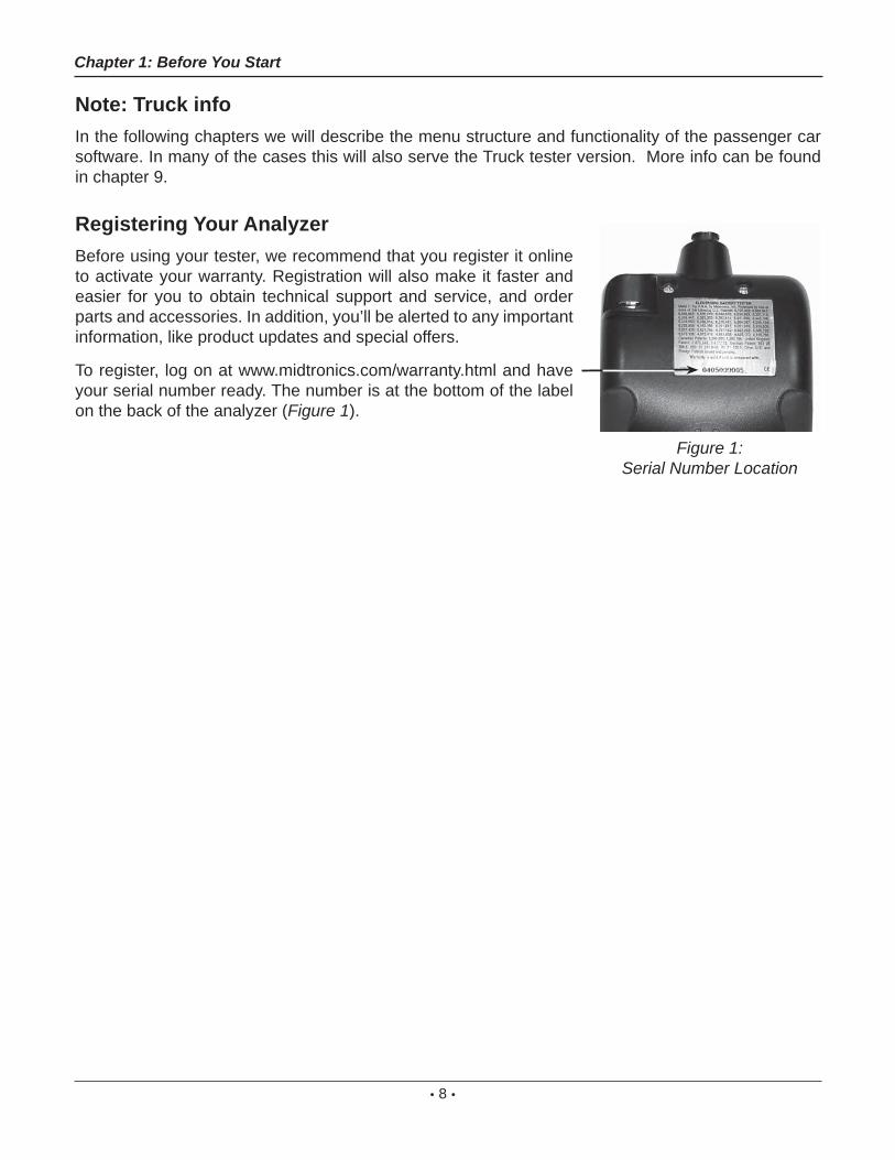
To register, log on at www.midtronics.com/warranty.html and have your serial number ready. The number is at the bottom of the label on the back of the analyzer (Figure 1).
Figure 1: Serial Number Location
Chapter 1: Before You Start

• 9 •
Chapter 2: Description
Chapter 2: Description
Test Leads, Connectors, and Data Ports For the cable test leads, there are two connectors on the top of the tester (Figure 3).
• For the battery test cable, there is a 6-pin connector with a locking ring.
6-pinconnector
IR datatransmitter
IR temperature sensor DB-9
connector for future
expandability
Accessories port
SD card slotfor future upgrades
There are two IR data ports on the top of the Tester (Figure 3).
• An IR data transmitter, which transmits test results to the optional IR printer.
• An IR temperature measurement sensor.
The tester also has a DB-9 connector for future expandability and an SD card slot for future soft-ware upgrades or data logging. (Figure 4).
Figure 3: Top of EXP Figure 4: Bottom of EXP

• 10 •
T h e I n t e r n a l B a t t e r i e sStatus Indicator, which ap-pears in the screen’s top left corner, lets you know the status and charge level of the analyzer’s 6 1.5 V batteries. The X shown in the fi gure shows that the tester is powered by the battery you’re testing to conserve the internal batteries.
Press the two Soft Keys linked to the bottom of the screen to perform the functions displayed above them. The functions change depending on the menu or test process. So it may be helpful to think of the words appearing above them as part of the keys. Some of the more common soft-key functions are SELECT, BACK, and END.
When you connect the tester to a battery it functions as a voltmeter. The voltage read-ing appears above the left soft key until you move to other menus or functions.
In some cases, you can use the Alphanumeric Keypad to enter numerical test parameters instead of scrolling to them with the ARROW keys.
You’ll also use the Alphanu-meric Keys to create and edit customer coupons. The keypad includes characters for punctua-tion. To add a space, press the RIGHT and LEFT ARROW keys simultaneously.
The Selection Area below the Title Bar contains items you se-lect or into which you enter infor-mation. The area also displays instructions and warnings.
The Directional Arrows on the display show you which Arrow Keys to press to move to other
icons or screens. The Up and Down Directional Arrows, for example, let you know to press the
UP and DOWN ARROW keys to display the screens that are above and below the current screen.
The Left and Right Directional Arrows let you know to use the LEFT or RIGHT ARROW keys to highlight an icon for selection.
Another navigational aid is the Scroll Bar along the right side of the screen. The position of its scroll box tells you which menu screen you’re viewing.
The Title Bar shows you the name of the current menu, test tool, utility, or function.
Press the POWER button to turn the Tester on and off. The Tes-ter also turns on automatically when you connect its test leads to a battery.
Whichever way you turn on the Tester, it always highlights the icon and setting you last used for your convenience.
Top or only screen
Middlescreen
Last screen
Scroll Bar
ScrollBox
Chapter 2: Description
Display and KeypadThe keypad and display work together to help you quickly fi nd and use the right tools at the right time. The display also keeps you on track with on-screen navigation aids, directions and messages. Figure 6 shows how the elements on the screen relate to the keypad.
Figure 6: Main Menu and Keypad

• 11 •
Data Entry MethodsTo perform a particular test or function, the tester will ask for different types of information. This means that the methods you use to enter information will change depending on the type of information re-quested. The four types of entry methods are described below.
Typically, the soft key below the right half of the screen confi rms your choice, although the word above it may vary.
Menu iconsA menu icon is a graphical representation of a function you can select, such as the Diode Icon in the DMM Menu. To select an icon, use the LEFT or RIGHT ARROW key to highlight it. To confi rm your selection, press the appropriate soft key.
Option ButtonsSome lists have option buttons before each item. To select an item, use the UP/DOWN ARROW keys to move the dot into the button next to the item you want. You can also use the alphanumeric keypad to enter the number preceding the option button. To confi rm your selection, press the appropriate soft key.
Scrolling ListsScrolling lists contain items that extend above and below the screen or the selection box that contains them. To indicate that there are more items, the symbols appear to the right of the fi rst visible or highlighted item on the list.
To select from this type of list, use the UP/DOWN ARROW keys to scroll to the item, or use the keypad to enter your choice, and press the appropriate soft key.
Alphanumeric EntrySome selections require you to use the alphanumeric keypad. These “user-defi ned” selections have a cursor to the right of the last character.
Use the UP/DOWN ARROW keys to highlight a line for editing. Display the character, symbol, or number you want by rapidly pressing its key as many times as needed. If you pause, the cursor moves to the right. To backspace, press the LEFT ARROW key. Use the RIGHT ARROW key to add a space. Use the UP/DOWN ARROW keys to highlight a line for editing. When fi nished, press the appropriate soft key to save your settings.
Chapter 2: Description

• 12 •
Menu MapsThis section will help you get to your destination while letting you know what test leads you may need when you arrive. The test leads are represented by symbols for their connectors.
Main MenuThe Main Menu is the starting point for all tools and utilities, which are depicted as icons. Some icons lead directly to the function they represent, while others are menu icons that lead to two or more functions. Menu icons are marked here with an asterisk (*) and are mapped on the following pages.
MAIN MENU (Screen 1)
MAIN MENU (Screen 2)
Tests a battery using the battery information you select in a series of screens.
Includes a test counter, data transfer utility, the EXP software version and serial number.
Enables you to view your stored test results and print them to an optional IR printer.
Nine utilities, many of which customize your user interface.
**
*
(voltmeter reading) an icon
(voltmeter reading) an icon
Chapter 2: Description
Quality Control Mode for testing Stock batteries or compound batteries.

• 13 •
An optional IR software and hardware package enables you to transfer test data to a PC.
Info MenuThe Info Menu has three utilities to help you manage your test data, and track the usage and history of your tester.
Displays the total Battery and System Tests per-formed since the tester was fi rst used.
Displays the software version, total tests from fi rst use, and the serial number.
REPORTS
to Main Menu an icon
Chapter 2: Description
Displays the last Battery and System Test results. Sends the results to an optional IR printer.
REPORTS
to Main Menu an icon
Print/View MenuThe tester stores the last test results in its memory until you perform another test. To review or print results before you retest, select a test type in the Print/View Menu.
Displays the last QC Test result. Sends the result to an optional IR printer.
• 14 •
SETUP (Screen 1)
SETUP (Screen 2)
SETUP (Screen 3)
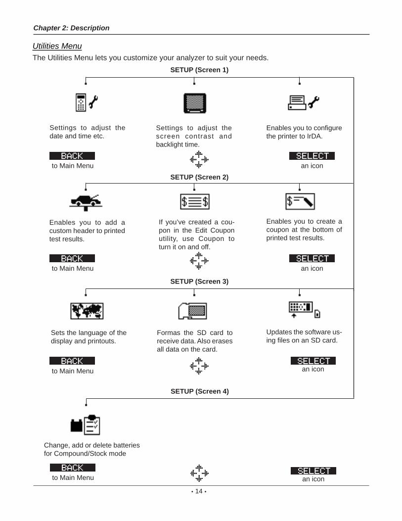
Settings to adjust the date and time etc.
Enables you to add a custom header to printed test results.
Settings to adjust the screen contrast and backlight time.
If you’ve created a cou-pon in the Edit Coupon utility, use Coupon to turn it on and off.
Enables you to create a coupon at the bottom of printed test results.
Sets the language of the display and printouts.
an icon
Utilities MenuThe Utilities Menu lets you customize your analyzer to suit your needs.
to Main Menu an icon
to Main Menu an icon
to Main Menu
Formas the SD card to receive data. Also erases all data on the card.
Updates the software us-ing fi les on an SD card.
Chapter 2: Description
Enables you to confi gure the printer to IrDA.
SETUP (Screen 4)
Change, add or delete batteries for Compound/Stock mode
an iconto Main Menu

• 15 •
Chapter 3: Test Preparation
Inspecting the BatteryBefore starting the test visually inspect the battery for:
• Cracked, buckled, or leaking case. If you see any of these defects, replace the battery.
• Corroded, loose, or damaged cables and connections. Repair or replace them as needed.
• Corrosion on the battery terminals, and dirt or acid on the case top. Clean the case and terminals using a wire brush and a mixture of water and baking soda.
• Low electrolyte level. If the electrolyte level is too low, add distilled water to fill up to 1/2 above the top of the plates and fully charge the battery. Do not overfill.
• Corroded or loose battery tray and hold-down fixture. Tighten or replace as needed.
Testing Out-of-VehicleThe preferred battery test location is in the vehicle. However, if you plan to test out of the vehicle:
• Always disconnect the negative cable from the battery first and reconnect it last.
• Always use a carry tool or strap to lift and transport the battery.
Testing In-VehicleThe preferred test position is at the battery posts. If you must test at a remote-post location, it should have both a positive and negative post.
At the start of the test, make sure all vehicle accessory loads are off, the key is not in the ignition, and the doors are closed.
Connecting the Battery Test CableCAUTION: Do not connect the tester to a voltage source greater than 30 Vdc.
Connect the battery test cable to the tester by fi rst aligning the cable connector’s 6 pins with the holes on top of the tester. Firmly insert the connector and tighten the locking ring.
Connect the clamps to the battery: the red clamp to the positive (+) terminal and the black clamp to the negative (–) terminal.
Chapter 3: Test Preparation

• 16 •
If you connect the clamps in the wrong polarity (positive to negative or negative to positive), the tester displays CLAMPS REVERSED! Reconnect the clamps correctly.
To make sure both sides of the clamps are gripping the terminals, rock the each clamp back and forth. A poor connection will prevent testing, and the tester will display the message CHECK CONNECTION. If the message reappears after you have correctly reconnected the clamps, clean the terminals and reconnect.
The message WIGGLE CLAMPS can indicate that there is no good connection between the clamps and the battery posts. This could be because of corrosion on the posts. Wiggle the clamps and retest.
If there is a problem with the cable resistance the same message can appear. Contact Midtronics for further action.
Note: When the battery voltage is below 0.5 Volt the message CHECK CONNECTION can appear. Fully charge the battery and retest.
Setting User PreferencesBefore starting your test you may want to customize the use of your analyzer by setting preferences in the Utility Menu. The menu has settings for the display’s date and time, the contrast and backlight time, a utility to customize printouts for the optional IR printer, among others.
To conserve the analyzer’s internal batteries, the tester will turn off after 30 seconds of inactivity.
Chapter 3: Test Preparation

• 17 •
Chapter 4: Battery Test
The tester will guide you through the steps of selecting your battery test parameters and interpreting the results. Before you start the test, review the instructions in Chapter 3: Test Preparation.
1. Select the battery LOCATION.1 OUT OF VEHICLE2 IN VEHICLEPress the NEXT soft key to continue. The BACK soft key returns you to the Main Menu at the start of the test and to the previous screen as you progress.
2. Select the Ah value
Read the value from the battery and confi rm with ENTER. Press the UP/DOWN ARROW or enter the value with the keypad.
3. Select the BATTERY TYPE.1 REGULAR2 VRLA
3 SPIRAL4 GEL
Press the NEXT soft key to continue.
4. Select the BATTERY STANDARD1 CCA2 JIS
3 DIN4 SAE
5 IEC 6 EN Press the NEXT soft key to continue.
Chapter 4: Battery Test
• 18 •
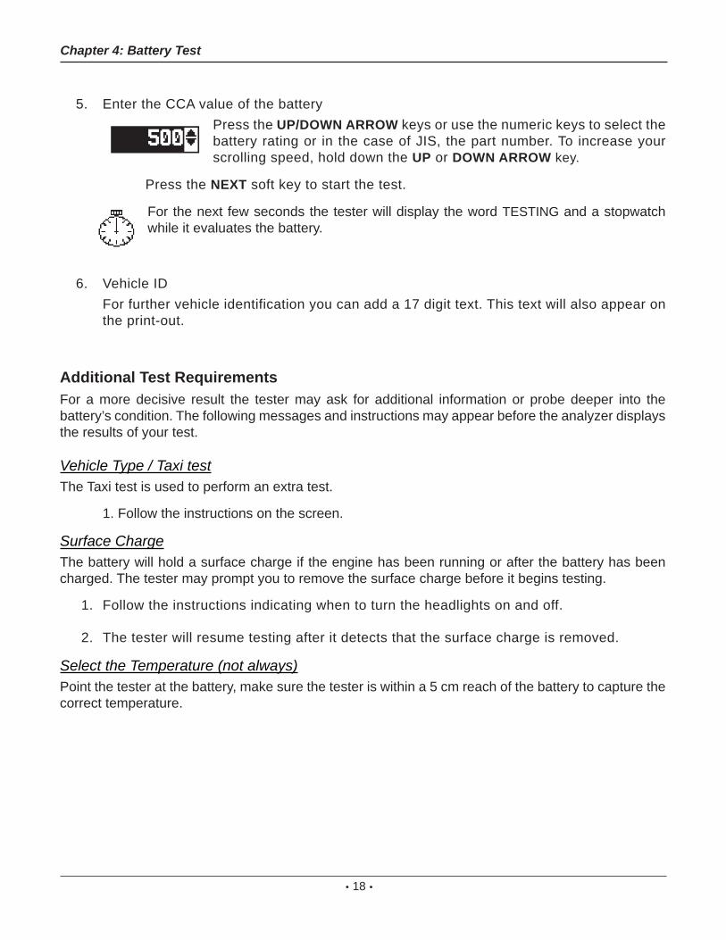
5. Enter the CCA value of the battery Press the UP/DOWN ARROW keys or use the numeric keys to select the
battery rating or in the case of JIS, the part number. To increase your scrolling speed, hold down the UP or DOWN ARROW key.
Press the NEXT soft key to start the test.
For the next few seconds the tester will display the word TESTING and a stopwatch while it evaluates the battery.
6. Vehicle ID For further vehicle identification you can add a 17 digit text. This text will also appear on
the print-out.
Additional Test RequirementsFor a more decisive result the tester may ask for additional information or probe deeper into the battery’s condition. The following messages and instructions may appear before the analyzer displays the results of your test.
Vehicle Type / Taxi testThe Taxi test is used to perform an extra test.
1. Follow the instructions on the screen.
Surface ChargeThe battery will hold a surface charge if the engine has been running or after the battery has been charged. The tester may prompt you to remove the surface charge before it begins testing.
1. Follow the instructions indicating when to turn the headlights on and off.
2. The tester will resume testing after it detects that the surface charge is removed.
Select the Temperature (not always)Point the tester at the battery, make sure the tester is within a 5 cm reach of the battery to capture the correct temperature.
Chapter 4: Battery Test

• 19 •
Before / After ChargeIn some cases the tester may ask you wheather the battery was charged prior to the test. When the vehicle has been driven just prior to the test answer the question with BEFORE CHARGE. Press NEXT to continue.
Deep Scan TestIn some cases the tester may need to further analyze the battery to determine whether the battery should be replaced or it has a signifi cant chance to be recovered. It will then conduct a Deep Scan Test of the battery for a few seconds.
TESTINGDEEP SCAN TECHNOLOGY
PLEASE WAIT . . . . . . . . . .
After the Deep Scan Test the tester will display the results.
The next section describes the battery test decisions and suggests actions to take.
Chapter 4: Battery Test
• 20 •
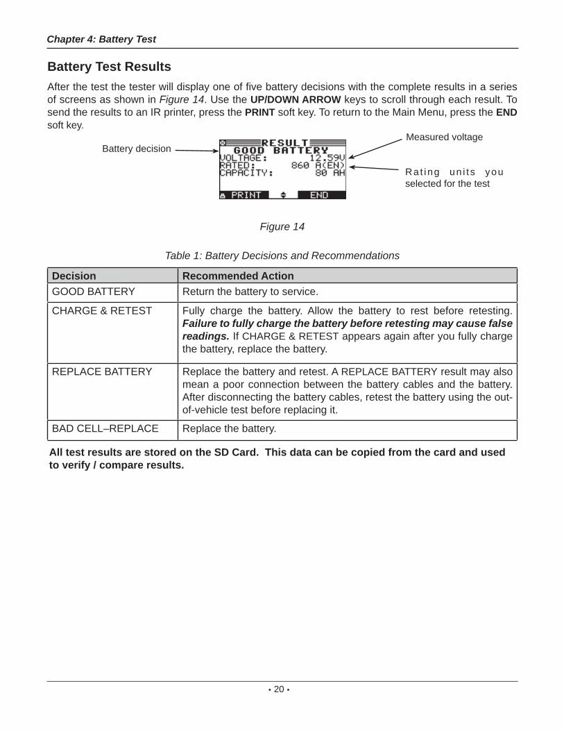
Battery Test ResultsAfter the test the tester will display one of fi ve battery decisions with the complete results in a series of screens as shown in Figure 14. Use the UP/DOWN ARROW keys to scroll through each result. To send the results to an IR printer, press the PRINT soft key. To return to the Main Menu, press the END soft key.
Figure 14
Table 1: Battery Decisions and Recommendations
Decision Recommended ActionGOOD BATTERY Return the battery to service.
CHARGE & RETEST Fully charge the battery. Allow the battery to rest before retesting. Failure to fully charge the battery before retesting may cause false readings. If CHARGE & RETEST appears again after you fully charge the battery, replace the battery.
REPLACE BATTERY Replace the battery and retest. A REPLACE BATTERY result may also mean a poor connection between the battery cables and the battery. After disconnecting the battery cables, retest the battery using the out-of-vehicle test before replacing it.
BAD CELL–REPLACE Replace the battery.
Chapter 4: Battery Test
Battery decisionMeasured voltage
Rat ing un i t s you selected for the test
All test results are stored on the SD Card. This data can be copied from the card and used to verify / compare results.

• 21 •
Chapter 5: QC Test
The tester has the ability to test multiple batteries one after the other without having to input the battery rating / settings.
There are two types of QC tests: the STOCK CONTROL or the COMPOUND TEST. (New vehicles)
STOCK CONTROL is meant for batteries standing in a warehouse or on a pallet where as COMPOUND TESTING is done when the battery is mounted in the (new) vehicle.
1. Select the QC MODE.2. 1 STOCK CONTROL
2 COMPOUND TESTOn the following page you can see the amount of previously performed tests (x of 100). Pressing the left and right arrow keys simultaneously will erase all the tests.Press the NEXT soft key to continue.
3. Select the type of battery selection. When you select the MANUAL ENTRY you will be asked to enter all relevant battery data. When you select PRE SELECTION you can select from a number of batteries that are already in the tester. In the UTILITY menu you can add or delete batteries.
4. 1 MANUAL ENTRY2 PRE SELECTION
Press the NEXT soft key to continue. The MANUAL ENTRY is analogue to the battery test as described in chapter 4.
5. Select the minimum voltage
With new batteries you can look at the open circuit voltage to determine the state of charge. The minimum voltage can be set according to your own quality standard.
6. Select the temperature. Point the tester at the battery under test and store the temperature. Print-out When you print the screen information you will have less information then when you
print from the PRINT/VIEW menu.
Chapter 5: QC Test

• 22 •
Chapter 6: Utilities
The Utility Menu allows you to easily set up your analyzer:
Confi g TesterTIME : AM/PMMODE : 9:07 PMDATE : MMM/DD/YYYFORMAT : 6/17/1/29/2009TEMP. UNITS CWRITE FAIL ASK
Time
1. Use the LEFT/RIGHT ARROWS to highlight the hour, minutes. To rapidly scroll, hold down an ARROW key.
9 : 19 PM
2. Press the SAVE soft key to save your setting or BACK to return to the ADJUST screen.
Mode
Use the LEFT/RIGHT ARROWS to select the option of your choice. You can select the 24-hour or AM/PM mode.
Date
Use the arrow keys to select the desired value.
Format
Use the UP/DOWN ARROWS or press the corresponding numerical key to move the dot to the option button of your choice or enter its number. M/DD/YYY (month/day/year) or DD/MM/YYY (day/month/year) is available.
Temp. Units
The TEMP. UNITS utility enables you to set the units of measure to either Celsius or Fahrenheit.
Chapter 6: Utilities
• 23 •
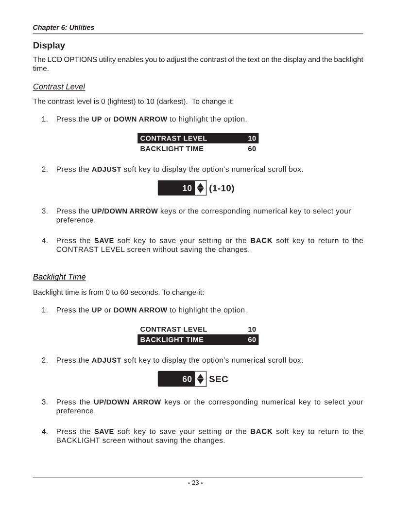
DisplayThe LCD OPTIONS utility enables you to adjust the contrast of the text on the display and the backlight time.
Contrast Level
The contrast level is 0 (lightest) to 10 (darkest). To change it:
1. Press the UP or DOWN ARROW to highlight the option.
CONTRAST LEVEL 10BACKLIGHT TIME 60
2. Press the ADJUST soft key to display the option’s numerical scroll box.
10 (1-10)
3. Press the UP/DOWN ARROW keys or the corresponding numerical key to select your preference.
4. Press the SAVE soft key to save your setting or the BACK soft key to return to the CONTRAST LEVEL screen without saving the changes.
Backlight Time
Backlight time is from 0 to 60 seconds. To change it:
1. Press the UP or DOWN ARROW to highlight the option.
CONTRAST LEVEL 10BACKLIGHT TIME 60
2. Press the ADJUST soft key to display the option’s numerical scroll box.
60 SEC
3. Press the UP/DOWN ARROW keys or the corresponding numerical key to select your preference.
4. Press the SAVE soft key to save your setting or the BACK soft key to return to the BACKLIGHT screen without saving the changes.
Chapter 6: Utilities

• 24 •
Confi g printerUse this option to confi gure your printer. It’s easy to switch your IrDA printer in to the correct protocol.
ShopThe SHOP INFO utility enables you to create a header for your printed test results showing your business location information. Its two information screens contain eight lines of text with up to 16 characters on each line.
Screen 1
1–YOUR SHOP NAME —2–1000 ANY STREET3–YOUR TOWN, STATE4–YOUR POSTAL CODE
5–YOUR COUNTRY —6–YOUR PHONE NUMBER7–WWW.WEBSITE.COM8–YOUR SHOP ID NUMBER
To create or overwrite a header:
1. Press the UP or DOWN ARROW to highlight the line you want to change. The cursor will be blinking to the right of the last character in the line.
2. To move the cursor backward to erase a character, press the LEFT ARROW key; to move the cursor forward, press the RIGHT ARROW key.
3. Insert a character by pressing the key associated with the character as many times as needed.
4. Pess the SAVE soft key to save your setting or the BACK soft key to return to the SHOP INFO screen without saving the changes.
Chapter 6: Utilities

• 25 •
CouponThe COUPON SELECT utility enables and disables the printing of the custom coupon you’ve created in the EDIT COUPON utility.
1. Use the UP/DOWN ARROWS or press the corresponding numerical key to move the dot to the option button of your choice.
1 NO USER COUPON PRINTED2 USER COUPON
2. Press the SAVE soft key to save your setting or the BACK soft key to return to the COUPON SELECT screen without saving the changes.
Edit CouponThe EDIT COUPON utility enables you to create a promotional coupon for your customers that prints at the bottom of every test result. Its two information screens contain eight lines of text with up to 16 characters each.
The editing process is the same as when you create a header for your test results printouts. See the SHOP utility for more information.
LanguageThe LANGUAGE utility enables you to select a language for the display and printouts. To set your preference:
1. Use the UP/DOWN ARROWS or press the corresponding numerical key to move the dot to the option button of your choice. There is a selection of 24 languages.
2. Press the SAVE soft key to save your setting.
Format DiskSelect this utility to format an SD card to receive data or erase all data on the card. The Tester will warn you before formatting the disk and ask you if you want to continue.
UpdateAs software updates become available you’ll be able to use this utility to update the Tester software using fi les on an SD card.
Chapter 6: Utilities

• 26 •
Battery Menu (only for the Quality Control Test)Use this option to ADD BATTERY, DELETE BATTERY, IMPORT LIST or EXPORT LIST.
1 BATTERY LIST2 IMPORT LIST3 EXPORT LIST
When you use the IMPORT or EXPORT function you can use the SD card to store the data.
Chapter 6: Utilities
• 27 •
Chapter 7: Info Menu
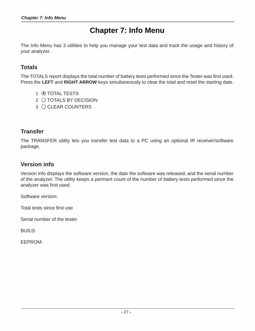
The Info Menu has 3 utilities to help you manage your test data and track the usage and history of your analyzer.
TotalsThe TOTALS report displays the total number of battery tests performed since the Tester was fi rst used. Press the LEFT and RIGHT ARROW keys simultaneously to clear the total and reset the starting date.
1 TOTAL TESTS2 TOTALS BY DECISION3 CLEAR COUNTERS
TransferThe TRANSFER utility lets you transfer test data to a PC using an optional IR receiver/software package.
Version infoVersion info displays the software version, the date the software was released, and the serial number of the analyzer. The utility keeps a permant count of the number of battery tests performed since the analyzer was fi rst used.
Software version:
Total tests since fi rst use
Serial number of the tester
BUILD:
EEPROM:
Chapter 7: Info Menu
• 28 •
Chapter 8: Print/View
The Print/View Menu enables you to view and print the results of the Battery Tests before you perform another test and overwrite the results in memory.
View TestVIEW TEST gives you the option of viewing and printing the results of the Battery and System Tests. To print the results, align the analyzer’s IR transmitter with the printer’s receiver, and select the PRINT soft key. To return to the Main Menu, press the END key.
View QC TestVIEW QC TEST gives you the option of viewing and printing all results of the Quality Control Test. To print the results, align the analyzer’s IR transmitter with the printer’s receiver, and select the PRINT soft key. To return to the Main Menu, press the END key.
Chapter 8: Print/View

• 29 •
Chapter 9: Truck info
IWith update software it is possible to turn the Passenger car software into a combined Passenger car / Truck version. You can contact Midtronics for further information.
Specifi cs for the Truck version:
This software is capable of testing batteries > 115Ah. At the same time it’s possible to test the 2 batteries in the 24V system one after the other.
Battery test
In our case the batteries >115Ah are always of the fl ooded type and therefore you will not be asked to enter the battery technology.
When testing in vehicle you will get the question if you are testing a single battery or the complete set of two. When you test two batteries it’s only necessary to enter the parameters once. After testing the fi rst battery you will be asked to connect to the second battery. All the previous data is stored and at the end compaired as a total set.
Balance test
In the balance test both batteries are tested and compaired to each other. When you select the GENERATE PAIR option it’s always important to test the fi rst battery as GOOD BATTERY. The tester will indicate what to do further.
Chapter 9: Truck info
• 30 •
Chapter 10: Troubleshooting
If you have problems with the display or the Midtronics printer, try these troubleshooting suggestions:
The Display Does Not Turn On• Check the connection to the vehicle battery.
• Press the POWER button.
• The vehicle’s battery may be too low to power the analyzer (below 1 volt). Fully charge the battery and retest.
• If troubleshooting does not solve the problem, contact Midtronics. For more info see page 33
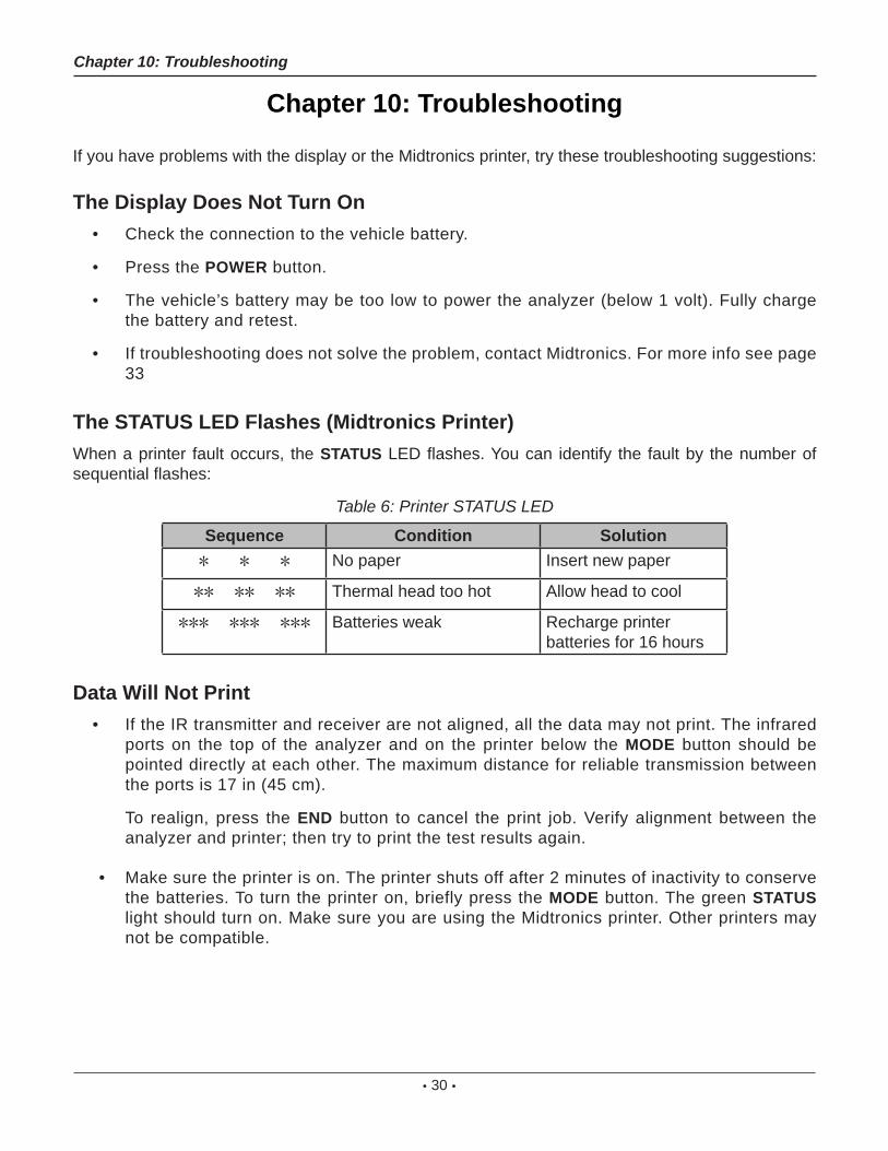
The STATUS LED Flashes (Midtronics Printer)When a printer fault occurs, the STATUS LED fl ashes. You can identify the fault by the number of sequential fl ashes:
Table 6: Printer STATUS LED
Sequence Condition Solution* * * No paper Insert new paper
** ** ** Thermal head too hot Allow head to cool
*** *** *** Batteries weak Recharge printer batteries for 16 hours
Data Will Not Print• If the IR transmitter and receiver are not aligned, all the data may not print. The infrared
ports on the top of the analyzer and on the printer below the MODE button should be pointed directly at each other. The maximum distance for reliable transmission between the ports is 17 in (45 cm).
To realign, press the END button to cancel the print job. Verify alignment between the analyzer and printer; then try to print the test results again.
• Make sure the printer is on. The printer shuts off after 2 minutes of inactivity to conserve the batteries. To turn the printer on, briefly press the MODE button. The green STATUS light should turn on. Make sure you are using the Midtronics printer. Other printers may not be compatible.
Chapter 10: Troubleshooting

• 31 •
• Direct sunlight interferes with infrared data transmission and receiving. If the printer is not receiving data, remove the printer and EXP from direct sunlight. If the printed charac-ters are not clear or are partially missing, recharge the battery and reprint.
Chapter 10: Troubleshooting

• 32 •
Chapter 11: Tester Internal Batteries
The Tester uses 6 AA, 1.5-volt batteries (alkaline recommended) to allow testing of batteries down to 1 volt and supply power while the menu is active. The analyzer can test batteries down to 5.5 volts when the internal batteries are not functioning.
Battery Power IndicatorThe square in the upper left corner of the display indicates the charge level of the battery pack. The square is black when the battery pack is fully charged. It gradually changes to white as the charge level declines. The Tester will display a warning message when the batteries need replacing.
Full Powered by test battery
Decreasing Low
Figure 7: Power Level Indicator for AA Batteries
Replacing the Tester Batteries1. Turn the Tester face down.
2. Remove the screw.
3. Press gently on the ridges above the arrow on the battery compartment cover.
4. Slide the cover in the direction of the arrow and remove the cover.
5. Remove the discharged batteries.
6. Insert new batteries as shown in Figure 22. Make sure the positive and negative terminals are positioned correctly.
7. Insert the door’s tabs into the slots on the analyzer and slide the door closed, making sure the latch locks.
Figure 22: Battery Replacement
Latch Press here Slide in this direction
Chapter 11: EXP Internal Batteries
PATENTSThe inTELLECT™ EXP Expandable Electrical Diagnostic Platform is made in the U.S.A. by Midtronics, Inc. and is protected by one or more of the following U.S. Patents: 4,816,768; 4,825,170; 4,881,038; 4,912,416; 5,572,136; 5,585,728; 5,592,093; 5,757,192; 5,821,756; 5,831,435; 5,914,605; 6,051,976; 6,091,245; 6,163,156; 6,249,124; 6,304,087; 6,310,481; 6,316,914; 6,323,650; 6,351,102; 6,359,441; 6,363,303; 6,392,414; 6,441,585; 6,445,158; 6,456,045; 6,469,511; 6,534,993; 6,544,078; 6,556,019; 6,566,883; 6,586,941; 6,707,303. Canadian Patents: 1,295,680; 1,280,164. United Kingdom Patent: 0,672,248; 0,417,173. German Patent: 693 25 388.6; 689 23 281.0-08; 93 21 638.6. And other U.S. and Foreign patents issued and pending. This product may utilize technology exclusively licensed to Midtronics, Inc. by Johnson Controls, Inc. and/or Motorola, Inc.
LIMITED WARRANTYThis analyzer is warranted to be free of defects in materials and workmanship for a period of two years from date of purchase. Midtronics will, at our option, repair or replace the unit with a remanufactured unit. This limited warranty applies only to the analyzer, and does not cover any other equipment, static damage, water damage, overvoltage damage, dropping the unit, or damage resulting from extraneous causes including owner misuse. Midtronics is not liable for any incidental or consequential damages for breach of this warranty. The warranty is void if owner attempts to disassemble the unit or to modify the cable assembly.
Patents, Limited Warranty, Service
167-000115A-GB 4/09 ©Midtronics, Inc.


