116
INSTRUCTION MANUAL FOR TIME OVERCURRENT RELAY WITH VOLTAGE RESTRAINT BE1-51/27R Publication: 9137200999 Revision: D 07/10

INSTRUCTION MANUAL FOR
TIME OVERCURRENT RELAY WITH VOLTAGE RESTRAINT
BE1-51/27R
Publication: 9137200999 Revision: D 07/10


9137200999 Rev D BE1-51/27R Introduction i
INTRODUCTION This instruction manual provides information about the operation and installation of the BE1-51/27R Time Overcurrent Relay with Voltage Restraint. To accomplish this, the following information is provided:
General Information and Specifications
Controls and Indicators
Functional Description
Installation
Tests and Adjustments
WARNING!
To avoid personal injury or equipment damage, only qualified personnel should perform the procedures in this manual.
NOTE
Be sure that the BE1-51/27R is hard-wired to earth ground with no smaller than 12 AWG copper wire attached to the ground terminal on the rear of the unit case. When the BE1-51/27R is configured in a system with other devices, it is recommended to use a separate lead to the ground bus from each unit.

ii BE1-51/27R Introduction 9137200999 Rev D
First Printing: September 1993
Printed in USA
Copyright © 1993-2010 Basler Electric, Highland Illinois 62249 USA
All Rights Reserved
July 2010
It is not the intention of this manual to cover all details and variations in equipment, nor does this manual provide data for every possible contingency regarding installation or operation. The availability and design of all features and options are subject to modification without notice. Should further information be required, contact Basler Electric.
BASLER ELECTRIC ROUTE 143, BOX 269
HIGHLAND IL 62249 USA http://www.basler.com, [email protected]
PHONE +1 618.654.2341 FAX +1 618.654.2351
CONFIDENTIAL INFORMATION
of Basler Electric, Highland Illinois, USA. It is loaned for confidential use, subject to return on request, and with the mutual understanding that it will not be used in any manner detrimental to the interest of Basler Electric.
9137200999 Rev D BE1-51/27R Introduction iii
REVISION HISTORY The following information provides a historical summary of the changes made to the BE1-51/27R instruction manual (9137200999). Revisions are listed in reverse chronological order.
Manual Revision and Date Change
D, 07/10 Replaced cover drawing and Figure 2-1. (New front panel switches and graphics.)
C, 08/07 Moved content of Section 6, Maintenance to Section 4. Move Time Curve Graphs from Section 1 to Appendix A. Updated front panel illustrations to show laser graphics. Added manual part number and revision to all footers. Updated manual to current style used. Updated power supply burden data in Section 1. Updated Target Indicator description in Section 3.
B, 05/05 Added new information on wide range power supplies. Added new information on case covers. Changed Specifications, Accuracy, Page 1-10 and Isolation, Page 1-
11. Corrected Figure 1-51 and Table 2-4. Deleted Figures 4-8 and 4-9, and references to the Service Manual
(obsolete) in the Introduction and Section 6.
A, 09/03 Enhanced the description of the B and C curves in Section 1. Changes Specifications: Time Overcurrent Pickup Accuracy; Time
Overcurrent Dropout Ratio, and Isolation. Added formula for pickup current and Chart 1-1, Instantaneous
Response Time. Corrected Table 1-3, Figure 1-49, and Tables 2-2 and 2-4. Corrected Figures 5-1 through 5-6 and Test Procedures to reflect
changes in the Specifications. Added Section 7, Changes.
—, 09/93 Initial release

iv BE1-51/27R Introduction 9137200999 Rev D
This page intentionally left blank.

9137200999 Rev D BE1-51/27R Introduction v
CONTENTS
SECTION 1 • GENERAL INFORMATION ................................................................................................ 1-1
SECTION 2 • CONTROLS AND INDICATORS ........................................................................................ 2-1
SECTION 3 • FUNCTIONAL DESCRIPTION ........................................................................................... 3-1
SECTION 4 • INSTALLATION .................................................................................................................. 4-1
SECTION 5 • TESTS AND ADJUSTMENTS ............................................................................................ 5-1
APPENDIX A • TIME OVERCURRENT CHARACTERISTIC CURVES ................................................... A-1

vi BE1-51/27R Introduction 9137200999 Rev D
This page intentionally left blank.
9137200999 Rev D BE1-51/27R General Information i
SECTION 1 ● GENERAL INFORMATION
TABLE OF CONTENTS SECTION 1 ● GENERAL INFORMATION ................................................................................................ 1-1
DESCRIPTION....................................................................................................................................... 1-1 APPLICATION ....................................................................................................................................... 1-1
Backup Protection .............................................................................................................................. 1-1 Residually Connected ........................................................................................................................ 1-1 Operating Characteristics at Reduced Voltages ................................................................................ 1-2
STANDARD FEATURES ....................................................................................................................... 1-3 Time Overcurrent Functions ............................................................................................................... 1-3 Non-Integrating Timing ....................................................................................................................... 1-4 Integrating Timing ............................................................................................................................... 1-5 Built-In Test ........................................................................................................................................ 1-5
OPTIONS ............................................................................................................................................... 1-5 Timing ................................................................................................................................................. 1-5 Sensing Input Type ............................................................................................................................ 1-5 Sensing Input Range .......................................................................................................................... 1-5 Power Supply ..................................................................................................................................... 1-5 Targets ............................................................................................................................................... 1-6 Outputs ............................................................................................................................................... 1-6 Instantaneous Outputs ....................................................................................................................... 1-6 Packaging ........................................................................................................................................... 1-6
MODEL AND STYLE NUMBER DESCRIPTION ................................................................................... 1-6 SPECIFICATIONS ................................................................................................................................. 1-7
Voltage Sensing Inputs ...................................................................................................................... 1-8 Sensing Input Burden ......................................................................................................................... 1-8 Sensing Input Rating .......................................................................................................................... 1-8 Time Overcurrent Pickup Selection Range ........................................................................................ 1-8 Time Overcurrent Pickup Accuracy .................................................................................................... 1-8 Time Overcurrent Dropout Ratio ........................................................................................................ 1-8 Instantaneous Overcurrent Pickup Range ......................................................................................... 1-8 Instantaneous Overcurrent Measuring Accuracy ............................................................................... 1-8 Instantaneous Overcurrent Dropout Ratio ......................................................................................... 1-8 Instantaneous Response .................................................................................................................... 1-8 Time Delay Accuracy ......................................................................................................................... 1-9 Output Circuits .................................................................................................................................... 1-9 Target Indicators ................................................................................................................................ 1-9 Power Supply ..................................................................................................................................... 1-9 Radio Frequency Interference (RFI) ................................................................................................ 1-10 Isolation ............................................................................................................................................ 1-10 Surge Withstand Capability .............................................................................................................. 1-10 UL Recognized ................................................................................................................................. 1-10 GOST-R ............................................................................................................................................ 1-10 Operating Temperature .................................................................................................................... 1-10 Storage Temperature ....................................................................................................................... 1-10 Shock ................................................................................................................................................ 1-10 Vibration ........................................................................................................................................... 1-10 Weight .............................................................................................................................................. 1-10 Case Size ......................................................................................................................................... 1-10
Figures Figure 1-1. Style Number Identification Chart ........................................................................................... 1-7Figure 1-2. Typical Instantaneous Response Time ................................................................................... 1-9

ii BE1-51/27R General Information 9137200999 Rev D
Tables Table 1-1. Timing, Characteristic Curve B4, with BE1-51/27R at 100% and 50% Voltages ..................... 1-2Table 1-2. Timing, Curve B4, BE1-51/27R at 25% Voltage (00 to 10 Time Dial Settings) ....................... 1-2Table 1-3. Timing, Curve B4, BE1-51/27R at 25% Voltage (20 to 99 Time Dial Settings) ....................... 1-3Table 1-4. Power Supply Specifications .................................................................................................... 1-9

9137200999 Rev D BE1-51/27R General Information 1-1
SECTION 1 ● GENERAL INFORMATION DESCRIPTION BE1-51/27R Time Overcurrent Relays are microprocessor-based devices that provide voltage restraint of the phase time overcurrent function. With voltage restraint, the current pickup decreases proportionately with decreasing voltage over the rated voltage range. Instantaneous overcurrent element(s) and the neutral time overcurrent element, when supplied, operate independently of the voltage restraint function. Each relay is available with one, three, or four time overcurrent elements.
APPLICATION Voltage restraint provides an added means of discriminating between load and fault conditions. This allows the time overcurrent pickup to be set below the maximum load (or swing) current. This feature permits the relay to provide dual protection on a generator. For example, either backing up the differential protection for generator faults and/or backing up other relays external to the generator zone. As a back-up function, it must be set with a relatively long delay. Prior to relay time-out, the synchronous impedance of the generator may be limiting fault current to a level comparable to rated. If the regulator is not in service to boost excitation, the steady-state fault current, even for a fault on the machine terminals, will usually be less than rated. The relay pickup must be below generator rated current to insure dependable operation.
Backup Protection
This relay is useful for generator time overcurrent back-up protection for other relaying external to the system. It also provides primary (first line) phase fault protection for small generators not equipped with differential protection.
Phase overcurrent units should be supplied on all three phases. Either three single-phase relays or one three-phase relay when the objective is to protect for phase-phase faults on the other side of a delta-wye power transformer. Currents at the relay for a three-phase fault are in the proportions of 2:1:1 in the three phases, so only one phase sees the higher current level. For this application, each phase time-overcurrent element should be restrained by the phase-to-ground voltage on its phase, rather than by the phase-phase voltage.
Following fault inception, current varies continuously as the field current decays. In addition, for other than a bolted fault on the terminals of a generator, the voltage will not be zero and will vary with time as the fault current decays. If the restraint voltage is between 25 and 100 percent, the time overcurrent element pickup will also vary with the time because of the changing voltage. Because the pickup varies with time, the multiples of pickup, and therefore the timing, will also change. These factors must be considered when coordinating with external protective devices. Section 4 of this manual provides additional coordination information in the paragraphs on setting the relay.
Instantaneous overcurrent elements would not ordinarily be used for a generator back-up function. They would not have acceptable operation for faults external to the generator zone.
Because the phase time-overcurrent pickup will be less than the maximum non-fault current, the relay can misoperate if the voltage signal is interrupted (e.g., a blown voltage transformer fuse). Where two sources of signal voltage are available, the BE1-60 Voltage Balance relay can prevent such a misoperation. This relay compares the output of two signal sources to detect an anomaly in one of these sources and block the operation of those devices connected to that signal source.
Residually Connected
A neutral (ground) overcurrent element can be applied and connected residually to a set of three current transformers on solidly grounded applications or on impedance grounded systems that provide ground fault current approximating rated current level. The neutral element can also be connected to a 10/1 ampere, zero-sequence window current transformer to provide protection on systems producing a minimum of about 20 amperes primary current. Still another alternative would be connecting this device to a current transformer in the neutral of a generator.

1-2 BE1-51/27R General Information 9137200999 Rev D
Operating Characteristics at Reduced Voltages
BE1-51/27R relays adjust the operating parameters based on system voltage. The sensitivity of the relay is increased as the system voltage drops. This provides a means of discriminating between load and fault conditions.
A decrease of the sensed voltage to a point between 100 percent and 25 percent of nominal results in a proportional decrease in the time overcurrent pickup point. Thus, at 50 percent nominal voltage, the time overcurrent relay will pickup at 50 percent of the setting (TAP + Calibration). At voltages above 100 percent nominal, the pickup will be the same as the setting. At voltages below 25 percent of nominal, the pickup will be 25 percent of the setting. Note that the BE1-51/27R is designed to trip at currents less than the setting if the voltage is depressed.
The timing characteristics of the BE1-51/27R continue to operate on multiples of pickup basis. Pickup refers not to the setting, but to the operating point as adjusted for voltage. Thus, with a setting of 5.0 amperes, and system voltage of 50 percent, a current of 5.0 amperes represents 2 times pickup. For a given fault current magnitude, the relay will trip faster at reduced voltage, because the multiples of pickup increases.
Table 1-1 shows the timing characteristics at normal and reduced voltages. The curve is B4 and the time dial is five. The pickup is five amperes. Tables 1-2 and 1-3 show the timing characteristics for multiples of setting as it relates to multiples of pickup with the BE1-51/27R at 25 percent voltage.
Table 1-1. Timing, Characteristic Curve B4, with BE1-51/27R at 100% and 50% Voltages
Fault Current
System Voltage
Effective Pickup
Multiples of Pickup
Approximate Trip Time
4.25 A 100% 5.0 A <1.0 No Trip
4.25 A 50% 2.5 A 1.7 1.499 s
4.25 A 0% 1.25 A 3.4 0.507 s
7.50 A 100% 5.0 A 1.5 1.873 s
7.50 A 50% 2.5 A 3.0 0.772 s
7.50 A 0% 1.25 A 6.0 0.474 s
15.00 A 100% 5.0 A 3.0 0.772 s
15.00 A 50% 2.5 A 6.0 0.474 s
15.00 A 0% 1.25 A 12.0 0.355 s
Table 1-2. Timing, Curve B4, BE1-51/27R at 25% Voltage (00 to 10 Time Dial Settings)
Multiple of Setting
Multiple of Pickup
Time Dial Setting (Seconds)
00 01 02 03 05 07 10
0.38 1.50 0.604 0.856 1.111 1.370 1.873 2.384 3.142
0.43 1.70 0.480 0.688 0.899 1.104 1.499 1.930 2.504
0.50 2.00 0.382 0.539 0.705 0.866 1.194 1.517 1.994
0.55 2.20 0.344 0.484 0.633 0.775 1.063 1.349 1.780
0.63 2.50 0.300 0.419 0.548 0.663 0.918 1.168 1.542
0.68 2.70 0.278 0.387 0.508 0.620 0.850 1.073 1.420
0.75 3.00 0.250 0.354 0.461 0.561 0.772 0.977 1.284
0.88 3.50 0.218 0.308 0.403 0.494 0.672 0.855 1.127
1.00 4.00 0.202 0.281 0.360 0.445 0.602 0.772 1.016
1.13 4.50 0.186 0.261 0.334 0.410 0.557 0.709 0.936
1.25 5.00 0.176 0.243 0.308 0.377 0.506 0.649 0.831
1.50 6.00 0.159 0.220 0.285 0.347 0.474 0.599 0.790

9137200999 Rev D BE1-51/27R General Information 1-3
Multiple of Setting
Multiple of Pickup
Time Dial Setting (Seconds)
00 01 02 03 05 07 10
1.75 7.00 0.151 0.204 0.263 0.320 0.435 0.553 0.727
2.00 8.00 0.142 0.191 0.246 0.300 0.412 0.520 0.683
2.25 9.00 0.136 0.185 0.240 0.290 0.939 0.499 0.654
2.50 10.00 0.130 0.180 0.227 0.277 0.372 0.477 0.622
3.00 12.00 0.123 0.170 0.215 0.262 0.355 0.453 0.593
3.50 14.00 0.118 0.163 0.208 0.250 0.341 0.433 0.566
4.00 16.00 0.117 0.159 0.201 0.243 0.329 0.420 0.548
4.50 18.00 0.112 0.153 0.195 0.237 0.322 0.406 0.537
5.00 20.00 0.111 0.154 0.188 0.231 0.316 0.400 0.526
Table 1-3. Timing, Curve B4, BE1-51/27R at 25% Voltage (20 to 99 Time Dial Settings)
Multiple of Setting
Multiple of Pickup
Time Dial Setting (Seconds)
20 30 40 50 60 80 99
0.38 1.50 5.671 8.222 10.788 13.344 15.919 20.918 25.707
0.43 1.70 4.533 6.556 8.527 10.662 12.694 16.698 20.464
0.50 2.00 3.593 5.207 6.808 8.407 9.986 13.164 16.276
0.55 2.20 3.198 4.636 6.041 7.482 8.906 11.694 14.486
0.63 2.50 2.766 4.003 5.218 6.454 7.682 10.146 12.453
0.68 2.70 2.569 3.720 4.848 5.986 7.130 9.381 11.557
0.75 3.00 2.322 3.358 4.372 5.409 6.434 8.489 10.454
0.88 3.50 2.026 2.931 3.829 4.726 5.627 7.406 9.120
1.00 4.00 1.833 2.647 3.450 4.258 5.076 6.688 8.214
1.13 4.50 1.691 2.438 3.188 3.932 4.673 6.166 7.597
1.25 5.00 1.464 2.117 2.749 3.380 4.022 5.303 6.513
1.50 6.00 1.424 2.060 2.688 3.314 3.949 5.200 6.396
1.75 7.00 1.318 1.897 2.479 3.060 3.644 4.802 5.899
2.00 8.00 1.234 1.792 2.329 2.884 3.430 4.518 5.561
2.25 9.00 1.184 1.704 2.229 2.748 3.273 4.298 5.290
2.50 10.00 1.120 1.604 2.093 2.589 3.070 4.053 4.977
3.00 12.00 1.073 1.551 2.018 2.498 2.971 3.917 4.817
3.50 14.00 1.028 1.481 1.928 2.390 2.841 3.741 4.603
4.00 16.00 0.989 1.430 1.866 2.304 2.741 3.610 4.443
4.50 18.00 0.958 1.392 1.818 2.243 2.667 3.514 4.328
5.00 20.00 0.944 1.372 1.786 2.200 2.619 3.454 4.252
STANDARD FEATURES
Time Overcurrent Functions
Time overcurrent elements pick up over a range of 0.1 to 0.8 amperes, 0.3 to 2.4 amperes, 0.5 to 4.0 amperes, 1.5 to 12.0 amperes, 0.1 to 2.4 amperes, or 0.5 to 12.0 amperes and provide an adjustable time delay that is proportional to the overcurrent. Time delay is initiated when the sensed current exceeds the pickup point. When the current drops below the pickup point, the timing circuit is reset immediately. At reset, the output contacts, if operated, are restored to normal.

1-4 BE1-51/27R General Information 9137200999 Rev D
Adjustment of the overcurrent pickup point is provided by controls on the relay front panel. Time delay is a function of the characteristic curve that has been selected. Time delay is settable from 00 to 99 on the TIME DIAL thumbwheel switch located on the front panel. Curve type is selected either as an option or, in some models, is switch selectable.
Sixty-nine characteristic curves and three timing options are available. They are:
Characteristic curves:
• Seven inverse time • Nine I2t • Seven inverse time with extended timing range • Nine I2t with extended timing range • Five British Standard 142 (E curves) • Seven integrating inverse time • Nine integrating I2t • Seven integrating inverse time with extended timing range • Nine integrating I2t with extended timing range
Timing option Z1 (switch selectable - 16 position) B and C curves:
• Seven inverse time • Nine I2t
Timing option Z1 with option 2-D or 2-E (switch selectable - 16 position) B and C curves:
• Seven inverse time with extended timing range • Nine I2t with extended timing range
Timing option Z2 (switch selectable - 16 position) B and E (British Standard 142) curves:
• Seven inverse time • One I2t • Five British Standard (BS) 142 (E curves)
Timing option Z2 with option 2-D or 2-E (switch selectable - 16 position) B and E (BS142) curves:
• Seven inverse time with extended timing range • One I2t with extended timing range • Five British Standard 142 (E curves)
Timing option Z3 (switch selectable - 16 position) integrating B and C curves:
• Seven integrating inverse time • Nine integrating I2t
Timing option Z3 with option 2-D or 2-E (switch selectable - 16 position) integrating extended B and C curves:
• Seven integrating inverse time with extended timing range • Nine integrating I2t with extended timing range
Characteristic curves are shown by the graphs in Appendix A, Time Overcurrent Characteristic Curves. Note that each graph (i.e. function) consists of a set of representative curves. Each curve (as well as any between-curve interpolation) is selectable by the front panel TIME DIAL using a two-digit destination from 00 to 99. Because of space limitations, each graph shows only 14 of the 100 possible selections.
Non-Integrating Timing
Timing options Z1 and Z2 and the characteristic curves available with those options use non-integrating timing. Non-integrating timing is accomplished by timing at a gate that is not solely dependent on the magnitude of the applied multiple of pickup current. The time-out value is calculated based on the type of time curve characteristic selected, time dial setting, and the magnitude of the applied multiple of pickup current. The time-out value is continuously updated during the timing cycle. When pickup is exceeded, a timer is initiated. When the timer elapsed time exceeds the calculated time-out value, a time trip output signal is generated.
This type of non-integrating time delay characteristic exhibits a dynamic characteristic that is immediately responsive to changes of the applied multiple of pickup current.

9137200999 Rev D BE1-51/27R General Information 1-5
Integrating Timing
Timing option Z3 and the characteristic curves available for that option uses integrating timing. Integrating timing is accomplished by summing time increments that are based on the magnitude of the applied multiple of pickup current, the time curve characteristic selected, and the time dial value. These time increments are summed until a predetermined value is exceeded, then a time trip output signal is generated.
This type of integrating time delay characteristic simulates the operating characteristics of an electromechanical overcurrent relay.
Built-In Test
A built-in test (BIT) switch mounted on the Logic Board provides diagnostic troubleshooting and calibration.
OPTIONS
Timing
An extended timing option multiplies by approximately 5.7, the standard time delays. The resulting curves are shown following the standard curves in Appendix A - e.g., Figure A-1 is timing type B1 and Figure A-2 is the timing type B1 with extended timing range.
When timing option Z1, Z2, or Z3 is specified, a printed circuit board mounted selector switch allows a choice of up to sixteen different time overcurrent functions. Timing option Z1 or Z3 may be further specified as standard or extended time, depending upon option 2 selection.
Sensing Input Type
When single-phase, two-phase-and-neutral, three-phase, or three-phase-and-neutral sensing has been specified, the front panel TAP selector and the front panel TAP CAL control set the pickup point for all phases. An independent front panel TAP (NEUTRAL) selector and front panel CAL (NEUTRAL) control set the neutral pickup point. In addition, for three-phase-and-neutral sensing units, one of the seven sensing input range combinations must be specified.
Relay circuits provide a voltage restraint circuit that varies the selected time overcurrent pickup point proportional to the monitored voltage. As the monitored voltage varies between 100 percent and 25 percent of nominal, the pickup point for each phase varies between 100 percent and 25 percent. Nominal voltage is 100 Vac for 50-hertz systems and 120 Vac for 60-hertz systems. Neutral time overcurrent elements are not restrained. Three-phase voltages are measured phase-to-phase for three wire connections and phase-to-neutral for four wire connections.
Sensing Input Range
For three-phase-and-neutral sensing units, input ranges are:
• 0.5 to 4.0 amperes (phase and neutral) • 1.5 to 12 amperes (phase) and 0.5 to 4.0 amperes (neutral) • 0.5 to 4 amperes (phase) and 1.5 to 12 amperes (neutral) • 1.5 to 12 amperes (phase and neutral) • 0.1 to 0.8 amperes (phase and neutral) • 0.3 to 2.4 amperes (phase) and 0.1 to 0.8 amperes (neutral) • 0.3 to 2.4 amperes (phase and neutral)
For all other units, two ranges are available. They are 0.5 to 12 amperes and 0.1 to 2.4 amperes.
Power Supply
Five power supply options are available. They are:
• 24 Vdc • 48 Vdc • 125 Vdc and 100/125 Vac • 48 Vdc or 125 Vdc and 100/125 Vac • 250 Vdc and 240 Vac

1-6 BE1-51/27R General Information 9137200999 Rev D
Targets
Single-phase relays have two function targets that indicate when the time delay or instantaneous element(s) have operated. On multiple phase relays, additional targets indicate which phase or neutral element(s) operated.
Function targets may be specified as either internally operated or current operated by a minimum of 0.2 amperes through the output trip circuit. When current operated, the output circuit must be limited to 30 amperes for 0.2 seconds, 7 amperes for 2 minutes, and 3 amperes continuously.
Outputs
Optional normally opened, normally closed, or SPDT auxiliary output contacts may be selected. Contacts actuate when the output relay is energized. Internally operated front panel mounted targets, and front panel targets operated by the dc current in the output circuit are available for the time overcurrent and instantaneous overcurrent functions. Optional front panel mounted PUSH-TO-ENERGIZE-OUTPUT pushbuttons allow direct actuation of each output relay for external circuit testing.
Instantaneous Outputs
One or two instantaneous overcurrent outputs are optionally available. Each is adjustable up to 40 times the time overcurrent pickup point. When the sensed current exceeds the instantaneous overcurrent pickup point, an output relay is energized. An independent front panel control (INST 1 or INST 2) adjusts the pickup point for each optional output. If more than one phase is applied to the relay, the instantaneous pickup point will be the same for all phases. If neutral current is sensed, a front panel INST 1 (NEUTRAL) provides adjustment of the neutral pickup point. Instantaneous overcurrent elements are not voltage controlled.
Packaging
Each relay is mounted in a drawout cradle and enclosed in a standard utility style case with either semi-flush or projection mounting (depending upon case style selected). An available test plug (Basler Electric part number 10095) allows the relay to be tested in place without disturbing external control circuit wiring.
MODEL AND STYLE NUMBER DESCRIPTION BE1-51/27R Time Overcurrent Relay electrical characteristics and operational features are defined by a combination of letters and numbers that make up its style number. The model number, together with the style number, describes the options included in a specific device, and appears on the front panel, drawout cradle, and inside the case assembly. Upon receipt of a relay, be sure to check the style number against the requisition and the packing list to ensure that they agree.
Style Number Identification Chart (Figure 1-1) illustrates the manner in which the relay style number is determined. For example, if the style number were U3E-Z1P-B1C1F, the device would have the following characteristics:
U - Three-Phase-and-Neutral sensing, 3-phase, 4-wire voltage restraint 3 - Sensing input range of 1.5 to 12.0 amperes for phase and 0.5 to 4.0 amperes for neutral E - Normally open outputs Z1 - Switch selectable time curves P - Operating power derived from 125 Vdc or 120 Vac B - Current operated targets 1 - One instantaneous element C - Push-to-energize outputs 1 - Normally open auxiliary timed output relay F - Semi-flush mounting

9137200999 Rev D BE1-51/27R General Information 1-7
Figure 1-1. Style Number Identification Chart
SPECIFICATIONS BE1-51/27R Time Overcurrent Relays electrical and physical specifications are as follows:

1-8 BE1-51/27R General Information 9137200999 Rev D
Voltage Sensing Inputs
Rated for 160 Vac continuous at 40 to 70 Hz (nominal frequency 50 or 60 Hz) with a maximum burden of 1 VA.
Sensing Input Burden
Less than 0.1 ohms per phase or neutral.
Sensing Input Rating
The maximum continuous rating is 20 A, 1 second current rating is 50X (times) the maximum tap current selected, or 500 A, whichever is less. For ratings other than those specified by the time curves, the rating is calculated as follows:
T
less) is (whichever A 500 or tap x 50 I =
Where: I = Maximum current T = Time that current flows (in seconds)
Time Overcurrent Pickup Selection Range
Continuously adjustable over the current sensing input ranges specified in the Style Chart (Figure 1-1).
Time Overcurrent Pickup Accuracy
±5% of front panel tap selector setting with TAP CAL control fully CW or ±7% of minimum tap, whichever is greater.
Voltages ≥ Nominal
±10% of calculated pickup value or ±7% of the minimum tap, whichever is greater.
Voltages < Nominal
To find the effective multiple of pickup current use the formula:
V
VII M Nt×=
Where: M = Multiple of tap value current I = Applied current level IT = Tap value VN = Nominal voltage V = Applied voltage level
Time Overcurrent Dropout Ratio
Better than 92% of pickup level.
Instantaneous Overcurrent Pickup Range
Continuously adjustable over the range of 1 to 40 times the time overcurrent pickup setting.
Instantaneous Overcurrent Measuring Accuracy
±2% of pickup setting.
Instantaneous Overcurrent Dropout Ratio
Better than 98% of pickup level.
Instantaneous Response
Figure 1-2 shows the typical response for the instantaneous pickup element.

9137200999 Rev D BE1-51/27R General Information 1-9
Figure 1-2. Typical Instantaneous Response Time
Time Delay Accuracy ±5% of the characteristic curve (Figures A-1 through A-69) for any combination of the front panel TIME DIAL setting and the front panel TAP/TAP CAL overcurrent pickup setting. When evaluating time delay accuracy, time overcurrent pickup accuracy also needs to be considered. Repeatability is within ±2% of setting at 25°C.
Output Circuits
120 Vac: Make, break, and carry 7 Aac continuously Resistive Ratings
250 Vdc: Make and carry 30 Adc for 0.2 s, carry 7 Adc continuously, and break 0.3 Adc 500 Vdc: Make and carry 15 Adc for 0.2 s, carry 7 Adc continuously, and break 0.3 Adc
120 Vac, 125 Vdc, 250 Vdc: Break 0.3 A (L/R = 0.04) Inductive Ratings
Target Indicators Function targets may be specified as either internally operated or current operated by a minimum of 0.2 amperes through the output trip circuit. When current operated, the output circuit must be limited to 30 amperes for 0.2 seconds, 7 amperes for 2 minutes, and 3 amperes continuously.
Power Supply Power for the internal circuitry may be derived from a variety of ac or dc external power sources as indicated in Table 1-4.
Table 1-4. Power Supply Specifications
Type Input Voltage
Burden at Nominal Nominal Range
O (mid range) 48 Vdc 24 to 150 Vdc 1.6 W
P (mid range) 125 Vdc 120 Vac
24 to 150 Vdc 90 to 132 Vac
1.9 W 8.9 VA
R (low range) 24 Vdc 12 to 32 Vdc ∗ 1.7 W
S (mid range) 48 Vdc 125 Vdc
24 to 150 Vdc 24 to 150 Vdc
1.6 W 1.9 W
T (high range) 250 Vdc 240 Vac
68 to 280 Vdc 90 to 270 Vac
2.1 W 14.2 VA
∗ Type R power supply may require 14 Vdc to begin operation. Once operating, the voltage may be reduced to 12 Vdc.

1-10 BE1-51/27R General Information 9137200999 Rev D
Radio Frequency Interference (RFI)
Field-tested using a five-watt, hand-held transceiver operating at random frequencies centered around 144 MHz and 440 MHz, with the antenna located six inches from the relay in both horizontal and vertical planes.
Isolation
In accordance with IEC 255-5 and ANSI/IEEE C37.90, one-minute dielectric (high potential) tests as follows:
All circuits to ground: 2,828 Vdc Input to output circuits: 2,000 Vac or 2,828 Vdc
Surge Withstand Capability
Qualified to ANSI/IEEE C37.90.1-1989, Standard Surge Withstand Capability (SWC) Tests for Protective Relays and Relay Systems.
UL Recognized
UL recognized per Standard 508, UL File No. E97033. Note: Output contacts are not UL recognized for voltages greater than 250 volts and input power supply voltages greater than 150 volts.
GOST-R
Gost-R certified per the relevant standards of Gosstandart of Russia.
Operating Temperature
The operating temperature range is from −40°C (−40°F) to +70°C (+158°F).
Storage Temperature
The storage temperature range is from −65°C (−85°F) to +100°C (+212°F).
Shock
In standard tests, the relay has withstood 15 g in each of three mutually perpendicular planes without structural damage or degradation of performance.
Vibration
In standard tests, the relay has withstood 2 g in each of three mutually perpendicular planes, swept over the range of 10 to 500 Hz for six sweeps, 15 minutes each sweep without structural damage or degradation of performance.
Weight Single-Phase: 13.0 lbs. (5.90 kg) Two-Phase and Neutral: 14.0 lbs. (6.35 kg) Three-Phase: 14.0 lbs. (6.35 kg) Three-Phase and Neutral: 14.4 lbs. (6.53 kg)
Case Size
S1 (Refer to Section 4 for case dimensions.)

9137200999 Rev D BE1-51/27R Controls and Indicators i
SECTION 2 ● CONTROLS AND INDICATORS
TABLE OF CONTENTS SECTION 2 ● CONTROLS AND INDICATORS ....................................................................................... 2-1
INTRODUCTION.................................................................................................................................... 2-1
Figures Figure 2-1. Location of Controls and Indicators ........................................................................................ 2-1
Tables Table 2-1. Controls and Indicators ............................................................................................................ 2-2Table 2-2. Sensing Input Ranges .............................................................................................................. 2-3Table 2-3. Target Installation Configurations ............................................................................................ 2-4

ii BE1-51/27R Controls and Indicators 9137200999 Rev D
This page intentionally left blank.

9137200999 Rev D BE1-51/27R Controls and Indicators 2-1
SECTION 2 ● CONTROLS AND INDICATORS INTRODUCTION BE1-51/27R controls and indicators are located on the front panel and right-side interior. The controls and indicators are shown in Figure 2-1 and described in Table 2-1. Your relay may not have all of the controls and indicators shown and described here.
Figure 2-1. Location of Controls and Indicators

2-2 BE1-51/27R Controls and Indicators 9137200999 Rev D
Table 2-1. Controls and Indicators
A Phase Tap Calibration Control. This single-turn potentiometer adjusts the phase overcurrent pickup threshold between the selected phase tap setting and the next lower tap setting.
B Phase Tap Selector. Selects the phase overcurrent pickup point in conjunction with the front panel Phase Tap Calibration Control (locator A).
C Phase Instantaneous 1 Control. This four-turn potentiometer adjusts the phase instantaneous 1 element trip setting over the range of 1 to 40 times the selected Phase Tap Selector (locator B) setting value. Your relay may be equipped with a Phase Instantaneous 2 Control which provides similar adjustment of the phase instantaneous 2 element trip setting.
D Phase Time Dial Selector. These two knobs set the time delay between sensing of a phase overcurrent condition and closing of the output contacts. See Appendix A for curve selection information.
E Target Indicators. LED indicators latch on when the corresponding output relay is energized by an overcurrent condition. Target indicators are reset by the Target Reset Switch (locator H).
F Push-to-Energize Output Pushbuttons. These recessed pushbuttons are depressed to energize the external trip circuits for testing purposes. A thin, non-conducting rod should be used to depress the buttons. Do not use a screwdriver.
G Tap Selector Table. This front-panel reference lists the high and low setting limits for a particular tap selection.
H Target Reset Switch. Operating this switch resets all active targets (locator E).
I Power Indicator. This LED indicator lights when control power is applied and the relay power supply is functioning.
J Timing Indicators. A Timing LED lights when the corresponding overcurrent pickup point is reached and exceeded.
K Neutral Time Dial Selector. These two knobs set the time delay between sensing of a neutral overcurrent condition and closing of the output contacts. See Appendix A for curve selection information.
L Neutral Tap Calibration Control. This single-turn potentiometer adjusts the phase overcurrent pickup threshold between the selected neutral tap setting and the next lower tap setting.
M Neutral Tap Selector. Selects the neutral overcurrent pickup point in conjunction with the front panel Neutral Tap Calibration Control (locator L).
N Neutral Instantaneous 1 Control. This four-turn potentiometer adjusts the neutral instantaneous 1 element trip setting over the range of 1 to 40 times the selected Neutral Tap Selector (locator M) setting value.
The time overcurrent characteristic curve selector (not shown) is located on the right-side interior. This circuit board mounted switch selects the characteristic curve to be used.
The normal/test slide switch (not shown) is located on the right-side interior. This switch is only used for factory testing and must be in the normal position (towards rear of relay) for proper operation.
The tap range plate (not shown) indicates the terminal connections (high or low) used to select the current sensing input range. The sensing input ranges are listed in Table 2-2.

9137200999 Rev D BE1-51/27R Controls and Indicators 2-3
Table 2-2. Sensing Input Ranges
TAP Range
Plate or Pickup
TAP Selector Current Sensing Terminals
A B C D E F G H I J ØA ØB ØC N
Sensing Input Range 1, Single-Phase ∗
HIGH 2.25 3.00 4.50 5.25 6.75 7.50 9.00 9.75 11.25 12.00 8,7 — — —
LOW 0.75 1.00 1.50 1.75 2.25 2.50 3.00 3.25 3.75 4.00 9,7 — — —
Sensing Input Range 1, Three-Phase ∗
HIGH 2.25 3.00 4.50 5.25 6.75 7.50 9.00 9.75 11.25 12.00 8,7 14,15 17,18 —
LOW 0.75 1.00 1.50 1.75 2.25 2.50 3.00 3.25 3.75 4.00 9,7 13,15 16,18 —
Sensing Input Range 1, Two-Phase-and-Neutral ∗
HIGH 2.25 3.00 4.50 5.25 6.75 7.50 9.00 9.75 11.25 12.00 8,7 — 14,15 17,18
LOW 0.75 1.00 1.50 1.75 2.25 2.50 3.00 3.25 3.75 4.00 9,7 — 13,15 16,18
Sensing Input Range 2, Three-Phase-and-Neutral
Phase or Neutral 0.75 1.00 1.50 1.75 2.25 2.50 3.00 3.25 3.75 4.00 8,9 13,14 15,16 17,18
Sensing Input Range 3, Three-Phase-and-Neutral
Phase 2.25 3.00 4.50 5.25 6.75 7.50 9.00 9.75 11.25 12.00 8,9 13,14 15,16 —
Neutral 0.75 1.00 1.50 1.75 2.25 2.50 3.00 3.25 3.75 4.00 — — — 17,18
Sensing Input Range 4, Three-Phase-and-Neutral
Phase 0.75 1.00 1.50 1.75 2.25 2.50 3.00 3.25 3.75 4.00 8,9 13,14 15,16 —
Neutral 2.25 3.00 4.50 5.25 6.75 7.50 9.00 9.75 11.25 12.00 — — — 17,18
Sensing Input Range 5, Three-Phase-and-Neutral
Phase or Neutral 2.25 3.00 4.50 5.25 6.75 7.50 9.00 9.75 11.25 12.00 8,9 13,14 15,16 17,18
Sensing Input Range 6, Three-Phase-and-Neutral
Phase or Neutral 0.15 0.20 0.30 0.35 0.45 0.50 0.60 0.65 0.75 0.80 8,9 13,14 15,16 17,18
Sensing Input Range 7, Three-Phase-and-Neutral
Phase 0.45 0.60 0.90 1.05 1.35 1.50 1.80 1.95 2.25 2.40 8,9 13,14 15,16 —
Neutral 0.15 0.20 0.30 0.35 0.45 0.50 0.60 0.65 0.75 0.80 — — — 17,18
Sensing Input Range 8, Three-Phase-and-Neutral
Phase or Neutral 0.45 0.60 0.90 1.05 1.35 1.50 1.80 1.95 2.25 2.40 8,9 13,14 15,16 17,18
Sensing Input Range 9 (All Other Sensing Types) ∗
HIGH 0.45 0.60 0.90 1.05 1.35 1.50 1.80 1.95 2.25 2.40 Same as Range 1
LOW 0.15 0.20 0.30 0.35 0.45 0.50 0.60 0.65 0.75 0.80 Same as Range 1
∗ For relays with sensing input ranges 1 or 9, connect the system wiring to the current sensing terminals for the desired range (HIGH or LOW).

2-4 BE1-51/27R Controls and Indicators 9137200999 Rev D
Refer to Table 2-3 for target installation configurations.
Table 2-3. Target Installation Configurations
Sensing Input Type
Number of Instantaneous Elements Targets Installed (Types A and B)
None One Two Element Function
A B C N TIME INST 1 INST 2
M, N
X X
X X X
X X X X
R, S X X X X
X X X X X X
U, W X X X X X
X X X X X X X
B, C X X X X X X
X X X X X X
E, F X X X X X X X
X X X X X X X
Y, Z X X X X X
X X X X X X

9137200999 Rev D BE1-51/27R Functional Description i
SECTION 3 ● FUNCTIONAL DESCRIPTION
TABLE OF CONTENTS SECTION 3 ● FUNCTIONAL DESCRIPTION ........................................................................................... 3-1
GENERAL .............................................................................................................................................. 3-1 BLOCK DIAGRAM ANALYSIS .............................................................................................................. 3-1
Power Supply ..................................................................................................................................... 3-2 Current Sensing ................................................................................................................................. 3-2 Tap Select and Tap Cal ...................................................................................................................... 3-2 Voltage Sensing ................................................................................................................................. 3-2 Multiplexor .......................................................................................................................................... 3-2 Analog-To-Digital Converter and Level Detector ............................................................................... 3-2 Time Trip Comparator and Scaler ...................................................................................................... 3-2 Voltage Restraint ................................................................................................................................ 3-2 Microprocessor (Not Shown) .............................................................................................................. 3-3 Instantaneous Overcurrent (Options 1-1 and 1-2) ............................................................................. 3-3 Timed and Instantaneous Outputs ..................................................................................................... 3-3 Auxiliary Outputs ................................................................................................................................ 3-3 Push-to-Energize Pushbuttons........................................................................................................... 3-3 Power Supply Status Output (Option 3-6) .......................................................................................... 3-4 Target Indicators ................................................................................................................................ 3-4
Figures Figure 3-1. Functional Block Diagram ....................................................................................................... 3-1

ii BE1-51/27R Functional Description 9137200999 Rev D
This page intentionally left blank.

9137200999 Rev D BE1-51/27R Functional Description 3-1
SECTION 3 ● FUNCTIONAL DESCRIPTION GENERAL BE1-51/27R Time Overcurrent Relays are microprocessor-based devices that provide voltage restraint of the phase time overcurrent functions.
BLOCK DIAGRAM ANALYSIS The following block diagram analysis is referenced to Figure 3-1. A microprocessor (not illustrated in Figure 3-1) processes signals, performs logic functions, and all of the time overcurrent computations.
Figure 3-1. Functional Block Diagram

3-2 BE1-51/27R Functional Description 9137200999 Rev D
Power Supply
Operating power for the relay circuitry is supplied by a wide range, electrically isolated, low-burden power supply. Power supply operating power is not polarity sensitive. The front panel power LED and power supply status output indicate when the power supply is operating. Power supply specifications are listed in Table 1-4.
Current Sensing
All relay models (except three-phase-and-neutral units) have two sensing ranges for each phase. Each high/low sensing range has its own set of input terminal connections.
• Five ampere CTs have: LOW (0.5 A to 4.0 A) and HIGH (1.5 A to 12.0 A). • One ampere CTs have: LOW (0.1 A to 0.8 A) and HIGH (0.3 A to 2.4 A).
Three-phase-and-neutral sensing units, however, have one of four possible combinations of input sensing ranges with one range for neutral and one range for the phases.
• Five ampere CTs have: 0.5 A to 4.0 A and 1.5 A to 12.0 A. • One ampere CTs have: 0.1 A to 0.8 A and 0.3 A to 2.4 A.
Tap Select and Tap Cal
Front panel TAP selectors and TAP CAL controls are provided for selection and precise adjustment of the phase and neutral (if provided) time overcurrent pickup points. The front panel TAP selectors, ten-position BCD weighted rotary switches, select the desired current sensing pickup point, while the front panel TAP CAL controls provide precise adjustment between the selected setting and the next lower setting.
Voltage Sensing
Input voltage for each phase to be monitored are applied to the voltage sensing circuits. Each voltage sensing circuit consists of an input transformer, rectifier, and filter Analog voltages from the voltage sensing circuits are applied to the multiplexor. Note that neutral is not monitored for voltage.
Multiplexor
The multiplexor sequentially switches a voltage representing each of the sensed input currents to the analog-to-digital converter and level detector.
Analog-To-Digital Converter and Level Detector
When the voltage representing the actual sensed inputs meets or exceeds the selected pickup point, this circuit converts the level to a corresponding binary number and applies it to a time trip comparator and scaler circuit and to a counter for calculation of the required time delay.
Time Trip Comparator and Scaler
This circuit accepts both the binary number representing the detected current level and the desired time delay characteristic selected by the front panel TIME DIAL, then computes the required time delay before the timed output relay will be energized. Time delay characteristics are shown in the curves located in Appendix A. If extended timing range options 2-D or 2-E is present, the time delay characteristic curves are modified so that the time delay is approximately 5.7 times the derived value.
Time delay computations are updated continuously so that changes in the overcurrent condition are monitored and result in a corresponding change in the time delay. A software counter begins counting when the initial binary number is received from the analog-to-digital converter and level detector. The counter measures the elapsed time of the overcurrent condition, and resets if the current decreases below the pickup point. This continuously increasing binary number is then passed to the comparator.
Voltage Restraint
Voltage restraint compares the binary number representing the monitored voltage with the fixed nominal voltage limit (100 Vac for 50-hertz systems and 120 Vac for 60-hertz systems). When the voltage is between 100 percent and 25 percent of the nominal voltage, the circuit automatically lowers the selected time overcurrent pickup point proportionally. Instantaneous overcurrent operation, if present, is not affected. Neutral is not monitored for voltage, nor is the neutral time overcurrent pickup point restrained.

9137200999 Rev D BE1-51/27R Functional Description 3-3
When the voltage is above the 100 percent limit, the pickup point is restrained to 100 percent. When the voltage is below the 25 percent limit, the pickup point remains at the 25 percent point.
For a given level of current above pickup, a lowering of the pickup point, via voltage restraint effectively increases the multiples of current. This shifts the time delay characteristic to the right on the multiples-of-pickup-current axis (characteristic curves) as voltage drops from 100 percent to 25 percent.
To find the effective multiple of pickup current use the formula:
V
VII M Nt×=
Where: M = Multiple of tap value current I = Applied current level IT = Tap value VN = Nominal voltage V = Applied voltage level
Microprocessor (Not Shown)
Some of the circuitry already discussed is part of the microprocessor and no definite lines are drawn to separate the functions. The microprocessor compares the desired time delay (from the time trip comparator and scaler) with the actual elapsed time from the counter. When the elapsed time reaches the intended delay, the timed output relay is energized. During the time delay period, the front panel TIMING indicator (i.e. pickup) associated with the detected phase is illuminated.
If targets are present, the front panel TIME FUNCTION target will be tripped, and the A, B, C, or N ELEMENT target associated with the detected phase will be tripped. See Table 2-3 for the types of targets that are present (depending upon relay configuration).
If option 3 is present, an auxiliary output relay (with N.O., N.C., or SPDT contacts) is also actuated when the timed output relay energizes.
Instantaneous Overcurrent (Options 1-1 and 1-2)
Input current levels applied to the time overcurrent circuitry are also passed to the instantaneous overcurrent circuitry. These levels are compared to the setting of the front panel INST 1 adjust and the front panel INST 1 (NEUTRAL) adjust (if present). If the input current level is above the setting, the output driver energizes the instantaneous 1 output relay. If the instantaneous 2 option is present, the input level is also compared with the setting of the front panel INST 2 adjust to energize the instantaneous 2 output relay. Not that the current level settings for the instantaneous overcurrent element will always be from 1 to 40 times above the front panel TAP and TAP (NEUTRAL) settings of the time overcurrent element.
If target type A or B is present, the front panel INST 1 target and the front panel INST 2 targets are tripped when their respective output relay is energized, along with the front panel A, B, C or N ELEMENT targets (if present) associated with the detected phases. (See Section 2, Controls and Indicators, for the types of targets that can be present depending upon the relay configuration.)
Timed and Instantaneous Outputs
Each output signal (representing either time overcurrent or instantaneous overcurrent) from each monitored phase (or neutral) is applied to the respective output driver. Each output driver supplies operating current to energize the associated output relay. Either normally open (output type E) or normally closed (output type G) contacts may be specified. (The contact configurations of all output relays for a given model will be the same.)
Auxiliary Outputs
In addition to the output relays, an auxiliary relay, having the same or a different contact configuration, may be specified. Both the output and the auxiliary relays will remain energized for the duration of the overcurrent condition.
Push-to-Energize Pushbuttons
If either option 2-C or 2-E is present, each individual output relay can be directly energized for test purposes by the actuation of a front panel PUSH-TO-ENERGIZE OUTPUT pushbutton. The pushbutton is actuated by the insertion of a thin, non-conducting rod through an access hole in the front panel.

3-4 BE1-51/27R Functional Description 9137200999 Rev D
Power Supply Status Output (Option 3-6)
Power supply status output relays have a set of normally closed contacts that are energized open during power-up. If either or both power supply output legs (+12 Vdc or −12 Vdc) fails, the power supply status output relay is de-energized and the output contacts close. Shorting bars across the output contacts are held open by the installed connection plug. When the relay is removed from service by removing the connection plug, the shorting bars are closed.
Target Indicators
Target indicators are optional components selected when a relay is ordered. The electronically latched and reset targets consist of red LED indicators located on the relay front panel. A latched target is reset by operating the target reset switch on the front panel. If relay operating power is lost, any illuminated (latched) targets are extinguished. When relay operating power is restored, the previously latched targets are restored to their latched state.
A relay can be equipped with either internally operated targets or current operated targets.
The relay trip outputs are directly applied to drive the appropriate target indicator. Each indicator is illuminated regardless of the current level in the trip circuit.
Internally Operated Targets
A current operated target is triggered by closure of the corresponding output contact
Current Operated Targets
and
Note that the front panel function targets (TIMED, INST 1, etc.) may be either internally or current operated. Phase and neutral indicators are current operated
the presence of at least 200 milliamperes of current flowing in the trip circuit.
only if the instantaneous options are not included and
if current operated targets are specified.
NOTE
Prior to August 2007, BE1-51/27R target indicators consisted of magnetically latched, disc indicators. These mechanically latched target indicators have been replaced by the electronically latched LED targets in use today.

9137200999 Rev D BE1-51/27R Installation i
SECTION 4 ● INSTALLATION
TABLE OF CONTENTS SECTION 4 ● INSTALLATION .................................................................................................................. 4-1
INSTALLATION...................................................................................................................................... 4-1 RELAY OPERATING GUIDELINES AND PRECAUTIONS .................................................................. 4-1 MOUNTING ............................................................................................................................................ 4-1 CONNECTIONS..................................................................................................................................... 4-7 MAINTENANCE ................................................................................................................................... 4-17 STORAGE ............................................................................................................................................ 4-17 SETTING THE RELAY ........................................................................................................................ 4-17
General ............................................................................................................................................. 4-17 Relay Setting Concepts .................................................................................................................... 4-17 Setting Example ............................................................................................................................... 4-19 Coordination with Feeder 51 Relay for Fault 1 ................................................................................. 4-21 Checking Coordination with Relay 67 for Fault 2 ............................................................................. 4-21 Checking Coordination with Relay 67 for Fault 3 ............................................................................. 4-22 Neutral Element Backup Settings .................................................................................................... 4-23
Figures Figure 4-1. Outline Dimensions, Side View, Semi-Flush Mounted, Double-Ended Case ......................... 4-2Figure 4-2. Outline Dimensions, Side View, Projection Mounted, Double-Ended Case ........................... 4-3Figure 4-3. Outline Dimensions, Front View, Case Cover ......................................................................... 4-4Figure 4-4. Panel Cutting and Drilling Dimensions, Semi-Flush Mounting, Double-Ended Case ............. 4-5Figure 4-5. Panel Drilling Dimensions, Projection Mounting, Double-Ended Case .................................. 4-6Figure 4-6. Typical External Connections, Current Operated Targets, DC Powered ............................... 4-7Figure 4-7. Typical Sensing External Connections, Sensing Input Type M or N ...................................... 4-8Figure 4-8. Typical Sensing External Connections, Sensing Input Type R or S ....................................... 4-8Figure 4-9. Typical Sensing External Connections, Sensing Input Type U or W ...................................... 4-9Figure 4-10. Typical Sensing External Connections, Sensing Input Type B or C ..................................... 4-9Figure 4-11. Typical Sensing External Connections, Sensing Input Type E or F ................................... 4-10Figure 4-12. Typical Sensing External Connections, Sensing Input Type Y or Z ................................... 4-10Figure 4-13. Typical Internal Diagram, Sensing Input Type M or N ........................................................ 4-11Figure 4-14. Typical Internal Diagram, Sensing Input Type Y or Z ......................................................... 4-12Figure 4-15. Typical Internal Diagram, Sensing Input Type B or C ......................................................... 4-13Figure 4-16. Typical Internal Diagram, Sensing Input Type R or S ......................................................... 4-14Figure 4-17. Typical Internal Diagram, Sensing Input Type E or F ......................................................... 4-15Figure 4-18. Typical Internal Diagram, Sensing Input Type U or W ........................................................ 4-16Figure 4-19. Relay Signals and Current Pickup Example for 3-Phase Fault (XE=0.65 X”D) .................... 4-18Figure 4-20. Relay Signals and Current Pickup Example for 3-Phase Fault (XE=2 X”D) ......................... 4-18Figure 4-21. System Example ................................................................................................................. 4-20Figure 4-22. Relay 51/27 Coordination with Relay 67 for Fault 3 Example ............................................ 4-23
Tables Table 4-1. Three-Phase Fault Currents ................................................................................................... 4-20

ii BE1-51/27R Installation 9137200999 Rev D
This page intentionally left blank.

9137200999 Rev D BE1-51/27R Installation 4-1
SECTION 4 ● INSTALLATION INSTALLATION BE1-51/27R relays are shipped in sturdy cartons to prevent damage during transit. Upon receipt of a relay, check the model and style number against the requisition and packing list to see that they agree. Inspect the relay for shipping damage. If there is evidence of damage, file a claim with the carrier, and notify your sales representative or Basler Electric.
If the relay will not be installed immediately, store it in its original shipping carton in a moisture- and dust-free environment. Before placing the relay in service, it is recommended that the test procedures of Section 5, Tests and Adjustments be performed.
RELAY OPERATING GUIDELINES AND PRECAUTIONS Before installing or operating the relay, not the following guidelines and precautions.
• For proper current operated target operation, a minimum current of 200 milliamperes must flow through the output trip circuit.
• If a wiring insulation test is required, remove the connection plugs and withdraw the relay from its case.
MOUNTING Because the relay is of solid-state design, it does not have to be mounted vertically. Any convenient mounting angle may be chosen. Refer to Figures 4-1 through 4-5 for relay outline dimensions and panel drilling diagrams.
CAUTION
When the connection plugs are removed, the relay is disconnected from the operating circuit and will not provide system protection. Always be sure that external operating (monitored) conditions are stable before removing a relay for inspection, test, or service.
NOTE
Be sure that the relay is hard-wired to earth ground with no smaller than 12 AWG copper wire attached to the ground terminal on the rear of the case. When the relay is configured in a system with other devices, it is recommended to use a separate lead to the ground bus from each device.

4-2 BE1-51/27R Installation 9137200999 Rev D
Figure 4-1. Outline Dimensions, Side View, Semi-Flush Mounted, Double-Ended Case
D2853-2206-15-99

9137200999 Rev D BE1-51/27R Installation 4-3
Figure 4-2. Outline Dimensions, Side View, Projection Mounted, Double-Ended Case

4-4 BE1-51/27R Installation 9137200999 Rev D
Figure 4-3. Outline Dimensions, Front View, Case Cover

9137200999 Rev D BE1-51/27R Installation 4-5
Figure 4-4. Panel Cutting and Drilling Dimensions, Semi-Flush Mounting, Double-Ended Case

4-6 BE1-51/27R Installation 9137200999 Rev D
Figure 4-5. Panel Drilling Dimensions, Projection Mounting, Double-Ended Case

9137200999 Rev D BE1-51/27R Installation 4-7
CONNECTIONS Be sure to check the model and style number of a relay before connecting and energizing the relay. Incorrect wiring may result in damage to the relay. Except where noted, connections should be made with wire no smaller than 14 AWG.
Typical external connections are shown in Figures 4-6 through 4-12. Internal connections are shown in Figures 4-13 though 4-18.
To prevent an inductive overload of the relay contacts, it is necessary to break the trip circuit externally through the 52a contacts.
Relay circuitry is connected to the case terminals by removable connection plugs (1 plug for 10-terminal cases and 2 plugs for 20-terminal cases). Removal of the connection plug(s) opens the normally open trip contact circuits and shorts the normally closed trip circuits before opening the power and sensing circuits.
Figure 4-6. Typical External Connections, Current Operated Targets, DC Powered
P0050-03
4-8 BE1-51/27R Installation 9137200999 Rev D
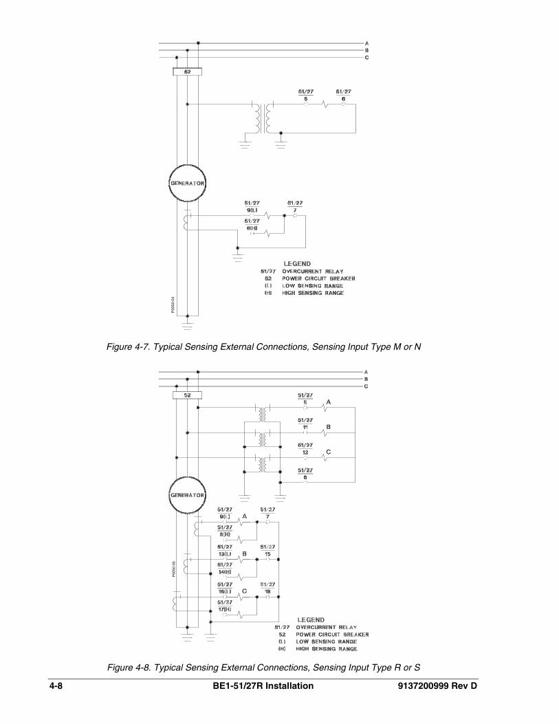
Figure 4-7. Typical Sensing External Connections, Sensing Input Type M or N
Figure 4-8. Typical Sensing External Connections, Sensing Input Type R or S
P00
50-0
4P
0050
-05

9137200999 Rev D BE1-51/27R Installation 4-9
Figure 4-9. Typical Sensing External Connections, Sensing Input Type U or W
Figure 4-10. Typical Sensing External Connections, Sensing Input Type B or C
P00
50-0
6P
0050
-07

4-10 BE1-51/27R Installation 9137200999 Rev D
Figure 4-11. Typical Sensing External Connections, Sensing Input Type E or F
Figure 4-12. Typical Sensing External Connections, Sensing Input Type Y or Z
P00
50-0
8P
0050
-09

9137200999 Rev D BE1-51/27R Installation 4-11
Figure 4-13. Typical Internal Diagram, Sensing Input Type M or N

4-12 BE1-51/27R Installation 9137200999 Rev D
Figure 4-14. Typical Internal Diagram, Sensing Input Type Y or Z

9137200999 Rev D BE1-51/27R Installation 4-13
Figure 4-15. Typical Internal Diagram, Sensing Input Type B or C

4-14 BE1-51/27R Installation 9137200999 Rev D
Figure 4-16. Typical Internal Diagram, Sensing Input Type R or S

9137200999 Rev D BE1-51/27R Installation 4-15
Figure 4-17. Typical Internal Diagram, Sensing Input Type E or F

4-16 BE1-51/27R Installation 9137200999 Rev D
Figure 4-18. Typical Internal Diagram, Sensing Input Type U or W

9137200999 Rev D BE1-51/27R Installation 4-17
MAINTENANCE BE1-51/27R relays require no preventative maintenance other than a periodic operational check. If the relay fails to function properly, contact Technical Sales Support at Basler Electric to coordinate repairs.
STORAGE This device contains long-life aluminum electrolytic capacitors. For devices that are not in service (spares in storage), the life of these capacitors can be maximized by energizing the device for 30 minutes once per year.
SETTING THE RELAY
General
Phase time overcurrent elements (BE1-51/27R relays) can be coordinated with external protection in a conventional manner by assuming that the pickup current is 25 percent of nominal. This is the case when the restraint voltage is 25 percent or less. When the restraint voltage exceeds 25 percent, pickup current exceeds 25 percent of nominal and the relay is slower than if pickup current was fixed at 25 percent. Assuming a fixed 25 percent pickup simplifies calculations and provides an added safety margin because the BE1-51/27R relay is the last step in the coordination for an external fault.
Neutral (ground) time overcurrent and all instantaneous overcurrent functions operate independently of the voltage control circuits. Therefore, these elements (overcurrent functions) can be set in the normal manner. They are set independently of each other except that the instantaneous setting is 1 to 40 times the associated time overcurrent element pickup. The instantaneous element pickup should be set for at least 120 percent of the maximum current that can be seen by the relay for an external fault where operation is not desired.
Neutral time overcurrent pickup must be set above the maximum expected normal unbalance. In addition, for residually connected elements, added relay current can result from dissimilar errors in the three current transformers. These errors are greater for the lower accuracy class current transformers. A neutral element pickup of ten percent of the circuit rating will ordinarily be above non-fault unbalances for a solidly grounded system. Lower settings are appropriate and safe for impedance grounded systems or for ungrounded protected equipment connections.
When choosing the time delay setting in a generator back-up application, for a motor starting application, or during acceleration after a fault is cleared, the limiting condition may be the percentage of generator rating that is motor load and not coordination for an external fault. The percentage of generator rating that is motor load needs to be considered when setting the relay.
A nominal phase time overcurrent pickup (with rated restraint voltage) of 200 percent of generator rating can prevent undesirable tripping during a severe recoverable swing. This pickup is still low enough to provide sufficient sensitivity for faults.
Relay Setting Concepts
Figure 4-19 plots fault current in multiples of generator rating (assuming no voltage regulator boosting) and relay pickup as a percent of nominal. The relay tap must be selected so that pickup in multiples of generator rating is less than the fault current shown in the Figure 4-19 example.
Restraint voltage (V) is proportional to the drop across external reactance (XE), and decays along with the fault current (I) that is developed by the generator. Initial voltage is 40 percent of rated, so the phase time overcurrent pickup is also 40 percent of nominal. At about 0.04 seconds after fault inception, restraint voltage drops below 25 percent and the pickup current flattens to 25 percent. During the shaded portion of the graph, the relay operates slower than it would if the pickup current was constant at 25 percent of nominal. This occurs for a minor interval compared to the total relay operating time, so the increased pickup has a negligible effect on operating time.

4-18 BE1-51/27R Installation 9137200999 Rev D
Figure 4-19. Relay Signals and Current Pickup Example for 3-Phase Fault (XE=0.65 X”D)
Figure 4-20 shows an example similar to Figure 4-19, but the higher external reactance (XE = 2X"D) to the fault develops a higher restraint voltage. In Figure 4-20, the shaded area of the graph where pickup exceeds 25 percent of nominal is much larger than the shaded area in Figure 4-19. (This is the area where the relay operates slower.) If we assume a fixed 25 percent of nominal pickup current, a significant margin in the time coordination with external protection is added, although the log scale tends to exaggerate this effect.
Figure 4-20. Relay Signals and Current Pickup Example for 3-Phase Fault (XE=2 X”D)
9137200999 Rev D BE1-51/27R Installation 4-19
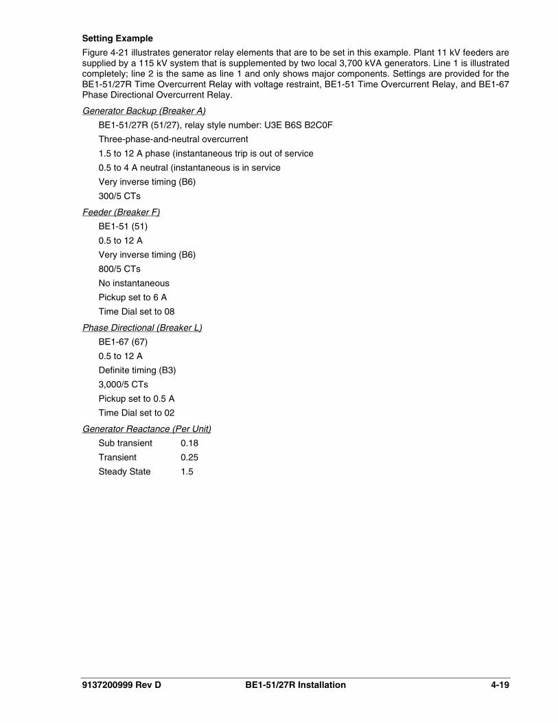
Setting Example
Figure 4-21 illustrates generator relay elements that are to be set in this example. Plant 11 kV feeders are supplied by a 115 kV system that is supplemented by two local 3,700 kVA generators. Line 1 is illustrated completely; line 2 is the same as line 1 and only shows major components. Settings are provided for the BE1-51/27R Time Overcurrent Relay with voltage restraint, BE1-51 Time Overcurrent Relay, and BE1-67 Phase Directional Overcurrent Relay.
BE1-51/27R (51/27), relay style number: U3E B6S B2C0F
Generator Backup (Breaker A)
Three-phase-and-neutral overcurrent
1.5 to 12 A phase (instantaneous trip is out of service
0.5 to 4 A neutral (instantaneous is in service
Very inverse timing (B6)
300/5 CTs
BE1-51 (51)
Feeder (Breaker F)
0.5 to 12 A
Very inverse timing (B6)
800/5 CTs
No instantaneous
Pickup set to 6 A
Time Dial set to 08
BE1-67 (67)
Phase Directional (Breaker L)
0.5 to 12 A
Definite timing (B3)
3,000/5 CTs
Pickup set to 0.5 A
Time Dial set to 02
Sub transient 0.18
Generator Reactance (Per Unit)
Transient 0.25
Steady State 1.5

4-20 BE1-51/27R Installation 9137200999 Rev D
Figure 4-21. System Example
Downstream current in Table 4-1 is the current in the downstream relay with which the BE1-51/27R elements must coordinate. The currents are the changes resulting from the fault assuming a driving point voltage of 11 kV. Actual currents will be the sum of the table values plus the pre-fault load currents. Transient level currents are based on use of the generator transient reactance. Steady-state level currents are based on use of generator steady-state reactance and assuming no generator regulator boost. Note that the table values apply for 3-phase faults. Transient level currents in generators for a phase-to-phase fault will be about equal to the 3-phase current values. Steady-state level currents in the generators will be higher for a phase-to-phase fault.
Table 4-1. Three-Phase Fault Currents
Level Out of Service Fault Loc. Fault Current - A @ 11 kV
Downstream Generator
Transient T2 1 7256 776
Steady State T2 1 5961 129
Transient ― 2 7256 776
Transient T2 2 1552 776
Steady State T2 2 258 129
Transient ― 3 713 713
Steady State ― 3 127 127

9137200999 Rev D BE1-51/27R Installation 4-21
Coordination with Feeder 51 Relay for Fault 1
(1) Multiples of pickup in 51 relay at transient level:
( ) 7.6960
72566800/5
7256==
(2) Relay 51 time at 7.6 multiples (from B6 curves) @ 08 time dial: 0.31 s.
(3) Set 51/27 pickup:
( )( ) Primary A 3401.73 113700 1.75
= ( ) Secondary A 7.5300/5 340
=
(4) Set the 51/27 time to provide 0.3 s coordinating interval:
A776 @ s 0.61 0.3 31.0 =+
(5) 51/27 voltage equals 0, so pickup = 0.25 x 5.7 = 1.4 A (84 A Primary)
(6) 51/27 multiples:
2.9
53001.4
776=
×
(7) 51/27 TIME DIAL (from B6 curve, @ 9.2 multiple and 0.61 s): 23.
(8) Multiples of pickup in 51 relay at steady-state level:
( ) 2.66 800/5
5961=
(9) 51/27 time at 6.2 multiples: 0.36 s.
(10) 51/27 multiples at 129 A:
5.1
53001.4
129=
×
(11) 51/27 time at 1.5 multiples: 9.0 s.
(12) Relay 51/27 coordinates with relay 51 over the full range of fault currents with transformer T2 out of service. With both T1 and T2 in service, relay 51 sees more current and operates faster than the above times. If the fault is not interrupted by the feeder breaker, the generators will be tripped at time falling between 0.61 s and 9.0 s.
Checking Coordination with Relay 67 for Fault 2
(1) 67 multiples at transient level with T2 in service:
( ) 24 3000/5 5.0
7256=
(2) 67 time at 24 multiples (B3 curve, TIME DIAL 02): 0.15 s.
(3) 67 multiples at transient level with T2 out of service:
3300
1552=
(4) 67 time at 3 multiples: 0.23 s.
(5) Note that a failure of the differential protection (87T) for fault 2 with T2 out of service is a double contingency. Coordination of 51/27 relays with 67 relays does occur at the transient level (0.61 vs. 0.35 s). As the current decays, the times converge and cross because the 67 relay pickup is 300 amperes vs. 97 amperes for 51/27 relays (see calculation below for steady-state multiple of 0.86 for the 67 relays). So coordination may not be achieved for this double contingency with the generator

4-22 BE1-51/27R Installation 9137200999 Rev D
regulators out of service. Boosting by the regulators will partially arrest the decay of current. In addition, the decay will be less for a phase-phase fault.
(6) 67 multiples at steady-state level with T2 out:
86.0300258
=
(7) For a failure of Breaker L to open, the 51 relays on transformer T2 will operate as well as the generator relays to clear fault 2. For a failure of the T1 differential relays (87T), the T2 51 relays should coordinate with the 67 relays so T2 and the generators will remain in service.
Checking Coordination with Relay 67 for Fault 3
(1) 67 multiples at transient level with T2 in service:
4.2300713
=
(2) 67 time at 2.4 multiples: 0.26 s.
(3) 51/27 transient level voltage (reactor and transformer T1 drop): 8%.
(4) 51/27 multiples at transient level:
4.797
713=
(5) 51/27 transient level time at 7.4 multiples and TIME DIAL setting of 22: 0.72 s.
(6) 51/27 relays coordinate with 67 relays for a high-side fault at the transient level. However, it appears that the current may drop below the 67 relay pickup (300 amperes) before this relay can operate. Should the 67 relays fail to operate, the 51/27 relays will trip the generators. Figure 4-22 plots these two relay characteristics. If the generator is fully loaded at 194 amperes with a 0.85 PF, the superposition of this current and the fault current at −90° yields a total current of 831 amperes at the transient level and 282 amperes at the steady-state level with no regulator boosting. The relays are selective down to about 350 amperes.
(7) Assuming that the 67 relays will not operate for fault 3, the generators will be unnecessarily tripped if the line relaying fails to operate or if breaker R fails to interrupt the fault. Redundant line relaying will minimize the need for generator tripping. Use of a breaker-failure timer set to about 0.25 seconds would avoid generator tripping for a failure of breaker R to interrupt.

9137200999 Rev D BE1-51/27R Installation 4-23
Figure 4-22. Relay 51/27 Coordination with Relay 67 for Fault 3 Example
Neutral Element Backup Settings
(1) The 51N element has no relays to coordinate with because the generators are ungrounded. An instantaneous element, if used, must be set above the maximum false residual current that can be developed due to dissimilar current transformer saturation during an external three-phase fault. Similarly, the time setting of the time overcurrent element must ride through this transient resulting from current transformer saturation.
(2) Ground current contribution from each transformer is 485 amperes. Normal total current level is:
A9704852 =×
(3) Set the time element for 0.8-ampere pickup.
(4) Set the time element (51N) at 0.2 s for 970 amperes primary (see B3 curve):
DIALTIME 08 and multiples 200.860
970=
×
(5) Set the instantaneous (50N) pickup at 5 amperes:
7.60.85
=
The maximum ground fault current is:
pickupRelay the times 2.3300970
=

4-24 BE1-51/27R Installation 9137200999 Rev D
This page intentionally left blank.

9137200999 Rev D BE1-51/27R Tests and Adjustments i
SECTION 5 ● TESTS AND ADJUSTMENTS
TABLE OF CONTENTS SECTION 5 ● TESTS AND ADJUSTMENTS ........................................................................................... 5-1
GENERAL .............................................................................................................................................. 5-1 REQUIRED TEST EQUIPMENT ........................................................................................................... 5-1 OPERATIONAL TEST ........................................................................................................................... 5-1
Preliminary Instructions ...................................................................................................................... 5-1 Time Overcurrent Pickup Test............................................................................................................ 5-5 Timed Output Test .............................................................................................................................. 5-7 Instantaneous Overcurrent Pickup Test ............................................................................................. 5-8 Voltage Restraint Test ........................................................................................................................ 5-9
ADJUSTMENTS OF CONTROLS FOR RELAY OPERATION ........................................................... 5-10 TAP and TAP (NEUTRAL) Selector Setting ..................................................................................... 5-10 Time Overcurrent Curve Selection (Timing Type Z1, Z2, and Z3 Only) .......................................... 5-11 Time Delay Selection ....................................................................................................................... 5-12 Neutral Time Delay Selection ........................................................................................................... 5-12 INST 1 Control Setting ..................................................................................................................... 5-12 INST 2 Control Setting ..................................................................................................................... 5-13
Figures Figure 5-1. Test Setup for Sensing Input Type M or N (Single-Phase Sensing) ...................................... 5-2Figure 5-2. Test Setup for Sensing Input Type R or S (Three-Phase Sensing) ........................................ 5-3Figure 5-3. Test Setup for Sensing Input Type U or W (Three-Phase with Neutral Sensing) ................... 5-3Figure 5-4. Test Setup for Sensing Input Type B or C (Three-Phase, Delta Configuration) ..................... 5-4Figure 5-5. Test Setup for Sensing Input Type E or F (Three-Phase with Neutral Sensing) .................... 5-4Figure 5-6. Test Setup for Sensing Input Type Y or Z (Two-Phase with Neutral Sensing) ....................... 5-5

ii BE1-51/27R Tests and Adjustments 9137200999 Rev D
This page intentionally left blank.

9137200999 Rev D BE1-51/27R Tests and Adjustments 5-1
SECTION 5 ● TESTS AND ADJUSTMENTS GENERAL Procedures in this section are for use in testing and adjusting a relay for the desired operation in a protective scheme. If a relay fails an operational test, or if an adjustment discloses a faulty relay, refer to Section 4, Installation, Maintenance.
REQUIRED TEST EQUIPMENT Minimum test equipment required for relay testing and adjustment is listed below. Refer to Figures 5-1 through 5-6 for test setups.
• Appropriate ac or dc power source for relay operation. • Appropriate ac source (50 or 60 hertz as appropriate) for voltage and current testing. • Dc external power source for output relay(s) test setup and timer input. • Relay test set capable of delivering 40 amperes. A higher capability is needed for instantaneous
settings above 40 amperes. • Timer. • One shunt resistor for providing minimum target load.
OPERATIONAL TEST
Preliminary Instructions
Perform the following steps before going on to any testing.
Step 1. Connect the relay test setup in accordance with Figures 5-1 through 5-6, depending upon the sensing input type for your relay (see Figure 1-1, Style Number Identification Chart).
(a) Sensing Input Type M or N (Single-Phase Sensing). Figure 5-1 Refer to .
Ensure that timed output terminals 1 and 10 are connected.
(b) Sensing Input Type R or S (Three-Phase Sensing). Figure 5-2 Refer to .
Ensure that timed output terminals 1 and 10 are connected.
(c) Sensing Input Type U or W (Three-Phase with Neutral Sensing). Figure 5-3 Refer to .
Ensure that the timed output terminals 1 and 10 are connected. Also, verify that either A, B, or C current sense terminals are connected initially (N terminals will be connected later in the test).
(d) Sensing Input Type B or C (Three-Phase Sensing). Figure 5-4 Refer to .
Ensure that the timed output terminals 1 and 10 are connected. Also, verify that either A, B, or C current sense terminals are connected initially (N terminals will be connected later
NOTE
For relays having the above sensing, only the front panel LOW range current sense terminal(s) should be connected for a complete check of the relay.
NOTE
For relays having the above sensing, only the from panel LOW range current sense terminal(s) should be connected for a complete check of the relay.
For all three-phase relays, the test signals must connect to both the current and voltage terminals for the same phase.

5-2 BE1-51/27R Tests and Adjustments 9137200999 Rev D
in the test). Ensure that the voltage sense terminals and the current sense terminals are connected to the same phase.
(e) Sensing Input Type E or F (Three-Phase with Neutral Sensing). Figure 5-5 Refer to .
Ensure that the timed output terminals 1 and 10 are connected. Also, verify that either A, B, or C current sense terminals are connected initially (N terminals will be connected later in the test).
(f) Sensing Input Type Y or Z (Two-Phase with Neutral Sensing). Figure 5-6 Refer to .
Ensure that the timed output terminals 1 and 10 are connected. Also, verify that either A, B, or C current sense terminals are connected initially (N terminals will be connected later in the test).
Step 2. Remove the relay front cover.
Step 3. Set the front panel TIME DIAL selector and, if present, the front panel TIME DIAL (NEUTRAL) selector to 99.
Step 4. Adjust the front panel INST 1 and INST 2 controls, if present, fully clockwise (CW).
Step 5. Adjust the front panel TAP CAL control, and if present, the front panel TAP (NEUTRAL) control fully CW.
Step 6. Ensure that the relay front panel TARGETS, if present, are reset.
Step 7. Apply 100% of nominal voltage based on the sensing input type for your relay.
Figure 5-1. Test Setup for Sensing Input Type M or N (Single-Phase Sensing)

9137200999 Rev D BE1-51/27R Tests and Adjustments 5-3
Figure 5-2. Test Setup for Sensing Input Type R or S (Three-Phase Sensing)
Figure 5-3. Test Setup for Sensing Input Type U or W (Three-Phase with Neutral Sensing)

5-4 BE1-51/27R Tests and Adjustments 9137200999 Rev D
Figure 5-4. Test Setup for Sensing Input Type B or C (Three-Phase, Delta Configuration)
Figure 5-5. Test Setup for Sensing Input Type E or F (Three-Phase with Neutral Sensing)

9137200999 Rev D BE1-51/27R Tests and Adjustments 5-5
Figure 5-6. Test Setup for Sensing Input Type Y or Z (Two-Phase with Neutral Sensing)
Time Overcurrent Pickup Test
This test checks the minimum and maximum overcurrent pickup points of the time overcurrent element.
Step 1. Perform the preliminary instructions.
Step 2. Set the front panel TAP selector to A.
Step 3. Adjust the test set, for an overcurrent threshold having one of the following values:
(a) 0.5 for relays with Sensing Input Range 1, 2, or 4.
(b) 1.5 A for relays with Sensing Input Range 3 or 5.
Step 4. Slowly adjust the front panel TAP CAL control CCW until the front panel TIMING indicator illuminates.
RESULT: For the phase minimum overcurrent pickup point of 0.5 A (Step 3a, above) or 1.5 A (Step 3b, above) the front panel TAP CAL control should be near its maximum CCW limit.
Step 5. Adjust the front panel TAP CAL control fully CW to allow measurement of the actual overcurrent pickup point at the A setting of the front panel TAP selector. Note that the front panel TIMING indicator will extinguish. Do not disturb this setting.
Step 6. Slowly increase the current toward the value of the front panel TAP selector A setting until the front panel TIMING indicator illuminates. Do not disturb this setting.
Step 7. Record the current reading and remove input current.
RESULT: The recorded value should be within ±5% of the front panel TAP selector A setting for the phase minimum overcurrent pickup point for the time overcurrent.
Step 8. Set the front panel TAP selector to J.
Step 9. Slowly adjust the test set, increasing the overcurrent threshold toward the value of the front panel TAP selector J setting until the front panel TIMING indicator just illuminates. Do not disturb this setting.
NOTE
During this test, disregard any indication on the test setup timer.

5-6 BE1-51/27R Tests and Adjustments 9137200999 Rev D
Step 10. Record the current reading and remove input current.
RESULT: The recorded value should be within ±5% of the front panel TAP selector J setting for the phase maximum overcurrent pickup point for the time overcurrent element.
Step 11. Perform the following steps as appropriate for the correct sensing input types.
(a) Sensing Input Type M or N (Single-Phase Sensing).
(b)
This concludes the time overcurrent test. Proceed to the timed output test.
Sensing Input Type Y or Z (Two-Phase and Neutral Sensing).Figure 5-6
Remove the power and reconnect the input sensing to the remaining phases as shown in , each time repeating Steps 1 through 10. For neutral testing, continue with Step 12.
(c) Sensing Input Type B, C, R, or S (Three-Phase Sensing).
(d)
Remove the power and reconnect the input sensing to each of the remaining phases as shown in Figures 5-4 and 5-6, each time repeating Steps 1 through 10.
Sensing Input Type E, F, U, or W (Three-Phase with Neutral Sensing).
Step 12. Perform the preliminary instructions.
Remove the power and reconnect the input sensing to each of the remaining phases as shown in Figure 5-3 and 5-5, each time repeating Steps 1 through 10. For neutral testing, continue with Step 12.
For the neutral sensing (terminals 17 and 18), connect the relay as shown in Figures 5-3 and 5-5, then perform the following steps (Steps 13 through 21).
Step 13. Set the front panel TAP (NEUTRAL) selector to A.
Step 14. Adjust the test set for an overcurrent threshold having one of the following values:
(a) 0.5 A for relays with Sensing Input Range 2 or 3.
(b) 1.5 A for relays with Sensing Input Range 4 or 5.
Step 15. Slowly adjust the front panel CAL (NEUTRAL) control CCW until the front panel TIMING indicator illuminates.
RESULT: For the neutral minimum overcurrent pickup point of 0.5 A (Step 16a, above) or 1.5 A (Step 16b, above) the front panel CAL (NEUTRAL) control should be near its maximum CCW limit.
Step 16. Adjust the front panel CAL (NEUTRAL) control fully CW to allow measurement of the actual overcurrent pickup point at the A setting of the front panel TAP (NEUTRAL) selector. Note that the front panel TIMING (NEUTRAL) indicator will extinguish. Do not disturb this setting.
Step 17. Slowly increase the current toward the value of the front panel TAP (NEUTRAL) selector A setting until the front panel TIMING (NEUTRAL) indicator illuminates. Do not disturb this setting.
Step 18. Record the current reading and remove input current.
RESULT: The recorded value should be within ±5% of the front panel TAP (NEUTRAL) selector A setting for the neutral minimum overcurrent pickup point for the time overcurrent.
Step 19. Set the front panel TAP (NEUTRAL) selector to J.
Step 20. Slowly adjust the test set, increasing the overcurrent threshold toward the value of the front panel TAP (NEUTRAL) selector J setting until the front panel TIMING (NEUTRAL) indicator just illuminates. Do not disturb this setting.
Step 21. Record the current reading and remove input current.
RESULT: The recorded value should be within ±5% of the front panel TAP (NEUTRAL) selector J setting for the neutral maximum overcurrent pickup point for the time overcurrent element.
NOTE
Ensure that the voltage sense terminals and current sense terminals are connected to the same phase.

9137200999 Rev D BE1-51/27R Tests and Adjustments 5-7
Timed Output Test
This test checks the accuracy of the time overcurrent characteristic delay.
Step 1. Verify that the preliminary instructions have been performed.
Step 2. (Timing type Z1, Z2, or Z3 only.) Select the desired time current characteristic curve.
Step 3. Set the front panel TAP selector to B.
Step 4. Adjust the front panel TIME DIAL to 20.
Step 5. Adjust the test set for an overcurrent threshold of precisely 5 times the front panel TAP selector B setting.
Step 6. Apply input current to the relay and initiate the test setup timer.
Step 7. Observe that the appropriate front panel TIMING indicator illuminates and when the time delay ends that the timed output relay is energized.
RESULTS: (1) The appropriate front panel TIMING indicator extinguishes.
(2) The test setup timer stops. (Record count for use in Step 9.)
(3) If target type A or B is present:
(a) The front panel FUNCTION-TIME target (if present) trips.
(b) The appropriate front panel ELEMENT target A, B, or C (if present) trips.
Step 8. Remove input current and (if present) reset the relay front panel targets.
Step 9. On the appropriate time overcurrent curve chart (Figures A-1 through A-69), locate the line representing 5 times the tap value (from Step 5) where it intersects the particular curve representing the front panel TIME DIAL setting of 20 (from Step 4). The resulting time delay value in seconds should be within ±5% of the timer reading [from Step 7(2)].
Step 10. Adjust the front panel TIME DIAL to 40, 60, and 99, each time repeating Steps 6 through 9.
NOTE
For relays having three-phase sensing (Sensing Input Type B, C, R, or S) only a single input phase needs to be connected, since this is sufficient for a complete test of the Time Delay. For relays that include neutral sensing (Sensing Input Type E, F, U, N, Y, or Z), this test includes reconnecting the Test Output to the Neutral Sensing terminals for testing the Timed Output during neutral sensing.
NOTE
Due to delays inherent in the test equipment, the time delay for the following test may appear to exceed these limits.
NOTE
For relays having two-phase-and-neutral, three-phase, or three-phase-and-neutral sensing (Sensing Input Types B, C, E, F, R, S, U, W, Y, or Z) it is not necessary to repeat this test for the remaining phases.
For relays having two-phase-and-neutral, or three-phase-and-neutral sensing (Sensing Input Types E, F, U, W, Y, or Z) perform Steps 11 through 20.
For relays having single-phase or three-phase sensing (Sensing Input Types B, C, M, N, R, or S) with instantaneous overcurrent option 1-1 or 1-2, proceed to the instantaneous overcurrent test. All other relays proceed to the voltage restraint test.
5-8 BE1-51/27R Tests and Adjustments 9137200999 Rev D
Step 11. Remove the power and reconnect the test output to the neutral current sensing input of the relay as shown in Figures 5-3 and 5-5 (terminals 17 and 18).
Step 12. Set the front panel TAP (NEUTRAL) selector to B.
Step 13. Rotate the front panel CAL (NEUTRAL) control fully CW.
Step 14. Rotate the front panel TIME DIAL (NEUTRAL) to 20.
Step 15. Ensure that all relay targets have been reset.
Step 16. Adjust the test set for an overcurrent threshold of precisely 5 times the front panel TAP (NEUTRAL) selector B setting as measured by the ammeter.
Step 17. Apply input current to the relay and initiate the test setup timer.
RESULTS: Observe that the appropriate front panel TIMING (NEUTRAL) indicator illuminates.
Step 18. When the time delay ends, the timed output relay is energized.
RESULTS: (1) The front panel TIMING (NEUTRAL) indicator extinguishes.
(2) The test setup timer stops. (Record count for use in Step 20.)
(3) If target Type A or B is present:
(a) Front panel FUNCTION-TIME target (if present) trips.
(b) Appropriate front panel ELEMENT target A, B, or C (if present) trips.
Step 19. Remove input current and (if present) reset the relay front panel targets.
Step 20. On the appropriate time overcurrent curve chart (Figures A-1 through A-69), locate the line representing 5 times the tap value (from Step 5) where it intersects the particular curve representing the front panel TIME DIAL (NEUTRAL) setting of 20 (from Step 14). The resulting time delay value in seconds should be within ±5% of the timer reading [from step 18(2)].
Instantaneous Overcurrent Pickup Test
This test checks the minimum overcurrent pickup points for Instantaneous 1 and (if present) Instantaneous 2 outputs.
Step 1. Perform the preliminary instructions.
Step 2. Reconnect the test setup to the INST 1 output terminals 2 and 10 as shown in Figures 5-1 through 5-6. Note that the timer may be removed from the test setup at this time.
Step 3. Set the TAP selector to A.
Step 4. Turn the front panel INST 1 control fully CCW to establish a pickup point of 1 times the TAP selector A setting.
Step 5. Slowly adjust the test set, increasing the overcurrent threshold toward the value of the front panel TAP selector A setting until the Instantaneous 1 output relay energizes.
NOTE
Due to delays inherent in the test equipment, the time delay may appear to exceed these limits. This concludes the timed output test.
Relays having instantaneous overcurrent option 1-1 or 1-2 only
NOTE
proceed to the Instantaneous Overcurrent Pickup Test.
For relays having three-phase sensing (Sensing Input Types B, C, R, or S), only a single input phase is connected since this is sufficient for a complete test of the instantaneous overcurrent sensing and output.
For relays that include neutral sensing (Sensing Input Types E, F, U, W, Y, or Z), this test includes reconnecting the test output to the neutral sensing terminals for testing the instantaneous 1 output during neutral sensing.

9137200999 Rev D BE1-51/27R Tests and Adjustments 5-9
RESULT: If target Type A or B is present:
(a) The front panel FUNCTION-INST 1 target (if present) will trip.
(b) The appropriate front panel ELEMENT target A, B, or C (if present) will trip.
Step 6. Remove input current. Record the test set current setting.
RESULT: The recorded value should be equal to or less than the front panel TAP selector A setting for the minimum overcurrent pickup point for the instantaneous 1 overcurrent element.
Step 7. Reset the relay front panel targets (if present).
Step 8. Turn the front panel INST 1 control fully CW to establish a pickup point of 40 times the front panel TAP selector A setting.
Step 9. Adjust the test set to approximately 35 times the front panel TAP selector A setting.
Step 10. Slowly adjust the test set further toward an overcurrent threshold of 40 times the front panel TAP selector A setting until the instantaneous 1 output relay energizes. Do not disturb this setting.
RESULT: If target Type A or B is present:
(a) The front panel FUNCTION-INST 1 target (if present) will trip.
(b) The appropriate front panel ELEMENT target A, B, or C (if present) will trip.
Step 11. Record the current reading. Remove input current (the front panel TIMING indicator should extinguish).
RESULT: The recorded value should be greater than 40 times the front panel TAP selector A setting for the maximum overcurrent pickup point for the instantaneous 1 overcurrent element.
Step 12. For the neutral sensing, connect the relay as shown in Figures 5-3 and 5-5, then repeat Steps 2 through 11, substituting the following:
(a) The front panel TAP (NEUTRAL) selector instead of the front panel TAP selector (Step 3).
(b) The front panel INST 1 (NEUTRAL) control instead of the front panel INST 1 control (Step 4).
Step 13. Reconnect the test setup to the INST 2 output terminals (11 and 12) as shown in Figure 5-1, then repeat Steps 4 through 11, substituting the following:
(a) Front panel INST 2 control instead of the front panel INST 1 control (Step 3).
(b) Front panel FUNCTION-INST 2 target instead of the front panel INST 1 target (Step 4).
(c) Instantaneous 2 output relay instead of the instantaneous 1 output relay (Step 2).
Voltage Restraint Test
This test checks the overcurrent pickup points at 50 and 100 percent of nominal voltage levels.
Step 1. Perform the preliminary instructions.
Step 2. Set the front panel TAP selector to A.
Step 3. Verify that test voltage is 100% of nominal voltage based on the sensing input type for your relay.
NOTE
For relays having neutral sensing (Sensing Input Types E, F, U, W, Y, or Z) perform Step 12. For relays with option 1-2 (inst 2 elements), perform Step 13. Otherwise, the test ends here.
NOTE
This concludes the instantaneous overcurrent sensing and output test.

5-10 BE1-51/27R Tests and Adjustments 9137200999 Rev D
Step 4. Slowly increase the input current from 0 until the appropriate phase timing indicator just illuminates.
RESULT: The overcurrent pickup point should be 100 ±5% of the front panel setting.
Step 5. Apply 50% of nominal voltage based on the sensing input type for your relay.
Step 6. Slowly increase the input current from 0 until the appropriate phase timing indicator just illuminates.
RESULT: The overcurrent pickup point should be whichever is greater: 50 ±10% of the front panel setting or 50 mA (Sensing Input Ranges 1, 2, 3, 4, and 5) or 10 mA (Sensing Input Ranges 6, 7, 8, and 9).
ADJUSTMENTS OF CONTROLS FOR RELAY OPERATION The following procedures set up the relay for use in a protective scheme. The procedures are arranged in a logical sequence that prevents upsetting previous control settings. For relays not having certain options, skip the corresponding adjustment paragraph. These paragraphs are identified by their headings.
TAP and TAP (NEUTRAL) Selector Setting
Step 1. Connect the test setup to the relay according to the sensing input type present in the relay as follows:
(a) Sensing Input Type M or N: Figure 5-1 Refer to . Because the relay front panel TIMING indicator provides the needed pickup indication, do not connect the test setup to the output terminals. The current sense terminals for the desired range (HIGH or LOW), however, should be connected to the relay.
(b) Sensing Input Type Y or Z: Figure 5-6 Refer to . Because the relay front panel TIMING indicator provides the needed pickup indication, do not connect the test setup to the output terminals. The front panel TAP selector is ganged and the adjustment of one input phase automatically aligns the other, thus, only one set of current sense terminals need be connected. For adjustment of the front panel TAP (NEUTRAL) selector, the relay is reconnected for neutral sensing by this procedure.
(c) Sensing Input Types B, C, R, or S:
(d)
Refer to Figures 5-2 and 5-4. Because the relay front panel TIMING indicator provides the needed pickup indication, do not connect the test setup to the output terminals. The desired range terminals (HIGH or LOW), however, should be connected to the relay. The front panel TAP selector is ganged and the adjustment of one input phase automatically aligns the others, thus, only one set of current sense terminals need be connected.
Sensing Input Types E, F, U, or W:
NOTE
Refer to Figures 5-3 and 5-5. Because the relay front panel TIMING indicator provides the needed pickup indication, do not connect the test setup to the output terminals. The front panel TAP selector is ganged and the adjustment of one input phase automatically aligns the others, thus, only one set of current sense terminals need be connected. For adjustment of the front panel TAP (NEUTRAL) selector, the relay is reconnected for neutral sensing by this procedure.
Selection of one of the specific overcurrent pickup points provided by the front panel TAP selector (and with the front panel TAP CAL control fully CW) will permit a pickup point within ±5% of the selector value without having to connect the relay to a test setup to verify the setting. If present, the front panel TAP (NEUTRAL) selector and the front panel CAL (NEUTRAL) control provide this function for the neutral overcurrent pickup point
However, if the desired pickup point falls between these front panel TAP selector settings, or if the instantaneous overcurrent option 1-1 or 1-2 is present, the relay should be connected to a test setup for a precise setting, then the following steps should be performed.

9137200999 Rev D BE1-51/27R Tests and Adjustments 5-11
Step 2. Remove the relay front cover.
Step 3. Sensing Input Types B, C, M, N, R, or S. Verify that the front panel TAP RANGE plate is installed and the correct range (HIGH or LOW) is visible.
Step 4. Adjust the test voltage to 100 percent of nominal voltage for your relay and the test current to the desired time overcurrent pickup point for the relay.
Step 5. Set the front panel TAP selector to the closest setting above the desired pickup point.
Step 6. Adjust the front panel TAP CAL control fully CW.
Step 7. Apply current to the relay.
Step 8. Slowly adjust the front panel TAP CAL control CCW until the front panel TIMING indicator just illuminates which indicates the desired time overcurrent pickup point for phase sensing. For relays with two-phase-and-neutral, three-phase, or three-phase-and-neutral sensing, this pickup point will be the same for all the phases.
Step 9. Remove input current.
Step 10. Reconnect the test set output to the neutral sense terminals. See Figures 5-3, 5-5, or 5-6.
Step 11. Adjust the current to the desired time overcurrent pickup point for the relay.
Step 12. Set the front panel TAP (NEUTRAL) selector to the closest setting above the desired pickup point.
Step 13. Rotate the front panel CAL (NEUTRAL) control fully CW.
Step 14. Slowly adjust the front panel CAL (NEUTRAL) control CCW until the front panel TIMING (NEUTRAL) indicator just illuminates to establish the desired time overcurrent pickup point for neutral sensing.
Step 15. Remove input current.
Time Overcurrent Curve Selection (Timing Type Z1, Z2, and Z3 Only)
Step 1. Remove the relay cradle front cover to gain access to the logic board time overcurrent characteristic curve selector.
Step 2. Remove the Phillips screws from both sides of the unit and remove the front panel. See Figure 2-1 for the location of the logic board and curve selector.
Step 3. Select the desired curve. See Table A-2 for the desired curve and selector position.
Step 4. Re-install the front panel and the front cover.
NOTE
For three-phase relays, ensure that the test signals are connected to both the current and voltage terminals for the same phase.
NOTE
For relays with two-phase-and-neutral or three-phase-and-neutral sensing (Sensing Input Types E, F, U, W, Y, or Z), perform Steps 10 through 15. Otherwise, the time overcurrent pickup point calibration ends here (unless instantaneous 1 or 2 overcurrent calibration is to be performed later in these procedures).
NOTE
Pickup point calibration ends here.

5-12 BE1-51/27R Tests and Adjustments 9137200999 Rev D
Time Delay Selection
Step 1. Referring to the appropriate time overcurrent characteristic curve, select the desired time delay on the front panel TIME DIAL for the anticipated input overcurrent difference (multiples-of-pickup current) from the selected time overcurrent pickup point as follows:
(Selected Pickup Point) - (Anticipated Input Overcurrent) = Overcurrent Difference from Pickup
Step 2. Set the front panel TIME DIAL as follows:
(a) On the appropriate curve, plot upward from the multiples-of-pickup-current value until the horizontal line opposite the desired time delay (time-in-seconds) is reached. The setting curve nearest the plot point should then be entered on the front panel TIME DIAL.
(b) Using Figure A-5 as an example, if the overcurrent is expected to be 4 times the pickup point value and time delay of 4 seconds is desired, plot upward from the point 4 on the multiples-of-pickup-current axis until the point 4 from the time-in-seconds axis is crossed. The curve for a setting of 52 crosses the plot point and should be entered on the front panel TIME DIAL.
(c) For a lesser overcurrent difference from the pickup point, the time delay will be greater, so that for a multiple of 3 times the pickup current, the time delay for the previous front panel setting of 52 will be 5.8 seconds.
Neutral Time Delay Selection
Step 1. Use the same characteristic curve used in the previous paragraph (Time Delay Selection). However, the multiples-of-pickup current, time-in-seconds, and the resulting front panel NEUTRAL TIME DIAL setting can differ.
Step 2. Set the front panel NEUTRAL TIME DELAY as follows:
(a) On the appropriate curve, plot upward from the multiples-of-pickup-current value until the horizontal line opposite the desired time delay (time-in-seconds) is reached. The setting curve nearest the plot point should then be entered on the front panel NEUTRAL TIME DELAY.
(b) Using Figure A-5 as an example, if the overcurrent is expected to be 4 times the pickup point value and time delay of 4 seconds is desired, plot upward from the point 4 on the multiples-of-pickup-current axis until the point 4 from the time-in-seconds axis is crossed. The curve for a setting of 52 crosses the plot point and should be entered on the front panel NEUTRAL TIME DIAL.
(c) For a lesser overcurrent difference from the pickup point, the time delay will be greater, so that for a multiple of 3 times the pickup current, the time delay for the previous front panel setting of 52 will be 5.8 seconds.
INST 1 Control Setting
NOTE
If Timing Type Z1, Z2, or Z3 is installed, refer to time overcurrent curve selection to obtain the desired set of time overcurrent curves (see Figures A-1 through A-69). Then proceed to Step 1, following.
If Timing Type Z1, Z2, or Z3 is not installed, determine the timing type from the model and style number for a specific relay. Then select the appropriate timing curve (see Figures A-1 through A-69). Proceed to the following, Step 1.
NOTE
Because the lower limit for this pickup is determined by the front panel TAP selector setting and the front panel TAP (CAL) control position, ensure that these adjustments have been performed as in the paragraph TAP and TAP (NEUTRAL) Selector Setting.
9137200999 Rev D BE1-51/27R Tests and Adjustments 5-13
Step 1. Verify that the test setup is as described in TAP and TAP (NEUTRAL) Selector Setting, Steps 1 through 6.
Step 2. Connect the test setup to the instantaneous 1 element output terminals (2 and 10) as shown in Figures 5-1 through 5-6. The timer should not be connected.
Step 3. Set the front panel INST 1 control to a position approximating the desired instantaneous 1 overcurrent pickup point for the relay.
Step 4. Apply current to the relay.
Step 5. Rapidly increase the overcurrent input to the relay until the instantaneous output relay just energizes. Note the overcurrent threshold reading on the ammeter.
Step 6. Remove input current.
Step 7. Reset the INST TARGET (if present).
Step 8. If the overcurrent threshold reading from Step 5 was too high or low, adjust the front panel INST 1 control CCW to lower (or CW to raise) the instantaneous 1 overcurrent pickup point. Repeat Steps 4 through 8. If the overcurrent threshold reading from Step 5 was NOT too high or low, proceed to Step 9.
Step 9. Reconnect the output to the neutral current sense terminals. See Figures 5-3, 5-5, or 5-6.
Step 10. Set the front panel INST 1 (NEUTRAL) control to a position approximating the desired neutral instantaneous 1 overcurrent pickup point for the relay.
Step 11. Apply current to the relay.
Step 12. Rapidly increase the overcurrent input to the relay until the instantaneous output relay just energizes. Note the test set overcurrent threshold reading on the ammeter.
Step 13. Remove the input current.
Step 14. Reset the INST TARGET (if present).
Step 15. If the overcurrent threshold reading from Step 13 was too high or low, adjust the front panel INST 1 (NEUTRAL) control CCW to lower (or CW to raise) the Neutral Instantaneous 1 Overcurrent Pickup Point. Repeat Steps 9 through 14. If NOT, proceed to the next test.
INST 2 Control Setting
For this adjustment, repeat INST 1 Control Setting, but substitute instantaneous 2 output terminals (11 and 12) and the front panel INST 2 controls. Because neutral sensing does not apply to this pickup point, ignore Steps 9 through 15.
CAUTION
Steps 3 through 8 provide the application of overcurrent for short periods to allow adjustment while avoiding overheating of the input sensing transformers. To avoid damaging the relay, do not attempt to apply a constant high level of input current for adjustment of the front panel INST 1, INST 1 (NEUTRAL), or INST 2 controls.
NOTE
For relays with two-phase-and-neutral or three-phase-and-neutral sensing (Sensing Input Types E, F, U, W, Y, or Z), perform Steps 9 through 14.

5-14 BE1-51/27R Tests and Adjustments 9137200999 Rev D
This page intentionally left blank.

9137200999 Rev D BE1-51/27R Time Overcurrent Characteristic Curves i
APPENDIX A ● TIME OVERCURRENT CHARACTERISTIC CURVES
TABLE OF CONTENTS APPENDIX A ● TIME OVERCURRENT CHARACTERISTIC CURVES .................................................. A-1
EXPLANATION OF CURVES ................................................................................................................ A-1
Figures Figure A-1. Timing Type B1, Short Inverse ............................................................................................... A-3Figure A-2. Timing Type B1, Short Inverse with Extended Timing Range ................................................ A-3Figure A-3. Timing Type B2, Long Inverse ................................................................................................ A-4Figure A-4. Timing Type B2, Long Inverse with Extended Timing Range ................................................ A-4Figure A-5. Timing Type B3, Definite Time ............................................................................................... A-5Figure A-6. Timing Type B3, Definite Time with Extended Timing Range ................................................ A-5Figure A-7. Timing Type B4, Moderately Inverse ...................................................................................... A-6Figure A-8. Timing Type B4, Moderately Inverse with Extended Timing Range ...................................... A-6Figure A-9. Timing Type B5, Inverse ......................................................................................................... A-7Figure A-10. Timing Type B5, Inverse with Extended Timing Range ....................................................... A-7Figure A-11. Timing Type B6, Very Inverse .............................................................................................. A-8Figure A-12. Timing Type B6, Very Inverse with Extended Timing Range ............................................... A-8Figure A-13. Timing Type B7, Extremely Inverse ...................................................................................... A-9Figure A-14. Timing Type B7, Extremely Inverse with Extended Timing Range ...................................... A-9Figure A-15. Timing Type B8, I2t .............................................................................................................. A-10Figure A-16. Timing Type B8, I2t with Extended Timing Range .............................................................. A-10Figure A-17. Timing Type C1, I2t with Limit #1 ........................................................................................ A-11Figure A-18. Timing Type C1, I2t with Limit #1 and Extended Timing Range ......................................... A-11Figure A-19. Timing Type C2, I2t with Limit #2 ........................................................................................ A-12Figure A-20. Timing Type C2, I2t with Limit #2 and Extended Timing Range ......................................... A-12Figure A-21. Timing Type C3, I2t with Limit #3 ........................................................................................ A-13Figure A-22. Timing Type C3, I2t with Limit #3 and Extended Timing Range ......................................... A-13Figure A-23. Timing Type C4, I2t with Limit #4 ........................................................................................ A-14Figure A-24. Timing Type C4, I2t with Limit #4 and Extended Timing Range ......................................... A-14Figure A-25. Timing Type C5, I2t with Limit #5 ........................................................................................ A-15Figure A-26. Timing Type C5, I2t with Limit #5 and Extended Timing Range ......................................... A-15Figure A-27. Timing Type C6, I2t with Limit #6 ........................................................................................ A-16Figure A-28. Timing Type C6, I2t with Limit #6 and Extended Timing Range ......................................... A-16Figure A-29. Timing Type C7, I2t with Limit #7 ........................................................................................ A-17Figure A-30. Timing Type C7, I2t with Limit #7 and Extended Timing Range ......................................... A-17Figure A-31. Timing Type C8, I2t with Limit #8 ........................................................................................ A-18Figure A-32. Timing Type C8, I2t with Limit #8 and Extended Timing Range ......................................... A-18Figure A-33. Timing Type E2, BS 142 Long Inverse ............................................................................... A-19Figure A-34. Timing Type E4, BS 142 Inverse ........................................................................................ A-19Figure A-35. Timing Type E5, BS 142 Inverse ........................................................................................ A-20Figure A-36. Timing Type E6, BS 142 Very Inverse ............................................................................... A-20Figure A-37. Timing Type E7, BS 142 Extremely Inverse ....................................................................... A-21Figure A-38. Timing Type B1, Short Inverse with Integrated Algorithm .................................................. A-22Figure A-39. Timing Type B1, Short Inverse with Integrated Algorithm and Extended Timing ............... A-22Figure A-40. Timing Type B2, Long Inverse with Integrated Algorithm ................................................... A-23Figure A-41. Timing Type B2, Long Inverse with Integrated Algorithm and Extended Timing ............... A-23Figure A-42. Timing Type B3, Definite Time with Integrated Algorithm .................................................. A-24Figure A-43. Timing Type B3, Definite Time with Integrated Algorithm and Extended Timing ............... A-24Figure A-44. Timing Type B4, Moderately Inverse with Integrated Algorithm. ........................................ A-25Figure A-45. Timing Type B4, Moderately Inverse with Integrated Algorithm and Extended Timing ..... A-25Figure A-46. Timing Type B5, Inverse with Integrated Algorithm ............................................................ A-26Figure A-47. Timing Type B5, Inverse with Integrated Algorithm and Extended Timing ........................ A-26Figure A-48. Timing Type B6, Very Inverse with Integrated Algorithm ................................................... A-27

ii BE1-51/27R Time Overcurrent Characteristic Curves 9137200999 Rev D
Figure A-49. Timing Type B6, Very Inverse with Integrated Algorithm and Extended Timing ................ A-27Figure A-50. Timing Type B7, Extremely Inverse with Integrated Algorithm ........................................... A-28Figure A-51. Timing Type B7, Extremely Inverse with Integrated Algorithm and Extended Timing ....... A-28Figure A-52. Timing Type B8, I2t with Integrated Algorithm ..................................................................... A-29Figure A-53. Timing Type B8, I2t with Integrated Algorithm and Extended Timing ................................. A-29Figure A-54. Timing Type C1, I2t Limit #1 with Integrated Algorithm ....................................................... A-30Figure A-55. Timing Type C1, I2t Limit #1 with Integrated Algorithm ....................................................... A-30Figure A-56. Timing Type C2, I2t Limit #2 with Integrated Algorithm ....................................................... A-31Figure A-57. Timing Type C2, I2t Limit #2 with Integrated Algorithm and Extended Timing ................... A-31Figure A-58. Timing Type C3, I2t Limit #3 with Integrated Algorithm ....................................................... A-32Figure A-59. Timing Type C3, I2t Limit #3 with Integrated Algorithm and Extended Timing ................... A-32Figure A-60. Timing Type C4, I2t Limit #4 with Integrated Algorithm ....................................................... A-33Figure A-61. Timing Type C4, I2t Limit #4 with Integrated Algorithm and Extended Timing ................... A-33Figure A-62. Timing Type C5, I2t Limit #5 with Integrated Algorithm ....................................................... A-34Figure A-63. Timing Type C5, I2t Limit #5 with Integrated Algorithm and Extended Timing ................... A-34Figure A-64. Timing Type C6, I2t Limit #6 with Integrated Algorithm ....................................................... A-35Figure A-65. Timing Type C6, I2t Limit #6 with Integrated Algorithm and Extended Timing ................... A-35Figure A-66. Timing Type C7, I2t Limit #7 with Integrated Algorithm ....................................................... A-36Figure A-67. Timing Type C7, I2t Limit #7 with Integrated Algorithm and Extended Timing ................... A-36Figure A-68. Timing Type C8, I2t Limit #8 with Integrated Algorithm ....................................................... A-37Figure A-69. Timing Type C8, I2t Limit #8 with Integrated Algorithm and Extended Timing ................... A-37
Tables Table A-1. Timing Choices with Available Curves ..................................................................................... A-1Table A-2. Timing Curve Selection Table .................................................................................................. A-2

9137200999 Rev D BE1-51/27R Time Overcurrent Characteristic Curves A-1
APPENDIX A ● TIME OVERCURRENT CHARACTERISTIC CURVES
EXPLANATION OF CURVES Graphs on the following pages illustrate sample characteristic curves for all of the time overcurrent functions individually as options, or selectable by switch (if the Z1, Z2, or Z3 timing option is specified). Z1 option can select any of the timing types designated as B1 through B8, and C1 through C8. Z2 option can select any of the timing types designated as B1 through B8, and the British Standard timing types: E2, E4, E5, E6, and E7. Z3 option can select the integrating algorithm for any of the timing types designated as B1 through B8, and C1 through C8.
Note that there are two versions of each timing type: standard and extended timing. Both types are located on the same page. The exception to this is the British Standard curves, which do not have an extended timing version. For any given relay, either the standard or the extended range version will apply, never both.
Table A-1 lists timing choices with available curves. Table A-2 lists the positions of the timing curve selector switch. (See Figure 2-1 for switch location).
Table A-1. Timing Choices with Available Curves
Timing Choices Z1 Z2 Z3 (Integrating)
Available Curves
Short Inverse Short Inverse Short Inverse
Long Inverse Long Inverse Long Inverse
Definite Time Definite Time Definite Time
Moderately Inverse Moderately Inverse Moderately Inverse
Inverse Time Inverse Time Inverse Time
Very Inverse Very Inverse Very Inverse
Extremely Inverse Extremely Inverse Extremely Inverse
I2t BS 142 Long Inverse I2t
I2t with Limit 1 BS142 Inverse I2t with Limit 1
I2t with Limit 2 BS142 Inverse I2t with Limit 2
I2t with Limit 3 BS142 Very Inverse I2t with Limit 3
I2t with Limit 4 BS142 Extremely Inverse I2t with Limit 4
I2t with Limit 5 N/A I2t with Limit 5
I2t with Limit 6 N/A I2t with Limit 6
I2t with Limit 7 N/A I2t with Limit 7
I2t with Limit 8 N/A I2t with Limit 8

A-2 BE1-51/27R Time Overcurrent Characteristic Curves 9137200999 Rev D
Table A-2. Timing Curve Selection Table
Timing Type Selector Position Z1, Z3
Selector Position
Z2
Standard Curves Z1, Z2
Fig. No.
Extended Curves Z1, Z2
Fig. No.
Standard Curves
Z3 Fig. No.
Extended Curves
Z3 Fig. No.
B1 - Short Inverse 3 3 A-1 A-2 A-38 A-39
B2 - Long Inverse 1 1 A-3 A-4 A-40 A-41
B3 - Definite Time 5 5 A-5 A-6 A-42 A-43
B4 - Moderately Inverse 2 2 A-7 A-8 A-44 A-45
B5 - Inverse 4 4 A-9 A-10 A-46 A-47
B6 - Very Inverse 6 6 A-11 A-12 A-48 A-49
B7 - Extremely Inverse 7 7 A-13 A-14 A-50 A-51
B8 - I2t 0 0 A-15 A-16 A-52 A-53
C1 - I2t with Limit #1 8 — A-17 A-18 A-54 A-55
C2 - I2t with Limit #2 9 — A-19 A-20 A-56 A-57
C3 - I2t with Limit #3 A — A-21 A-22 A-58 A-59
C4 - I2t with Limit #4 B — A-23 A-24 A-60 A-61
C5 - I2t with Limit #5 C — A-25 A-26 A-62 A-63
C6 - I2t with Limit #6 D — A-27 A-28 A-64 A-65
C7 - I2t with Limit #7 E — A-29 A-30 A-66 A-67
C8 - I2t with Limit #8 F — A-31 A-32 A-68 A-69
E2 - Long Inverse — 8 A-33 — — —
E4 - Inverse — 9 A-34 — — —
E5 - Inverse — A A-35 — — —
E6 - Very Inverse — B A-36 — — —
E7 - Extremely Inverse — C,D,E,F A-37 — — —
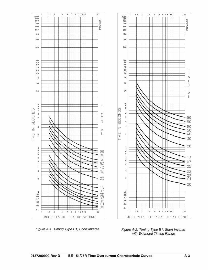
9137200999 Rev D BE1-51/27R Time Overcurrent Characteristic Curves A-3
Figure A-1. Timing Type B1, Short Inverse
Figure A-2. Timing Type B1, Short Inverse with Extended Timing Range
P00
49-0
2
1.5
P00
49-0
3
1.5

A-4 BE1-51/27R Time Overcurrent Characteristic Curves 9137200999 Rev D
Figure A-3. Timing Type B2, Long Inverse
Figure A-4. Timing Type B2, Long Inverse with Extended Timing Range
P004
9-04
P004
9-05

9137200999 Rev D BE1-51/27R Time Overcurrent Characteristic Curves A-5
Figure A-5. Timing Type B3, Definite Time
Figure A-6. Timing Type B3, Definite Time with Extended Timing Range
P00
49-0
6
P00
49-0
7

A-6 BE1-51/27R Time Overcurrent Characteristic Curves 9137200999 Rev D
Figure A-7. Timing Type B4, Moderately Inverse
Figure A-8. Timing Type B4, Moderately Inverse with Extended Timing Range
P00
49-0
8
P004
9-09

9137200999 Rev D BE1-51/27R Time Overcurrent Characteristic Curves A-7
Figure A-9. Timing Type B5, Inverse
Figure A-10. Timing Type B5, Inverse with Extended Timing Range
P00
49-1
0
P004
9-11
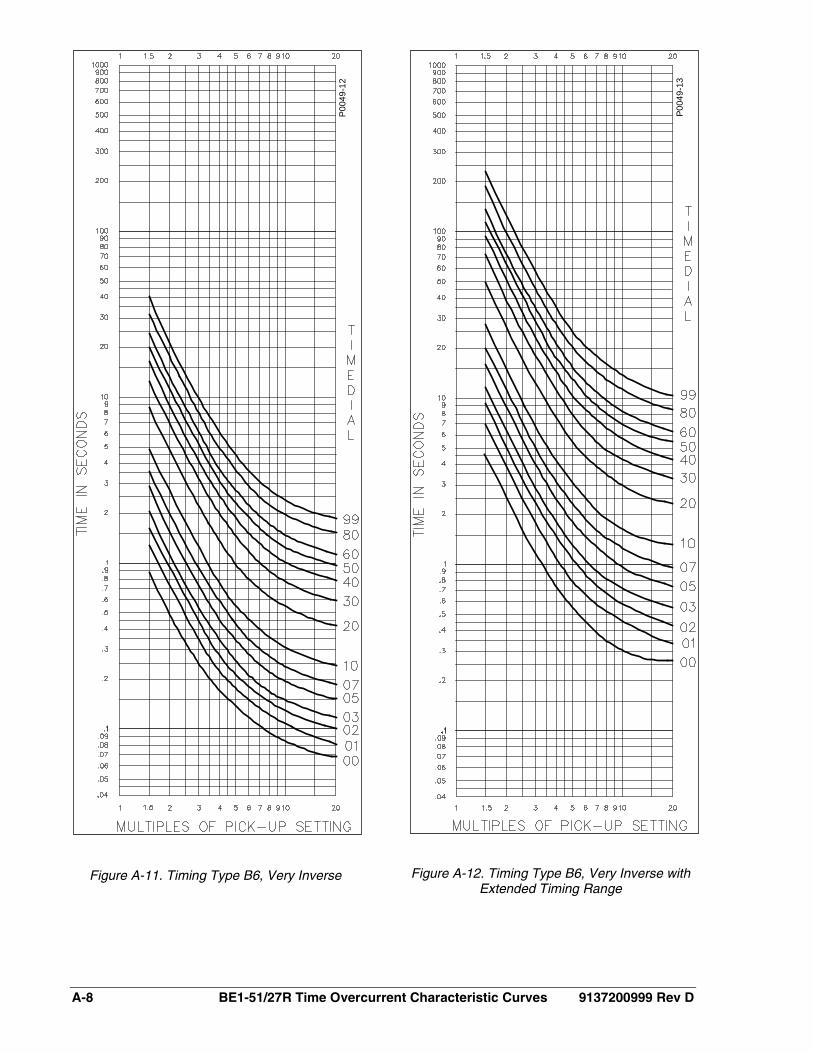
A-8 BE1-51/27R Time Overcurrent Characteristic Curves 9137200999 Rev D
Figure A-11. Timing Type B6, Very Inverse
Figure A-12. Timing Type B6, Very Inverse with Extended Timing Range
P004
9-12
P004
9-13

9137200999 Rev D BE1-51/27R Time Overcurrent Characteristic Curves A-9
Figure A-13. Timing Type B7, Extremely Inverse
Figure A-14. Timing Type B7, Extremely Inverse with Extended Timing Range
P004
9-14
P004
9-15

A-10 BE1-51/27R Time Overcurrent Characteristic Curves 9137200999 Rev D
Figure A-15. Timing Type B8, I2t
Figure A-16. Timing Type B8, I2t with Extended Timing Range
P004
9-16
P00
49-1
7

9137200999 Rev D BE1-51/27R Time Overcurrent Characteristic Curves A-11
Figure A-17. Timing Type C1, I2t with Limit #1
Figure A-18. Timing Type C1, I2t with Limit #1 and Extended Timing Range
P00
49-1
8
P00
49-1
9

A-12 BE1-51/27R Time Overcurrent Characteristic Curves 9137200999 Rev D
Figure A-19. Timing Type C2, I2t with Limit #2
Figure A-20. Timing Type C2, I2t with Limit #2 and Extended Timing Range
P00
49-2
0
P00
49-2
1

9137200999 Rev D BE1-51/27R Time Overcurrent Characteristic Curves A-13
Figure A-21. Timing Type C3, I2t with Limit #3
Figure A-22. Timing Type C3, I2t with Limit #3 and Extended Timing Range
P00
49-2
2
P004
9-23

A-14 BE1-51/27R Time Overcurrent Characteristic Curves 9137200999 Rev D
Figure A-23. Timing Type C4, I2t with Limit #4
Figure A-24. Timing Type C4, I2t with Limit #4 and Extended Timing Range
P00
49-2
4
P00
49-2
5

9137200999 Rev D BE1-51/27R Time Overcurrent Characteristic Curves A-15
Figure A-25. Timing Type C5, I2t with Limit #5
Figure A-26. Timing Type C5, I2t with Limit #5 and Extended Timing Range
P00
49-2
6
P004
9-27

A-16 BE1-51/27R Time Overcurrent Characteristic Curves 9137200999 Rev D
Figure A-27. Timing Type C6, I2t with Limit #6
Figure A-28. Timing Type C6, I2t with Limit #6 and Extended Timing Range
P004
9-28
P004
9-29

9137200999 Rev D BE1-51/27R Time Overcurrent Characteristic Curves A-17
Figure A-29. Timing Type C7, I2t with Limit #7
Figure A-30. Timing Type C7, I2t with Limit #7 and Extended Timing Range
P004
9-30
P004
9-31
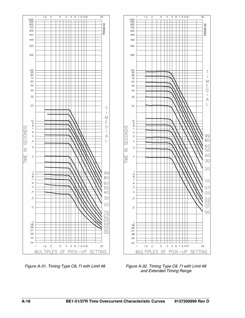
A-18 BE1-51/27R Time Overcurrent Characteristic Curves 9137200999 Rev D
Figure A-31. Timing Type C8, I2t with Limit #8
Figure A-32. Timing Type C8, I2t with Limit #8 and Extended Timing Range
P00
49-3
2
P004
9-33

9137200999 Rev D BE1-51/27R Time Overcurrent Characteristic Curves A-19
Figure A-33. Timing Type E2, BS 142 Long Inverse
Figure A-34. Timing Type E4, BS 142 Inverse
P004
9-34
P00
49-3
5

A-20 BE1-51/27R Time Overcurrent Characteristic Curves 9137200999 Rev D
Figure A-35. Timing Type E5, BS 142 Inverse
Figure A-36. Timing Type E6, BS 142 Very Inverse
P004
9-36
P004
9-37

9137200999 Rev D BE1-51/27R Time Overcurrent Characteristic Curves A-21
Figure A-37. Timing Type E7, BS 142 Extremely Inverse
P00
49-3
8
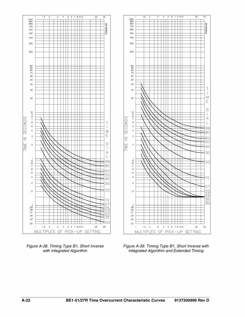
A-22 BE1-51/27R Time Overcurrent Characteristic Curves 9137200999 Rev D
Figure A-38. Timing Type B1, Short Inverse with Integrated Algorithm
Figure A-39. Timing Type B1, Short Inverse with Integrated Algorithm and Extended Timing
P00
49-3
9
P00
49-4
0

9137200999 Rev D BE1-51/27R Time Overcurrent Characteristic Curves A-23
Figure A-40. Timing Type B2, Long Inverse with Integrated Algorithm
Figure A-41. Timing Type B2, Long Inverse with Integrated Algorithm and Extended Timing
P004
9-41
P00
49-4
2

A-24 BE1-51/27R Time Overcurrent Characteristic Curves 9137200999 Rev D
Figure A-42. Timing Type B3, Definite Time with Integrated Algorithm
Figure A-43. Timing Type B3, Definite Time with Integrated Algorithm and Extended Timing
P00
49-4
3
P004
9-44

9137200999 Rev D BE1-51/27R Time Overcurrent Characteristic Curves A-25
Figure A-44. Timing Type B4, Moderately Inverse with Integrated Algorithm.
Figure A-45. Timing Type B4, Moderately Inverse with Integrated Algorithm
and Extended Timing
P00
49-4
5
P004
9-46

A-26 BE1-51/27R Time Overcurrent Characteristic Curves 9137200999 Rev D
Figure A-46. Timing Type B5, Inverse with Integrated Algorithm
Figure A-47. Timing Type B5, Inverse with Integrated Algorithm and Extended Timing
P00
49-4
7
P00
49-4
8

9137200999 Rev D BE1-51/27R Time Overcurrent Characteristic Curves A-27
Figure A-48. Timing Type B6, Very Inverse with Integrated Algorithm
Figure A-49. Timing Type B6, Very Inverse with Integrated Algorithm and Extended Timing
P00
49-4
9
P004
9-50

A-28 BE1-51/27R Time Overcurrent Characteristic Curves 9137200999 Rev D
Figure A-50. Timing Type B7, Extremely Inverse with Integrated Algorithm
Figure A-51. Timing Type B7, Extremely Inverse with Integrated Algorithm
and Extended Timing
P004
9-51
P00
49-5
2

9137200999 Rev D BE1-51/27R Time Overcurrent Characteristic Curves A-29
Figure A-52. Timing Type B8, I2t with Integrated Algorithm
Figure A-53. Timing Type B8, I2t with Integrated Algorithm and Extended Timing
P004
9-53
P00
49-5
4

A-30 BE1-51/27R Time Overcurrent Characteristic Curves 9137200999 Rev D
Figure A-54. Timing Type C1, I2t Limit #1 with Integrated Algorithm
Figure A-55. Timing Type C1, I2t Limit #1 with Integrated Algorithm
P004
9-55
P004
9-56

9137200999 Rev D BE1-51/27R Time Overcurrent Characteristic Curves A-31
Figure A-56. Timing Type C2, I2t Limit #2 with Integrated Algorithm
Figure A-57. Timing Type C2, I2t Limit #2 with Integrated Algorithm and Extended Timing
P004
9-57
P00
49-5
8

A-32 BE1-51/27R Time Overcurrent Characteristic Curves 9137200999 Rev D
Figure A-58. Timing Type C3, I2t Limit #3 with Integrated Algorithm
Figure A-59. Timing Type C3, I2t Limit #3 with Integrated Algorithm and Extended Timing
P00
49-5
9
P00
49-6
0

9137200999 Rev D BE1-51/27R Time Overcurrent Characteristic Curves A-33
Figure A-60. Timing Type C4, I2t Limit #4 with Integrated Algorithm
Figure A-61. Timing Type C4, I2t Limit #4 with Integrated Algorithm and Extended Timing
P00
49-6
1
P004
9-62

A-34 BE1-51/27R Time Overcurrent Characteristic Curves 9137200999 Rev D
Figure A-62. Timing Type C5, I2t Limit #5 with Integrated Algorithm
Figure A-63. Timing Type C5, I2t Limit #5 with Integrated Algorithm and Extended Timing
P004
9-63
P00
49-6
4

9137200999 Rev D BE1-51/27R Time Overcurrent Characteristic Curves A-35
Figure A-64. Timing Type C6, I2t Limit #6 with Integrated Algorithm
Figure A-65. Timing Type C6, I2t Limit #6 with Integrated Algorithm and Extended Timing
P004
9-65
P00
49-6
6

A-36 BE1-51/27R Time Overcurrent Characteristic Curves 9137200999 Rev D
Figure A-66. Timing Type C7, I2t Limit #7 with Integrated Algorithm
Figure A-67. Timing Type C7, I2t Limit #7 with Integrated Algorithm and Extended Timing
P00
49-6
7
P004
9-68

9137200999 Rev D BE1-51/27R Time Overcurrent Characteristic Curves A-37
Figure A-68. Timing Type C8, I2t Limit #8 with Integrated Algorithm
Figure A-69. Timing Type C8, I2t Limit #8 with Integrated Algorithm and Extended Timing
P004
9-69
P00
49-7
0

A-38 BE1-51/27R Time Overcurrent Characteristic Curves 9137200999 Rev D
This page intentionally left blank.


ROUTE 143, BOX 269
HIGHLAND, IL 62249 USA http://www.basler.com, [email protected]
PHONE +1 618-654-2341 FAX +1 618-654-2351


