77
28/01/2005 REV. 03 Sabroe Refrigeration A/S, Marine Division 1 Instruction Manual for Reciprocating Compressors SBO 21, 22, 41, 42, 43
28/01/2005 REV. 03 Sabroe Refrigeration A/S, Marine Division 1
Instruction Manual for Reciprocating Compressors
SBO 21, 22, 41, 42, 43

28/01/2005 REV. 03 Sabroe Refrigeration A/S, Marine Division 2
Preface The aim of this instruction manual is to provide the operators with a thorough knowledge of the refrigeration plant and at the same time furnishing information about: • The function and maintenance of the individual components; • Service schedules; • Procedure for dismantling and reassembling of the compressor. The instruction manual also draws attention to typical sources of error, which may occur during operations, stating their cause and explaining what should be done to rectify them. It is imperative that the operators familiarize themselves thoroughly with the contents of this instruction manual, both to ensure reliable, efficient operation and because YORK is unable to provide a guarantee against damage occurring during the warranty period if the damage is attributable to incorrect operation. The contents of this instruction manual must not be copied or passed on to any unauthorized person without the permission of YORK.
YORK MARINE YORK Refrigeration A/S Phone: +45 87 36 70 00 Christian den X's Vej 201 Fax: +45 87 36 70 05 P O Box 1810 Telex: 6 8723 DK-8270 Højbjerg Denmark Reg no 1475

28/01/2005 REV. 03 Sabroe Refrigeration A/S, Marine Division 3
Table of Contents
YORK MARINE SERVICE & PARTS..............................................................8
Service & Parts, Aarhus.........................................................................................................................8
Service & Parts, Norrköping .................................................................................................................8
Service & Parts, Hamburg.....................................................................................................................8
Service & Parts, Seattle..........................................................................................................................8
FIRST AID FOR ACCIDENTS WITH HFC/HCFC............................................9
Generally .................................................................................................................................................9 Basic Rules for First Aid .....................................................................................................................9 Inhalation.............................................................................................................................................9 Eye Troubles........................................................................................................................................9 Skin Injuries - Frost Sores ...................................................................................................................9
PROTECTING THE ENVIRONMENT............................................................11
REFRIGERANT CIRCUIT .............................................................................14
DESCRIPTION OF THE COMPRESSOR .....................................................21
SBO21 and SBO22................................................................................................................................21
SBO41, SBO42 and SBO43..................................................................................................................21
HANDLING OF COMPRESSOR, AREAS OF APPLICATION,.....................22
Direction of Rotation............................................................................................................................22
Handling of Compressor and Unit ......................................................................................................22
AREAS OF APPLICATION OF THE RECIPROCATING COMPRESSORS.23
The compressor must NOT be used:...................................................................................................23
Emergency Switch ................................................................................................................................23
VIBRATION DATA FOR THE COMPRESSORS - ALL TYPES....................24
COMPRESSOR DATA FOR RECIPROCATING COMPRESSORS .............26
SBO 21, 22, 41, 42, 43 ...........................................................................................................................26
Operating Limits ..................................................................................................................................26
Main data: .............................................................................................................................................26 SBO21 and SBO22 compressors .......................................................................................................26

28/01/2005 REV. 03 Sabroe Refrigeration A/S, Marine Division 4
SBO41, SBO42 and SBO43 compressors .........................................................................................26 Technical Data of Compressors.........................................................................................................27 SBO 21 ..............................................................................................................................................27 SBO 22 ..............................................................................................................................................27 SBO 41 ..............................................................................................................................................27 SBO 42 ..............................................................................................................................................28 Compressor Oil Charge .....................................................................................................................29 V-Belt Type .......................................................................................................................................29 Compressor Weight ...........................................................................................................................29 Cylinder Number / Bore / Stroke.......................................................................................................29
GENERAL OPERATING INSTRUCTIONS ...................................................30
Starting up Compressor and Plant .....................................................................................................30 Stopping and Starting-Up Compressor during a Short Period of Standstill.......................................31 Stopping the Plant for Brief Periods (Until 2-3 Days).......................................................................31 Stop of Condenser Cooling, Pumps, Fans and any Compressor Cooling. .........................................31 Stopping the Plant for Lengthy Periods (More than 2-3 Days) .........................................................31 Pressure Testing of Refrigeration Plant .............................................................................................32 Pumping Down of the Refrigeration Plant.........................................................................................33
OPERATING LOG.........................................................................................35
SERVICING THE RECIPROCATING COMPRESSOR .................................36
Removing Refrigerant from the Compressor ....................................................................................36
SCHEDULED SERVICES .............................................................................37
LUBRICATING OIL .......................................................................................40
Lubricating Oil Requirements ............................................................................................................40
Charging Refrigeration Compressor with Lubricating Oil ..............................................................41
EXPECTED DISCHARGE GAS TEMPERATURES......................................42
MAINTENANCE OF SBO RECIPROCATING COMPRESSORS..................43
Generally ...............................................................................................................................................43 Pump-Down.......................................................................................................................................43
The Compressor is Operational ..........................................................................................................43
The Compressor is Inoperative ...........................................................................................................44
Dismantling and Assembly ..................................................................................................................44
Valve Intermediate Plate .....................................................................................................................44
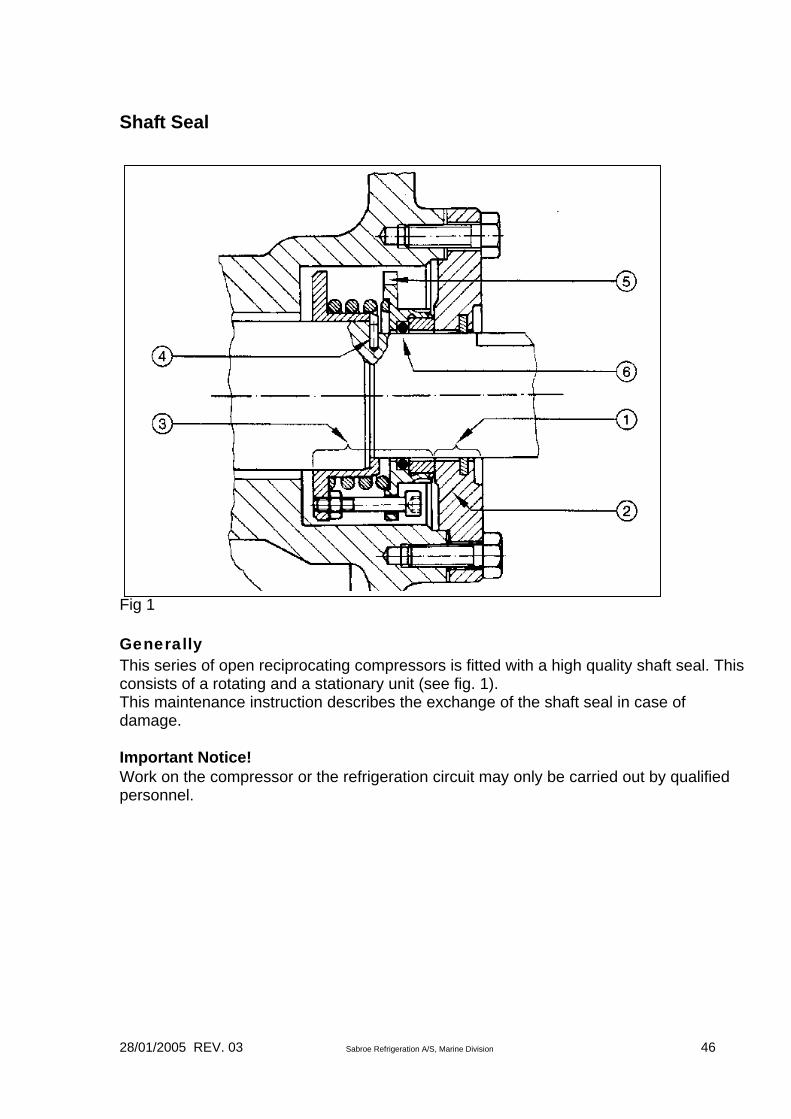
SHAFT SEAL ................................................................................................46
Generally ...............................................................................................................................................46 Important Notice!...............................................................................................................................46
28/01/2005 REV. 03 Sabroe Refrigeration A/S, Marine Division 5
Inspection ..............................................................................................................................................47
POSSIBLE CAUSES OF FAILURE ..............................................................47
Removal.................................................................................................................................................47 Preparation & Recommendations ......................................................................................................47 Removing the Shaft Seal ...................................................................................................................47
Fitting ....................................................................................................................................................48 Preparation & Recommendations ......................................................................................................48 Special Recommendations.................................................................................................................48
Fitting the Shaft Seal ............................................................................................................................48
CLEANING OF OIL FILTER..........................................................................49
SUCTION FILTER .........................................................................................49
STOP VALVES..............................................................................................50
CAPACITY REGULATION FOR COMPRESSOR SBO41, SBO42 AND SBO43 ...........................................................................................................50
Function.................................................................................................................................................50
START UNLOADING ....................................................................................52
Integrated start unloading:..................................................................................................................52
Externally mounted start unloading:..................................................................................................53
HEATING RODS FOR OIL HEATING...........................................................54
Note:.......................................................................................................................................................54
TORQUE MOMENTS FOR SCREWS AND BOLTS .....................................55
REFRIGERATION PLANT MAINTENANCE.................................................56
Operational Reliability.........................................................................................................................56
Pumping Down the Refrigeration Plant .............................................................................................56
DISMANTLING PLANT .................................................................................57
LEAK TESTING AND PUMP-DOWN OF REFRIGERATION PLANT...........57
TROUBLE-SHOOTING ON THE RECIPROCATING COMPRESSOR PLANT.......................................................................................................................58

28/01/2005 REV. 03 Sabroe Refrigeration A/S, Marine Division 6
Operating Conditions...........................................................................................................................58
Using the trouble-shooting chart.........................................................................................................58 Example .............................................................................................................................................58
REMEDYING MALFUNCTIONS....................................................................61
1. Compressor fails to start:................................................................................................................61
2. Compressor starts and stops too often: .........................................................................................61
3. Compressor starts, but stops again immediately:.........................................................................62
4. Compressor operates continuously:...............................................................................................63
5. Abnormal noise from compressor:.................................................................................................63
6. Too little capacity on compressor: .................................................................................................64
7. Slugging in compressor during start-up:.......................................................................................64
8. Slugging in compressor during operation: ....................................................................................64
9. Excessive condenser pressure:........................................................................................................65
10. Too low condenser pressure: ........................................................................................................65
11. Excessive suction pressure:...........................................................................................................66
12. Too low suction pressure: .............................................................................................................66
13. Oil temperature too low:...............................................................................................................67
14. Excessive discharge pipe temperature:........................................................................................67
15. Too low discharge pipe temperature: ..........................................................................................67
16. Excessive oil temperature: ............................................................................................................68
17. Oil level in crankcase falling: .......................................................................................................68
18. Heavy oil foaming in crankcase: ..................................................................................................69
19. Crankcase "sweating" or frosting up: .........................................................................................69
20. Capacity regulation oscillating:....................................................................................................69
21. Impossible to bleed plant: .............................................................................................................69
ALIGNMENT OF UNIT ..................................................................................70
Alignment of Compressor with Base Frame ......................................................................................70
Alignment of Motor with Base Frame ................................................................................................70
Stresses from Pipe Connections...........................................................................................................70
28/01/2005 REV. 03 Sabroe Refrigeration A/S, Marine Division 7
V-BELT DRIVE FOR SBO RECIPROCATING COMPRESSORS.................71
Mounting of V-belts..............................................................................................................................71 Remember:.........................................................................................................................................71
ORDERING OF SPARE PARTS ...................................................................72
Spare part drawing for compressor type SBO21 and SBO22 ..........................................................73
Spare part drawing for compressor type SBO41, SBO42, SBO43...................................................74
Spare parts list for compressor type SBO ..........................................................................................75

28/01/2005 REV. 03 Sabroe Refrigeration A/S, Marine Division 8
YORK Marine Service & Parts Service & Parts, Aarhus YORK Marine Phone +45 87 36 35 00 Jens Juuls Vej 28 Fax +45 87 36 35 01 8260 Viby J 24-hour service line Denmark Service & Parts, Norrköping YORK Marine AB Phone +46 11 21 45 00 P O Box 667 Fax +46 11 10 29 81 Lindåkersgatan 2 24-hour service line 601 15 Norrköping +46 10 20 04 42 Sweden Service & Parts, Hamburg YORK Marine Hamburg Phone +49 40 6 70 51150 Kiebitzhörn 33-35 Fax +49 40 6 70 1216 22885 Barsbüttel Germany
Service & Parts, Seattle YORK Marine Seattle Phone +1 206 285 0904 4401 23rd Ave. West Fax +1 206 285 0965 Seattle, WA 98199 24-hour service line USA +1 206 818 3160
Service & Parts, Singapore YORK Marine Singapore Phone +65 28 457 22 No 10 Upper Aljunied Link 08-00 Fax +65 28 692 43 YORK Industrial Building 367904 Singapore

28/01/2005 REV. 03 Sabroe Refrigeration A/S, Marine Division 9
First Aid for Accidents with HFC/HCFC Refrigerant Nos.: R22 - R134a - R404A - R507 - R407C, etc. Generally HFC/HCFC form colourless and invisible gasses, which are heavier than air and smell faintly of chloroform at high concentrations only. Under normal operating conditions they are non-toxic, non-inflammable, non-explosive and non-corrosive. When heated to above approx. 300°C they break down into toxic, acid gas components, which are strongly irritating and aggressive to nose, eyes and skin and generally corrosive. Besides the obvious risk of unnoticeable, heavy gases displacing the atmospheric oxygen, inhalation of larger concentrations may have an accumulating, anaesthetic effect which may not be immediately apparent. 24 hours medical observations are, therefore, recommended. Basic Rules for First Aid 1. When moving affected persons from low-lying or poorly ventilated rooms
where high gas concentrations are suspected, the rescuer must be wearing a lifeline, and be under continuous observation from an assistant outside the room.
2. Adrenaline or similar heart stimuli must not be used. Inhalation 1. Move the affected person into fresh air immediately. Keep the patient still
and warm and loosen clothing restricting breathing.
2. If the patient is unconscious, immediately call a doctor/ambulance with oxygen equipment.
3. Administer artificial respiration until a doctor authorizes other treatment. Eye Troubles 1. Force eyelids open and rinse with a sterile isotonic (0.9%) NaCl-solution
(salt water) or pure running water continuously for 30 minutes.
2. Contact a doctor, or get the patient to a hospital immediately for medical advice.
Skin Injuries - Frost Sores 1. Wash immediately with large quantities of lukewarm water to reheat the
skin. Continue for at least 15 minutes, removing contaminated clothing carefully while washing.
2. Treat exactly like burns and seek medical advice.

28/01/2005 REV. 03 Sabroe Refrigeration A/S, Marine Division 10
3. Avoid direct contact with contaminated oil/refrigerant mixtures from electrically burnt-out hermetic compressors.
No plant can ever be said to be too safe. Safety is a way of life.

28/01/2005 REV. 03 Sabroe Refrigeration A/S, Marine Division 11
Protecting the Environment Increasing industrialisation threatens our environment. It is therefore absolutely imperative that we protect nature against pollution. To this end, many countries have passed legislation in an effort to reduce pollution and preserve the environment. These laws apply to all fields of industry, including refrigeration, and must be obeyed. Be especially careful with the following substances: • refrigerants • cooling media (brines etc) • lubricating oils. Refrigerants usually have a natural boiling point, which lies far below 0°C. This means that liquid refrigerants can be extremely harmful if they come into contact with skin or eyes. High concentrations of refrigerant vapours are suffocating when they displace air; and if high concentrations of refrigerant vapours are inhaled they will attack the human nervous system. When halogenated gasses come into contact with open flame or hot surfaces (over approx. 300°C) they decompose to produce poisonous chemicals, which have a very pungent odour, warning you of their presence. In high concentrations, R717 causes respiratory problems, and when ammonia vapour and air mix 15 to 28 vol. %, the combination is explosive and can be ignited by an electric spark or open flame. Oil vapour in the ammonia vapour increases this risk significantly as the point of ignition falls below that of the mixture ratio stated. Usually the strong smell of ammonia will give ample warning of its presence before concentrations become dangerous. The following table shows the values for refrigerant content in air, measured in volume %. Certain countries may, however, have an official limit, which differs from the one stated.

28/01/2005 REV. 03 Sabroe Refrigeration A/S, Marine Division 12
Halogenated Refrigerants Ammonia R134a R404A R507 R22 R717 Unit TWA Time weighted average during a week
vol. %
0.1
0.1
0.1
0.1
0.005
Warning smell
vol. %
0.2
0.002
28/01/2005 REV. 03 Sabroe Refrigeration A/S, Marine Division 13
Further, it may be said about refrigerants: • If halogenated refrigerants are released directly to the atmosphere they will
break down the ozone layer in the stratosphere. The ozone layer protects the earth from the ultraviolet radiation of the sun. Halogenated refrigerants must, therefore, never be released to the atmosphere. Use a separate compressor to draw the refrigerant into the plant’s condenser/receiver or into separate refrigerant cylinders.
• Most halogenated refrigerants are miscible with oil. Oil drained from a refrigeration plant will often contain significant amounts of refrigerant. Therefore, reduce the pressure in the vessel or compressor as much as possible before draining the oil.
Refrigerant evacuated from a refrigerant plant shall be charged into refrigerant cylinders intended for this specific refrigerant. If the refrigerant is not to be re-used, return it to the supplier or to an authorized refuse disposal plant. Halogenated refrigerants must never be mixed. Purging a Refrigeration Plant If it is necessary to purge air from a refrigeration plant, make sure you observe the following: • Refrigerants must not be released to the atmosphere.
• Halogenated refrigerants cannot be absorbed by water. An approved air
purger must be fitted to the plant. This must be checked regularly using a leak detector.

28/01/2005 REV. 03 Sabroe Refrigeration A/S, Marine Division 14
Refrigerant Circuit Source: Danfoss. Refrigeration - An Introduction to the Basics No. RG.00.E1.02
A simple refrigerant circuit is built up as shown in the sketch below. In what follows, the individual components are described to clarify a final overall picture. Evaporator A refrigerant in liquid form will absorb heat when it evaporates and it is this conditional change that produces cooling in a refrigerating process. If a refrigerant at the same temperature as the ambient is allowed to expand through a hose with an outlet to atmospheric pressure, heat will be taken up from the surrounding air and evaporation will occur at a temperature corresponding to atmospheric pressure. If in a certain situation pressure on the outlet side (atmospheric pressure) is changed, a different temperature will be obtained since this is analogous to the original temperature - it is pressure-dependent.
The component where this occurs is the evaporator, the job of which is to remove heat from the surroundings, i.e. to produce refrigeration.

28/01/2005 REV. 03 Sabroe Refrigeration A/S, Marine Division 15
Compressor The refrigeration process is, as implied, a closed circuit. The refrigerant is not allowed to expand to free air. When the refrigerant coming from the evaporator is fed to a tank the pressure in the tank will rise until it equals the pressure in the evaporator. Therefore, refrigerant flow will cease and the temperature in both tank and evaporator will gradually rise to ambient. To maintain a lower pressure, and, with it a lower temperature it is necessary to remove vapour. This is done by the compressor, which sucks vapour away from the evaporator. In simple terms, the compressor can be compared to a pump that conveys vapour in the refrigerant circuit. In a closed circuit a condition of equilibrium will always prevail. To illustrate this, if the compressor sucks vapour away faster than it can be formed in the evaporator the pressure will fall and with it the temperature in the evaporator. Conversely, if the load on the evaporator rises and the refrigerant evaporates quicker, the pressure and with it the temperature in the evaporator will rise.

28/01/2005 REV. 03 Sabroe Refrigeration A/S, Marine Division 16
Compressor, Method of Operation Refrigerant leaves the evaporator either as saturated or weakly superheated vapour and enters the compressor where it becomes compressed. Compression is carried out as in a petrol engine, i.e. by the movement of a piston. The compressor requires energy and does work. This work is transferred to the refrigerant vapour and is called the compression input. Because of the compression input, vapour leaves the compressor at a different pressure and the extra energy applied causes strong superheating of the vapour. Compression input is dependent on plant pressure and temperature. More work is of course required to compress 1 kg vapour 10 at (~ bar) than to compress the same amount 5 at (~ bar). Condenser The refrigerant gives off heat in the condenser, and that heat is transferred to a medium having a lower temperature. The amount of heat given off is the heat absorbed by the refrigerant in the evaporator plus the heat created by compression input.

28/01/2005 REV. 03 Sabroe Refrigeration A/S, Marine Division 17
The heat transfer medium can be air or water, the only requirement being that the temperature is lower than that which corresponds to the condensing pressure. The process in the condenser can otherwise be compared with the process in the evaporator except that it has the opposite ”sign”, i.e. the conditional change is from vapour to liquid. Expansion Process Liquid from the condenser runs to a collecting tank, the receiver. This can be likened to the tank mentioned under paragraph 3.1 on the evaporator. The pressure in the receiver is much higher than the pressure in the evaporator because of the compression (pressure increase) that has occurred in the compressor. To reduce pressure to the same level as the evaporating pressure a device must be inserted to carry out this process, which is called throttling or expansion. Such a device is therefore known either as a throttling device or an expansion device. As a rule a valve is used - a throttle or expansion valve. Ahead of the expansion valve the liquid will be a little under boiling point. By suddenly reducing pressure a conditional change will occur; the liquid begins to boil and evaporate. This evaporation takes place in the evaporator and the circuit is thus complete.

28/01/2005 REV. 03 Sabroe Refrigeration A/S, Marine Division 18
High and Low Pressure Sides of the Refrigeration Plant There are many different temperatures involved in the operation of a refrigeration plant since there are such things as subcooled liquid, saturated liquid, saturated vapour and superheated vapour. There are however, in principle, only two pressures: evaporating pressure and condensing pressure. The plant then is divided into high pressure and low pressure sides, as shown in the sketch. Refrigeration Process, Pressure/Enthalpy Diagram The condensed refrigerant in the receiver is in condition A, which lies on the line for the boiling point of the liquid. The liquid has thus a temperature tk (condensing temperature), a pressure pk (condensing pressure) and an enthalpy ho. When the liquid passes through the expansion valve its condition changes from A to B. This conditional change is brought about by the liquid boiling because of the drop in pressure to po. At the same time a lower boiling point is

28/01/2005 REV. 03 Sabroe Refrigeration A/S, Marine Division 19
produced, to, because of the drop in pressure. At the expansion valve, as heat is neither applied nor removed, the enthalpy is still ho. At the evaporator inlet there is a mixture of liquid and vapour while at the evaporator outlet point C is saturated vapour. Pressure and temperature are the same at point B, but since the evaporator has absorbed heat from the surroundings the enthalpy has changed to h1. When the refrigerant passes through the compressor its condition changes from C to D. Pressure rises to condensing pressure pk. The temperature rises to tov, which is higher than the condensing temperature tk, because the vapour has been strongly superheated. More energy in the form of heat has also been introduced and the enthalpy therefore changes to h2. At the condenser inlet, point D, the condition is thus one of superheated vapour at pressure pk. Heat is given off from the condenser to the surroundings so that the enthalpy again changes to main point A. First in the condenser there occurs a conditional change from strongly superheated vapour to saturated vapour (point E) then a condensation of the saturated vapour. From point E to point A the temperature (condensing temperature) remains the same, because condensation and evaporation occur at a constant temperature. In practice the refrigerating process will appear slightly differently in a pressure/enthalpy diagram because normally less superheating of the vapour from the evaporator occurs and the liquid temperature ahead of the expansion valve can be weakly subcooled because of the heat exchange with the surroundings.
28/01/2005 REV. 03 Sabroe Refrigeration A/S, Marine Division 20
Lubricating Oils Refrigeration compressors are lubricated by one of the following oil types, depending on the refrigerant, plant type and operating conditions: - semi-synthetic oil - alkyl benzene-based synthetic oil - polyalphaolefin-based synthetic oil - glycol-based synthetic oil. When you change the oil in the compressor or drain oil from the vessels of the refrigeration plant, always collect the used oil in containers marked “waste oil” and send them to an approved refuse disposal plant. Note: This instruction provides general information only. The owner of the refrigeration plant is responsible for ensuring that all by-laws are complied with.
28/01/2005 REV. 03 Sabroe Refrigeration A/S, Marine Division 21
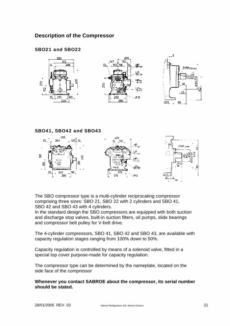
Description of the Compressor SBO21 and SBO22
SBO41, SBO42 and SBO43
The SBO compressor type is a multi-cylinder reciprocating compressor comprising three sizes: SBO 21, SBO 22 with 2 cylinders and SBO 41, SBO 42 and SBO 43 with 4 cylinders. In the standard design the SBO compressors are equipped with both suction and discharge stop valves, built-in suction filters, oil pumps, slide bearings and compressor belt pulley for V-belt drive. The 4-cylinder compressors, SBO 41, SBO 42 and SBO 43, are available with capacity regulation stages ranging from 100% down to 50%. Capacity regulation is controlled by means of a solenoid valve, fitted in a special top cover purpose-made for capacity regulation. The compressor type can be determined by the nameplate, located on the side face of the compressor Whenever you contact SABROE about the compressor, its serial number should be stated.
28/01/2005 REV. 03 Sabroe Refrigeration A/S, Marine Division 22
Handling of Compressor, Areas of Application, Direction of Rotation On the SBO compressors the direction of rotation is not indicated by an arrow, but is standard clockwise - seen from shaft end Handling of Compressor and Unit For lifting of the compressor the models are equipped with lifting eyes. As to the weight of the compressor, see table on compressor data. Note: The compressor block alone may be lifted in the lifting eyes. The same applies to the motor. The unit is lifted by catching the lifting eyes on the unit frame. These have been clearly marked with red paint.
28/01/2005 REV. 03 Sabroe Refrigeration A/S, Marine Division 23
Areas of Application of the Reciprocating Compressors Compressor Types: SBO 21, 22, 41, 42, 43 In view of preventing an unintended application of the compressor, which could cause injuries to the operating staff or lead to technical damage, the compressors may only be applied for the following purposes: The compressor may ONLY be used: • As a refrigeration compressor with a number or revolutions and with
operating limits as indicated in this manual or according to a written agreement with SABROE.
• With the following refrigerants: R22-R134a-R404A-R507-R407C
• All other types of gas may only be used following a written approval from SABROE.
The compressor must NOT be used: • For evacuating the refrigeration plant of air and moisture, • For putting the refrigeration plant under air pressure in view of a pressure
testing, • As an air compressor. Emergency Switch The compressor control system must be equipped with an emergency switch. In case the compressor is delivered with a SABROE control system this emergency switch is found as an integrated part of the control. The emergency heigh-pressure switch must be executed in a way to make it stay in its stopped position, following a stop instruction, until it is manually set back again. It must not be possible to block the emergency stop without a stop instruction being released. The emergency low-pressure switch is automatically reset.
28/01/2005 REV. 03 Sabroe Refrigeration A/S, Marine Division 24
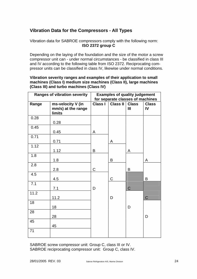
Vibration Data for the Compressors - All Types Vibration data for SABROE compressors comply with the following norm:
ISO 2372 group C Depending on the laying of the foundation and the size of the motor a screw compressor unit can - under normal circumstances - be classified in class III and IV according to the following table from ISO 2372. Reciprocating com-pressor units can be classified in class IV, likewise under normal conditions. Vibration severity ranges and examples of their application to small machines (Class I) medium size machines (Class II), large machines (Class III) and turbo machines (Class IV) Ranges of vibration severity Examples of quality judgement
for separate classes of machines Range ms-velocity V (in
mm/s) at the range limits
Class I Class II Class III
Class IV
0.28
0.28
0.45
0.45
A
0.71
0.71
A
1.12
1.12
B
A
1.8
1.8
B
A
2.8
2.8
C
B
4.5
4.5
C
B
7.1
7.1
D
C
11.2
11.2
D
C
18
18
D
28
28
D
45
45
71
SABROE screw compressor unit: Group C, class III or IV. SABROE reciprocating compressor unit: Group C, class IV.

28/01/2005 REV. 03 Sabroe Refrigeration A/S, Marine Division 25
Pay attention to the following, however: • On placing the unit on the vibration dampers delivered by SABROE
(additionally) the vibrations against the foundation are reduced by: - 80% for reciprocating compressor units
• However, a higher vibration level may occur if: Motor and compressor have not been aligned as described in the Instruction Manual. The pipe connections have been executed in a way that makes them force pull or push powers on the compressor unit or they may transfer vibrations to the unit, caused by natural vibrations or connected machinery. The vibration dampers have not been fitted or loaded correctly as indicated on the foundation drawing delivered together with the order.

28/01/2005 REV. 03 Sabroe Refrigeration A/S, Marine Division 26
Compressor Data for Reciprocating Compressors SBO 21, 22, 41, 42, 43 Operating Limits SABROE prescribes certain operating limits within which compressor and any additional equipment should be operating. These operating limits for R22 and R134a as well as the main data of the compressor are stated in the following tables and diagrams. Main data: SBO21 and SBO22 compressors
SBO41, SBO42 and SBO43 compressors
28/01/2005 REV. 03 Sabroe Refrigeration A/S, Marine Division 27
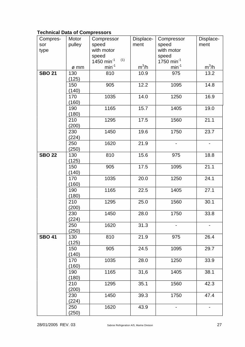
Technical Data of Compressors Compres-sor type
Motor pulley
Compressor speed with motor speed 1450 min-1 (1)
Displace-ment
Compressor speed with motor speed 1750 min-1
Displace- ment
ø mm min-1 m3/h min-1 m3/h 130 (125)
810 10.9 975 13.2
150 (140)
905 12.2 1095 14.8
SBO 21
170 (160)
1035 14.0 1250 16.9
190 (180)
1165 15.7 1405 19.0
210 (200)
1295 17.5 1560 21.1
230 (224)
1450 19.6 1750 23.7
250 (250)
1620 21.9 - -
SBO 22 130 (125)
810 15.6 975 18.8
150 (140)
905 17.5 1095 21.1
170 (160)
1035 20.0 1250 24.1
190 (180)
1165 22.5 1405 27.1
210 (200)
1295 25.0 1560 30.1
230 (224)
1450 28.0 1750 33.8
250 (250)
1620 31.3 - -
SBO 41 130 (125)
810 21.9 975 26.4
150 (140)
905 24.5 1095 29.7
170 (160)
1035 28.0 1250 33.9
190 (180)
1165 31,6 1405 38.1
210 (200)
1295 35.1 1560 42.3
230 (224)
1450 39.3 1750 47.4
250 (250)
1620 43.9 - -
28/01/2005 REV. 03 Sabroe Refrigeration A/S, Marine Division 28
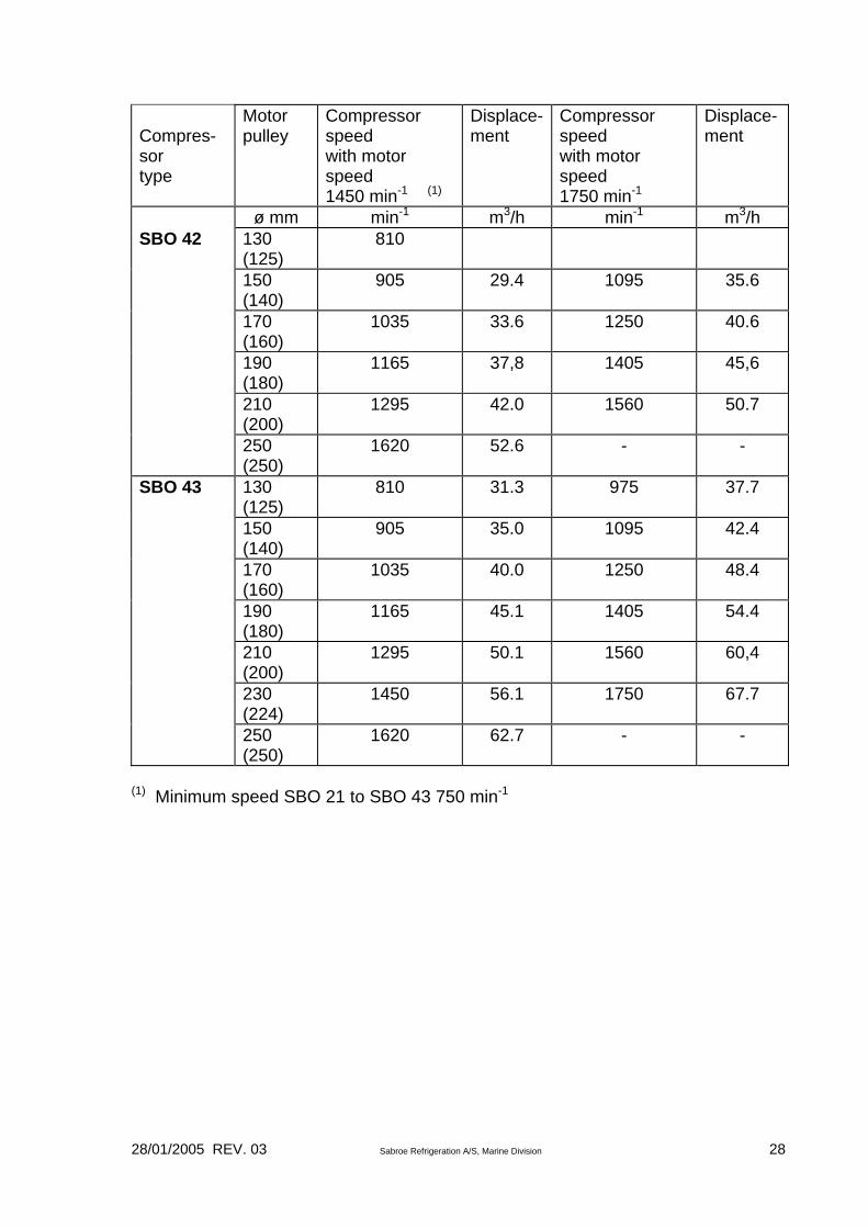
Compres-sor type
Motor pulley
Compressor speed with motor speed 1450 min-1 (1)
Displace-ment
Compressor speed with motor speed 1750 min-1
Displace- ment
ø mm min-1 m3/h min-1 m3/h SBO 42 130
(125) 810
150 (140)
905 29.4 1095 35.6
170 (160)
1035 33.6 1250 40.6
190 (180)
1165 37,8 1405 45,6
210 (200)
1295 42.0 1560 50.7
250 (250)
1620 52.6 - -
SBO 43 130 (125)
810 31.3 975 37.7
150 (140)
905 35.0 1095 42.4
170 (160)
1035 40.0 1250 48.4
190 (180)
1165 45.1 1405 54.4
210 (200)
1295 50.1 1560 60,4
230 (224)
1450 56.1 1750 67.7
250 (250)
1620 62.7 - -
(1) Minimum speed SBO 21 to SBO 43 750 min-1
28/01/2005 REV. 03 Sabroe Refrigeration A/S, Marine Division 29
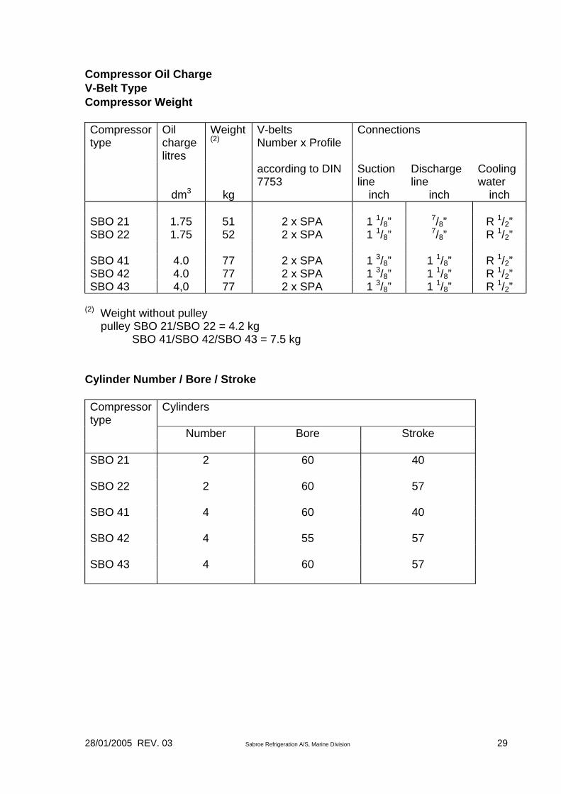
Compressor Oil Charge V-Belt Type Compressor Weight Compressor type
Oil charge litres
Weight (2)
V-belts Number x Profile
Connections
according to DIN 7753
Suction line
Discharge line
Cooling water
dm3 kg inch inch inch SBO 21 1.75 51 2 x SPA 1 1/8” 7/8” R 1/2” SBO 22 1.75 52 2 x SPA 1 1/8” 7/8” R 1/2” SBO 41 4.0 77 2 x SPA 1 3/8” 1 1/8” R 1/2” SBO 42 4.0 77 2 x SPA 1 3/8” 1 1/8” R 1/2” SBO 43 4,0 77 2 x SPA 1 3/8” 1 1/8” R 1/2”
(2) Weight without pulley pulley SBO 21/SBO 22 = 4.2 kg SBO 41/SBO 42/SBO 43 = 7.5 kg Cylinder Number / Bore / Stroke Compressor type
Cylinders
Number Bore Stroke SBO 21 2 60 40 SBO 22 2 60 57 SBO 41 4 60 40 SBO 42 4 55 57 SBO 43 4 60 57

28/01/2005 REV. 03 Sabroe Refrigeration A/S, Marine Division 30
General Operating Instructions for SBO 21, 22, 41, 42, 43 Reciprocating Compressors Starting up Compressor and Plant • The heating rod in the crankcase must be energized at least 12 hours
before starting up the compressor in order to boil any refrigerant out of the compressor oil. At the same time, the suction stop valve must be open.
• Check oil level in crankcase. The oil level must always be visible in the oil sight glass. See section: Charging the compressor with oil.
• Check correct setting of safety automatics on compressor.
• Open discharge stop valve at compressor.
• Set capacity regulator at minimum capacity. (Not standard.)
• In order to avoid excessive pressure reduction in the compressor on start-up, the suction stop valve must be opened a few turns, as there is otherwise a risk of oil foaming in the crankcase.
• Open all other stop valves except for the main valve in the liquid line and possible by-pass valves serving other purposes. Start condenser cooling, brine pumps, fans at air coolers as well as any compressor cooling device. (All of this is usually done automatically)
Note: If oil separator is used and the oil separator at standstill is colder than the condenser, the valve in the oil return pipe must not be opened until the oil separator has warmed up. • Start compressor motor and check suction and oil pressures.
• Carefully continue opening suction stop valve to its full open position.
• Open main valve in liquid line.
• If the oil in the crankcase foams, or knocking sounds are heard from the
compressor because droplets of liquid are being fed in with the suction gas, immediately throttle suction stop valve.
• The compressor is now operating. Increase capacity stepwise, allowing the compressor to adjust to new conditions before switching to next stage. Check carefully whether oil is foaming and whether oil pressure is correct.
28/01/2005 REV. 03 Sabroe Refrigeration A/S, Marine Division 31
• Check whether oil return from oil separator is working, the pipe should normally be warm. (If oil separator mounted)
• Do not leave the plant for the first 15 minutes after start-up and never
before it has stabilized.
Stopping and Starting-Up Compressor during a Short Period of Standstill Before stopping the compressor, its capacity must be reduced to the lowest capacity stage for a few minutes, before it stops. (Capacity regulating is not standard.) During short periods of standstill, it is not necessary to shut off the suction stop valve and the discharge stop valve. The heating rod must be energized. Compressor start-up must always take place at the lowest capacity stage, after which capacity is increased at suitable intervals, in order to avoid that a sudden excessive pressure reduction in the evaporation system causes slugging in the compressor and oil foaming in the crankcase. Stopping the Plant for Brief Periods (Until 2-3 Days) • Shut-off liquid supply to evaporators for a few minutes before stopping the
plant.
• Stop compressor and shut-off suction and discharge stop valves. Close valve in oil return.
Stop of Condenser Cooling, Pumps, Fans and any Compressor Cooling. • Cut-off power supply to both master and control currents. Stopping the Plant for Lengthy Periods (More than 2-3 Days) • Shut-off main valve after receiver and pump down evaporators. If
necessary, adjust low-pressure cut-out on unit to a lower pressure during evacuation.
• Allow temperature in evaporators to rise, then repeat evacuation.
• When suction pressure has been reduced to slightly over atmospheric pressure, stop compressor. Shut-off suction and discharge stop valves and close-off stop valve in oil return.
• Shut-off condenser cooling. If there is a risk of freezing, draw-off coolant.
28/01/2005 REV. 03 Sabroe Refrigeration A/S, Marine Division 32
• Cut-off power supply to master and control currents.
• Inspect receiver, condenser and pressure vessels as well as piping connections and apparatus for leakage.
Pressure Testing of Refrigeration Plant Before charging the plant with refrigerant, it must be pressure tested and pumped down. Pressure test the plant with one of the following means: • dry air - pressurized cylinders containing dry atmospheric air may be used
- but never oxygen cylinders;
• air compressor for high pressure;
• nitrogen. Important The plant compressors must not be used to pressurize the plant. Water or other fluids must not be used for pressure testing. If nitrogen is used, it is important to place a reducing valve with a pressure gauge between the nitrogen cylinder and the plant. During pressure testing, it is important to ensure that pressure transducers and other control equipment are not exposed to the testing pressure. The compressor stop valves must also be closed during pressure testing. Plant safety valves must normally be blanked-off during pressure testing, as their opening pressure is lower than the testing pressure. Important During this pressure testing, no person should be allowed to be present in rooms housing plant parts or in the vicinity of the plant outside the rooms. • The entire unit must be pressure tested in accordance with the local
regulations for pressure testing.
• The test pressure must never exceed the design pressure.
• If it is required that the compressor should be pressure tested together with the unit or with the plant, the testing pressure must not exceed: For reciprocating compressors: SBO: 25 bar
28/01/2005 REV. 03 Sabroe Refrigeration A/S, Marine Division 33
• Please observe that manometers, pressure controls, pressure transmitters and other control equipment are not exposed to testing pressure.
• Afterwards, reduce the pressure to 10 bar for a period of 24 hours - for an initial leak test - as a tightly sealed plant will maintain this pressure throughout the period.
During the leak test, it is permitted to enter the room and approach the plant. • By way of a second leak test, examine all welds, flange joints etc. for
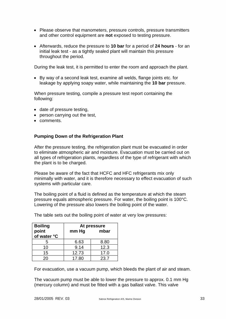
leakage by applying soapy water, while maintaining the 10 bar pressure. When pressure testing, compile a pressure test report containing the following: • date of pressure testing, • person carrying out the test, • comments. Pumping Down of the Refrigeration Plant After the pressure testing, the refrigeration plant must be evacuated in order to eliminate atmospheric air and moisture. Evacuation must be carried out on all types of refrigeration plants, regardless of the type of refrigerant with which the plant is to be charged. Please be aware of the fact that HCFC and HFC refrigerants mix only minimally with water, and it is therefore necessary to effect evacuation of such systems with particular care. The boiling point of a fluid is defined as the temperature at which the steam pressure equals atmospheric pressure. For water, the boiling point is 100°C. Lowering of the pressure also lowers the boiling point of the water. The table sets out the boiling point of water at very low pressures: Boiling point of water °C
At pressure mm Hg mbar
5 6.63 8.80 10 9.14 12.3 15 12.73 17.0 20 17.80 23.7 For evacuation, use a vacuum pump, which bleeds the plant of air and steam. The vacuum pump must be able to lower the pressure to approx. 0.1 mm Hg (mercury column) and must be fitted with a gas ballast valve. This valve
28/01/2005 REV. 03 Sabroe Refrigeration A/S, Marine Division 34
should be used wherever possible to prevent aqueous vapours from condensing in the vacuum pump. Important: Never use the refrigeration compressor to evacuate the plant. For a satisfactorily performed evacuation, the final pressure must be lower than 5 mm Hg. Attention is drawn to the fact that there may be a risk of any water left in the refrigeration plant freezing if the ambient temperatures are lower than 10°C. In such instances, it will be necessary to supply heat to the component surroundings, as ice evaporates with difficulty. It is recommended to carry out evacuation as follows: • Evacuate to a pressure lower than 5 mm Hg.
• Blow dry air or nitrogen into the system to a pressure corresponding to
atmospheric pressure. Never use OXYGEN cylinders.
• Repeat evacuation to reduce pressure to less than 5 mm Hg.
• Shut the vacuum pump off from the refrigeration plant and check that the pressure does not rise for the next couple of hours. If the system still contains water, this will evaporate and cause the pressure to rise, thereby indicating unsatisfactory evacuation and necessitating a repetition of the procedure.

28/01/2005 REV. 03 Sabroe Refrigeration A/S, Marine Division 35
Operating Log In order to keep tabs on the operating state of the refrigeration plant, it is recommended that an operating log is kept. This operating log should be kept at regular intervals, thus providing important information about the cause of any undesired changes in the operating state. (See the following page). Observation
Measuring Point
Measuring Unit
Time Date and time Suction pressure • Compressor pressure
gauge
°C or bar
Discharge pressure • Compressor pressure gauge
°C or bar
Oil pressure • Compressor pressure gauge
bar
Suction gas temp. (Option)
• Thermometer in suction pipe immediately before compressor
°C
Discharge gas temp. (Option)
• Thermometer in discharge pipe immediately after compressor, but before oil separator
°C
Oil level in compressor
• Oil level sight glass on compressor
Must be visible in oil sight glass
Recharging of oil on compressor
• See section on oil charging
Number of litres
Compressor motor consumption in amps
• Electric panel
Amps
At the same time, attention should be paid to the following: (tick these off in the log, if you wish) • whether the compressor’s cooling system is functioning correctly,
• whether any unusual noises can be heard from the compressor,
• whether there are unusual vibrations in the compressor.
28/01/2005 REV. 03 Sabroe Refrigeration A/S, Marine Division 36
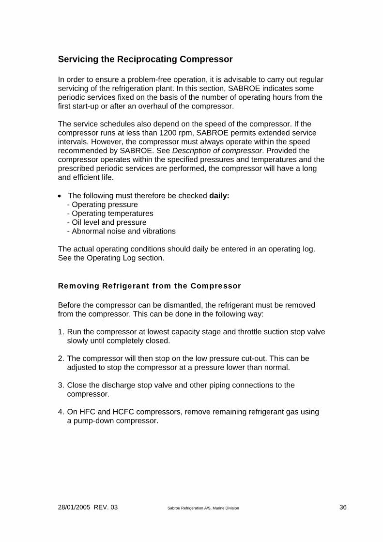
Servicing the Reciprocating Compressor In order to ensure a problem-free operation, it is advisable to carry out regular servicing of the refrigeration plant. In this section, SABROE indicates some periodic services fixed on the basis of the number of operating hours from the first start-up or after an overhaul of the compressor. The service schedules also depend on the speed of the compressor. If the compressor runs at less than 1200 rpm, SABROE permits extended service intervals. However, the compressor must always operate within the speed recommended by SABROE. See Description of compressor. Provided the compressor operates within the specified pressures and temperatures and the prescribed periodic services are performed, the compressor will have a long and efficient life. • The following must therefore be checked daily: - Operating pressure - Operating temperatures - Oil level and pressure - Abnormal noise and vibrations The actual operating conditions should daily be entered in an operating log. See the Operating Log section. Removing Refrigerant from the Compressor Before the compressor can be dismantled, the refrigerant must be removed from the compressor. This can be done in the following way: 1. Run the compressor at lowest capacity stage and throttle suction stop valve
slowly until completely closed. 2. The compressor will then stop on the low pressure cut-out. This can be
adjusted to stop the compressor at a pressure lower than normal. 3. Close the discharge stop valve and other piping connections to the
compressor. 4. On HFC and HCFC compressors, remove remaining refrigerant gas using
a pump-down compressor.
28/01/2005 REV. 03 Sabroe Refrigeration A/S, Marine Division 37
Scheduled Services Note: The following instructions apply to the compressor only. Servicing of the refrigeration plant is described in a separate section. Service the compressor motor according to your own instructions. For the various scheduled services, SABROE can supply ready-made spare parts sets, which it would be an advantage to have before carrying out the scheduled service. In the event that the compressor cannot operate, start evacuation as described under pt. 3, and remember also to close the suction stop valve.

28/01/2005 REV. 03 Sabroe Refrigeration A/S, Marine Division 38
Scheduled services
No. Operating hours < 1200 rpm
Operating hours > 1200 rpm
Activity
1 75 50 1.1 Clean suction filter 1.2 Check tension of driving belts
2
300
200
2.1 Check or change oil. When changing oil, clean oil filter as well. See the following section: Assessing the oil. 2.2 Clean suction filter. 2.3 Check that the following functions correctly: Safety automatics Heating rod V-belt drive. 2.4 Retighten external piping connections. 2.5 Check oil return system from oil separator
3
7500
5000
3.1 Check or change oil. When changing oil, clean oil filter as well. See the following section: Assessing the oil. 3.2 Clean suction filter. 3.3 Check that the following functions correctly: Safety automatics Heating rod V-belt drive Oil return system from oil separator
4
15000
10000
4.1 Check or change oil. When changing oil, clean oil filter, too. See section: Assessing the oil. 4.2 Clean suction filter 4.3 Check the following: Oil cooling system Water cooling system for any deposits and clogging Safety automatics Heating rod V-belt drive Oil return system from oil separator Valves Cylinders Pistons, gudgeon pins and gudgeon pin bearings Piston and oil scraper rings Unloading valve Seal for leak 4.4 Change: V-belts
5 22500 15000 5.1 Check V-belt drive

28/01/2005 REV. 03 Sabroe Refrigeration A/S, Marine Division 39
Scheduled services
No. Operating hours < 1200 rpm
Operating hours > 1200 rpm
Activity
6
30000
20000
6.1 Change compressor oil, Change oil filter cartridge Clean crankcase 6.2 Clean suction filter 6.3 Check the following: Oil cooling system Water cooling system for any deposits and clogging Safety automatics Heating rod V-belt drive Valves Cylinders Pistons, gudgeon pins and gudgeon pin bearings Piston and oil scraper rings Unloading mechanism Seal for leak Oil pump and drive Check valves 6.4 Change: V-belts Half-sections of bearing for connecting rod
7 37500 25000 Same as service No. 5 8 45000 30000 Same as service No. 4 9 52500 35000 Same as service No. 3 10 60000 40000 Major overhaul; contact SABROE Refrigeration Then repeat scheduled services from No. 3 and onward.

28/01/2005 REV. 03 Sabroe Refrigeration A/S, Marine Division 40
Lubricating Oil Lubricating Oil Requirements Above all, the refrigerating machine oil must provide satisfactory lubrication of the compressor, even at the relatively high temperatures occurring during compression. It must be incapable of cooking at such high temperatures and must not precipitate solid constituents such as paraffin or wax at the lowest occurring temperatures. The oil must not have any corrosive effect, whether alone or mixed with refrigerant. Sabroe Marine delivers standard Sabroe oil General Rules for Use of Lubricating Oil in Refrigeration Compressors • Only fresh, clean refrigerating machine oil may be charged. • Use grade of oil originally prescribed for compressor. • As far as possible, avoid mixing different types of oil. Mixed oil is generally
inferior to the two original oils. Mixing various types of oil may give rise to formation of sludge, which will lodge in valves and filters.
• Should it be necessary to switch to another brand of oil, this must be done at the same time as a complete change of oil in the compressor and draining off all oil from the refrigeration plant is carried out. In the guarantee period, please do not change to another oil.
• The refrigerating machine oil must be free of moisture, which may other-wise give rise to operating malfunctions and attacks of corrosion.
The oil should therefore be purchased in containers corresponding to the quantity to be used for one single topping-up. The oil containers must be kept carefully sealed. Note: It is inadvisable to re-use oil, which has been drained from a compressor or plant. This oil will have absorbed moisture from the air and may cause operating problems. Always switch off the power to the heating rod before draining off the oil. If, after reading the above, any doubt exists as to the type of oil which has been used in your compressor, you are recommended to contact SABROE, rather than risk charging the compressor with unsuited oil.

28/01/2005 REV. 03 Sabroe Refrigeration A/S, Marine Division 41
Charging Refrigeration Compressor with Lubricating Oil The reciprocating compressors are delivered from Sabroe with 1. charge of oil. Usually, it is not necessary to top-up with lubrication oil. It is, however, possible to pour oil into the compressor through the plug above the sight glass.
28/01/2005 REV. 03 Sabroe Refrigeration A/S, Marine Division 42
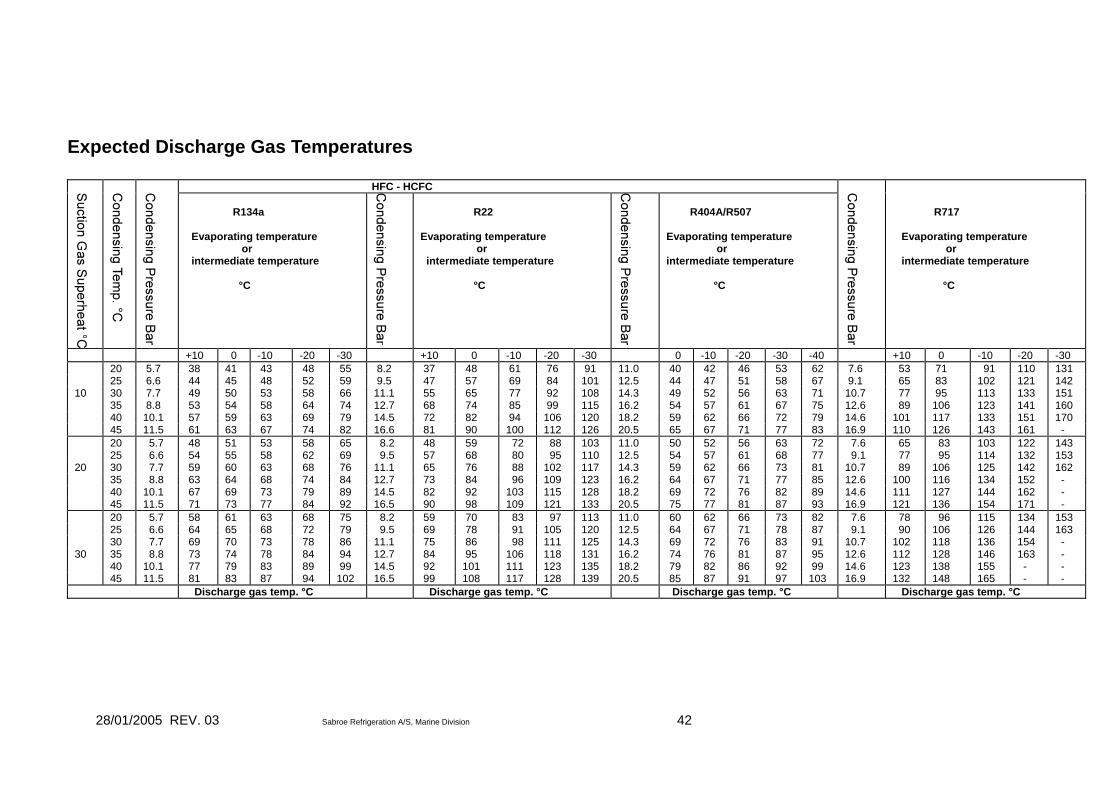
Expected Discharge Gas Temperatures
HFC - HCFC
R134a Evaporating temperature or intermediate temperature °C
R22 Evaporating temperature or intermediate temperature °C
R404A/R507 Evaporating temperature or intermediate temperature °C
R717 Evaporating temperature or intermediate temperature °C
+10 0 -10 -20 -30 +10 0 -10 -20 -30 0 -10 -20 -30 -40 +10 0 -10 -20 -30 20 5.7 38 41 43 48 55 8.2 37 48 61 76 91 11.0 40 42 46 53 62 7.6 53 71 91 110 131 25 6.6 44 45 48 52 59 9.5 47 57 69 84 101 12.5 44 47 51 58 67 9.1 65 83 102 121 142 10 30 7.7 49 50 53 58 66 11.1 55 65 77 92 108 14.3 49 52 56 63 71 10.7 77 95 113 133 151 35 8.8 53 54 58 64 74 12.7 68 74 85 99 115 16.2 54 57 61 67 75 12.6 89 106 123 141 160 40 10.1 57 59 63 69 79 14.5 72 82 94 106 120 18.2 59 62 66 72 79 14.6 101 117 133 151 170 45 11.5 61 63 67 74 82 16.6 81 90 100 112 126 20.5 65 67 71 77 83 16.9 110 126 143 161 - 20 5.7 48 51 53 58 65 8.2 48 59 72 88 103 11.0 50 52 56 63 72 7.6 65 83 103 122 143 25 6.6 54 55 58 62 69 9.5 57 68 80 95 110 12.5 54 57 61 68 77 9.1 77 95 114 132 153 20 30 7.7 59 60 63 68 76 11.1 65 76 88 102 117 14.3 59 62 66 73 81 10.7 89 106 125 142 162 35 8.8 63 64 68 74 84 12.7 73 84 96 109 123 16.2 64 67 71 77 85 12.6 100 116 134 152 - 40 10.1 67 69 73 79 89 14.5 82 92 103 115 128 18.2 69 72 76 82 89 14.6 111 127 144 162 - 45 11.5 71 73 77 84 92 16.5 90 98 109 121 133 20.5 75 77 81 87 93 16.9 121 136 154 171 - 20 5.7 58 61 63 68 75 8.2 59 70 83 97 113 11.0 60 62 66 73 82 7.6 78 96 115 134 153 25 6.6 64 65 68 72 79 9.5 69 78 91 105 120 12.5 64 67 71 78 87 9.1 90 106 126 144 163 30 7.7 69 70 73 78 86 11.1 75 86 98 111 125 14.3 69 72 76 83 91 10.7 102 118 136 154 - 30 35 8.8 73 74 78 84 94 12.7 84 95 106 118 131 16.2 74 76 81 87 95 12.6 112 128 146 163 - 40 10.1 77 79 83 89 99 14.5 92 101 111 123 135 18.2 79 82 86 92 99 14.6 123 138 155 - - 45 11.5 81 83 87 94 102 16.5 99 108 117 128 139 20.5 85 87 91 97 103 16.9 132 148 165 - - Discharge gas temp. °C Discharge gas temp. °C Discharge gas temp. °C Discharge gas temp. °C
28/01/2005 REV. 03 Sabroe Refrigeration A/S, Marine Division 43
Maintenance of SBO Reciprocating Compressors Generally When the compressor requires maintenance, it is important to follow the instructions given below. In order to make sure that the compressor is working correctly, the gauge measurements and screw torques must be strictly adhered to. Before opening the compressor, it is expedient to ensure that you have spares of those seals and gaskets to be stripped down or dismantled. An O-ring, which has been exposed to oil and heat for any length of time, may have expanded so much that it cannot be refitted. All seals and gaskets used are resistant to oil, HFC/HCFC. All O-rings are made of neoprene rubber. In the following sections and paragraphs reference is made to position numbers on the assembly drawings at the end of this manual. However, for SBO21 and SBO22 the position numbers may deviate from those of SBO41, SBO42 and SBO43. In such cases reference is made to the drawings for SBO41, SBO42 and SBO43. Pump-Down Before opening up the compressor for inspection, the pressure inside must be lowered to slightly above atmospheric pressure. This can be done in the following way, depending on whether the compressor is operational or defective: The Compressor is Operational Run the compressor at minimum capacity at normal operating temperature. Adjust the low-pressure control so that the compressor stops at a suction pressure of approx. 0.1 bar. Throttle the suction stop valve very slowly. Keep an eye on the suction pressure gauge. The suction pressure must be lowered slowly enough to give the refrigerant dissolved in the oil time to escape without the oil foaming. This is of great importance in compressors running on HFC/HCFC. Once the pressure is down to approx. 0.1 bar, stop the compressor and perform the following steps in the order specified:

28/01/2005 REV. 03 Sabroe Refrigeration A/S, Marine Division 44
• Close suction stop valve.
• Cut off power to compressor motor.
• Close discharge stop valve.
• Drain off last remains of refrigerant gas.
• Having ensured that power to compressor motor cannot be inadvertently connected,
the compressor is ready for opening. For this purpose, remove all fuses to the electric motor. The Compressor is Inoperative • Leave heating rod in crankcase connected for a couple of hours before the
compressor is due to be opened in order to heat up oil. Warm oil does not contain much refrigerant.
• Suction stop valve must be open while heating rod is connected.
• Keep discharge stop valve closed.
• Close suction stop valve and disconnect heating rod.
• Equalize the pressure in the compressor.
• Once pressure has been equalized to atmospheric pressure, the compressor is ready for opening. Remember to make sure that power cannot be connected inadvertently and start the motor.
Consequently, remove all fuses to the electric motor. Dismantling and Assembly The following sections describe the individual components. When dismantling and assembling, parts should generally be fitted in the same position from which they were taken and should therefore be marked as they are removed. Further they should be thoroughly cleaned, checked and lubricated prior to being reassembled. Valve Intermediate Plate incl. Suction and Discharge Valves The valves are plate valves, consisting of an intermediate plate, pos. 100 upon which suction and discharge valve plates are mounted. The intermediate plate is positioned right under the top cover. When the top cover has been removed this intermediate plate becomes visible and can be removed, too.

28/01/2005 REV. 03 Sabroe Refrigeration A/S, Marine Division 45
The intermediate plate is delivered with suction and discharge valve plates as one spare part, including complete gaskets. Mounting • Without causing any damage clean all gasket surfaces thoroughly of any gasket
remains.
• Lubricate the new gaskets pos. 101 and pos. 102 in refrigerating machine oil and check that the gaskets are facing correctly in relation to the holes for the fixing screws.
• Check that the intermediate plate is positioned correctly before fitting top cover. • Insert screws pos. 104 and tighten cross-wise with a torque moment as indicated in
instruction on Torque moments for screws and bolts.
• After approx. 25 hours of operation screws and top cover should be retightened.
28/01/2005 REV. 03 Sabroe Refrigeration A/S, Marine Division 46
Shaft Seal Fig 1 Generally This series of open reciprocating compressors is fitted with a high quality shaft seal. This consists of a rotating and a stationary unit (see fig. 1). This maintenance instruction describes the exchange of the shaft seal in case of damage. Important Notice! Work on the compressor or the refrigeration circuit may only be carried out by qualified personnel.

28/01/2005 REV. 03 Sabroe Refrigeration A/S, Marine Division 47
Inspection A routine inspection of the shaft seal is not normally necessary. With regard to increased operational reliability it is, however, recommended to make an inspection in connection with an oil change, faults in the oil supply and also at regular intervals when operating with high discharge gas temperatures and oil temperatures. Special attention should be given to cracks in the O-ring, as well as wear, scoring and material deposits, oil carbon and copper plating on the sealing ring. An oil leak rate of 0.05 cm3/h is within the tolerance. Note: During the running in period of the new shaft seal (about 250 hours) an increased oil leak rate may occur.
Possible Causes of Failure • lack of lubrication (insufficient oil supply, high refrigerant concentration in the oil) • heavy wear of driving parts (high proportion of dirt in the oil) • axial play of crankshaft too large • overheating (hardening and cracking of O-rings, oil carbon) • strong vibration (insufficient fixing of coupling or drive pulley, drive not smooth
enough, coupling or drive pulley displaced) • belt tension too high Removal Preparation & Recommendations Tools and Other Materials • Hexagon spanner and key for internal hexagon • Plastic hammer • Hooks (to pull out rotating unit) • Scraper, smoothing cloth (to remove gasket remains) • Polishing cloth (to smooth the surface of the shaft) The pressure in the compressor must first be released. According to the drive system, the drive pulley, motor, coupling housing, coupling and key should then be removed. Attention! Working on a compressor, which is under pressure, can lead to serious injury. Removing the Shaft Seal • Loosen the fixings of the shaft seal cover ((2) in Fig 1) evenly (pay attention to the
spring tension of the shaft seal). • Release the cover with light hammer taps if necessary and take off the stationary unit
(1). Remove gasket remains. • Carefully slide the rotating unit (3) from the shaft, which is secured against turning by
a drive pin (4). If required the hooks can be located in the slot (5) to assist.

28/01/2005 REV. 03 Sabroe Refrigeration A/S, Marine Division 48
Attention! This procedure must be carried out very carefully in order to avoid damaging the surface of the shaft. Fitting Preparation & Recommendations When strong wear to the drive parts is suspected (contaminated oil, strong deposits) a precautionary compressor exchange or overhaul is urgently recommended. The shaft, flange (gasket remains) and the shaft seal chamber should be cleaned very thoroughly. Any deposits on the shaft must be carefully removed. If necessary the surface can be smoothed with fine polishing cloth soaked in oil (not smoothing cloth). Special Recommendations • Always exchange the complete shaft seal when possible • Never re-use old O-rings • Do not touch the sealing surfaces Fitting the Shaft Seal • Oil the rotating sealing surface, O-ring and shaft with clean refrigeration oil. Do not
oil the asbestos-free gasket or the flange surface. • Slide the rotating unit (3) onto the shaft with a turning motion up to the shoulder in
the shaft. The drive pin (4) must be located in the slot provided. • Lightly oil the sealing surface of the stationary unit (1), then mount the whole unit
including the gasket over the shaft. The gap between the crankcase flange and the cover should be approx 5 mm (spring tension).
• The fixing screws should be evenly tightened in a crosswise order with a torque wrench (torque 40 Nm).
28/01/2005 REV. 03 Sabroe Refrigeration A/S, Marine Division 49
Cleaning of Oil Filter The oil filter should be cleaned at regular intervals. See section on Servicing the compressor. Please note in this connection that often the filter must be cleaned already after a short operating period following the initial start-up. This is a consequence of the tiny dirt particles that will be coming from the plant during its first operating period. Clean the oil filter in a suitable dissolvent and blow clean with pressurized air before refitting.
Suction Filter Between suction stop valve pos. 60 and compressor a fine-meshed filter has been fitted pos. 57. The purpose of this filter is to prevent that impurities from the plant are conveyed with the gas flow into the compressor. Clean the suction filter at regular intervals as stated in the section on Servicing the reciprocating compressor. On cleaning the filter dismantle suction stop valve pos. 34 by removing screws pos. 59. The filter pos. 57 and gaskets pos. 58 can now be removed without the use of any tools. Clean the filter in a suitable dissolvent and blow clean with pressurized air.

28/01/2005 REV. 03 Sabroe Refrigeration A/S, Marine Division 50
Stop Valves Suction and discharge stop valves are used to cut off the compressor from the plant. They are closed tightly by manual tightening. Hence, it is not advisable to use any tools in order to close the valve as this would just lead to overloading of the valve parts. The valve spindle is fitted with a maintenance-free gasket which needs no replacement. Further, the valve is fitted with a backsealing, which is brought into operation when the valve is completely open and the valve cone screwed back towards the cylinder head (anticlockwise rotation). Note: In case the compressor is operating, the valve cone should not be screwed completely back against the cylinder head as any safety pressure controls connected to the valve housing will hereby be blocked.
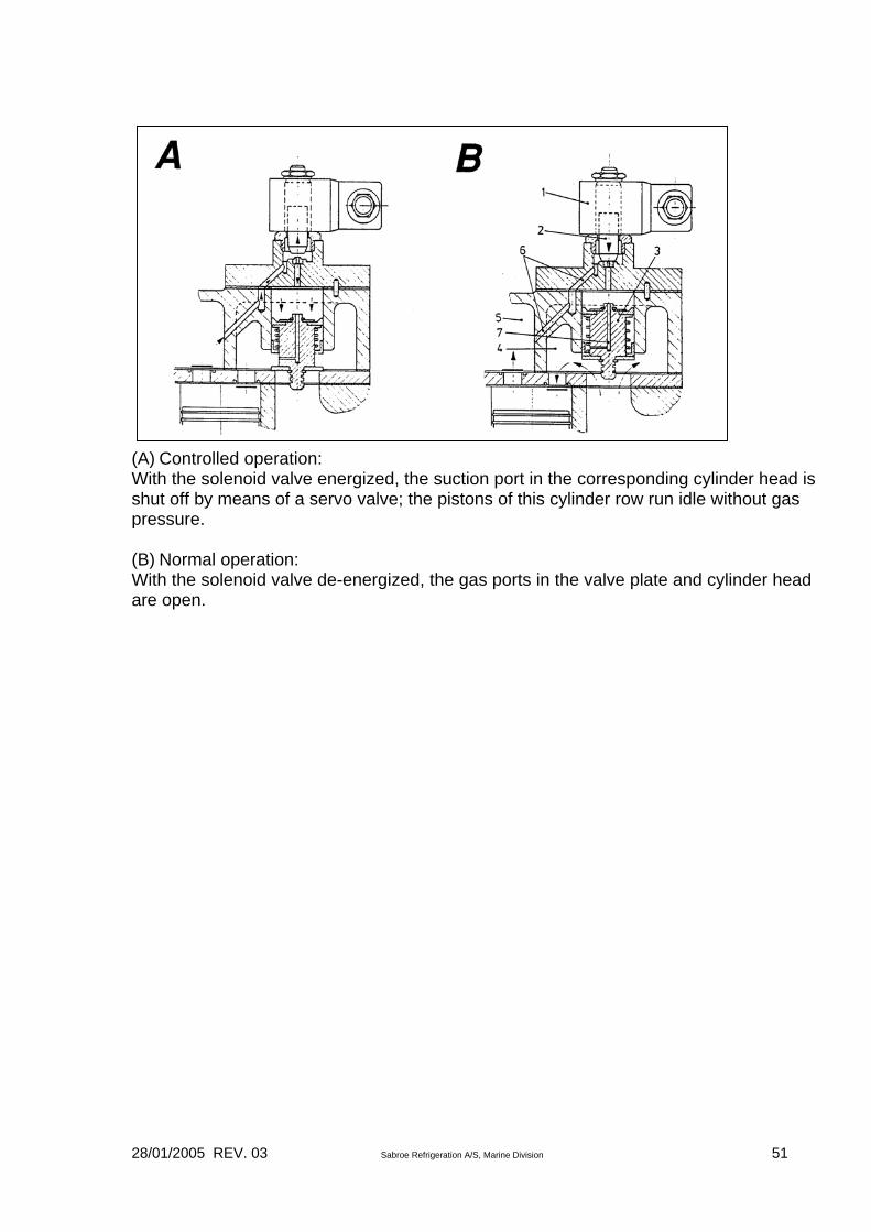
Capacity Regulation for Compressor SBO41, SBO42 and SBO43 The SBO four-cylinder compressors can be delivered with a system for stage-wise capacity regulation, from 100% to 50%. Function Capacity regulation is obtained when the solenoid valve, fitted in the top cover, closes the access to the two cylinders, positioned under the same top cover. This makes the inlet pressure to the cylinder drop to zero bar. At the same time the compressor capacity is reduced to 50%. However, a little gas will be flowing through the closed solenoid valve, hereby ensuring the necessary cooling and lubrication of the cylinders. This capacity regulation permits a certain reduction in power consumption. Note: Stop the compressor and check that the solenoid valve works correctly. At a current impulse to the solenoid valve the characteristic valve stroke must be heard!
28/01/2005 REV. 03 Sabroe Refrigeration A/S, Marine Division 51
(A) Controlled operation: With the solenoid valve energized, the suction port in the corresponding cylinder head is shut off by means of a servo valve; the pistons of this cylinder row run idle without gas pressure. (B) Normal operation: With the solenoid valve de-energized, the gas ports in the valve plate and cylinder head are open.
28/01/2005 REV. 03 Sabroe Refrigeration A/S, Marine Division 52
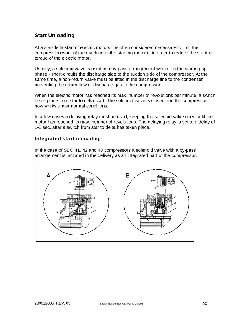
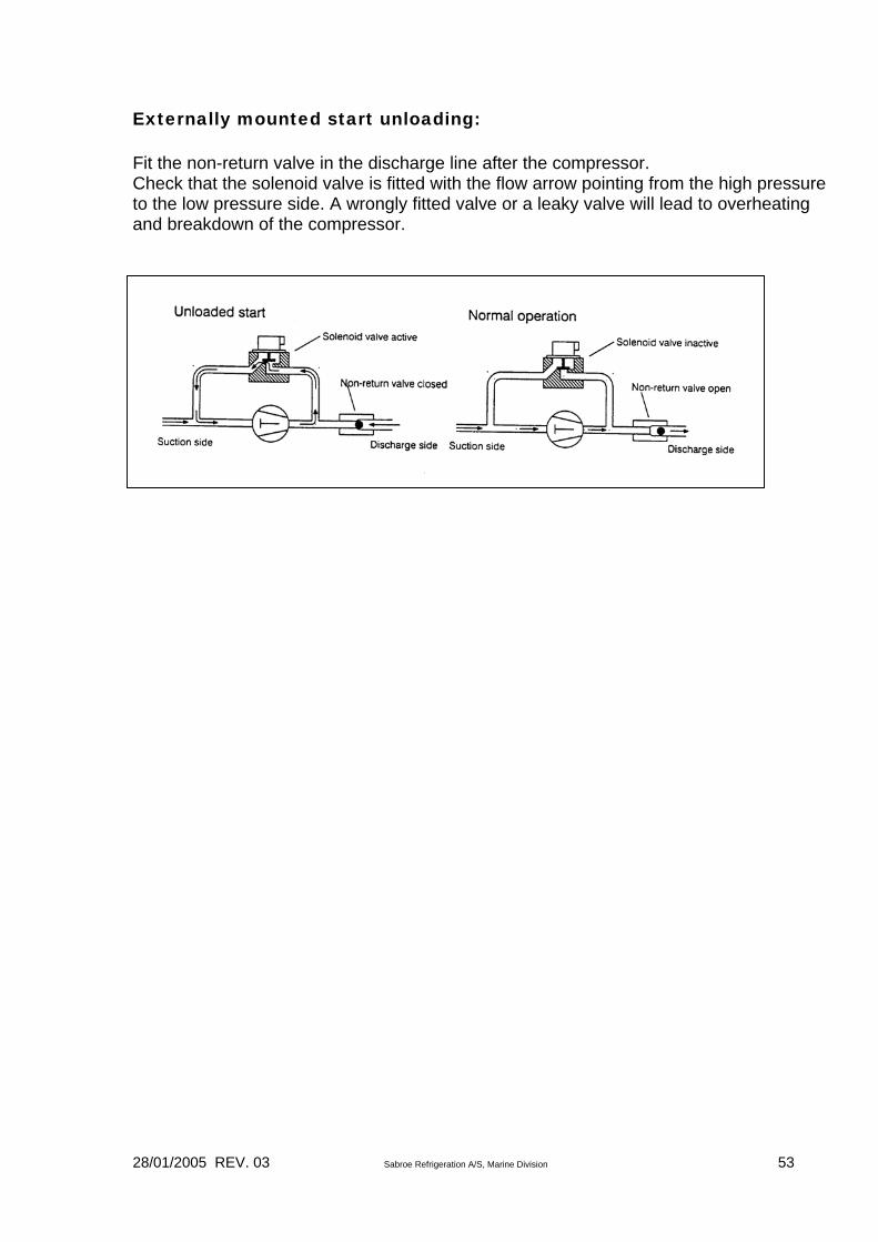
Start Unloading At a star-delta start of electric motors it is often considered necessary to limit the compression work of the machine at the starting moment in order to reduce the starting torque of the electric motor. Usually, a solenoid valve is used in a by-pass arrangement which - in the starting-up phase - short-circuits the discharge side to the suction side of the compressor. At the same time, a non-return valve must be fitted in the discharge line to the condenser preventing the return flow of discharge gas to the compressor. When the electric motor has reached its max. number of revolutions per minute, a switch takes place from star to delta start. The solenoid valve is closed and the compressor now works under normal conditions. In a few cases a delaying relay must be used, keeping the solenoid valve open until the motor has reached its max. number of revolutions. The delaying relay is set at a delay of 1-2 sec. after a switch from star to delta has taken place. Integrated start unloading: In the case of SBO 41, 42 and 43 compressors a solenoid valve with a by-pass arrangement is included in the delivery as an integrated part of the compressor.
28/01/2005 REV. 03 Sabroe Refrigeration A/S, Marine Division 53
Externally mounted start unloading: Fit the non-return valve in the discharge line after the compressor. Check that the solenoid valve is fitted with the flow arrow pointing from the high pressure to the low pressure side. A wrongly fitted valve or a leaky valve will lead to overheating and breakdown of the compressor.

28/01/2005 REV. 03 Sabroe Refrigeration A/S, Marine Division 54
Heating Rods for Oil Heating The SBO compressors are delivered in a standard execution with built-in heating rod in the crankcase. The purpose of the heating rod is to keep the oil in the crankcase warm even during standstill of the compressor. This ensures a low content of refrigerant in the oil. Too much refrigerant in the oil makes it loose its lubricating properties. This may lead to damage of the movable parts in the compressor. Further, the danger exists that the oil, during start-up of the compressor, foams so vigorously that the lubricating pressure will disappear. Before start-up the heating rod should be switched on for at least 8 hours. Note: The heating rod must not be switched on if the oil level in the vessel is below minimum in the sight glass. While the compressor is operating, it is usually switched off. Further, remember to switch off the heating rod if the compressor crankcase is opened for inspection.
Compressor type Effect Watt
Voltage Volt
SBO 21, 22, 41, 42, 43 70 230 SBO 21, 22, 41, 42, 43 70 110

28/01/2005 REV. 03 Sabroe Refrigeration A/S, Marine Division 55
Torque Moments for Screws and Bolts On mounting, screws and bolts must be tightened with the moments indicated below: Cylinder head/valve plate: tighten screws crosswise and at least in two steps (50% and 100%) Normal screw fixings A B C SBO 21, 22, 41, 42, 43
Moment Nm
Moment Nm
Moment Nm
M6 51 51 51 M8 34 34 34 M10 34 34 34 M12 51 51 51 M16 34 51 51 A Without flat gasket B With gasket free of asbestos and screw quality 10.9 C With gasket containing asbestos and screw quality 8.8 SBO 21, 22, 41, 42, 43
Moment Nm
Oil pump M8 23 Shut off valves with oval flange M6/M8/M10 9.7 / 25 / 54 Sight glass fixing M6*/M6**/M8 8 / 11 / 14 Plugs NPTF 1/8" 10 - 13 Plugs NPTF 1/4" 20 - 23 Plugs NPTF 3/8" 42 - 47 Plugs NPTF 1/2" 64 - 69 Plugs NPTF 3/4" 98 - 108 Oil drain plug M22 Al 90 Oil drain plug M22 Cu 135 - 155 Oil drain plug M26 Al 110 Oil drain plug M26 Cu 155 - 175 Connecting rod screws M6 (10.9) 16 Connecting rod screws M8 (8.8) 25.5 * Quality 8.8 - flat gasket ** Quality 10.9 - for O-ring-version
28/01/2005 REV. 03 Sabroe Refrigeration A/S, Marine Division 56
Refrigeration Plant Maintenance Operational Reliability The main causes of operating malfunctions of the plant are: 1. Incorrect control of liquid supply to the evaporator 2. Moisture in the plant 3. Air in the plant 4. Anti-freezing liquid is missing 5. Congestion due to metal shavings and dirt 6. Congestion due to iron oxides 7. Congestion due to copper oxides 8. Inadequate refrigerant charge Below, some information is given about ways of keeping contaminants out of the refrigerating system and at the same time facilitating day-to-day supervision of the refrigeration plant. Pumping Down the Refrigeration Plant Before dismantling any parts of the refrigeration plant for inspection or repair, pump-down must be carried out. 1. Open suction and discharge stop valves on compressor.
2. Close liquid stop valve after condenser or receiver so that liquid refrigerant can be
collected in the tank. Any solenoid valves in the liquid line should be opened by force, adjusting the thermostat to its lowest position so that the liquid line can be bled of refrigerant. Adjust any constant-pressure valves to bring evaporator pressure down to atmospheric pressure.
3. Start up the compressor. Adjust regulating system to lower suction pressure.
4. Keep a close eye on the suction pressure gauge! When the suction pressure is equal to atmospheric pressure, stop the compressor and quickly shut off the discharge stop valve. Shut off any stop valve in the oil return line. If the receiver has an extra stop valve in the feed line, this can be closed; practically the entire refrigerant charge will then remain shut off in the receiver. Note: The receiver must not be overfilled! There should be a minimum gas volume of 5%.
5. A slight overpressure should normally remain in the piping system - this safeguards the system from penetration of air and moisture.
6. Before dismantling parts, the operator should put on a gas mask.
28/01/2005 REV. 03 Sabroe Refrigeration A/S, Marine Division 57
Dismantling Plant In order to prevent moisture penetrating into the refrigeration plant during any repair work, it is advisable to follow the rules below: 1. No component should be opened unnecessarily.
2. When dismantling the system, the pressure in the system should be a little higher
than atmospheric pressure.
3. Note: If the piping system is colder than the surroundings, there is a considerable risk of damp precipitation (condensation) on cold plant parts. Plant components to be dismantled must be warmer than the ambient temperature.
4. Only one point should be opened at a time.
5. Plug, close or at least cover opening with oiled paper or suchlike.
6. Be aware of the possibility of filters being very moist.
Leak Testing and Pump-Down of Refrigeration Plant Before charging refrigerant into that part of the refrigeration plant which has been opened, this should be pressure-tested as described in the section entitled Pressure testing. Afterwards, pump down in order to eliminate air and moisture. In this regard, consult the section on Evacuation. Otherwise, follow the instructions given in the separate instruction manual on plant components. Note: If the oil in the crankcase of the piston compressor has been in contact with the atmospheric air for any length of time, it must be replaced with fresh oil of the same grade and make.

28/01/2005 REV. 03 Sabroe Refrigeration A/S, Marine Division 58
Trouble-Shooting on the Reciprocating Compressor Plant Operating Conditions Experience shows that pressure and temperature variations in a refrigeration circuit can provide information about the operating condition of the refrigeration plant. In particular, suction and condenser pressures as well as the temperatures of suction and discharge gases may provide important information as to the operating conditions of the plant. It often takes only very slight modifications of variable pressures and temperatures to produce considerable changes in operating conditions. Using the following trouble-shooting chart, it is possible to ascertain the cause of and remedy for any operating disturbance. Using the trouble-shooting chart In the following chart, each individual error option is indicated by a code number in the left-hand column, the error being briefly described in the next column. The third column states code numbers for the possible causes of the error. The code numbers refer to the subsequent chart. The section entitled Remedying malfunctions states how to remedy the observed error. See the following example for the correct procedure. Example Observed error: discharge pipe temperature too low - error code 15. Cause codes: 26 (liquid in suction line) 32 (too much coolant/air to condenser) 39 (expansion valve produces too little superheating) Any explanatory comments will be stated in the section that follows.

28/01/2005 REV. 03 Sabroe Refrigeration A/S, Marine Division 59
Error Code
Observed Error
Cause Code
1 2 3 4 5 6 7 8
Compressor fails to start Compressor starts and stops too often Compressor starts but stops again immediately Compressor operates continuously Abnormal noise from compressor Insufficient capacity on compressor Slugging in compressor during start up Slugging in compressor during operation
1, 2, 3, 4, 5, 6, 7, 9, 10, 12, 14. 9, 10, 11, 13, 21, 22, 23, 24, 32, 34, 35, 36, 37, 40, 41, 43, 44, 51, 52, 54, 56, 59. 3, 5, 6, 9, 10, 11, 12, 13, 14, 15, 17, 18, 41, 42, 49, 50, 55, 61. 8, 21, 22, 24, 41, 46, 52, 53, 56, 60. 16, 17, 18, 19, 26, 48, 49, 50, 51, 52, 53, 54, 56, 57, 58. 13, 15, 17, 18, 20, 21, 22, 23, 24, 32, 34, 35, 36, 37, 40, 41, 44, 45, 46, 49, 50, 51, 52, 53, 56, 60. 16, 18, 26, 37, 38, 39, 44, 56, 61. 21, 23, 26, 37, 39.
9 10 11 12 13
Excessive condenser pressure Too low condenser pressure Excessive suction pressure Too low suction pressure Too low oil pressure
9, 25, 28, 29, 30, 31, 33. 22, 32, 51, 52, 54, 60. 13, 17, 26, 34, 39, 52, 53, 54, 5, 60. 11, 13, 20, 21, 22, 23, 32, 35, 36, 37, 40, 41, 42, 44, 45, 56, 59. 12, 15, 17, 18, 26, 49, 50, 55.
14 15 16
Excessive discharge pipe temperature Too low discharge pipe temperature Excessive oil temperature
11, 21, 22, 23, 28, 29, 30, 31, 33, 34, 35, 36, 37, 40, 41, 46, 52, 54. 26, 32, 39. 33, 34, 35, 36, 37, 40, 50, 52.
17 18 19
Oil level in crankcase falling Oil foaming vigorously in crankcase Crankcase "sweating" or frosting up
16, 18, 20, 26, 51, 57, 58. 16, 26, 39, 61. 16, 18, 26, 37, 39.
20 21
Capacity regulating oscillatingImpossible to bleed plant
13, 15, 16, 17, 18, 49, 55, 56. 10, 43, 51, 52, 53, 54, 60.

28/01/2005 REV. 03 Sabroe Refrigeration A/S, Marine Division 60
Code
Case
Code
Case
1 2 3 4 5 6 7 8 9 10 11 12 13 14 15 16 17 18 19 20 21 22 23 24 25 26 27
No power - master switch does not cut in Blown fuses - loose wiring or connections Electrical voltage too low No control current Motor protection device activated Control current circuit openPump/fan not started Welded contacts in motor protection High-pressure cut-out has cut Low-pressure cut-out has cut Low-pressure cut-out differential too small Oil pressure cut-out has cut Capacity regulator incorrectly set Defrosting timer breaks current Oil charge insufficient Compressor capacity too high during start-up Oil pressure too low (adjust oil pressure regulating valve) Oil foaming in crankcase Oil overcharge Poor oil return - oil in evaporators Restricted supply of refrigerant Refrigerant charge insufficient Refrigerant vapour in liquid line Leaky refrigeration plant Refrigerant overcharge Liquid in suction line At low temperature operation, degree of charge in evaporators rises
31 32 33 34 35 36 37 38 39 40 41 42 43 44 45 46 47 48 49 50 51 52 53 54 55 56 57
Condenser needs cleaning Too much coolant/air to condenser Water valve closed External pressure equalization on expansion valve closed Expansion valve partly clogged by ice, dirt, wax. Expansion valve has lost charge Expansion valve sensor misplaced Expansion valve is leaky Expansion valve provides too little superheating Expansion valve produces excessive superheating Filters in liquid/suction lines clogged Solenoid valve in liquid/suction lines closed Solenoid valve leaky Evaporator iced up or clogged Cooling air being recirculated (short-circuited) Excessive load on plant Refrigerant collecting in cold condenser (close off by-pass) Coupling misaligned or loose bolts Oil pump defective Bearings worn out or defective Defective piston rings or worn cylinder Discharge valves defective or leaky Suction valves defective or leaky Compressor by-pass open - leaky safety valve Compressor oil filter clogged Capacity regulator defective Solenoid valve in oil return

28/01/2005 REV. 03 Sabroe Refrigeration A/S, Marine Division 61
28 29 30
Insufficient coolant/air to condenser Temperature of coolant/air too high Non-condensable gases in condenser
58 59 60 61
clogged/ defective Filter in oil return clogged Compressor capacity too high Compressor capacity too low Heating element in crankcase defective
Remedying Malfunctions 1. Compressor fails to start: 1.6
Control current circuit open owing to activated: Pressure cut-outs Thermostats Motor protection device Defrosting timer
Pinpoint open switch and remedy cause of interruption.
1.9 High-pressure cut-out has cut
Reset pressure cut-out and investigate cause of high condenser pressure.
1.10 Low-pressure cut-out has cut
Compressor cannot start before suction pressure has risen above setpoint for pressure cut-out restarting.
1.12 Oil-pressure cut-out has cut Compressor starts at reset. Check oil level. If oil foams in crankcase, see section 18.
2. Compressor starts and stops too often: 2.9
High-pressure cut-out cuts at high pressure
High condenser pressure - see section 9. Check condenser cooling and adjust pressure cut-out to correct breaking pressure - see table Pressure and temperature settings. Replace defective pressure cut-out.

28/01/2005 REV. 03 Sabroe Refrigeration A/S, Marine Division 62
2.10 Low-pressure cut-out cuts at
too low suction pressure Low suction pressure - see section 12. If low-pressure cut-out is set too high, adjust pressure cut-out.
2.11 Low-pressure cut-out differential is too small between stopping and starting
Increase differential pressure - see also special instructions.
2.13 Compressor capacity too high
Check operating conditions and, if necessary, reduce capacity.
2.41
Filter in suction line clogged
Check suction filters on compressor.
2.43 Solenoid valve in liquid line does not close tight
Check direction of flow. Replace defective valve.
2.52 Discharge valves on compressor are leaky
At compressor stop, pressure equalizes relatively quickly between suction and discharge side. Clean or change discharge valves.
3. Compressor starts, but stops again immediately: 3.5
Motor protection cuts
Look for cause of overloading. If star-delta start, set starting time at minimum.
3.10 Low-pressure cut-out has cut
Open any suction stop valve which is closed.
3.12 Defective oil-pressure cut-out
Replace cut-out - see special instructions.
3.15 Oil charge insufficient Top up with oil and investigate cause of oil shortage.
3.18 Oil pressure failing owing to formation of foam in oil.
Reduce capacity. See sections 17 and 18.

28/01/2005 REV. 03 Sabroe Refrigeration A/S, Marine Division 63
4. Compressor operates continuously: 4.10
Thermostat or low-pressure cut-out does not cut at too low temperature/pressure
Adjust operating points.
4.21 Restricted supply of refrigerant to evaporator. Compressor working at too low suction pressure.
Remove dirt in filters and check function of expansion device as per special instructions.
4.22 Refrigerant charge insufficient.
Top up with refrigerant of correct type.
5. Abnormal noise from compressor: 5.16
Compressor capacity too high during start-up
Reduce capacity.
5.17 Oil pressure too low See section 13. 5.26 Liquid refrigerant in suction
line Slugging. See points 7 and 8. Adjust expansion or float valves.
5.48 Incorrect alignment of motor and compressor. Loose bolts in coupling
Check alignment as per special instructions. Tighten with torque wrench.
5.50 Worn or defective bearings Overhaul or replace 5.51 5.53 5.57 5.58
Too much oil circulating through the plant, resulting in too low oil level in compressor
Check oil level. Solenoid valve, filter or jets in oil return system may be clogged. Leaky suction valve ring plates, piston rings and worn-out cylinder may also produce such oil consumption.
5.56 Capacity regulation oscillating owing to failing oil pressure
Low oil pressure - see section 13.

28/01/2005 REV. 03 Sabroe Refrigeration A/S, Marine Division 64
6. Too little capacity on compressor: 6.15
Insufficient oil charge
Top up with fresh oil of same type and make.
6.44 Iced-up evaporator Defrost evaporator; adjust defrosting time if required.
6.49 Defective oil pump and hence failing oil pressure
Repair or replace oil pump.
6.56 Defective capacity regulating system
Cause is most often failure in oil pressure or refrigerant in oil; see section 4.5.
7. Slugging in compressor during start-up:
Slugging in the compressor should not occur, because at worst this can cause rupture of the valve ring plates and damage to the built-in relief devices. Furthermore, it can result in damage to the connecting rod bearings and cylinders if the coolant degreases the faces and impairs the lubricating capacity of the oil.
7.18 Adsorption of (H)CFC refrigerant in oil. Sudden reduction in pressure across the oil sump (suction pressure) produces foaming
Reduce compressor capacity or start throttling suction stop valve. Follow instructions in section 18.
7.26 Refrigerant has condensed in suction line or crankcase. Suction line has free fall towards compressor
Heating element in crankcase should be connected for 6-8 hours before starting, so that refrigerant dissolved in oil can be decocted before starting compressor up. Start throttling suction stop valve - stop when hammering is heard. Liquid separator should be mounted in suction pipe.
8. Slugging in compressor during operation: 8.23
Refrigerant gas in liquid line
Expansion valve is oscillating.
8.39 Superheating of expansion valve is set too low
Adjust superheating, which should normally be 5-8°C

28/01/2005 REV. 03 Sabroe Refrigeration A/S, Marine Division 65
9. Excessive condenser pressure:
In the event of abnormally high pressures in the refrigeration system, there is a risk of damage to the compressor. At very high pressures (see pressure testing), the risk of the components in the refrigeration plant exploding can constitute a threat to life. Abnormally high pressures may occur in the case of: - extreme heating of plant parts (fire, solar radiation or other abnormal heating); - Volumetric expansion of fluids in sealed-off premises.
9.25 Overfilling with refrigerant Refrigerant fills condenser and reduces its effective area. Draw-off coolant.
9.28 Insufficient condenser cooling, e.g. if cooling water fails, fan/cooling water pump clogs, soiling, scaling or fouling of heat-transmitting surfaces
Regulate water/air supply or reduce compressor capacity, if called for. Check condenser as per instructions for same.
9.30 Presence of non-condensable gases (especially air) in condenser
Blow air out of condenser. Follow instructions for condenser.
10. Too low condenser pressure: 10.32
Excessive condenser cooling
Regulate condenser cooling
10.51 Defective piston rings or worn cylinders
Replace worn parts. See compressor instructions
10.52 Discharge valves are defective or leaky
See compressor instructions. Check valve ring plates and piston rings
10.54 By-pass between high-pressure side and suction side of compressor
Check compressor for internal leakage by performing pressure-drop test. See compressor instructions.
10.60 Compressor lacks capacity Check whether compressor capacity corresponds to load on plant. Reduce condenser cooling.
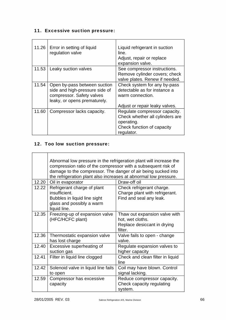
28/01/2005 REV. 03 Sabroe Refrigeration A/S, Marine Division 66
11. Excessive suction pressure: 11.26
Error in setting of liquid regulation valve
Liquid refrigerant in suction line. Adjust, repair or replace expansion valve.
11.53 Leaky suction valves See compressor instructions. Remove cylinder covers; check valve plates. Renew if needed.
11.54 Open by-pass between suction side and high-pressure side of compressor. Safety valves leaky, or opens prematurely.
Check system for any by-pass detectable as for instance a warm connection. Adjust or repair leaky valves.
11.60 Compressor lacks capacity. Regulate compressor capacity. Check whether all cylinders are operating. Check function of capacity regulator.
12. Too low suction pressure:
Abnormal low pressure in the refrigeration plant will increase the compression ratio of the compressor with a subsequent risk of damage to the compressor. The danger of air being sucked into the refrigeration plant also increases at abnormal low pressure.
12.20 Oil in evaporator Draw-off oil 12.22 Refrigerant charge of plant
insufficient. Bubbles in liquid line sight glass and possibly a warm liquid line.
Check refrigerant charge. Charge plant with refrigerant. Find and seal any leak.
12.35 Freezing-up of expansion valve (HFC/HCFC plant)
Thaw out expansion valve with hot, wet cloths. Replace desiccant in drying filter.
12.36 Thermostatic expansion valve has lost charge
Valve fails to open - change valve.
12.40 Excessive superheating of suction gas
Regulate expansion valves to higher capacity
12.41 Filter in liquid line clogged Check and clean filter in liquid line
12.42 Solenoid valve in liquid line fails to open
Coil may have blown. Control signal lacking.
12.59 Compressor has excessive capacity
Reduce compressor capacity. Check capacity regulating system.

28/01/2005 REV. 03 Sabroe Refrigeration A/S, Marine Division 67
13. Oil temperature too low: 13.15
Too little oil in compressor
Top up compressor with oil and investigate cause of oil consumption
13.18 Oil foams in compressor See point 18 13.49 Oil pump defective Repair or replace 13.50 Bearings worn Repair or replace 13.55 Oil filter clogged Change filter cartridge 14. Excessive discharge pipe temperature:
If, after approx. 1 hour’s operation, the discharge pipe temperature is more than 10°C higher than indicated in the table, the error may be due i.a. to:
14.21 Excessive suction temperature as result of reduced refrigerant supply to evaporator (extensive superheating) owing to insufficient refrigerant charge
Check refrigerant charge
14.22 Excessive suction temperature as result of reduced refrigerant supply to evaporator (extensive superheating) owing to incorrectly adjusted liquid regulating valves
Check thermostatic expansion valves
14.52 Leaky discharge valves Leaking discharge valves gives rise to generation of heat. Change defective valves.
14.54 Open by-pass between high and low-pressure side of compressor, e.g. leaky safety valve
Localize by-pass and remedy any leakages.
15. Too low discharge pipe temperature: 15.26
Low suction temperature as result of overflow of liquid refrigerant from evaporator
Adjust liquid regulating valve. Increase superheating.

28/01/2005 REV. 03 Sabroe Refrigeration A/S, Marine Division 68
16. Excessive oil temperature:
During operation, the temperature of the compressor crankcase must be 40-70°C. When working with R717 and R22, it may be necessary to supply the compressor with oil cooling.
See point 14. 17. Oil level in crankcase falling:
Where HFC/HCFC refrigerants are used, there will be some blending of refrigerant and oil during the initial operating period. It may therefore prove necessary to top up the oil after initial start-up of the plant. Note: The oil level must always be visible in the oil level sight glass on the compressor.
17.20 Filter in solenoid valve or nozzle in oil return line clogged
Oil return pipe must be warm during operations. Clean filter.
17.26 Liquid in suction line and crankcase may cause foaming in oil and thus increase oil consumption
Examine evaporator system and check superheating of suction gas.
17.51 Worn-out piston rings or cylinders
Renew piston rings and, if need be, renew pistons and cylinder linings.
17.57 Solenoid valve in oil return line defective
Coil in solenoid valve defective - Replace coil - Electrical control signal lacking

28/01/2005 REV. 03 Sabroe Refrigeration A/S, Marine Division 69
18. Heavy oil foaming in crankcase: 18.26
Liquid in suction line
See 17.26
18.61 Too much refrigerant dissolved in oil
Before starting compressor, heating element must have been on for at least 8 hours in order to boil refrigerant out of oil. During start-up phase, capacity should be connected at a slow rate to prevent a sudden drop of pressure on suction side with resultant foaming. Under normal operating conditions, compressor should operate under as stable pressure conditions as possible
19. Crankcase "sweating" or frosting up: 19.26
Liquid in suction line
See 17.26
19.37 Expansion valve sensor misplaced
Check positioning of expansion valve sensor - cf. instructions for expansion valve
19.39 Liquid regulating valve or float valve producing too much liquid
Increase superheating on thermostatic expansion valve
20. Capacity regulation oscillating: 20.18
Oil foaming in crankcase
See point 18
21. Impossible to bleed plant: 21.43
Solenoid valve leaky
Pinpoint and seal leak, or change leaky component
21.51 Defective piston rings Check and replace any defective parts
21.52 Defective discharge valves Check and replace any defective parts
21.53 Defective suction valves Check and replace any defective parts

28/01/2005 REV. 03 Sabroe Refrigeration A/S, Marine Division 70
Alignment of Unit When using vibration dampers, the machine room floor is assumed to have the necessary carrying capacity and to be level enough to enable adjustment of the vibration dampers. Alignment of Compressor with Base Frame Check that the entire footing of the compressor makes full contact with the milled-off faces of the base frame. Perform this check with the bolts loosened. If slips occur at one or more resting surfaces, shim up before tightening. If unaligned, there is a risk of stresses occurring in the compressor frame, which will damage the bearings. Alignment of Motor with Base Frame Check the contact faces of the motor against the base frame in the same way as for the compressor. Stresses from Pipe Connections In order to prevent stress being transmitted from pipe connections between unit and plant, pipes must be placed in such a way that compressive stresses or tensile strains are not generated in the event of expansions or contractions due to temperature changes. Steel piping expands approx. 1 mm per metre per 100°C.
28/01/2005 REV. 03 Sabroe Refrigeration A/S, Marine Division 71
V-belt Drive for SBO Reciprocating Compressors In case your SABROE compressor is belt-driven, use drive belts type SPA to calculate total length of V-belts: ((D1 x π + D2 x π) / 2) + 2 x C D1 = diameter of motor pulley D2 = diameter of compressor pulley C = distance between motor and compressor shaft Mounting of V-belts • Before mounting of V-belts the pulley tracks should be thoroughly cleaned of oil or dirt
as well as checked for any grooves and bruises.
• Move the motor sufficiently to allow the belts to be fitted without having to apply force. Never force the belts over the pulleys as the power transmitting fibres can be damaged and the life of the belts considerably reduced.
• After fitting of the V-belts compressor and motor are once more pulled apart and aligned by means of a straightedge. The tracks must be flush with one another and the shafts completely parallel.
• In order to obtain the best possible operating conditions the belt tension must be correct. This is checked by pressing the belts in between the pulleys by hand. The belts should be equally tight and an even pressure by hand only lower them 3 to 5 mm.
• Let the transmission run for a couple of minutes, then check the degree of tightness.
• It is important to inspect the tightening at regular intervals as indicated in the section: Servicing the reciprocating compressor.
• On replacing worn V-belts the whole set must be replaced.
• One set of V-belts must always be within the same tolerance group.
• Never use belt grease. Remember: The protecting guard should always be mounted whenever the belt drive is operating.

28/01/2005 REV. 03 Sabroe Refrigeration A/S, Marine Division 72
Ordering of Spare Parts When placing an order for spare parts, please state the following: 1. Shop No. All compressors are fitted with an identification plate, which states the type and shop No. of the compressor and indicates what refrigerant is to be used. 2. Part No. Spare parts drawings and parts lists inserted in an instruction manual identify spare parts by the following: a) Spare part No. - which is a reference number to facilitate finding a part in the drawing
and cross-referencing in the parts list or vice versa. b) Designation of the part. c) Part No. - a 7-digit number which refers to SABROE’s stores. When you order spare parts, please always advise at least the designation and part number. If you are in any doubt, add the spare part No., too. 3. Forwarding Instructions When ordering spares, please advise the forwarding address, and the address to which the invoice should be sent. If appropriate, please state the name of your local bank, the way in which you want the goods transported and required delivery date. 4. Classification Certificate If you require a certificate from a Classification Society, please mark the order appropriately, as the inspection and issuing procedures take extra time and incur extra expenses. 5. Quotation No. If a quotation No. has been given during earlier correspondence, please refer to this when placing your order - it will help us to identify and execute your order quickly.

28/01/2005 REV. 03 Sabroe Refrigeration A/S, Marine Division 73
Spare part drawing for compressor type SBO21 and SBO22

28/01/2005 REV. 03 Sabroe Refrigeration A/S, Marine Division 74
Spare part drawing for compressor type SBO41, SBO42, SBO43
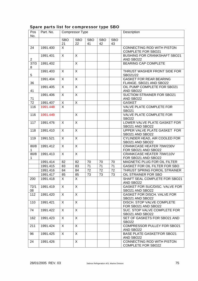
28/01/2005 REV. 03 Sabroe Refrigeration A/S, Marine Division 75
Spare parts list for compressor type SBO Pos No.
Part. No. Compressor Type Description
SBO 21
SBO22
SBO41
SBO42
SBO43
24 1991.400 X CONNECTING ROD WITH PISTON COMPLETE FOR SBO21
2
1991.401 X X BUSHING FOR CRANKSHAFT SBO21 AND SBO22
37/38
1991.402 X BEARING CAP COMPLETE
5
1991.403 X X THRUST WASHER FRONT SIDE FOR SBO21/22
36
1991.404 X X GASKET FOR REAR BEARING FLANGE. SBO21 AND SBO22
41
1991.405 X X OIL PUMP COMPLETE FOR SBO21 AND SBO22
71
1991.406 X X SUCTIOM STRAINER FOR SBO21 AND SBO22
72 1991.407 X X GASKET 116 1991.448 X VALVE PLATE COMPLETE FOR
SBO21 116 1991.449 X VALVE PLATE COMPLETE FOR
SBO22 117 1991.476 X X LOWER VALVE PLATE GASKET FOR
SBO21 AND SBO22 118 1991.410 X X UPPER VALVE PLATE GASKET FOR
SBO21 AND SBO22 119 1991.521 X X CYLINDER HEAD, AIR COOLED FOR
SBO21 AND SBO22 80/81
1991.412 X X CRANKCASE HEATER 70W/230V FOR SBO21 AND SBO22
80/81
1991.413 X X CRANKCASE HEATER 70W/110V FOR SBO21 AND SBO22
1991.414 82 82 70 70 70 MAGNETIC PLUG FOR OIL FILTER 1991.415 83 83 71 71 71 GASKET FOR OIL FILTER FOR SBO 1991.416 84 84 72 72 72 THRUST SPRING FOROIL STRAINER 1991.417 85 85 73 73 73 OIL STRAINER FOR SBO 200 1991.418 X X SHAFT SEAL COMPLETE FOR SBO21
AND SBO22 72/108
1991.419 X X GASKET FOR SUC/DISC. VALVE FOR SBO21 AND SBO22
112 1991.420 X X GASKET FOR DISCH. VALVE FOR SBO21 AND SBO22
110 1991.421 X X DISCH. STOP VALVE COMPLETE FOR SBO21 AND SBO22
74 1991.422 X X SUC. STOP VALVE COMPLETE FOR SBO21 AND SBO22
162 1991.423 X X SET OF GASKETS FOR SBO21 AND SBO22
211 1991.424 X X COMPRESSOR PULLEY FOR SBO21 AND SBO22
96 1991.425 X X BASE PLATE GASKETFOR SBO21 AND SBO22
24 1991.426 X CONNECTING ROD WITH PISTON COMPLETE FOR SBO22

28/01/2005 REV. 03 Sabroe Refrigeration A/S, Marine Division 76
Pos no.
Part. No. Compressor Type Description
SBO21
SBO22
SBO41
SBO42
SBO43
37/38/41
1991.427 X BEARING CAP COMPLETE INCL. OIL PUMP FOR SBO21
38 1991.428 X X BEARING BUSH SBO21/22 86 1991.429 X X OIL RETURN SYSTEM FOR SBO21/22 200 1991.430 X X SHAFT SEAL COMPLETE FOR
SBO21/22 R717 / R134a
207 1991.431 X X GASKET F. SHAFT SEAL COVER SBO21/22
2 1991.450 X X X BEARING BUSH (MOTOR SIDE) FOR SBO41/42/43
3 1991.451 X X X BEARING BUSH (CRANK. SIDE) SBO41/42/43
5 1991.452 X X X THRUST WASHER (CRANK SIDE) SBO41/42/43
12 1991.453 X CONNECTING ROD WITH PISTON COMPLETE SBO41
12 1991.454 X CONNECTING ROD WITH PISTON COMPLETE SBO42
12 1991.455 X CONNECTING ROD WITH PISTON COMPLETE SBO43
24 1991.456 X BEARING CAP COMPLETE 24 1991.457 X X BEARING CAP COMPLETE 25 1991.458 X X X BUSHING FOR CRANKSHAFT
SBO41/42/43 26 1991.459 X X THRUST WASHER SBO42/43 23 1991.460 X X X REAR BEARING FLANGE
GASKETFOR SBO41/42/43 57 1991.461 X X X SUCTION STRAINER FOR
SBO41/42/43 58 1991.462 X X X GASKET FOR SUC. VALVES
BO41/42/43 60 1991.463 X X X SUC. STOP VALVE COMPLETE FOR
SBO41/42/43 94 1991.464 X X X DISCH. STOP VALVE COMPLETE
FOR SBO41/42/43 68 1991.465 X X X CRANKCASE HEATER 100W/230V
SBO41/42/43 68 1991.466 X X X CRANKCASE HEATER 100W/110V
SBO41/42/43 74 1991.467 X X X OIL RELIEF VALVE FOR SBO41/42/43 1991.468 93 93 77 77 77 SIGHT GLASS FOR SBO 1991.469 92 92 76 76 76 O-RING FOR SIGHT GLASS 28 1991.470 X X X OIL PUMP COMPLETE FOR
SBO41/42/43 29 1991.471 O-RING FOR OIL PUMP 100 1991.472 X VALVE PLATE COMPLETE SBO41
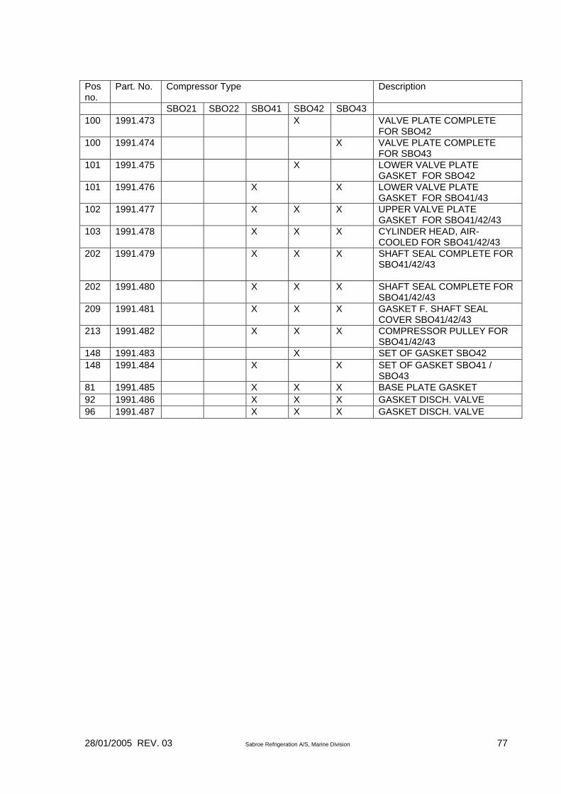
28/01/2005 REV. 03 Sabroe Refrigeration A/S, Marine Division 77
Pos no.
Part. No. Compressor Type Description
SBO21 SBO22 SBO41 SBO42 SBO43 100 1991.473 X VALVE PLATE COMPLETE
FOR SBO42 100 1991.474 X VALVE PLATE COMPLETE
FOR SBO43 101 1991.475 X LOWER VALVE PLATE
GASKET FOR SBO42 101 1991.476 X X LOWER VALVE PLATE
GASKET FOR SBO41/43 102 1991.477 X X X UPPER VALVE PLATE
GASKET FOR SBO41/42/43 103 1991.478 X X X CYLINDER HEAD, AIR-
COOLED FOR SBO41/42/43 202 1991.479 X X X SHAFT SEAL COMPLETE FOR
SBO41/42/43
202 1991.480 X X X SHAFT SEAL COMPLETE FOR SBO41/42/43
209 1991.481 X X X GASKET F. SHAFT SEAL COVER SBO41/42/43
213 1991.482 X X X COMPRESSOR PULLEY FOR SBO41/42/43
148 1991.483 X SET OF GASKET SBO42 148 1991.484 X X SET OF GASKET SBO41 /
SBO43 81 1991.485 X X X BASE PLATE GASKET 92 1991.486 X X X GASKET DISCH. VALVE 96 1991.487 X X X GASKET DISCH. VALVE


