17
INSTRUCTION MANUAL FOR THE THERMOCOUPLE ATTACHMENT UNIT (TAU) Model Number: 41756 (100 – 125Vac) 41757 (220 – 240Vac) Manufactured in the United Kingdom
INSTRUCTION MANUAL
FOR THE
THERMOCOUPLE ATTACHMENT UNIT (TAU)
Model Number: 41756 (100 – 125Vac)
41757 (220 – 240Vac)
Manufactured in the United Kingdom

Ref:TAU/MANUAL Issue: 09/2008
Page 2 of 17
CONTENTS Chapter Page Specification 3 What the TAU does 4 Functions 5 Electrical schematic drawing 6 Safety 7 Making a thermocouple 8 Operation of the TAU 9 Battery monitor 10 Maintenance 11 Fault finding 12 Ordering replacement parts and spares 15 Replacement parts list 16 Warranty 17 Date of issue Sept 2008 © 2008 Stork Thermal Inspection Services (STIS) All rights reserved. No part of this document may be reproduced, stored in retrieval system, or transmitted in any form by any means, electronic, mechanical, photocopying, recording or otherwise without the prior, written permission of STIS.
Ref:TAU/MANUAL Issue: 09/2008
Page 3 of 17
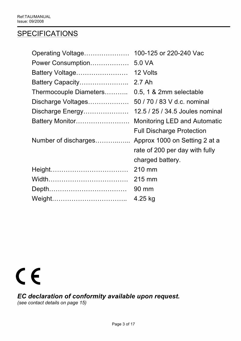
SPECIFICATIONS Operating Voltage………………… 100-125 or 220-240 Vac Power Consumption……………… 5.0 VA Battery Voltage…………………… 12 Volts Battery Capacity………………….. 2.7 Ah Thermocouple Diameters……….. 0.5, 1 & 2mm selectable Discharge Voltages………………. 50 / 70 / 83 V d.c. nominal Discharge Energy………………… 12.5 / 25 / 34.5 Joules nominal
Battery Monitor……………………. Monitoring LED and Automatic Full Discharge Protection
Number of discharges………..…... Approx 1000 on Setting 2 at a rate of 200 per day with fully charged battery.
Height……………………………… 210 mm Width………………………………. 215 mm Depth……………………………… 90 mm Weight…………………………….. 4.25 kg
EC declaration of conformity available upon request. (see contact details on page 15)

Ref:TAU/MANUAL Issue: 09/2008
Page 4 of 17
WHAT THE TAU DOES
Stork’s Thermocouple Attachment Unit (TAU) provides a reliable and extremely accurate method of temperature measurement of pre and post weld heat treatment processes by the direct attachment of thermocouples to the workpiece known as the capacitive discharge method.
Previous methods of thermocouple attachment where the two conductors, comprised of two thermocouple materials, were welded or brazed/soldered at the tip to make a ‘hot’ junction, lead to large inaccuracies in the temperatures being recorded. The solution is to produce the ‘hot’ junction by welding the conductor wires directly and independently on to the metal surface as facilitated by Stork’s TAU. By adopting this capacitive discharge method of welding the conductors on to the metal surface, serious errors arising from the proximity of a heating source are avoided. A rechargeable battery provides power to flash-discharge, butt-weld the ends of the thermocouple wires directly to the surface of a welded workpiece. The wires are spaced 6 mm maximum apart. This causes the workpiece material itself to become the junction of the thermocouple. There can therefore be no inaccuracy in the temperature measurement. Heating elements can lay on top of any part of the thermocouple junction or wires without any adverse affects on temperature measurement.
Ref:TAU/MANUAL Issue: 09/2008
Page 5 of 17
H
D C B A
G
F
I
E
J K
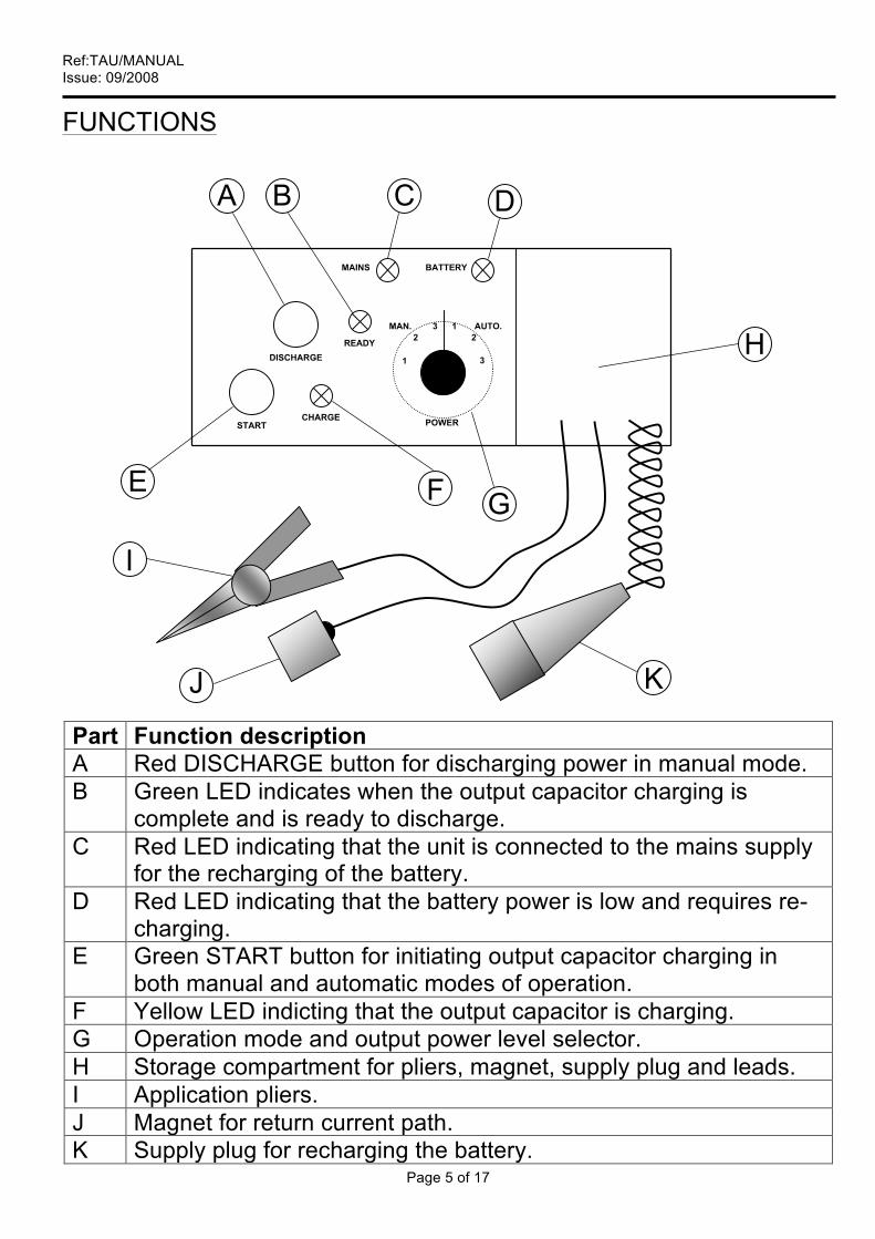
FUNCTIONS
Part Function description A Red DISCHARGE button for discharging power in manual mode. B Green LED indicates when the output capacitor charging is
complete and is ready to discharge. C Red LED indicating that the unit is connected to the mains supply
for the recharging of the battery. D Red LED indicating that the battery power is low and requires re-
charging. E Green START button for initiating output capacitor charging in
both manual and automatic modes of operation. F Yellow LED indicting that the output capacitor is charging. G Operation mode and output power level selector. H Storage compartment for pliers, magnet, supply plug and leads. I Application pliers. J Magnet for return current path. K Supply plug for recharging the battery.
POWER
3
1 2
3 2
MAINS BATTERY
DISCHARGE
CHARGE START
READY
1
MAN. AUTO.

Ref:TAU/MANUAL Issue: 09/2008
Page 6 of 17
ELECTRICAL SCHEMATIC DRAWING
Wire Colour/Termination Key CO1 1 - Yellow 2 - Violet 3 - Green 4 - Green CO2 1 - Orange 2 - Orange 3 - Red 4 - Black CO3 1 - Pink (Cap +ve) 2 - Grey (Cap –ve) 3 - Blue 4 - Brown
1 2 3 4
1 2 3 4
PCB 3 CO3
CO2 CO1
Start Switch Discharge Switch
Capacitor
Thyristor
Pliers
Magnet
Live
Neutral
Earth 2
Mains Supply INPUT
Fuse
4
1
Ref:TAU/MANUAL Issue: 09/2008
Page 7 of 17
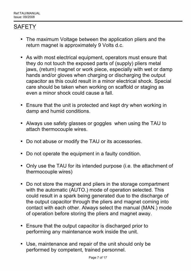
SAFETY • The maximum Voltage between the application pliers and the
return magnet is approximately 9 Volts d.c. • As with most electrical equipment, operators must ensure that
they do not touch the exposed parts of (supply) pliers metal jaws, (return) magnet or work piece, especially with wet or damp hands and/or gloves when charging or discharging the output capacitor as this could result in a minor electrical shock. Special care should be taken when working on scaffold or staging as even a minor shock could cause a fall.
• Ensure that the unit is protected and kept dry when working in
damp and humid conditions. • Always use safety glasses or goggles when using the TAU to
attach thermocouple wires. • Do not abuse or modify the TAU or its accessories.
• Do not operate the equipment in a faulty condition.
• Only use the TAU for its intended purpose (i.e. the attachment of
thermocouple wires) • Do not store the magnet and pliers in the storage compartment
with the automatic (AUTO.) mode of operation selected. This could result in a spark being generated due to the discharge of the output capacitor through the pliers and magnet coming into contact with each other. Always select the manual (MAN.) mode of operation before storing the pliers and magnet away.
• Ensure that the output capacitor is discharged prior to
performing any maintenance work inside the unit. • Use, maintenance and repair of the unit should only be
performed by competent, trained personnel.
Ref:TAU/MANUAL Issue: 09/2008
Page 8 of 17
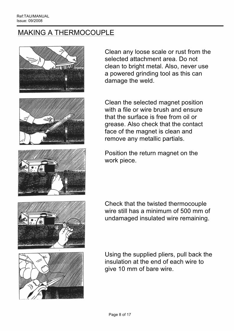
MAKING A THERMOCOUPLE
Clean any loose scale or rust from the selected attachment area. Do not clean to bright metal. Also, never use a powered grinding tool as this can damage the weld. Clean the selected magnet position with a file or wire brush and ensure that the surface is free from oil or grease. Also check that the contact face of the magnet is clean and remove any metallic partials. Position the return magnet on the work piece. Check that the twisted thermocouple wire still has a minimum of 500 mm of undamaged insulated wire remaining. Using the supplied pliers, pull back the insulation at the end of each wire to give 10 mm of bare wire.
Ref:TAU/MANUAL Issue: 09/2008
Page 9 of 17
Note: to avoid serious damage to sensitive temperature control and recording instruments, thermocouples must be disconnected from all apparatus whilst using the TAU to attaché thermocouple wires to the workpiece. OPERATION
• Before switching the unit on, select the operation mode to manual or auto and the required power level for the diameter of thermocouple wire to be used by turning the POWER switch to one of the following settings:
1 - for 0.5 mm diameter thermocouple wire 2 - for 1.0 mm diameter thermocouple wire 3 - for 2.0 mm diameter thermocouple wire
• To switch the unit on, press the START button. Note: the unit
will automatically switch off after approximately 3 minutes of no use. This avoids the need for an OFF switch and prevents the unintentional running down of the battery by forgetting to turn the unit off.
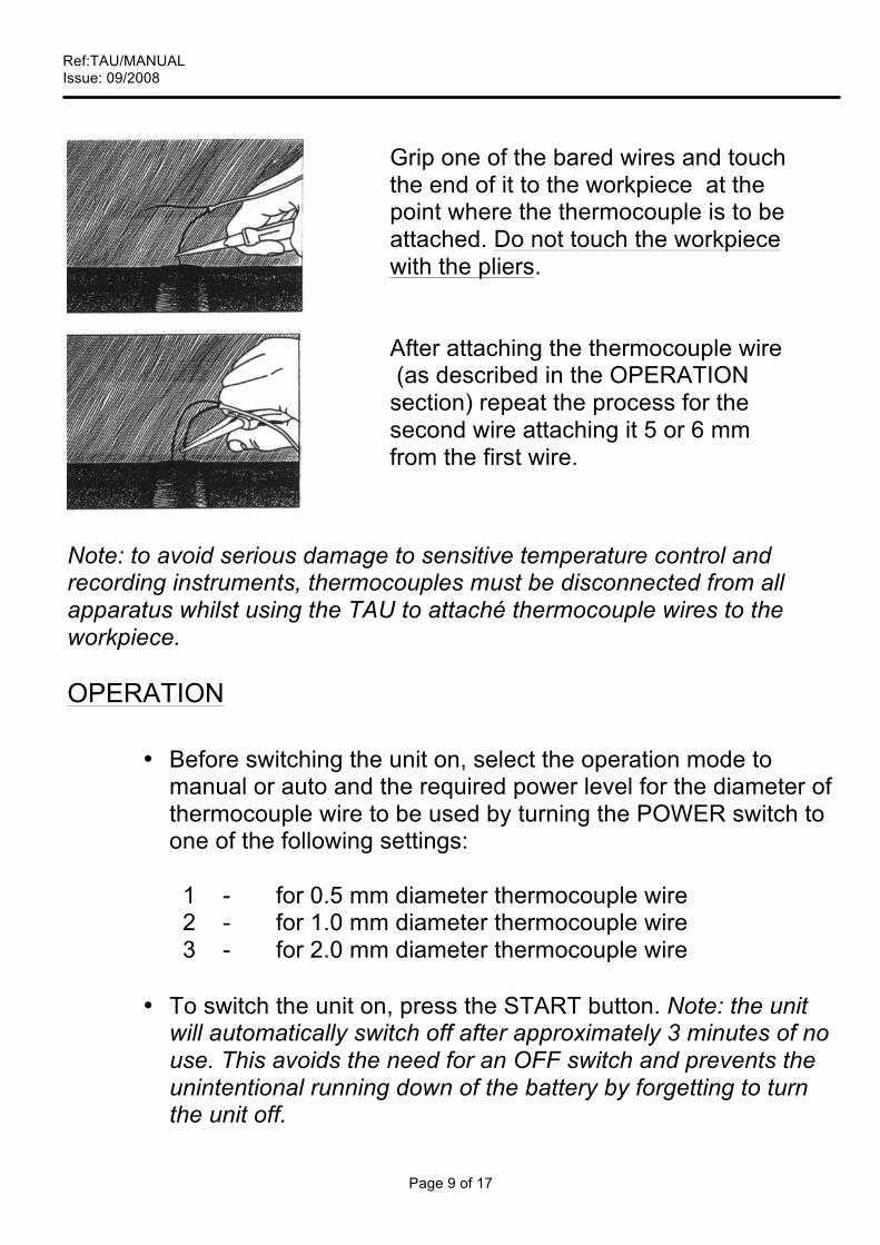
Grip one of the bared wires and touch the end of it to the workpiece at the point where the thermocouple is to be attached. Do not touch the workpiece with the pliers. After attaching the thermocouple wire (as described in the OPERATION section) repeat the process for the second wire attaching it 5 or 6 mm from the first wire.

Ref:TAU/MANUAL Issue: 09/2008
Page 10 of 17
• To enable the unit to be continuously used the Discharge
capacitor is automatically charged after every discharge. Note: The unit can be used without re-charge until the BATTERY LED is continuously illuminated.
• There are two modes of operation of discharging, AUTO and
MANUAL. The MANUAL mode requires you to press the DISCHARGE button when you are ready to discharge the thermocouple, whereas the AUTO mode will automatically discharge the thermocouple after it has been in contact with the workpiece for approximately 2 seconds.
• After the thermocouple has been discharged, if the pliers are
still in contact with the workpiece, e.g. for bending over of the thermocouple wires, an internal monitor circuit will prevent the TAU. from re-charging until the pliers are removed.
• Even though the TAU. is charging the internal capacitor up to
voltages of 80 volts, which could give a shock if touched, the pliers and magnet only have less than 9 Volts across them until the pliers touch the workpiece. This removes the possibility of an operator giving himself a shock when pressing the DISCHARGE button.
BATTERY MONITOR
• The condition of the internal battery is monitored continuously, when in operation, by the BATTERY LED circuit.
• As the battery becomes discharged the BATTERY LED will
become continuously illuminated.
• If the BATTERY LED illuminates only during the charging of the capacitor it is advisable to re-charge the internal battery as soon as possible by plugging the supply mains cable into a 110V supply.

Ref:TAU/MANUAL Issue: 09/2008
Page 11 of 17
• It is reasonable to anticipate 1000 discharges from a fully
charged battery (on setting 2.). A normal period of time for battery re-charge is 12-18 hours.
• Charging current is 400 mA maximum.
• After the initial illumination of the LED it is still possible, with a
battery in good condition, to achieve approximately 200 discharges on power setting 2.
• It is not possible, by use, to fully discharge the internal battery
as a built in monitor circuit will switch off the unit at a preset minimum voltage.
• Note: If left unused for long periods, the rechargeable battery
may not accept a full charge immediately. If after charging the ready LED does not illuminate, place the TAU on charge for 14 hours and then fully discharge the battery. Repeat 2 or 3 times after which the battery should accept a full charge.
MAINTENANCE
The TAU requires little maintenance as it incorporates solid-state devices, however, we recommend that the following checks be carried out every 6 months:- • Examine supply plug and all flexible leads for damage or wear
and replace as necessary. • Inspect condition of the application pliers and return magnet,
clean necessary and replace if damaged or worn. • Check that the selector switch and push buttons are functioning
and free to operate and replace if necessary. • Check that the LEDs are functioning correctly and replace if
necessary.
Ref:TAU/MANUAL Issue: 09/2008
Page 12 of 17
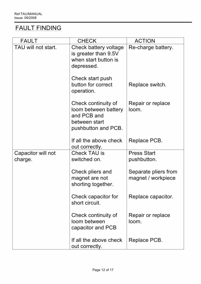
FAULT FINDING
FAULT CHECK ACTION TAU will not start. Check battery voltage
is greater than 9.5V when start button is depressed. Check start push button for correct operation. Check continuity of loom between battery and PCB and between start pushbutton and PCB. If all the above check out correctly.
Re-charge battery. Replace switch. Repair or replace loom. Replace PCB.
Capacitor will not charge.
Check TAU is switched on. Check pliers and magnet are not shorting together. Check capacitor for short circuit. Check continuity of loom between capacitor and PCB If all the above check out correctly.
Press Start pushbutton. Separate pliers from magnet / workpiece Replace capacitor. Repair or replace loom. Replace PCB.
Ref:TAU/MANUAL Issue: 09/2008
Page 13 of 17
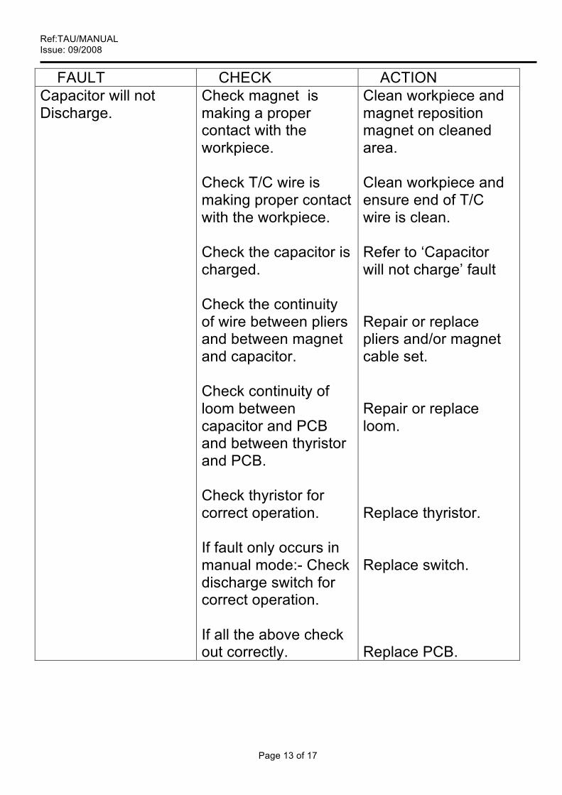
FAULT CHECK ACTION Capacitor will not Discharge.
Check magnet is making a proper contact with the workpiece. Check T/C wire is making proper contact with the workpiece. Check the capacitor is charged. Check the continuity of wire between pliers and between magnet and capacitor.
Check continuity of loom between capacitor and PCB and between thyristor and PCB. Check thyristor for correct operation. If fault only occurs in manual mode:- Check discharge switch for correct operation. If all the above check out correctly.
Clean workpiece and magnet reposition magnet on cleaned area. Clean workpiece and ensure end of T/C wire is clean. Refer to ‘Capacitor will not charge’ fault Repair or replace pliers and/or magnet cable set. Repair or replace loom.
Replace thyristor. Replace switch. Replace PCB.
Ref:TAU/MANUAL Issue: 09/2008
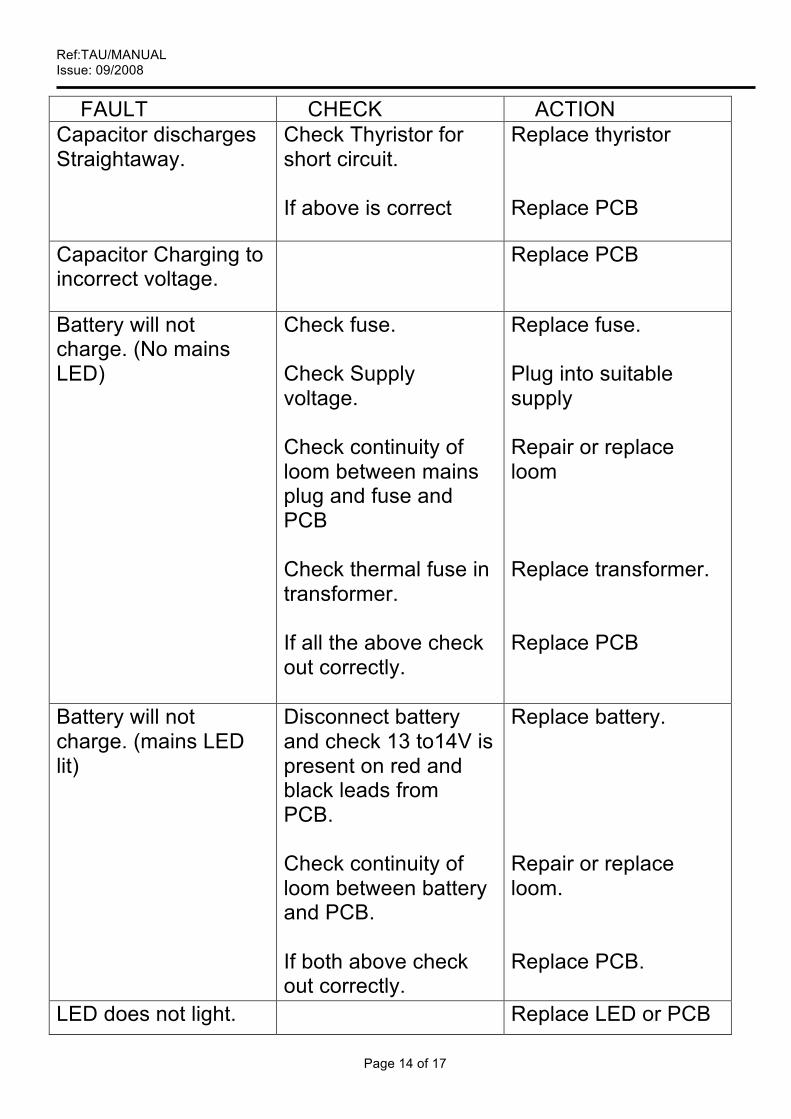
Page 14 of 17
FAULT CHECK ACTION Capacitor discharges Straightaway.
Check Thyristor for short circuit. If above is correct
Replace thyristor Replace PCB
Capacitor Charging to incorrect voltage.
Replace PCB
Battery will not charge. (No mains LED)
Check fuse. Check Supply voltage. Check continuity of loom between mains plug and fuse and PCB Check thermal fuse in transformer. If all the above check out correctly.
Replace fuse. Plug into suitable supply Repair or replace loom Replace transformer. Replace PCB
Battery will not charge. (mains LED lit)
Disconnect battery and check 13 to14V is present on red and black leads from PCB. Check continuity of loom between battery and PCB. If both above check out correctly.
Replace battery.
Repair or replace loom. Replace PCB.
LED does not light. Replace LED or PCB
Ref:TAU/MANUAL Issue: 09/2008
Page 15 of 17
ORDERING REPLACEMENT PARTS AND SPARES
When ordering any spare parts it is recommended that you refer to:
(a) Type of unit described herein. (b) Stork Works Order reference number – (c) Date supplied – (d) Your original order reference – (e) Your organisation full name – (f) Unit Serial number – All orders should be marked for the attention of ‘Equipment Sales Department’ at the following address:
Stork Thermal Inspection Services Units 21 - 24
Slaidburn Crescent Southport
Merseyside PR9 9YF
United Kingdom Tel. No. +44 (0)1704 215600 Fax No. +44 (0)1704 215601 Email: [email protected]
Web: www.stork.com/stis
Ref:TAU/MANUAL Issue: 09/2008
Page 16 of 17
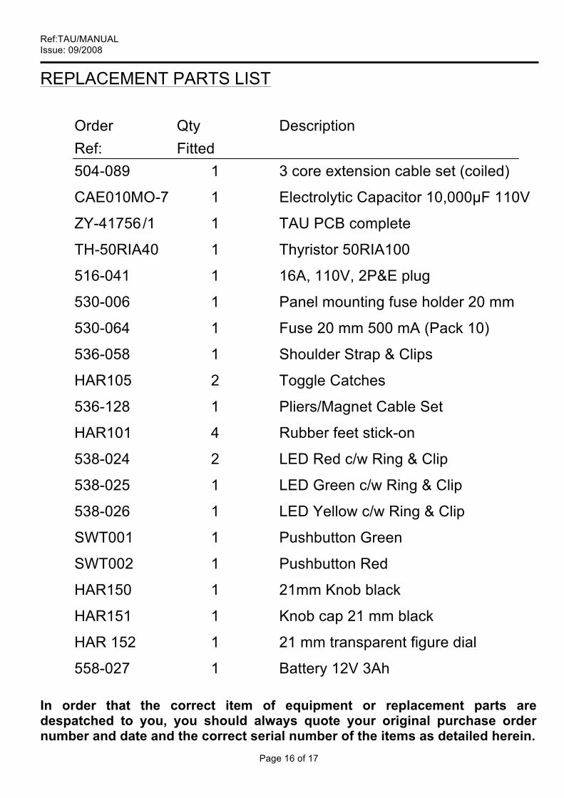
REPLACEMENT PARTS LIST
Order Qty Description Ref: Fitted 504-089 1 3 core extension cable set (coiled)
CAE010MO-7 1 Electrolytic Capacitor 10,000µF 110V
ZY-41756 /1 1 TAU PCB complete
TH-50RIA40 1 Thyristor 50RIA100
516-041 1 16A, 110V, 2P&E plug
530-006 1 Panel mounting fuse holder 20 mm
530-064 1 Fuse 20 mm 500 mA (Pack 10)
536-058 1 Shoulder Strap & Clips
HAR105 2 Toggle Catches
536-128 1 Pliers/Magnet Cable Set
HAR101 4 Rubber feet stick-on
538-024 2 LED Red c/w Ring & Clip
538-025 1 LED Green c/w Ring & Clip
538-026 1 LED Yellow c/w Ring & Clip
SWT001 1 Pushbutton Green
SWT002 1 Pushbutton Red
HAR150 1 21mm Knob black
HAR151 1 Knob cap 21 mm black
HAR 152 1 21 mm transparent figure dial
558-027 1 Battery 12V 3Ah In order that the correct item of equipment or replacement parts are despatched to you, you should always quote your original purchase order number and date and the correct serial number of the items as detailed herein.
Ref:TAU/MANUAL Issue: 09/2008
Page 17 of 17
WARRANTY General Stork Thermal Inspection Services (STIS) guarantee that, subject to the conditions under herein, we will replace the goods described or repair the same, for a period of six months from the date of despatch, for any items with defects caused by faulty materials or workmanship.
STIS shall not incur any liability under the above warranty unless:-
• STIS is promptly notified in writing upon discovery by the customer
that such goods do not confirm to the warranty. • The alleged defective goods are returned to STIS, carriage prepaid. • Examination by STIS of the good confirms that the alleged defect
exists and has not been caused by mis-use, neglect, repair, or by alteration or accident.
STIS shall be limited to replacing or repairing any goods returned within six months of the date of despatch. Our liability under the warranty, shall be limited to supply on an FOB, country of origin basis, for any parts found to be defective.
Our warranty will not apply to any consumable items or parts requiring replacement caused by normal wear and tear. To dispose of this unit telephone +44 (0)1704 215600
Warranty Replacement Procedure All parts shipped, whether to replace parts which failed within the warranty period or not, will be invoices at full F.O.B. prices. The parts replaced should then be returned to our factory, transportation prepaid, for our examination. Credit will be issued if our inspection indicates that failure occurred during the warranty period.


