21
Instruction Manual For Thermistor Gauge GT-340A Myers Vacuum RD # 2 Box 247A Kittanning, PA 16201 Phone: 724-545-8331 Fax: 724-545-8332
Instruction Manual ForThermistor Gauge
GT-340A
Myers VacuumRD # 2 Box 247AKittanning, PA 16201Phone: 724-545-8331Fax: 724-545-8332

Myers Vacuum Instruction ManualMarch 21, 2003 GT-340A No. 9-46-A
Page 2 of 21
TABLE OF CONTENTS
SECTION DESCRIPTION
1.0 INTRODUCTION
1.1 Product Description1.2 Operating Principles1.3 Specifications
2.0 INSTALLATION
2.1 Unpacking2.2 Installing the Pressure Sensing Tube2.3 Electrical Connections2.4 Adding A Second Optional Sensing Station2.5 Connecting Pressure Recorder2.6 Connecting Load To Relay Control Unit
3.0 OPERATION
3.1 Measuring Pressure3.2 Calibration Correction for Common Gases3.3 Adjusting Relay Control Trip Point-Type GT-345A Gauge3.4 Adjusting Relay Hysteresis – Type GT-345A Gauge3.5 Leak Detection Techniques3.6 Operations of the Leak Detect Feature
4.0 MAINTENANCE
4.1 Cleaning the Sensing Tube4.2 Re-calibration
5.0 REPLACEMENT PARTS LISTS
6.0 ACCESSORIES
7.0 SCHEMATIC
8.0 ASSISTANCE FROM MYERS VACUUM

Myers Vacuum Instruction ManualMarch 21, 2003 GT-340A No. 9-46-A
Page 3 of 21
THERMISTOR VACUUM GAUGETYPES GT-340A AND GT-345A
1.0 INTRODUCTION
1.1 Product Description
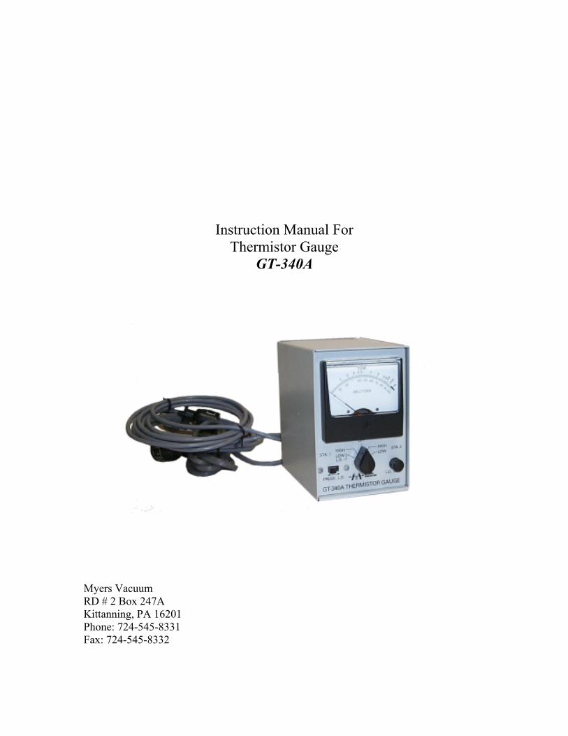
1.1.1 The Type GT-340 Thermistor Vacuum Gauge is a thermalconductivity type gauge using a bead thermistor as the sensingelement. Pressure from zero to atmosphere is covered on two-meter ranges. The gauge can be equipped with either one or twopressure sensing stations. Terminals are provided for recording theoutput of either or both stations, independent of the station selectorswitch position.
This gauge is equipped with a Leak Detect switch and adjustmentpotentiometer by means of which the gauge sensitivity can begreatly increased for purposes of hunting down leaks.
1.1.2 The GT-345A Controlling Type Thermistor Vacuum Gaugeconsists basically of a GT-340 Gauge Circuit plus a GT-005ARelay Control Unit, both mounted in a common cabinet. Thegauge circuit provides a signal to the GT-005 control circuit. Thissignal is amplified and used to drive a power relay, therebyproviding contacts, which switch in response to changes inpressure.
1.2 Operating Principles
The GT-340A Gauge Circuit consists of a voltage regulator whichsupplies a constant regulated voltage to a wheatstone bridge type detectorcircuit. One arm of the bridge contains the thermistor sensor, which isexposed to the vacuum to be measured. Normal current flow through thebridge heats the thermistor to approximately 190°C at pressures less than.001 torr. Increasing the pressure at the thermistor sensor causes itstemperature to decrease (and its resistance to increase), therebyunbalancing the bridge circuit. The pressure meter responds to the bridgeunbalance current and is calibrated in units of pressure.
Myers Vacuum Instruction ManualMarch 21, 2003 GT-340A No. 9-46-A
Page 4 of 21
When two pressure sensing stations are used, a double bridge is providedand the meter is switched from one bridge to the other in order to readpressure at the respective station. Both stations are continuouslyenergized whenever the gauge is turned on. Recorder terminals connect tothe output of each bridge.
In the GT-345A Controlling Gauge, the bridge output signal is connectedin series with a variable reference voltage, to one input of an operationalamplifier. The other input contains a positive feed-back network. Theoutput of the operational amplifier is further amplified and then used toenergize the power relay. Changing the reference voltage will change thepressure at which the relay will trip, and changing the-back ratio varies thehysteresis, or differential between pull-in and dropout, of the relay.
1.3 Specifications
1.3.1 GT-340A Thermistor Vacuum Gauge
Power Input 115/230 V 50/60 Hz 10 watts
Pressures ScalesLow Range 0-100 millitorr in 2 millitorr
incrementsHigh Range 0-ATM, non-linear scale
Number of SensingStations 1 or 2
Recorder Output 0-2.5V (approx.), availablecontinuously from either or bothstations, independent of range switchpositions. Recommended recorderimpedance, 50,000 ohms or higher.
Pressure Sensing Tube Type GT-034Tubulation VacuumSeal 1/8” pipe thread or .406” diameter
O-Ring sealing surface.

Myers Vacuum Instruction ManualMarch 21, 2003 GT-340A No. 9-46-A
Page 5 of 21
Electrical Connection Standard octal plug
Speed of Response Intial start-up, 30-40 sec.
(Time to reach 90% of 100 m torr step change ---final reading) 6 sec.
Line cord 9 ft. length, 3 wire, withGrounding plug
Tube Cord 10 ft. length*, with octal plug
Cabinet Dimensions 4" wide x 6" high x 6 1/2"deep For bench or rack mounting
*See Section 6.0, Accessories, for longer cord lengths.
1.3.2 GT-005A Relay Control Unit
Power Input 115/230 V 50/60 Hz 10W
Trip Point Adjustment Low Range 0 to 0.6 volts (0 to 100m Torr) High Range 0 to 2.75 volts ( 0 to ATM).
Hysteresis Adjustment Low Range .055 to .500 volts High Range 0.25 to 2.25 volts
Input Impendance Low Range 22K ohms High Range 122K ohms
Relay Contacts (Energized) SPDT, 3 amp, Contacts
Cabinet Dimensions 4" w x 6" h x 6-1/2" d **
**The GT-345A Gauge, which combines the GT-340A andGT-005A, is housed in a half-rack size cabinet 8" w x 6" h x 6-1/2" d.
`

Myers Vacuum Instruction ManualMarch 21, 2003 GT-340A No. 9-46-A
Page 6 of 21
2.0 INSTALLATION
2.1 Unpacking
Unpack and inspect the carton and contents for damage or shortages.Damages in transit are the normal responsibility of the TransportationCompany and should be reported to them.
2.2 Installing the Pressure Sensing Tube.
The tube may be installed in any position. However, mounting positioninfluences pressure reading above 10 torr. If this pressure range ifs ofinterest the tube should be mounted vertically with base up.
For accurate pressure response and freedom from zero drift, the tubeelements must remain clean. Therefor, the tube should be installed so s tominimize the entrance of oil vapor or process contaminants.
Install the sensing tube in any of the following ways:
2.2.1 Thread the tubulation into a mating 1/8” pipe thread opening in thevacuum system. Seal the threads with Teflon tape, Celvaseal LeakSealant (Part No. 271375), or other low vapor pressure sealingmaterial.
Or
2.2.2 Use a type CGB compression connector to form an easy-to-openvacuum seal. This connector is basically an elastomer bushingenclosed in a metal envelope which threads into a 1/2” NPT tappedhole. Use connector (Part No. 61083), with 3/8” bushing (Part No.61081-2).
Or
2.2.3 Place the end of the tubulation tightly against a similar-sized tubeinstalled in the system and enclose the butt joint in a short piece ofheavy-wall rubber vacuum tubing. Put a thin coat of vacuumgrease, such as Celvacene-Medium, on the tubulation and thesystem connections. The grease lubricated the connecting partsand provides a vacuum seal.

Myers Vacuum Instruction ManualMarch 21, 2003 GT-340A No. 9-46-A
Page 7 of 21
2.3 Electrical Connections
Plug the tube cable into the sensing tube.
The gauge is factory wired for operation from a 115 volt power source.Plug the three-prong grounding type power cord into a suitable 115 volt,50/60 Hz outlet.
2.3.1 Operation from a 230 Volt Power Circuit
To adapt the unit for 230-Volt 50/60 Hz operation, make thefollowing adjustments:
1. Remove the four feet and slide the cover off the chassis.
2. On the GT-340A gauge unit, locate the taper pin connectoron the end of the white line cord wire. Transfer thisconnection from the 115V taper pin socket to the 230Vtaper pin socket.
3. On the GT-345A gauge, perform the operation in step 2. Inaddition, move the white inter-unit connecting wire fromtaper pin socket 115 to pin socket 230 in the GT-340 unit.Then, in the GT-005A unit, move the jumper wire from115V to 230V taper pin.
4. Replace the cover feet.
5. Change the voltage marking on the nameplate.
6. Replace the line cord plug with an approved 230-volt plug.
2.4 Adding A Second Optional Sensing Station
If the gauge has only one sensing tube, a second tube can be easilyinstalled as follows.
2.4.1 Remove the four feet slide the cover off the chassis.
Myers Vacuum Instruction ManualMarch 21, 2003 GT-340A No. 9-46-A
Page 8 of 21
2.4.2 Remove the plug from the blank hole in the rear panel, and installthe second station tube cable (Part No. 5505889-1). Secure inplace with strain relief busing (Part No. 19366-1). Plug into thethree taper pin connectors and solder into place the pins aremarked STA 2, Red, Green and White. Be sure are tight.
2.4.3 Replace the cover and feet.
The gauge is now ready for operation. No calibration is normally requiredwhen adding a second station.
2.5 Connecting Pressure Recorder.
A three pin jack located on the rear panel of the GT-340A gauge unit areintended for connecting pressure recorders or for providing a pressureresponsive signal to the GT-005A control unit. Use the wiring circuit inlocated on the rear of the unit when recording station 1 pressure.
To record station 2 pressure, make connections to “COM” and “STA“jacks. Both stations can be recorded simultaneously if desired, by using a2-point recorder. Recorder signal voltages are not affected by the positionof the range/selector switch on the GT-340A (except in the OFF position).
2.5 Connecting Load To Relay Control Unit
A relay-controlled output of the GT-005A unit is available at the 3 pinsocket on the rear panel. Relay contact connections are marked on thepanel. The relay contacts are rated at 125V AC, at 3 amperes.
The relay coil of the 005 is controlled by the signal from the gauge.Power must be supplied to the relay contacts.

Myers Vacuum Instruction ManualMarch 21, 2003 GT-340A No. 9-46-A
Page 9 of 21
3.0 OPERATION
3.1 Measuring Pressure
After proper installation and connection, the gauge may be turned on.Allow 1 minute for warm-up time. The thermistor gauge tubes are notharmed by operation at pressures up to full atmospheric pressure, but theselector switch should be in the High position.
NOTE: A meter overload protector is included in the circuit toprevent meter damage if the selector is switched to LOWwhile the pressure in the sensing tube is high. When firstturned on, the meter will peg up-scale for approx. 20seconds.
The pressure meter will indicate the pressure within the sensing tube inunits of “Torr” on the upper scale. The gauge is calibrated for dry air.When the meter indicates less than 0.1 torr, the selector should be movedto the “LOW” position, and the pressure read on the lower scale inmillitorr.
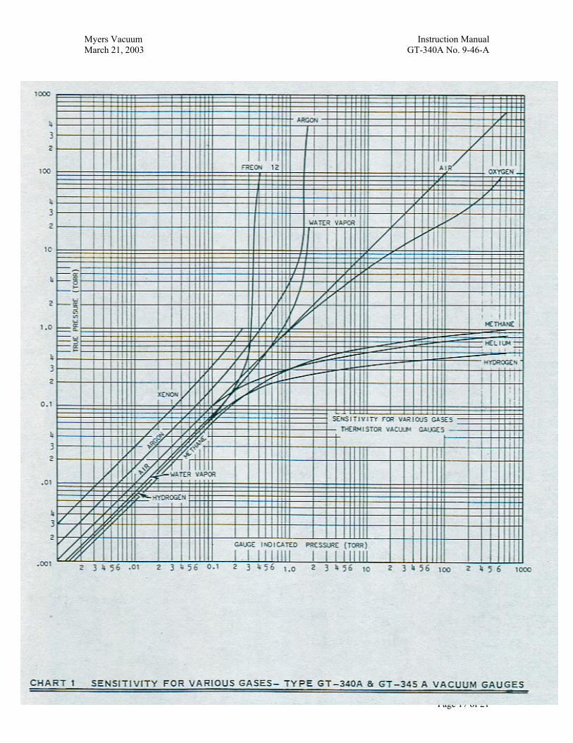
3.2 Calibration Correction For Common Gases
These gauges are calibrated for use in dry air. To determine the pressureof gases other than air, refer to graph 1.
3.3 Adjusting Relay Control Trip Point – Type GT-345A Gauge
The relay trip point is adjustable by means of the marked screwadjustment on the front panel. There are two ranges over which the GT-005A unit operated, as follows:
Low Range – zero to 0.6 volts. This range is used whencontrolling pressure below 100 mTorr.
High Range - Zero to 2.75 volts. This range is used whencontrolling pressure above 100 mTorr
Myers Vacuum Instruction ManualMarch 21, 2003 GT-340A No. 9-46-A
Page 10 of 21
The operating range can be selected by removing the cover and placing theblack signal wire in the GT-005 unit into the appropriate taper pin socked.Be sure taper pin connections are tight.
Indicator lights on the front panel show which relay output circuit isenergized.
3.4 Adjusting Relay Hysteresis – Type GT-345A Gauge
The hysteresis, or differential between relay pull-in and drop-out, isadjustable by means of the marked screw adjustment on the front panel.
3.5 Leak Detection Techniques
In using this gauge for locating leaks, it is necessary to allow the systempressure to stabilize. The suspected area is then probed with a gas whosethermal conductivity is substantially different than that of air. Hydrogenor hydrogen rich gases such as propane, acetylene, and natural gas willprovide up-scale readings.
Argon is also a fairly good probe gas and may be used with completesafety. It provides a downscale reading.
Argon is also a fairly good probe gas and may be used with completesafety. It provides a downscale reading.
Acetone or isopropyl alcohol, in a fine tipped squirt bottle, may also beused to probe for the leaks; however, solids carried in with the liquid canplug small leaks. Such leak closures are usually temporary.
CAUTION: Acetone and other solvents will attack most paints andplastics and some gasket materials.
NOTE: ALL OF THE ABOVE MATERIALS OTHER THANARGON ARE INFLAMMABLE. USE CAUTION.
Another method for leak hunting is to apply vacuum putty over suspectedareas and watch for a pressure drop when the leak is covered.
The leak detection feature on the GT-340A is effective on Station 1 onlyfor any pressure between atmosphere and 4 millitorr. Below 4 millitorrthe gauge should be switched to its normal LOW-pressure scale.
Myers Vacuum Instruction ManualMarch 21, 2003 GT-340A No. 9-46-A
Page 11 of 21
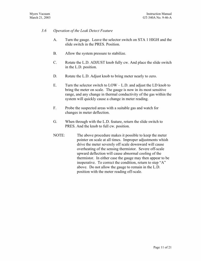
3.6 Operation of the Leak Detect Feature
A. Turn the gauge. Leave the selector switch on STA 1 HIGH and theslide switch in the PRES. Position.
B. Allow the system pressure to stabilize.
C. Rotate the L.D. ADJUST knob fully cw. And place the slide switchin the L.D. position.
D. Rotate the L.D. Adjust knob to bring meter nearly to zero.
E. Turn the selector switch to LOW – L.D. and adjust the LD knob tobring the meter on scale. The gauge is now in its most sensitiverange, and any change in thermal conductivity of the gas within thesystem will quickly cause a change in meter reading.
F. Probe the suspected areas with a suitable gas and watch forchanges in meter deflection.
G. When through with the L.D. feature, return the slide switch toPRES. And the knob to full cw. position.
NOTE: The above procedure makes it possible to keep the meterpointer on scale at all times. Improper adjustments whishdrive the meter severely off scale downward will causeoverheating of the sensing thermistor. Severe off-scaleupward deflection will cause abnormal cooling of thethermistor. In either case the gauge may then appear to beinoperative. To correct the condition, return to step “A”above. Do not allow the gauge to remain in the L.D.position with the meter reading off-scale.

Myers Vacuum Instruction ManualMarch 21, 2003 GT-340A No. 9-46-A
Page 12 of 21
4.0 MAINTENANCE
4.1 Cleaning The Sensing Tube
1. Disconnect and remove the tube from the vacuum system.
2. Wash the tube interior with a hot water and detergent solution (Joyand Alconox are good). Agitate gently.
3. Rinse thoroughly with hot water.
4. Rinse with clean acetone or isopropyl alcohol.
5. Dry tube by heating moderately for several hours and/or byevacuating on a water aspirator. Do not use compressed air.
4.2 Re-calibration
The GT-340A and GT-345A Gauges are carefully calibrated at the factorybefore shipment. Each GT-034 Sensing Tube is also pre-calibrated so thatit can be plugged into a gauge circuit and used without the need for furtheradjustment.
Drift in the calibration or zero setting of the gauge reading is usually dueto contamination of the sensing tube by oil vapor or process contaminants.Cleaning as specified in Section 4.1 will frequently restore the originalaccuracy. Should this fail, instillation of a new GT-034A Tube isrecommended.
4.2.1 Sensing Tube Re-calibration
In cases where, after cleaning the sensing tube, a minor error inpressure or zero reading remains, the tube calibration can beadjusted as follows:
1. Install the sensing tube in the vacuum system and pumpdown to less than 1 millitorr
2. Provide temporary connections from the tube cable socket,contact 1 and 3, to respective pins on the sensing tube.This temporary connection should be made in such a waythat the
Myers Vacuum Instruction ManualMarch 21, 2003 GT-340A No. 9-46-A
Page 13 of 21
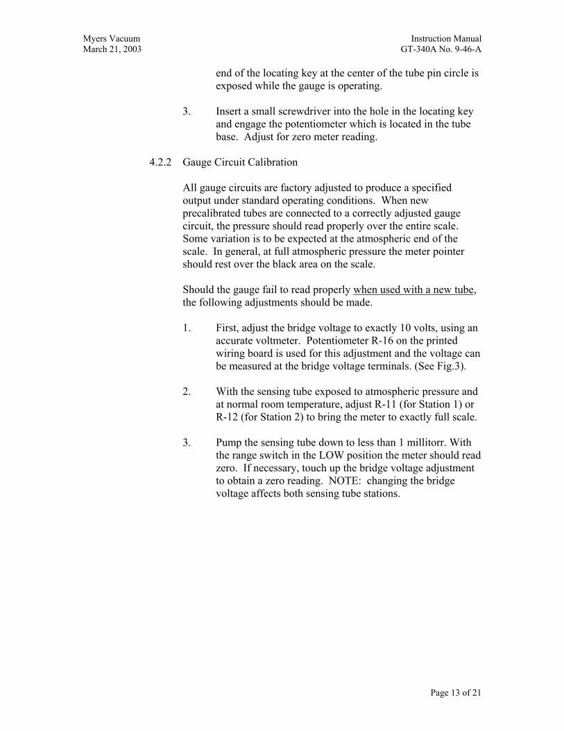
end of the locating key at the center of the tube pin circle isexposed while the gauge is operating.
3. Insert a small screwdriver into the hole in the locating keyand engage the potentiometer which is located in the tubebase. Adjust for zero meter reading.
4.2.2 Gauge Circuit Calibration
All gauge circuits are factory adjusted to produce a specifiedoutput under standard operating conditions. When newprecalibrated tubes are connected to a correctly adjusted gaugecircuit, the pressure should read properly over the entire scale.Some variation is to be expected at the atmospheric end of thescale. In general, at full atmospheric pressure the meter pointershould rest over the black area on the scale.
Should the gauge fail to read properly when used with a new tube,the following adjustments should be made.
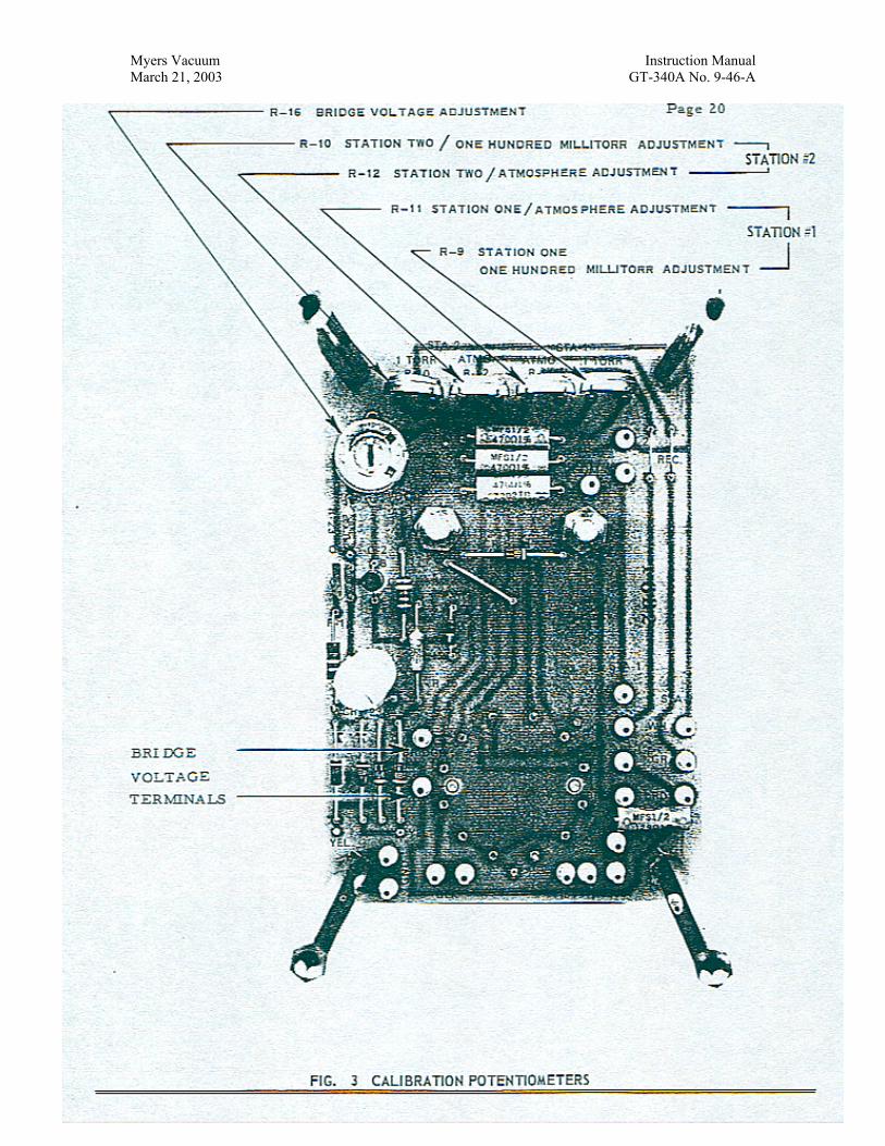
1. First, adjust the bridge voltage to exactly 10 volts, using anaccurate voltmeter. Potentiometer R-16 on the printedwiring board is used for this adjustment and the voltage canbe measured at the bridge voltage terminals. (See Fig.3).
2. With the sensing tube exposed to atmospheric pressure andat normal room temperature, adjust R-11 (for Station 1) orR-12 (for Station 2) to bring the meter to exactly full scale.
3. Pump the sensing tube down to less than 1 millitorr. Withthe range switch in the LOW position the meter should readzero. If necessary, touch up the bridge voltage adjustmentto obtain a zero reading. NOTE: changing the bridgevoltage affects both sensing tube stations.

Myers Vacuum Instruction ManualMarch 21, 2003 GT-340A No. 9-46-A
Page 14 of 21
4. Recheck the atmospheric full scale reading (step 2) and thezero reading (step 3) as there is a slight interaction betweenthese adjustments.
5. The 100-millitorr full scale reading on the LOW scaleprobably will not require adjustment. However, if it is feltto be inaccurate and a gauge of known accuracy isavailable, correction can be made by adjustingpotentiometer R-9 (for Sta. 1) or R-10 (for Sta. 2).
Gauge repair and re-calibration service is available at the factory.For information, contact for local MYERS VACUUM sales officeor the MYERS VACUUM Order Service Dept. Myers Vacuum,Kittanning, Pa 16201.

Myers Vacuum Instruction ManualMarch 21, 2003 GT-340A No. 9-46-A
Page 15 of 21
5.0 REPLACEMENT PARTS LIST FOR THE GT-340A AND GT-345A THERMISTOR TYPE VACUUM GAUGES
MINIMUM ORDER BILLING OF $40.00 PER ORDER. PLEASE INCLUDE PARTNNUMBER AND DESCRIPTION OF EACH PART ORDERED.
DESCRITPION PART NO.
Sensing Tube, Type GT-034 277289Control Unit, Type Gt-005A 5506611
6.0 ACCESSORIES
Cable Assemble for Sensing Tube
Station 1 Station 210 ft. length 5505863-1 5505889-115 ft. length 5505863-2 5505889-225 ft. length 5505869-9 5505889-350 ft. length 5505863-4 5505889-4100 ft. length 5505863-5 5505889-5
Panel Mounting Kit, Type PK-002 277243
Vacuum Grease, Celvacene Medium, 4 oz. 269352-11
Leak Sealant, Celvaseal Silicone, Brush Bottle 271375
Leak Sealant, Celvaseal Silicone, Spray Can 271373
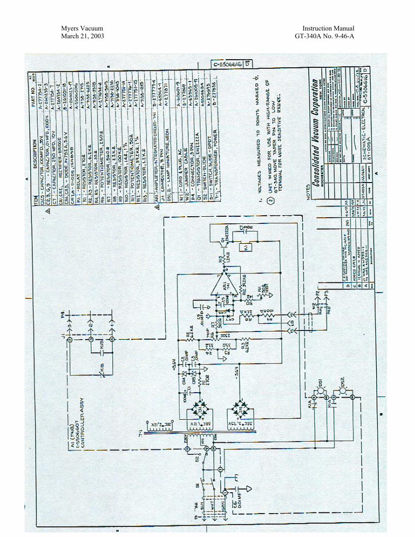
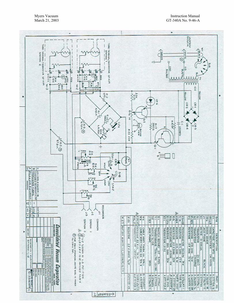
7.0 SCHEMATIC
This section contains the following Electrical Schematics:
7.1 GT-340A C-55063297.2 GT-005A C-5506616
Myers Vacuum Instruction ManualMarch 21, 2003 GT-340A No. 9-46-A
Page 16 of 21
Myers Vacuum Instruction ManualMarch 21, 2003 GT-340A No. 9-46-A
Page 17 of 21
Myers Vacuum Instruction ManualMarch 21, 2003 GT-340A No. 9-46-A
Page 18 of 21
Myers Vacuum Instruction ManualMarch 21, 2003 GT-340A No. 9-46-A
Page 19 of 21
Myers Vacuum Instruction ManualMarch 21, 2003 GT-340A No. 9-46-A
Page 20 of 21

Myers Vacuum Instruction ManualMarch 21, 2003 GT-340A No. 9-46-A
Page 21 of 21


