122
4303-0143 ESE03504-EN9 2020-10 Original manual Instruction Manual Alfa Laval Agitator - ALT / ALTB

4303
-014
3
ESE03504-EN9 2020-10
Original manual
Instruction ManualAlfa Laval Agitator - ALT / ALTB


Table of contents
The information herein is correct at the time of issue but may be subject to change without prior notice
1. EC Declaration of Conformity .. . . . . . . . . . . . . . . . . . . . . . . . . . . . . . . . . . . . . . . . . . . . . . . . . . . . . . . . . . . . . . . . . . . . . . 5
2. Safety .. . . . . . . . . . . . . . . . . . . . . . . . . . . . . . . . . . . . . . . . . . . . . . . . . . . . . . . . . . . . . . . . . . . . . . . . . . . . . . . . . . . . . . . . . . . . . . . . . . . 62.1. Important information ... . . . . . . . . . . . . . . . . . . . . . . . . . . . . . . . . . . . . . . . . . . . . . . . . . . . . . . . . . . . . . . . . . . . . . . . . . . 62.2. Warning signs ... . . . . . . . . . . . . . . . . . . . . . . . . . . . . . . . . . . . . . . . . . . . . . . . . . . . . . . . . . . . . . . . . . . . . . . . . . . . . . . . . . . 62.3. Intended use .. . . . . . . . . . . . . . . . . . . . . . . . . . . . . . . . . . . . . . . . . . . . . . . . . . . . . . . . . . . . . . . . . . . . . . . . . . . . . . . . . . . . . 62.4. Safety precautions ... . . . . . . . . . . . . . . . . . . . . . . . . . . . . . . . . . . . . . . . . . . . . . . . . . . . . . . . . . . . . . . . . . . . . . . . . . . . . . 7
3. Installation .. . . . . . . . . . . . . . . . . . . . . . . . . . . . . . . . . . . . . . . . . . . . . . . . . . . . . . . . . . . . . . . . . . . . . . . . . . . . . . . . . . . . . . . . . . . . . 83.1. Unpacking/delivery .. . . . . . . . . . . . . . . . . . . . . . . . . . . . . . . . . . . . . . . . . . . . . . . . . . . . . . . . . . . . . . . . . . . . . . . . . . . . . . 83.2. Installation .. . . . . . . . . . . . . . . . . . . . . . . . . . . . . . . . . . . . . . . . . . . . . . . . . . . . . . . . . . . . . . . . . . . . . . . . . . . . . . . . . . . . . . . . 113.3. Pre-use check ... . . . . . . . . . . . . . . . . . . . . . . . . . . . . . . . . . . . . . . . . . . . . . . . . . . . . . . . . . . . . . . . . . . . . . . . . . . . . . . . . . . 223.4. Recycling information ... . . . . . . . . . . . . . . . . . . . . . . . . . . . . . . . . . . . . . . . . . . . . . . . . . . . . . . . . . . . . . . . . . . . . . . . . . . 24
4. Operation .. . . . . . . . . . . . . . . . . . . . . . . . . . . . . . . . . . . . . . . . . . . . . . . . . . . . . . . . . . . . . . . . . . . . . . . . . . . . . . . . . . . . . . . . . . . . . . 254.1. Operation/Control . . . . . . . . . . . . . . . . . . . . . . . . . . . . . . . . . . . . . . . . . . . . . . . . . . . . . . . . . . . . . . . . . . . . . . . . . . . . . . . . . 254.2. Troubleshooting .. . . . . . . . . . . . . . . . . . . . . . . . . . . . . . . . . . . . . . . . . . . . . . . . . . . . . . . . . . . . . . . . . . . . . . . . . . . . . . . . . . 264.3. Cleaning - recommendations .. . . . . . . . . . . . . . . . . . . . . . . . . . . . . . . . . . . . . . . . . . . . . . . . . . . . . . . . . . . . . . . . . . . 274.4. Temperature limits . .. . . . . . . . . . . . . . . . . . . . . . . . . . . . . . . . . . . . . . . . . . . . . . . . . . . . . . . . . . . . . . . . . . . . . . . . . . . . . . 274.5. Pressure limits . .. . . . . . . . . . . . . . . . . . . . . . . . . . . . . . . . . . . . . . . . . . . . . . . . . . . . . . . . . . . . . . . . . . . . . . . . . . . . . . . . . . . 28
5. Maintenance ... . . . . . . . . . . . . . . . . . . . . . . . . . . . . . . . . . . . . . . . . . . . . . . . . . . . . . . . . . . . . . . . . . . . . . . . . . . . . . . . . . . . . . . . . 295.1. General Maintenance ... . . . . . . . . . . . . . . . . . . . . . . . . . . . . . . . . . . . . . . . . . . . . . . . . . . . . . . . . . . . . . . . . . . . . . . . . . . 295.2. Replacement of drive unit with bearing frame ... . . . . . . . . . . . . . . . . . . . . . . . . . . . . . . . . . . . . . . . . . . . . . . 305.3. Replacement of drive unit . . . . . . . . . . . . . . . . . . . . . . . . . . . . . . . . . . . . . . . . . . . . . . . . . . . . . . . . . . . . . . . . . . . . . . . . 325.4. Replacement of drive unit (Motor and shaft unit) . . . . . . . . . . . . . . . . . . . . . . . . . . . . . . . . . . . . . . . . . . . . . . 345.5. Dismantling and mounting shaft (with bearing frame except BC160) . . . . . . . . . . . . . . . . . . . . . . . 355.6. Replacement of bearings, type B20, B25, B25/30, B35, B35/40, B45, B45/50, B55,
B55/60 ... . . . . . . . . . . . . . . . . . . . . . . . . . . . . . . . . . . . . . . . . . . . . . . . . . . . . . . . . . . . . . . . . . . . . . . . . . . . . . . . . . . . . . . . . . . 375.7. Replacement of bearings, type BC160DH ... . . . . . . . . . . . . . . . . . . . . . . . . . . . . . . . . . . . . . . . . . . . . . . . . . . 395.8. Replacement of bearing, type BC160D .... . . . . . . . . . . . . . . . . . . . . . . . . . . . . . . . . . . . . . . . . . . . . . . . . . . . . 415.9. Replacement of bearings type BC160 ... . . . . . . . . . . . . . . . . . . . . . . . . . . . . . . . . . . . . . . . . . . . . . . . . . . . . . . . 435.10.Replacement of shaft seal, type D .... . . . . . . . . . . . . . . . . . . . . . . . . . . . . . . . . . . . . . . . . . . . . . . . . . . . . . . . . . . 455.11.Replacement of shaft seal, type DC ... . . . . . . . . . . . . . . . . . . . . . . . . . . . . . . . . . . . . . . . . . . . . . . . . . . . . . . . . . 485.12.Replacement of shaft seal, type S (and type S with dust trap) . . . . . . . . . . . . . . . . . . . . . . . . . . . . . . . 515.13.Replacement of shaft seal, type S3 ... . . . . . . . . . . . . . . . . . . . . . . . . . . . . . . . . . . . . . . . . . . . . . . . . . . . . . . . . . . 555.14.Replacement of shaft seal, type R or G .... . . . . . . . . . . . . . . . . . . . . . . . . . . . . . . . . . . . . . . . . . . . . . . . . . . . . 585.15.Replacement of shaft seal, type V .. .. . . . . . . . . . . . . . . . . . . . . . . . . . . . . . . . . . . . . . . . . . . . . . . . . . . . . . . . . . . 615.16.Replacement of wear bushing in intermediate bearing support .. . . . . . . . . . . . . . . . . . . . . . . . . . . . . 635.17.Replacement of wear bushing in bottom support . . . . . . . . . . . . . . . . . . . . . . . . . . . . . . . . . . . . . . . . . . . . . 64
6. Technical Data .. . . . . . . . . . . . . . . . . . . . . . . . . . . . . . . . . . . . . . . . . . . . . . . . . . . . . . . . . . . . . . . . . . . . . . . . . . . . . . . . . . . . . . . . 656.1. Technical data ... . . . . . . . . . . . . . . . . . . . . . . . . . . . . . . . . . . . . . . . . . . . . . . . . . . . . . . . . . . . . . . . . . . . . . . . . . . . . . . . . . . 656.2. Mounting angle for top mounting agitator type ALT .... . . . . . . . . . . . . . . . . . . . . . . . . . . . . . . . . . . . . . . . 666.3. Mounting angle for top mounting agitator type ALTB ... . . . . . . . . . . . . . . . . . . . . . . . . . . . . . . . . . . . . . . 686.4. Connecting flush – Seal type D ... . . . . . . . . . . . . . . . . . . . . . . . . . . . . . . . . . . . . . . . . . . . . . . . . . . . . . . . . . . . . . . . 696.5. Connecting flush – Seal type DC .... . . . . . . . . . . . . . . . . . . . . . . . . . . . . . . . . . . . . . . . . . . . . . . . . . . . . . . . . . . . . 716.6. Tightening torques for bolt connections .. . . . . . . . . . . . . . . . . . . . . . . . . . . . . . . . . . . . . . . . . . . . . . . . . . . . . . . 736.7. Shaft alignment .. . . . . . . . . . . . . . . . . . . . . . . . . . . . . . . . . . . . . . . . . . . . . . . . . . . . . . . . . . . . . . . . . . . . . . . . . . . . . . . . . . 746.8. Spider coupling .. . . . . . . . . . . . . . . . . . . . . . . . . . . . . . . . . . . . . . . . . . . . . . . . . . . . . . . . . . . . . . . . . . . . . . . . . . . . . . . . . . 766.9. Bottom support alignment .. . . . . . . . . . . . . . . . . . . . . . . . . . . . . . . . . . . . . . . . . . . . . . . . . . . . . . . . . . . . . . . . . . . . . . 776.10.Bottom support positioning .. . . . . . . . . . . . . . . . . . . . . . . . . . . . . . . . . . . . . . . . . . . . . . . . . . . . . . . . . . . . . . . . . . . . . 78
3

Table of contents
The information herein is correct at the time of issue but may be subject to change without prior notice
6.11.Storage ... . . . . . . . . . . . . . . . . . . . . . . . . . . . . . . . . . . . . . . . . . . . . . . . . . . . . . . . . . . . . . . . . . . . . . . . . . . . . . . . . . . . . . . . . . 79
7. Part lists, part drawings and service kits .. . . . . . . . . . . . . . . . . . . . . . . . . . . . . . . . . . . . . . . . . . . . . . . . . . . . . . . . 807.1. Agitator Main Components, Drive end .. . . . . . . . . . . . . . . . . . . . . . . . . . . . . . . . . . . . . . . . . . . . . . . . . . . . . . . . . 807.2. Agitator Main Components, Wet end ... . . . . . . . . . . . . . . . . . . . . . . . . . . . . . . . . . . . . . . . . . . . . . . . . . . . . . . . . 827.3. Bearing frame, B20, B25, B25/30, B35, B35/40, B45, B45/50, B55, B55/60 ... . . . . . . . . . . 847.4. Bearing frame BC160/35, BC160D/30, BC160DH/30 .. . . . . . . . . . . . . . . . . . . . . . . . . . . . . . . . . . . . . . 887.5. Shaft seal, type S ... . . . . . . . . . . . . . . . . . . . . . . . . . . . . . . . . . . . . . . . . . . . . . . . . . . . . . . . . . . . . . . . . . . . . . . . . . . . . . . 907.6. Shaft seal, type S with dust trap ... . . . . . . . . . . . . . . . . . . . . . . . . . . . . . . . . . . . . . . . . . . . . . . . . . . . . . . . . . . . . . 927.7. Shaft seal, type S3 ... . . . . . . . . . . . . . . . . . . . . . . . . . . . . . . . . . . . . . . . . . . . . . . . . . . . . . . . . . . . . . . . . . . . . . . . . . . . . . 947.8. Shaft seal, type D ... . . . . . . . . . . . . . . . . . . . . . . . . . . . . . . . . . . . . . . . . . . . . . . . . . . . . . . . . . . . . . . . . . . . . . . . . . . . . . . 987.9. Shaft seal, type DC .... . . . . . . . . . . . . . . . . . . . . . . . . . . . . . . . . . . . . . . . . . . . . . . . . . . . . . . . . . . . . . . . . . . . . . . . . . . . 1007.10.Shaft seal, type R ... . . . . . . . . . . . . . . . . . . . . . . . . . . . . . . . . . . . . . . . . . . . . . . . . . . . . . . . . . . . . . . . . . . . . . . . . . . . . . . 1047.11.Shaft seal, type G ... . . . . . . . . . . . . . . . . . . . . . . . . . . . . . . . . . . . . . . . . . . . . . . . . . . . . . . . . . . . . . . . . . . . . . . . . . . . . . . 1087.12.Shaft seal, type V ... . . . . . . . . . . . . . . . . . . . . . . . . . . . . . . . . . . . . . . . . . . . . . . . . . . . . . . . . . . . . . . . . . . . . . . . . . . . . . . 1127.13. Intermediate support .. . . . . . . . . . . . . . . . . . . . . . . . . . . . . . . . . . . . . . . . . . . . . . . . . . . . . . . . . . . . . . . . . . . . . . . . . . . . 1147.14.Bottom support, type 3 .. . . . . . . . . . . . . . . . . . . . . . . . . . . . . . . . . . . . . . . . . . . . . . . . . . . . . . . . . . . . . . . . . . . . . . . . . 1167.15.Tools .. . . . . . . . . . . . . . . . . . . . . . . . . . . . . . . . . . . . . . . . . . . . . . . . . . . . . . . . . . . . . . . . . . . . . . . . . . . . . . . . . . . . . . . . . . . . . . 118
8. Appendix .. . . . . . . . . . . . . . . . . . . . . . . . . . . . . . . . . . . . . . . . . . . . . . . . . . . . . . . . . . . . . . . . . . . . . . . . . . . . . . . . . . . . . . . . . . . . . . 1208.1. Drive unit instructions .. . . . . . . . . . . . . . . . . . . . . . . . . . . . . . . . . . . . . . . . . . . . . . . . . . . . . . . . . . . . . . . . . . . . . . . . . . . . 120
4

1 EC Declaration of Conformity
Revision of Declaration of Conformity: 2018-02-01
The Designated Company
Alfa Laval Kolding A/SCompany Name
Albuen 31, DK-6000 Kolding, DenmarkAddress
+45 79 32 22 00Phone No.
hereby declare that
Agitator - EnSaFoil / EnSaFerm
Serial number from AAC000000001 to AAC999999999
Serial number from 10.000 to 100.000
Serial number from 100700000001 to 100799999999Designation Serial no(s)
GX = GC, GR or GPBXX/XX = B20, B25, B25/30, B35, B35/40,
B45, B45/50, B55, B55/60ALT(B)-ME-(GX)-BC160D(H)/30(L)F-SX-SH-(n)(PXXXXDYY)(-PXXXXDYLY)(-LXXXXY)(-MSXX)(-BSXX) SX = S, S3ALT(B)-ME-(GX)-BC160/35(L)F-SX-SH-(n)(PXXXXDYY)(-PXXXXDYLY)(-LXXXXY)(-MSXX)(-BSXX) SH = S500-S15000ALT(B)-ME-(GX)-BXX/XX(L)F-SX-SH-(n)(PXXXXDYY)(-PXXXXDYLY)(-LXXXXY)(-MSXX)(-BSXX) PXXXX E125, E150, E175, E200, E225, E250, E300ALT(B)-ME-(GX)-BC160D(H)/30(L)F-D(C)-SH-(n)(PXXXXDYY)(-PXXXXDYLY)(-LXXXXY)(-MSXX)(-BSXX) E350, E400, E450, E500, E550, E600, E650ALT(B)-ME-(GX)-BC160/35(L)F-D(C)-SH-(n)(PXXXXDYY)(-PXXXXDYLY)(-LXXXXY)(-MSXX)(-BSXX) E700, E750, E800, E900, E1000, E1100ALT(B)-ME-(GX)-BXX/XX(L)F-D(C)-SH-(n)(PXXXXDYY)(-PXXXXDYLY)(-LXXXXY)(-MSXX)(-BSXX) E1300, E1500, E1700, E1900ALT(B)-ME-(GX)-BC160D(H)/30(L)F-R-SH-(n)(PXXXXDYY)(-PXXXXDYLY)(-LXXXXY)(-MSXX)(-BSXX) F450, F500, F550, F600, F650, F700, F750,ALT(B)-ME-(GX)-BC160/35(L)F-R-SH-(n)(PXXXXDYY)(-PXXXXDYLY)(-LXXXXY)(-MSXX)(-BSXX) F800, F900, F1000, F1100, F1300, F1500ALT(B)-ME-(GX)-BXX/XX(L)F-R-SH-(n)(PXXXXDYY)(-PXXXXDYLY)(-LXXXXY)(-MSXX)(-BSXX) F1700, F1900ALT(B)-ME-(GX)-BC160D(H)/30(L)F-G-SH-(n)(PXXXXDYY)(-PXXXXDYLY)(-LXXXXY)(-MSXX)(-BSXX) LXXXX = L600, L800, L900, L1100, L1300,ALT(B)-ME-(GX)-BC160/35(L)F-G-SH-(n)(PXXXXDYY)(-PXXXXDYLY)(-LXXXXY)(-MSXX)(-BSXX) L1500, L1700ALT(B)-ME-(GX)-BXX/XX(L)F-G-SH-(n)(PXXXXDYY)(-PXXXXDYLY)(-LXXXXY)(-MSXX)(-BSXX) DY = D2, D3ALT(B)-ME-(GX)-ZZ(L)F-SX-SH-(n)(PXXXXDYY)(-PXXXXDYLY)(-LXXXXY)(-MSXX)(-BSXX) Y = P, GALT(B)-ME-(GX)-ZZ(L)F-D(C)-SH-(n)(PXXXXDYY)(-PXXXXDYLY)(-LXXXXY)(-MSXX)(-BSXX) BSXX BS3P, BS3GALT(B)-ME-(GX)-ZZ(L)F-R-SH-(n)(PXXXXDYY)(-PXXXXDYLY)(-LXXXXY)(-MSXX)(-BSXX) MSXX = MS2P, MS2GALT(B)-ME-(GX)-ZZ(L)F-G-SH-(n)(PXXXXDYY)(-PXXXXDYLY)(-LXXXXY)(-MSXX)(-BSXX) ZZ = 20, 25, 30, 35, 40, 45, 50, 55, 60, 65,ALT-ME-ZZF-V-SH-PXXXXDYY 70, 75, 80, 90
Type Type variation
is in conformity with the following directives:
Machinery Directive 2006/42/EC++Regulation (EC) 1935/2004
The person authorised to compile the technical file is the signer of this document.
Global Product Quality ManagerPumps, Valves, Fittings and Tank Equipment Lars Kruse Andersen
Title Name
Kolding 2020-02-01Place Date (YYYY-MM-DD) Signature
5

2 Safety
Unsafe practices and other important information are emphasised in this manual.Warnings are emphasised by means of special signs.Always read the manual before using the Agitator!Illustrations are only to illustrate the problem and is NOT a drawing of the current Agitator!
2.1 Important information
WARNINGIndicates that special procedures must be followed to avoid serious personal injury.
CAUTIONIndicates that special procedures must be followed to avoid damage to the agitator!
NOTEIndicates important information to simplify or clarify procedures.
2.2 Warning signs
General warning: !
Dangerous electrical voltage:
2.3 Intended use
- The Alfa Laval Agitator is only for mixing/stirring of liquids in a tank.- The Agitator is only for mounting positions as specified on the nameplate by the first group of letters of the type designation.
ALT(B)- is for top mounting, ALS- is for side mounting and ALB- is for bottom mounting.The exact mounting angle is specified on the Name Plate and must be followed. Definitions on mounting angles can be seen insection 6.2 Mounting angle for top mounting agitator type ALT.
- The different duties and operation data like pressure, speed and media temperature, which the Agitator is designed for, canbe found in the Alfa Laval quotation agreement1) and may not be exceeded by all means.
- If the Agitator is installed in pressurized tanks local regulations and legislations must be met.
1) The Alfa Laval quotation agreement has been exchanged during the quote process between a technical purchaser and Alfa Laval. If you arenot in hold of the Alfa Laval quotation agreement, please get through to your local Alfa Laval contact, inform the Agitator serial number andarticle number which is stated on the Name Plate and you will obtain the Alfa Laval quotation agreement.
6

2 Safety
All warnings in the manual are summarised on this page.Pay special attention to the instructions below so that severe personal injury and/or damage to the Agitator are avoided.
2.4 Safety precautions
Installation:Always read the technical data thoroughly (see chapter 6 Technical Data).Always follow installation instructions thoroughly (see chapter 3 Installation).Never expose the Agitator to undue vibrations or shocks.Never start Agitator in the wrong rotation direction.Ensure that the tank media is not corrosive to the Agitator.Only install the Agitator in environments within temperature limit: -20°C and +40°C.Only install the Agitator in altitudes less than 1000 m above sea level.
!
Never touch the moving parts while the Agitator is connected to the power supply.
Operation:Always read the technical data thoroughly (see chapter 6 Technical Data).Always read supplier instructions thoroughly (see chapter 8 Appendix).Never start Agitator in the wrong rotation direction.Always rinse well with clean water after cleaning.Beware of temperature limitations.Beware of Agitator in operation can produce sound levels in excess of 85dB(A).Never operate continuously within 20% of critical oscillation speed (see chapter 6 Technical Data).
!
Never touch the moving parts while the Agitator is connected to the power supply.
Maintenance:Always read the technical data thoroughly (see chapter 6 Technical Data).Always follow the maintenance instruction thoroughly (see chapter 5 Maintenance).Always follow the maintenance instruction from drive unit supplier (see chapter 8 Appendix).Always study the parts list and assembly drawing carefully (see chapter 7 Part lists, part drawings and service kits).
!
Never touch the moving parts while the Agitator is connected to the power supply.Always disconnect the power supply while servicing the Agitator.
Ensure correct rotation direction of impeller before startup and after any maintains there might have impact on thedirection.
Transportation:Always transport the Agitator in original packaging.Always support the shaft adequately, to protect shaft and bearings.Never expose the Agitator to undue vibrations or shocks.Control for oil leakage on gears with vent screw.
7

3 Installation
The instructions manual is part of the delivery.Study the instructions carefully.
3.1 Unpacking/delivery
Always use lifting equipment when handling the Agitator (see step 3).
CAUTION
Alfa Laval cannot be held responsible for incorrect unpacking.
Step 1
Inspect the delivery for visible transportation damages - all issues to be reported to carrier.
Step 2Check the delivery for:1. Complete Agitator2. Nameplate designations3. Delivery note4. Separate instruction manuals from suppliers (see chapter 8 Appendix).
4303
-000
6
Step 3Lifting instructions:
Always use the correct lifting equipment (see Agitator weight on name plate).Locate Centre of gravity before moving the Agitator.
4303-0051
8

3 Installation
The instructions manual is part of the delivery.Study the instructions carefully.
TD605-103
WARNINGDo NOT use eye bolts on gear motor to lift the Agitator. They are only for gear motor removal.
TD605-101
WARNINGDo NOT use eye bolts on shroud (if any) to lift the Agitator.They are only for shroud removal.
4303
-005
2
9

3 Installation
The instructions manual is part of the delivery.Study the instructions carefully.
CAUTIONAlfa Laval recommends NOT to use shaft as lifting point but long shafts must be supported adequately during lifting to protectshaft, bearings and seals arrangements.Gear motor / motor may be used for lifting the assembled agitator.
NOTEIf possible, lift the Agitator in horizontal position, and in two points.
Step 4During transportation
1. Always support the shaft adequately, to protect shaft and bearings.2. Never expose the Agitator to undue vibrations or shocks.3. Control for oil leakage on gears with vent screw.
10

3 Installation
Study the instructions carefully and pay special attention to the warnings!Always check the Agitator before operation - see section 3.3 Pre-use check.The Agitator is for permanent fastening.Make sure that the motor correspond to the environment.
3.2 Installation
Always read the technical data thoroughly (see chapter 6 Technical Data).Only install this Agitator in mounting angle according to the name plate (see chapter 6 Technical Data).Always use lifting equipment when handling the Agitator (see Step 2).Always have safety elements removed by authorized personnel.Never cover or remove the nameplate.
Never connect to power supply during installation or service.Always have the Agitator connected to power supply by authorized personnel.
NOTEAlfa Laval highly recommend to install motor protection guard to protect the motor from overloading.Never install a none Alfa Laval shroud on the agitator as it can lead to overheat and a breakdown of the motor.
Alfa Laval highly recommends to use shaft retainer tool for installation of Agitator within a weight less than 500 kilogram and ashaft diameter between Ø30 and Ø60 (see section 7.15 Tools).
Welding flange - Flat Shaped Welding Flange (FSWF):
CAUTIONOnly authorized personnel to weld in flanges.Alfa Laval cannot be held responsible for incorrect installation.
TD60
5-09
6
Step 1Dismantle the FSWF if fitted onto the Agitator.
2
1
TD605-004
11

3 Installation
Study the instructions carefully and pay special attention to the warnings!Always check the Agitator before operation - see section 3.3 Pre-use check.The Agitator is for permanent fastening.Make sure that the motor correspond to the environment.
Step 2Ensure that the tank, where the welding flange are to be welded in,can handle the forces applied by the agitator: Torque Mv, Bendingtorque Mb and Side thrust Fs.
The values are depending on the Agitator configuration. Thefollowing information is required to calculate the forces:
P: Power of the motor in [kW]n: Speed of Agitator shaft [RPM]S: Shaft length according to Agitator type designation -Sxxxx-in [mm]D: Largest impeller diameter according to Agitator designation-Pxxx- in [mm]
The values can be calculated as follows:
Type ALT / ALTB:Mv [Nm] = 23873 x P / nFs [N] = 4.5 x Mv x 1000 / D
Type ALT:Mb [Nm] = Fs x S / 1000
Type ALTB:Mb [Nm] = Fs x S / 5333
TD605-028
Mv
Mb
FsFs
Mb
Step 3During the design phase of the tank, ensure sufficiently rigidityof the tank.Ensure that the max. bending angle (A), at loads from Step 2 doesnot exceed according to below scheme
RPM: <100 >100
A° (max bending angle at applied loads): 0.1 0.05
A
TD60
5-21
3Mb
FsFs
Mb
12
3 Installation
Study the instructions carefully and pay special attention to the warnings!Always check the Agitator before operation - see section 3.3 Pre-use check.The Agitator is for permanent fastening.Make sure that the motor correspond to the environment.
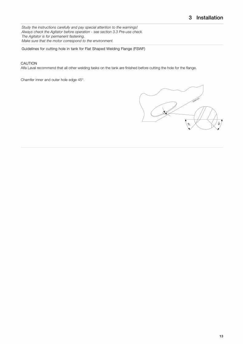
Guidelines for cutting hole in tank for Flat Shaped Welding Flange (FSWF)
CAUTIONAlfa Laval recommend that all other welding tasks on the tank are finished before cutting the hole for the flange.
Chamfer inner and outer hole edge 45°.
45°45°
TD605-023
13

3 Installation
Study the instructions carefully and pay special attention to the warnings!Always check the Agitator before operation - see section 3.3 Pre-use check.The Agitator is for permanent fastening.Make sure that the motor correspond to the environment.
Welding procedure, flange (FSWF) without nose:
Step 1Always allow flange to cool to ambient temperature after each section has been weldedPosition the flange correctly
TD605-006
A
B
C
D
TD605-007
Step 2Spot weld from outside.
TD605-010
A
C
D B Adjust alignment!
A
C
D BTD605-011
Step 3
Weld the following sections first from outside then from inside, and coolwith air between each section.
1
A
B
C
D
42
3
TD605-014
Step 4
Ensure that the surface flatness tolerance equals 0,25 after welding.Grind and polish the welding flange.Use a solid straight ruler and a feeler gauge to determine the flatness.
4303
-002
2
14

3 Installation
Study the instructions carefully and pay special attention to the warnings!Always check the Agitator before operation - see section 3.3 Pre-use check.The Agitator is for permanent fastening.Make sure that the motor correspond to the environment.
Welding procedure, flange (FSWF) with nose:
NOTEAlfa Laval recommend a welding tool with, if possible, build in cooling by flowing water, to be made and fixed to the FSWF toensure shape and form of the FSWF during welding and installation.In general Alfa Laval recommend to weld the welding flange onto a bended rim of the tank bottom plate – this is to secureadequate flexibility at high loads, e.g. when the tank is filled. If a bended rim is impossible to obtain due to a high platethickness, Alfa Laval recommend to weld the welding flange onto a cone shaped plate section.If not following the above recommendations there will be a risk that the flange can deform, especially at high tank fillings, whichcan cause a leakage between the welding flange and the agitator mounting flange.
Step 1Position the flange correctly.Always allow flange to cool to ambient temperature after each section has been welded.
Step 2Spot weld from outside.
TD605-214
A
C
Adjust alignment! TD605-215BD
Step 3
Spot weld from inside
TD605-216
5
12
7
1
11
3
10
2
6
4
8
9
15

3 Installation
Study the instructions carefully and pay special attention to the warnings!Always check the Agitator before operation - see section 3.3 Pre-use check.The Agitator is for permanent fastening.Make sure that the motor correspond to the environment.
Step 4Weld the following sections first from inside then from outside and cool to ambient temperature after each section has beenwelded
Step 1 Step 2 Step 3
TD605-217
A
B
C
D
E
FG
H
1
2
3
TD605-218
4
5
A
B
C
D
E
FG
H
TD605-219
A
B
C
D
E
FG
H
8
67
Cool with air! Cool with air! Cool with air!
Step 5Remove the welding tool.Ensure that the surface flatness tolerance equals ±0.1mm.Grind and polish the welding flange.
16

3 Installation
Study the instructions carefully and pay special attention to the warnings!Always check the Agitator before operation - see section 3.3 Pre-use check.The Agitator is for permanent fastening.Make sure that the motor correspond to the environment.
Welding procedure for divided shaft with thread connection:
NOTEOnly relevant for divided shafts prepared for welding.
Step 1Ensure that shaft ends are screwed completely together.
Step 2Spot weld and cool with air.
Step 3All-weld shaft connections with one welding seam at a time, coolwith air and continue with one welding until welding is accordingto illustration. Use welding procedures which introduce as lesstension and bending to the shaft as possible.
Step 4If shaft sleeve is used weld as described in step 3.
Step 5Align the shaft, using heat and or bending forces according to specifications in section 6.7 Shaft alignment.
17

3 Installation
Study the instructions carefully and pay special attention to the warnings!Always check the Agitator before operation - see section 3.3 Pre-use check.The Agitator is for permanent fastening.Make sure that the motor correspond to the environment.
Mounting Agitator:CAUTIONAlways ensure that mounting is carried out according to description shown in section 6.2 Mounting angle for top mountingagitator type ALT and 6.3 Mounting angle for top mounting agitator type ALTB.Always refer to tightening torques in section 6.6 Tightening torques for bolt connections when tightening bolts.
Step 1Place impeller device(s) in the tank.Ensure that tank and Agitator surfaces are clean.Ensure that drain (I) is pointing downwards.For gears with vent screw, ensure the vent is pointing upwards and the rubber plug (III) is removed (see section 8.1 Drive unitinstructions).
III
I
4303-0053
1) Standard vent plug2) Transport securing device
Step 2Mount the Agitator onto the tank.
NOTEAlfa Laval recommends using shaft retainer tool during mounting and dismantling (see section 7.15 Tools).
Step 3(Only for ALTB machines with Intermediate steady bearing)- Mount the intermediate steady bearing onto the shaft.- Ensure before welding that the intermediate steady bearing is
perpendicular to the mounting flange.- Position wear bushings according to shaft diameter.
TD605-137
18

3 Installation
Study the instructions carefully and pay special attention to the warnings!Always check the Agitator before operation - see section 3.3 Pre-use check.The Agitator is for permanent fastening.Make sure that the motor correspond to the environment.
Step 4Mount impeller device(s) onto shaft.
Hub diameter [mm] a - dimension [mm]Ø30 1,1Ø40 1,8Ø55, Ø80, Ø120 2,8
TD605-037
3 x
3 x
TD605-038
aa
All-weld propeller to shaft with one welding seam ata time, cool with air and continue with one weldinguntil welding is according to illustration. Use weldingprocedures which introduce as less heat, tensionand bending to the shaft as possible.
TD605-035
x 4 x 1
TD605-036
TD605-031
TD605-032
TD605-033 TD605-034
Step 5Ensure the impeller device orientation is correct according to the direction of the desired flow. The direction is determined by theletter "D" or "U" in the last part of the agitator type description. E.g. -P400D3P has the letter "D" which means the flow directionis away from the drive unit. -P400U3P has the letter "U" which means the flow direction is towards the drive unit.
19

3 Installation
Study the instructions carefully and pay special attention to the warnings!Always check the Agitator before operation - see section 3.3 Pre-use check.The Agitator is for permanent fastening.Make sure that the motor correspond to the environment.
Step 6
Ensure the impeller is positioned, keeping minimum radialdistance to the tank.
Further installation requirements regarding the position canbe found in 6.2 Mounting angle for top mounting agitatortype ALT and 6.3 Mounting angle for top mounting agitatortype ALTB to ensure optimum performance.
Clearance > S/15xsin(V)
NOTEIn special cases clearance can be reduce to 20mm+actualdeflection, please advice with Alfa Laval.
S
15
TD605-026
S> __
V
Clearence
Step 7(Only when shaft is divided)Assemble all shaft parts as shown on the figure.
Step 8Align the shaft, using heat and or bending forces according tospecifications and instructions in section 6.7 Shaft alignment.
20

3 Installation
Study the instructions carefully and pay special attention to the warnings!Always check the Agitator before operation - see section 3.3 Pre-use check.The Agitator is for permanent fastening.Make sure that the motor correspond to the environment.
Step 9(Only for ALTB machines)
- Adjust legs according to tank bottom shape and position thebottom support in angle (V) according to horizontal of 12°+/- 1.5° as illustrated.
CAUTIONIf the angle is not respected an increased risk for vibration canoccur.
4303-0162
>XX
X1
X1
V
WARNINGDo NOT connect the power supply until installation is completed.
CAUTIONFollow instructions in section 8.1 Drive unit instructionsEnsure that the rotation direction is according to nameplate.Always perform pre-use check before operation (see section 3.3 Pre-use check).
NOTEOn closed tanks, Alfa Laval recommends installing a manhole circuit breaker, cutting power supply if hatch is open.
21

3 Installation
Study the instructions carefully and pay special attention to the warnings! Always check the Agitator before operation. TheAgitator is only designed to operate according to data given in section 2.3 Intended use, 6.2 Mounting angle for top mountingagitator type ALT and 6.3 Mounting angle for top mounting agitator type ALTB. Check the rotation direction before operation.
3.3 Pre-use check
Never install the Agitator in environments which deviate from those given in section 2.3 Intended use and 6.1 Technical data.Always ensure that all alignment specifications given in section 6.7 Shaft alignment are followed.Always make sure that the motor corresponds to the environment.
Step 1Go through section 2.4 Safety precautions.
Step 2Check the fastenings.
Step 3Check o-ring and impeller are correctly fitted.
Step 4Check impellers CANNOT collide with tank vessel at any pointduring a full rotation.Clearance > S/15*sin(V)
NOTEIn special cases clearance can be reduced to 20mm+actualdeflection, please advise with Alfa Laval.
S15
TD605-026
S> __
V
Clearence
Step 5Seal Type DEnsure the sealing surfaces are not stuck together, by slowly turning shaft by hand.Ensure that the seal never runs dry.Ensure flush connections are installed in such way that air pockets are avoided.
TD605-078
TD605-079
22

3 Installation
Study the instructions carefully and pay special attention to the warnings! Always check the Agitator before operation. TheAgitator is only designed to operate according to data given in section 2.3 Intended use, 6.2 Mounting angle for top mountingagitator type ALT and 6.3 Mounting angle for top mounting agitator type ALTB. Check the rotation direction before operation.
Step 6Seal Type DCEnsure the sealing surfaces are not stuck together, by slowly turning shaft by hand.Ensure that the seal never runs dry.Ensure flush connections are installed in such way that air pockets are avoided.Ensure that the distance pieces (1) on the seal are mounted as shown on illustration.
1
IN
TD605-170
OUT
Step 7Ensure that drain (I) is pointing downwards.For gears with vent screw, ensure the vent is pointing upwards and the rubber plug (III) is removed (see section 8.1 Drive unitinstructions and mounting instructions in Step 1 on page 18.
III
I
4303-0053
Step 8(Only for agitators with bearing frame)Ensure that the PreVent valve is refitted in the bearing frame.
TD605-180
23
3 Installation
Study the instructions carefully and pay special attention to the warnings! Always check the Agitator before operation. TheAgitator is only designed to operate according to data given in section 2.3 Intended use, 6.2 Mounting angle for top mountingagitator type ALT and 6.3 Mounting angle for top mounting agitator type ALTB. Check the rotation direction before operation.
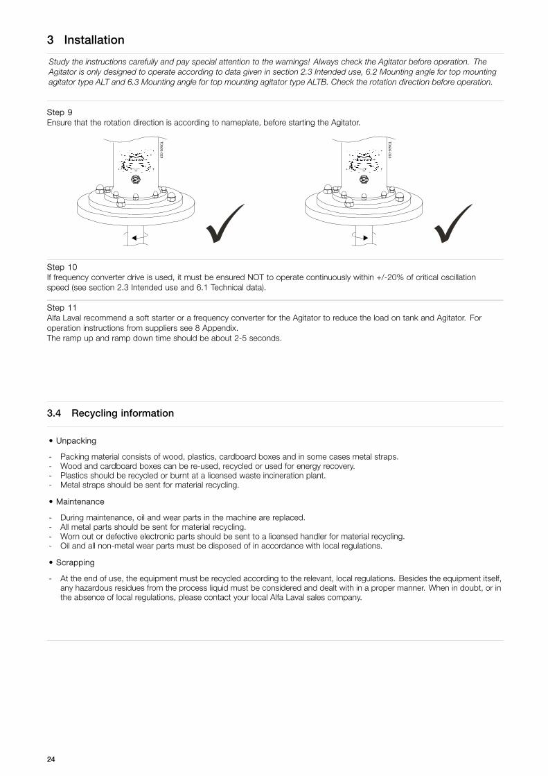
Step 9Ensure that the rotation direction is according to nameplate, before starting the Agitator.
TD605-029
TD605-030
Step 10If frequency converter drive is used, it must be ensured NOT to operate continuously within +/-20% of critical oscillationspeed (see section 2.3 Intended use and 6.1 Technical data).
Step 11Alfa Laval recommend a soft starter or a frequency converter for the Agitator to reduce the load on tank and Agitator. Foroperation instructions from suppliers see 8 Appendix.The ramp up and ramp down time should be about 2-5 seconds.
3.4 Recycling information
• Unpacking
- Packing material consists of wood, plastics, cardboard boxes and in some cases metal straps.- Wood and cardboard boxes can be re-used, recycled or used for energy recovery.- Plastics should be recycled or burnt at a licensed waste incineration plant.- Metal straps should be sent for material recycling.
• Maintenance
- During maintenance, oil and wear parts in the machine are replaced.- All metal parts should be sent for material recycling.- Worn out or defective electronic parts should be sent to a licensed handler for material recycling.- Oil and all non-metal wear parts must be disposed of in accordance with local regulations.
• Scrapping
- At the end of use, the equipment must be recycled according to the relevant, local regulations. Besides the equipment itself,any hazardous residues from the process liquid must be considered and dealt with in a proper manner. When in doubt, or inthe absence of local regulations, please contact your local Alfa Laval sales company.
24

4 Operation
Study the instructions carefully and pay special attention to warnings! Always check the Agitator before operation (seesection 3.3 Pre-use check).Alfa Laval recommend a soft starter or a frequency converter for the Agitator to reduce the load on tank and Agitator. Foroperation instructions from suppliers (see chapter 8 Appendix).
4.1 Operation/Control
If deviation from normal operation and intended use shown in section 2.3 Intended use, immediately switch off the Agitator andfind the cause of failure (see section 4.2 Troubleshooting).The Agitator is designed to max 5 starts per hour.The Agitator is normally constructed for use with the lower impeller adequately submerged in the liquid. However, the Agitatorcan be dimensioned for use while emptying the tank completely (see section 2.3 Intended use).
Inspect the Agitator regularly
Inspect / Clean / LubricateSupplier
instructionWeekly Monthly Half-yearly
Drive unitMotor x- Clean surfaces - to avoid overheating xGear x- Clean vent screw (if any) x- Check for oil leakage xFlangeClean drain xSealingShaft seal- Radial seal: R x- Gab seal: G- V-ring seal: V xMechanical seal- NOT flushed: S, S3 x- Flushed: DC, D xBearing frameClean PreVent screw xCheck spider clearance xCheck gaskets xLubricate radial seals xGuidanceShaft rotation - radial movement < 5mm- Bushing: BS3 x- Bushing: MS2 xImpeller deviceSticky media- Clean impeller device xAbrasive media- Check blade thickness* xCheck fastening of pointed set screws x
* If any suspicion of reduction in blade thickness, contact Alfa Laval and inform serial no stated on the name plate.
25

4 Operation
Study the instructions carefully and pay special attention to warnings! Always check the Agitator before operation (seesection 3.3 Pre-use check).Alfa Laval recommend a soft starter or a frequency converter for the Agitator to reduce the load on tank and Agitator. Foroperation instructions from suppliers (see chapter 8 Appendix).
4.2 Troubleshooting
ProblemNot starting
Cause/result Remedy
- Defect Dismantle drive unit, check for correct rotation. Replace drive unit- Fault at power supply Check power supply connection
Check voltage and frequency correspond with name plate
Drive unit
Check frequency converter adjustment correspond to name plateAgitator - Obstructed Check Agitator can rotate freely without stricking anythingBearing frame Ensure that retainer bolt has been removedVibrations
- Damaged Contact Alfa Laval- Unbalanced impeller Clean impeller device
Impeller device
- Damage to shaft seal Replace sealingShaft - Damaged Contact Alfa Laval
- Large deflection Check angle of bottom support type BS3Check shaft alignment
- Deviation from normal operation Operation circumstances must equal to those it was designed for 1)Other- Increased / decreased temperature
Unusual noise- Bearing gap Replace bearings and all gaskets in bearing frame immediatelyBearing frame- Wear or damaged bearings Replace bearings and all gaskets in bearing frame- Defect Replace drive unit- Bearing gap Renovate or change the drive unit immediately- Increased / decreased power Switch of power supply
Drive unit
- No grease Replace drive unit- Wear sealing Replace sealing- Seal are not flushed 2) Replace sealing and ensure that the seal never run dry 2)
Sealing
- Seal surfaces stick together Separate surfaces carefully and clean them - ensure that seals aresufficient cleaned before still stand
Bottom support - Regular knocking sound from the support Check shaft alignment.- Irregular knocking sound from the support A small movement of the shaft is to be expected in normal operation.
This is due to increased clearance for better hygienic and installationproperties
- Deviation from normal operation Operation circumstances must be equal to those it was designed for 1)Other- Circuit overload Operation circumstances must be equal to those it was designed for 1)
LeakageGear - Oil leakage Renovate or change the gear immediatelySealing - CIP fluid or other Replace sealingContinuouslybreakdown
- Defect Replace motorDrive unit- Too high frequency Regulate frequency down
Other - Deviation from normal operation Operation circumstances must be equal to those it was designed for 1)
PerformanceDrive unit - Wrong frequency Check frequency connectionAgitator - Reverse direction Inspect the Agitator carefullyOther - Deviation from normal operation Operation circumstances must be equal to those it was designed for 1)
1) See section 2.3 Intended use.2) Type S and S3 are designed for dry running.
26
4 Operation
Study the instructions carefully and pay special attention to warnings! Always check the Agitator before operation (seesection 3.3 Pre-use check).Alfa Laval recommend a soft starter or a frequency converter for the Agitator to reduce the load on tank and Agitator. Foroperation instructions from suppliers (see chapter 8 Appendix).
4.3 Cleaning - recommendations
Ensure the drain in flange is not clogged up, by cleaning drain regularly.
Ensure that all surfaces in contact with product are totally clean in order not to contaminate the product.Pay special attention to:- Impeller device surfaces- Surfaces between impeller devices and shaft- Surfaces around sealing- Surfaces around weldings
CAUTIONMechanical seals are designed for cleaning in place (CIP) and sterilising in place (SIP).CIP = Cleaning In Place. SIP = Sterilising In Place.
Always rinse well with clean water after cleaning.
4.4 Temperature limits
The highest allowable ambient temperature is 40ºC.
For applications without bearing frame (not ATEX):The highest allowable continuous temperature of the SHAFT that goes into the gear motor is 105°C. Shorter periods withhigher application temperatures, eg. 10-20 minutes during a sterilization phase or the like, can be allowed and acceptedwithout changing the oil service interval and without reducing the lifetime of the gear motor. If longer periods with exceededapplication temperatures are required, the actual temperature of the oil in the gear motor must be measured. The highestallowable oil temperature is 140°C and the oil service interval, which at 70°C is about 40.000 hours, will be reduced by 50% foreach 15K the oil temperature is increased above the 70°C.
For applications with bearing frame (not ATEX):The highest allowable continuous temperature of the SHAFT that goes into the bearing frame is 105°C. Shorter periods withhigher application temperatures, eg. 10-20 minutes during a sterilization phase or the like, can be allowed and acceptedwithout changing the service interval and without reducing the lifetime of the bearings. If longer periods with exceededapplication temperatures are required, the actual temperature of the bearings must be measured. The highest allowable bearingtemperature, without changing the service interval, is 120°C.
For applications with bottom support:The bottom support is designed for a continuous operating temperature up to 121°C with O-rings material EPDM and 150°Cwith O-rings material FPM. The temperature for the O-rings material EPDM may go as high as 150°C for a short period of time,but the increased temperature reduces the flexibility of the O-rings and ages them over time. In these cases it is recommended,due to sanitary reasons, regularly to inspect the O-rings for eventually leakage by disassembling the bushing from the shaft.
27
4 Operation
Study the instructions carefully and pay special attention to warnings! Always check the Agitator before operation (seesection 3.3 Pre-use check).Alfa Laval recommend a soft starter or a frequency converter for the Agitator to reduce the load on tank and Agitator. Foroperation instructions from suppliers (see chapter 8 Appendix).
4.5 Pressure limits
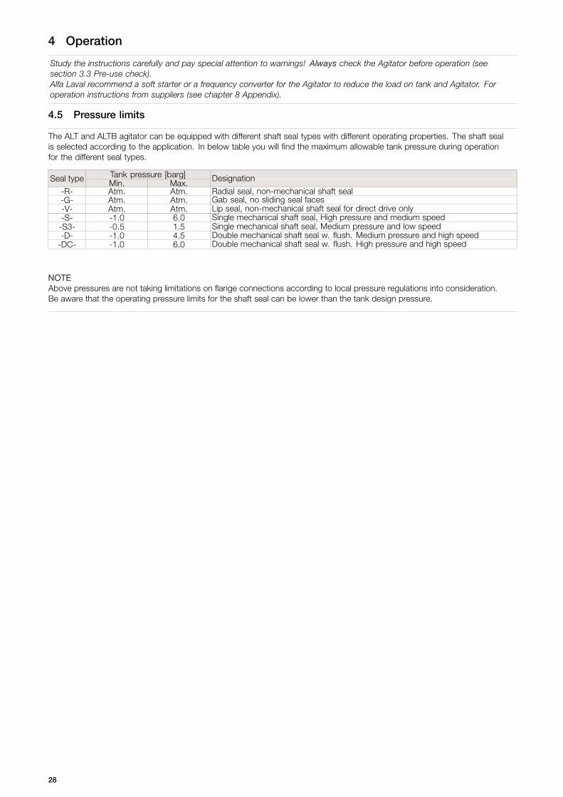
The ALT and ALTB agitator can be equipped with different shaft seal types with different operating properties. The shaft sealis selected according to the application. In below table you will find the maximum allowable tank pressure during operationfor the different seal types.
Tank pressure [barg]Seal type Min. Max. Designation
-R- Atm. Atm. Radial seal, non-mechanical shaft seal-G- Atm. Atm. Gab seal, no sliding seal faces-V- Atm. Atm. Lip seal, non-mechanical shaft seal for direct drive only-S- -1.0 6.0 Single mechanical shaft seal, High pressure and medium speed
-S3- -0.5 1.5 Single mechanical shaft seal, Medium pressure and low speed-D- -1.0 4.5 Double mechanical shaft seal w. flush. Medium pressure and high speed
-DC- -1.0 6.0 Double mechanical shaft seal w. flush. High pressure and high speed
NOTEAbove pressures are not taking limitations on flange connections according to local pressure regulations into consideration.Be aware that the operating pressure limits for the shaft seal can be lower than the tank design pressure.
28

5 Maintenance
For maintenance instructions from suppliers, see chapter 8 Appendix. Always ensure that mounting is according to chapter 6Technical Data. Ensure totally clean surfaces during mounting - also remove remaining loctite residue on threads. Alwaysrefer to tightening torques in section 6.6 Tightening torques for bolt connections.
5.1 General Maintenance
Maintenance of the Agitator should only be performed by authorized personnel.For maintenance instructions from suppliers, see chapter 8 Appendix.Ensure totally clean surfaces during maintenance.
If possible, always dismount the Agitator from tank before dismantling it.Otherwise it is recommended to purchase a shaft retainer tool (see section 7.15 Tools).For lifting instruction, please refer to chapter 3 Installation.
Always read the technical data thoroughly (see chapter 6 Technical Data).Always ensure that the mounting is according to agitator described in section 2.3 Intended use and chapter 6.1 Technical data.Always refer to tightening torques in section 6.6 Tightening torques for bolt connections.Always disconnect the power supply when servicing the Agitator.Always use proper tools.Always replace sealing elements before reassembling.
WARNINGFollow the dismantling and assembly instructions to the letter.After maintenance, section 3.3 Pre-use check must be read thoroughly before operation.NOTEAll scrap must be stored/disposed of in accordance with current rules/directives.Use original Alfa Laval spare parts.
PREVENTIVE MAINTENANCETo ensure that your Alfa Laval machine operates efficiently, it is essential to follow a simple preventive maintenance programme,which will keep your machine in good working conditions. Good maintenance requires careful attention at regular intervals!The following recommended preventive maintenance procedures are based on the average operating conditions of most AlfaLaval machines. However, you will appreciate that a machine, which is subject to rough and dirty conditions, will need morefrequent attention than one working in ideal conditions. We trust that you will adjust your maintenance programme to meet thedemands of your normal operating conditions.
Replace every:3000 hour or
yearly3000 hour orevery 3rd year
6000 hour orevery 3rd year
10000 hour orevery 3rd year
SealingShaft seal- Radial seal: R x- Gab seal: G x- V-ring seal: V xMechanical seal-NOT flushed: S, S3 x-Flushed: DC, D xBearing frameSpider type coupling (if any) xStatic seals xRadial seals xBearings, rpm < 700 xBearings, rpm > 700 xGuidanceBushing: BS3 xBushing: MS2 xBushing: MS2 Replace if temperature > 100°C
29

5 Maintenance
For maintenance instructions from suppliers, see chapter 8 Appendix. Always ensure that mounting is according to chapter 6Technical Data. Ensure totally clean surfaces during mounting - also remove remaining loctite residue on threads. Alwaysrefer to tightening torques in section 6.6 Tightening torques for bolt connections.
5.2 Replacement of drive unit with bearing frame
Step 1Remove shroud, if any.
TD605-1091
2
1
1
Step 2Loosen cap nuts.
CAUTIONIf dismantling motor from gear:- Follow supplier instructions.- Ensure that the gear oil is contained.- A cog wheel may be mounted onto the motor shaft.
TD605-042
1
2
Step 3Release the gear motor from the Agitator.
CAUTIONThere is a spider type coupling mounted onto the gear motor shaft.
Step 4Lift up the drive unit and pull it away.
TD605-043
1
2
Step 51. Loosen coupling screws.2. Pull the coupling of the gear motor shaft. 1
2
TD605-129
30
5 Maintenance
For maintenance instructions from suppliers, see chapter 8 Appendix. Always ensure that mounting is according to chapter 6Technical Data. Ensure totally clean surfaces during mounting - also remove remaining loctite residue on threads. Alwaysrefer to tightening torques in section 6.6 Tightening torques for bolt connections.
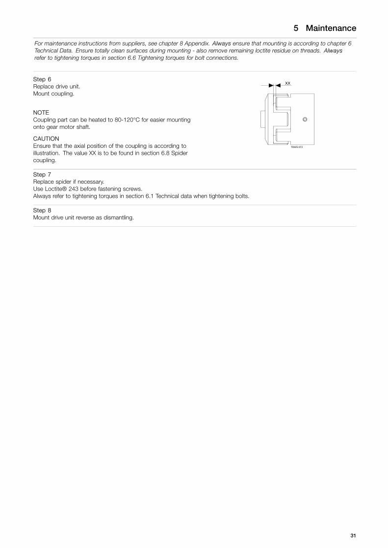
Step 6Replace drive unit.Mount coupling.
NOTECoupling part can be heated to 80-120°C for easier mountingonto gear motor shaft.
CAUTIONEnsure that the axial position of the coupling is according toillustration. The value XX is to be found in section 6.8 Spidercoupling.
XX
TD605-072
Step 7Replace spider if necessary.Use Loctite® 243 before fastening screws.Always refer to tightening torques in section 6.1 Technical data when tightening bolts.
Step 8Mount drive unit reverse as dismantling.
31

5 Maintenance
For maintenance instructions from suppliers, see chapter 8 Appendix. Always ensure that mounting is according to chapter 6Technical Data. Ensure totally clean surfaces during mounting - also remove remaining loctite residue on threads. Alwaysrefer to tightening torques in section 6.6 Tightening torques for bolt connections.
5.3 Replacement of drive unit
Step 1Remove shroud, if any.
TD605-1091
2
1
1
Step 21. Dismantle Agitator from welding flange.2. Lift up Agitator.
TD605-075
1
2
Step 3Support shaft using shaft retainer tool.
NOTEAlfa Laval highly recommends to use shaft retainer tool forinstallation of Agitator within a weight less than 500 kilograms anda shaft diameter between Ø30 and Ø60 (see section 7.15 Tools).
TD60
5-04
5
Step 4Before dismantling drive unit, please see instructions in 5.10 Replacement of shaft seal, type D to 5.13 Replacement of shaftseal, type S3, depending on seal type.
Step 5Loosen cap nuts.
CAUTIONIf dismantling motor from gear:- Follow supplier instructions- Ensure that the gear oil is contained- A cog wheel may be mounted onto the motor shaft. TD605-042
1
2
32

5 Maintenance
For maintenance instructions from suppliers, see chapter 8 Appendix. Always ensure that mounting is according to chapter 6Technical Data. Ensure totally clean surfaces during mounting - also remove remaining loctite residue on threads. Alwaysrefer to tightening torques in section 6.6 Tightening torques for bolt connections.
Step 6
Release the gear motor from the Agitator. Refer to supplierinstructions
TD605-050
CAUTION
There is a Nord-lock® washer mounted on the gear fasteningthe shaft.The washer consists of two parts attached to each other withsome silicone as shown on the picture. It is important that thetwo parts are positioned as shown.
Step 7Lift up the drive unit and pull it away.
TD605-043
1
2
Step 8Replacement drive unit.
Step 9Use Loctite® 243 before fastening screws.Always refer to tightening torques in section 6.6 Tightening torques for bolt connections.
Step 10Mount drive unit reverse as dismantling.
33

5 Maintenance
For maintenance instructions from suppliers, see chapter 8 Appendix. Always ensure that mounting is according to chapter 6Technical Data. Ensure totally clean surfaces during mounting - also remove remaining loctite residue on threads. Alwaysrefer to tightening torques in section 6.6 Tightening torques for bolt connections.
5.4 Replacement of drive unit (Motor and shaft unit)
Step 1Remove shroud, if any.
TD605-1091
2
1
1
Step 2Loosen cap nuts.
TD60
5-04
1
2
1
Step 3Release the motor from the Agitator.
CAUTIONMotor and shaft are one complete unit.
Step 4Lift up the drive unit and pull it away.
Step 5Replace drive unit.
Step 6Use Loctite® 243 before fastening screws.Always refer to tightening torques in section 6.6 Tightening torques for bolt connections.
Step 7Mount drive unit reverse as dismantling.
34
5 Maintenance
For maintenance instructions from suppliers, see chapter 8 Appendix. Always ensure that mounting is according to chapter 6Technical Data. Ensure totally clean surfaces during mounting - also remove remaining loctite residue on threads. Alwaysrefer to tightening torques in section 6.6 Tightening torques for bolt connections.
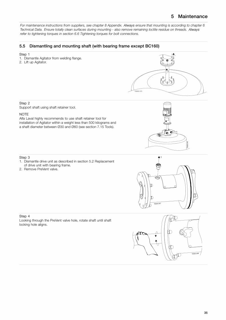
5.5 Dismantling and mounting shaft (with bearing frame except BC160)
Step 11. Dismantle Agitator from welding flange.2. Lift up Agitator.
TD605-075
1
2
Step 2Support shaft using shaft retainer tool.
NOTEAlfa Laval highly recommends to use shaft retainer tool forinstallation of Agitator within a weight less than 500 kilograms anda shaft diameter between Ø30 and Ø60 (see section 7.15 Tools).
TD60
5-04
5
Step 31. Dismantle drive unit as described in section 5.2 Replacement
of drive unit with bearing frame.2. Remove PreVent valve.
TD605-047
1
Step 4Looking through the PreVent valve hole, rotate shaft until shaftlocking hole aligns.
TD605-048
35

5 Maintenance
For maintenance instructions from suppliers, see chapter 8 Appendix. Always ensure that mounting is according to chapter 6Technical Data. Ensure totally clean surfaces during mounting - also remove remaining loctite residue on threads. Alwaysrefer to tightening torques in section 6.6 Tightening torques for bolt connections.
Step 51. Mount retainer bolt tool for shaft locking.2. Remove centre bolt.
NOTEExtra retainer bolt tool can be acquired if needed (see section 7.15Tools) or Spare Part Manual.
TD605-049
1
2
Step 6Remove spider and coupling part.
12
43030007
Step 7Dismantle shaft by mounting extractor bolt tool.Keep turning extractor bolt until shaft is forced from the bearingframe.
NOTEExtra extractor bolt tool can be acquired if needed (see section7.15 Tools or Spare Part Manual).
TD605-051
1
2
Step 8Mount shaft reverse as dismantling
CAUTIONEnsure that oil trap ring, if any, is refitted correct during mounting.
36
5 Maintenance
For maintenance instructions from suppliers, see chapter 8 Appendix. Always ensure that mounting is according to chapter 6Technical Data. Ensure totally clean surfaces during mounting - also remove remaining loctite residue on threads. Alwaysrefer to tightening torques in section 6.6 Tightening torques for bolt connections.
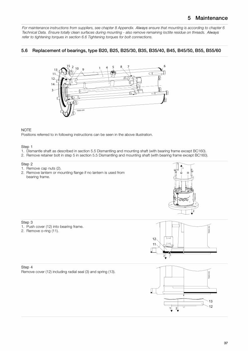
5.6 Replacement of bearings, type B20, B25, B25/30, B35, B35/40, B45, B45/50, B55, B55/60
14
78 613
12
110 92
3
15
11
54
TD605-059
NOTEPositions referred to in following instructions can be seen in the above illustration.
Step 11. Dismantle shaft as described in section 5.5 Dismantling and mounting shaft (with bearing frame except BC160).2. Remove retainer bolt in step 5 in section 5.5 Dismantling and mounting shaft (with bearing frame except BC160).
Step 21. Remove cap nuts (2).2. Remove lantern or mounting flange if no lantern is used from
bearing frame.
TD60
5-05
3
1
2
Step 31. Push cover (12) into bearing frame.2. Remove o-ring (11).
TD60
5-05
4
1211
12
Step 4Remove cover (12) including radial seal (3) and spring (13).
TD60
5-05
5
1 2 1213
37

5 Maintenance
For maintenance instructions from suppliers, see chapter 8 Appendix. Always ensure that mounting is according to chapter 6Technical Data. Ensure totally clean surfaces during mounting - also remove remaining loctite residue on threads. Alwaysrefer to tightening torques in section 6.6 Tightening torques for bolt connections.
Step 5Remove outer circlip (10) carefully. Use suited pliers.
TD60
5-05
6
10
Step 61. Pull out drive shaft (4) including bearings (8, 9).2. Remove o-ring (7)
TD605-057
14
9 4
87
2
1
Step 71. Remove inner circlip (14) carefully. Use suited pliers.2. Remover bearings (8, 9).
TD605-058
1
2
2
14 98
Step 81. Replace bearings (8, 9) and o-rings (6, 7, 11, 15).2. Assembly of bearing frame is reverse as dismantling.
CAUTIONOnly apply force to inner bearing rings when mounting bearings on drive shaft.Only apply force to outer bearing rings when mounting drive shaft with bearings into bearing frame.
38
5 Maintenance
For maintenance instructions from suppliers, see chapter 8 Appendix. Always ensure that mounting is according to chapter 6Technical Data. Ensure totally clean surfaces during mounting - also remove remaining loctite residue on threads. Alwaysrefer to tightening torques in section 6.6 Tightening torques for bolt connections.
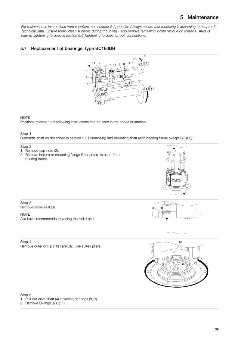
5.7 Replacement of bearings, type BC160DH
TD605-046
11
6
7813 129
3
14
10
12 4
NOTEPositions referred to in following instructions can be seen in the above illustration.
Step 1Dismantle shaft as described in section 5.5 Dismantling and mounting shaft (with bearing frame except BC160).
Step 21. Remove cap nuts (2).2. Remove lantern or mounting flange if no lantern is used from
bearing frame.
TD60
5-05
3
1
2
Step 3Remove radial seal (3).
NOTEAlfa Laval recommends replacing the radial seal. TD605-063
3
Step 4Remove outer circlip (10) carefully. Use suited pliers.
TD60
5-05
6
10
Step 51. Pull out drive shaft (4) including bearings (8, 9).2. Remove O-rings, (7), (11).
39

5 Maintenance
For maintenance instructions from suppliers, see chapter 8 Appendix. Always ensure that mounting is according to chapter 6Technical Data. Ensure totally clean surfaces during mounting - also remove remaining loctite residue on threads. Alwaysrefer to tightening torques in section 6.6 Tightening torques for bolt connections.
Step 61. Remove spring ring (13).2. Remove inner circlip (14) carefully. Use suited pliers.3. Remove bearings (8, 9).
TD605-064
3
2
3
1
148
9
13
Step 71. Replace bearings (8, 9) and o-rings (6, 7, 11).2. Assembly of bearing frame is reverse as dismantling.
CAUTIONOnly apply force to inner bearing rings when mounting bearings on drive shaft.Only apply force to outer bearing rings when mounting drive shaft with bearings into bearing frame.
40

5 Maintenance
For maintenance instructions from suppliers, see chapter 8 Appendix. Always ensure that mounting is according to chapter 6Technical Data. Ensure totally clean surfaces during mounting - also remove remaining loctite residue on threads. Alwaysrefer to tightening torques in section 6.6 Tightening torques for bolt connections.
5.8 Replacement of bearing, type BC160D
12 5 4
6
10
8 7132
111
9
3
14
TD605-061
151617
NOTEPositions referred to in following instructions can be seen in the above illustration.
Step 1Dismantle shaft as described in section 5.5 Dismantling and mounting shaft (with bearing frame except BC160).
Step 21. Remove cap nuts (2).2. Remove lantern or mounting flange if no lantern is used from
bearing frame
TD60
5-05
3
1
2
Step 3Remove radial seal (3).
NOTEAlfa Laval recommends replacing the radial seal. TD605-063
3
Step 4Remove outer circlip (10) carefully. Use suited pliers.
TD60
5-05
6
10
41

5 Maintenance
For maintenance instructions from suppliers, see chapter 8 Appendix. Always ensure that mounting is according to chapter 6Technical Data. Ensure totally clean surfaces during mounting - also remove remaining loctite residue on threads. Alwaysrefer to tightening torques in section 6.6 Tightening torques for bolt connections.
Step 51. Pull out drive shaft (4) including bearings (8a, 9).2. Pull out circlip (12) or let it stay in bearing frame.
NOTEOuter bearing ring (8b) should stay in bearing frame
TD605-068
14
912
48a
8b
Step 61. Remove upper circlip (13) carefully. Use suited pliers2. Push out, using applicable tool, the outer bearing ring (8b).3. Remove o-rings (7, 11).
TD605-069
3
11 13 8b 7
12
3
Step 71. Remove inner circlip (14) carefully. Use suited pliers.2. Remove bearings (8a, 9)
TD605-144
1
2
2
9 12
14
8a
Step 81. Replace bearings (8a, 8b), (9) and o-rings (6, 7, 11).2. Assembly of bearing frame is reverse as dismantling.
CAUTIONOnly apply force to inner bearing rings when mounting bearings on drive shaft.Only apply force to outer bearing rings when mounting drive shaft with bearings into bearing frame
42

5 Maintenance
For maintenance instructions from suppliers, see chapter 8 Appendix. Always ensure that mounting is according to chapter 6Technical Data. Ensure totally clean surfaces during mounting - also remove remaining loctite residue on threads. Alwaysrefer to tightening torques in section 6.6 Tightening torques for bolt connections.
5.9 Replacement of bearings type BC160
TD605-060
1011
25 81
67
149
313
124
NOTEPositions referred to in following instructions can be seen in the above illustration.
Step 1Dismantle drive unit as described in section 5.2 Replacement of drive unit with bearing frame.
Step 21. Remove cap nuts (2).2. Remove lantern or mounting flange if no lantern is used from
bearing frame.
TD60
5-05
3
1
2
Step 3Remove radial seal (3).
NOTEAlfa Laval recommends replacing the radial seal. TD605-063
3
Step 4Remove outer circlip (10) carefully. Use suited pliers.
TD60
5-05
6
10
43

5 Maintenance
For maintenance instructions from suppliers, see chapter 8 Appendix. Always ensure that mounting is according to chapter 6Technical Data. Ensure totally clean surfaces during mounting - also remove remaining loctite residue on threads. Alwaysrefer to tightening torques in section 6.6 Tightening torques for bolt connections.
Step 51. Pull out shaft (4) including bearings (8, 9).2. Remove o-rings (7, 11).
TD605-065
4
911 8
127
1
2
Step 61. Secure shaft (4), without causing surface damage to it.2. Remove coupling (12) by turning it the opposite direction
indicated by arrow on nameplate
TD60
5-06
6
12 1
4
Step 71. Remove bearing (8).2. Remove inner circlip (14) carefully. Use suited pliers.3. Remove bearing (9).
TD605-0671
83
9
14
2
Step 81. Replace bearings (8, 9) and o-rings (6, 7, 11).2. Assembly of bearing frame is reverse as dismantling.
CAUTIONOnly apply force to inner bearing rings when mounting bearings on drive shaft.
44

5 Maintenance
For maintenance instructions from suppliers, see chapter 8 Appendix. Always ensure that mounting is according to chapter 6Technical Data. Ensure totally clean surfaces during mounting - also remove remaining loctite residue on threads. Alwaysrefer to tightening torques in section 6.6 Tightening torques for bolt connections.
5.10 Replacement of shaft seal, type D
TD605-165
20
19
1716
15141312
11
4
98765
123
10
21
22
18
23
NOTETo replace seals easier, use detergent.Ensure subsequent to seal replacement, that all seal faces are totally clean, using alcohol.Positions referred to in following instructions can be seen in the above illustration.
NOTEIf possible, always dismantle the Agitator from the tank before dismounting any parts.
Step 11. Dismantle Agitator from welding flange.2. Lift up Agitator
TD605-075
1
2
Step 2Support shaft using shaft retainer tool.
NOTEAlfa Laval highly recommends to use shaft retainer tool for installation of Agitator within a weight less than 500 kilograms and ashaft diameter between Ø30 and Ø60 (see section 7.15 Tools).
45

5 Maintenance
For maintenance instructions from suppliers, see chapter 8 Appendix. Always ensure that mounting is according to chapter 6Technical Data. Ensure totally clean surfaces during mounting - also remove remaining loctite residue on threads. Alwaysrefer to tightening torques in section 6.6 Tightening torques for bolt connections.
Step 31. Remove flush connections (21).2. Remove guards from lantern.
TD605-084
1
1
2
33
Step 4Move oil trap ring and o-rings, if any, along the shaft.
TD605-087
1
2
31
2
3
Step 51. Loosen pointed screw (19).2. Move the rotary seal housing (20) and rotary seal part (15, 16,
18) carefully along the shaft.
TD605-111
1
2
Step 6Dismantle drive unit as described in section 5.2 Replacement of drive unit with bearing frame.
Step 71. Dismantle shaft as described in section 5.3 Replacement of
drive unit or 5.5 Dismantling and mounting shaft (with bearingframe except BC160), depending on actual agitator type.
2. Remove shaft and rotary seal parts (3, 4) carefully, avoidingcontact.
CAUTIONEnsure rotary seal housing and rotary seal part do NOT fall whenshaft is removed.
TD605-112
46

5 Maintenance
For maintenance instructions from suppliers, see chapter 8 Appendix. Always ensure that mounting is according to chapter 6Technical Data. Ensure totally clean surfaces during mounting - also remove remaining loctite residue on threads. Alwaysrefer to tightening torques in section 6.6 Tightening torques for bolt connections.
Step 81. Remove nuts (23) and washers, securing stationary seal
housing.2. Remove stationary seal housing.
TD605-113
1 2
Step 91. Replace all seal parts.2. Assemble Agitator reverse as dismantling.
CAUTIONEnsure clearance between rotary and stationary seal housing is 2,75 mm.
TD605-125
2.75 0+0.5
47

5 Maintenance
For maintenance instructions from suppliers, see chapter 8 Appendix. Always ensure that mounting is according to chapter 6Technical Data. Ensure totally clean surfaces during mounting - also remove remaining loctite residue on threads. Alwaysrefer to tightening torques in section 6.6 Tightening torques for bolt connections.
5.11 Replacement of shaft seal, type DC
TD605-163
12
345678
1011
14
13129
1516
17
NOTETo replace seals easier, use detergent. Ensure subsequent to seal replacement, that all seal faces are totally clean, using alcohol.Positions referred to in following instructions can be seen in the above illustration.
Step 11. Dismantle Agitator from welding flange.2. Lift up Agitator.
TD605-075
1
2
Step 2Support shaft using shaft retainer tool.
NOTEAlfa Laval highly recommends to use shaft retainer tool forinstallation of Agitator within a weight less than 500 kilograms anda shaft diameter between Ø30 and Ø60 (see section 7.15 Tools).
TD60
5-04
5
48

5 Maintenance
For maintenance instructions from suppliers, see chapter 8 Appendix. Always ensure that mounting is according to chapter 6Technical Data. Ensure totally clean surfaces during mounting - also remove remaining loctite residue on threads. Alwaysrefer to tightening torques in section 6.6 Tightening torques for bolt connections.
Step 31. Remove flush connections (17).2. Remove guards from lantern.
TD605-084
1
1
2
33
Step 41. Rotate distance pieces as shown in Step 10.2. Loosen pointed screws (the pointed screws are not the screws
that fasten the distance pieces).3. Loosen cap nut, securing the seal4. Ensure the seal can move along the shaft (up to 10 mm).
Step 5Move oil trap ring and o-rings, if any, along the shaft.
TD605-087
1
2
31
2
3
Step 61. Remove cap nuts, securing mounting flange.
TD60
5-08
6
1
2
Step 7Dismantle shaft, as described in section 5.3 Replacement of drive unit or 5.5 Dismantling and mounting shaft (with bearingframe except BC160) depending on agitator type and carefully remove lantern.
Step 8Lift lantern and drive unit flange.
49

5 Maintenance
For maintenance instructions from suppliers, see chapter 8 Appendix. Always ensure that mounting is according to chapter 6Technical Data. Ensure totally clean surfaces during mounting - also remove remaining loctite residue on threads. Alwaysrefer to tightening torques in section 6.6 Tightening torques for bolt connections.
Step 9Remove DC seal.
Step 101. Replace sealing.2. Assemble Agitator reverse as dismantling.
4303-0118
During mounting / dismounting Before start
NOTEEnsure distance pieces are oriented correctly during mounting or dismounting.
50

5 Maintenance
For maintenance instructions from suppliers, see chapter 8 Appendix. Always ensure that mounting is according to chapter 6Technical Data. Ensure totally clean surfaces during mounting - also remove remaining loctite residue on threads. Alwaysrefer to tightening torques in section 6.6 Tightening torques for bolt connections.
5.12 Replacement of shaft seal, type S (and type S with dust trap)
TD605-162
123456
7
8
9
10
1112
NOTETo replace seals easier, use detergent.Ensure subsequent to seal replacement, that all seal faces are totally clean, using alcohol.Positions referred to in following instructions can be seen in the above illustration.
NOTESeal is designed for dry running, so a whining noise during operation is quite normal.
TD60
5-14
9
Change seal! Disassembled seal New seal after mounting
NOTEIf possible, always dismantle the Agitator from the tank before dismounting any parts.
51

5 Maintenance
For maintenance instructions from suppliers, see chapter 8 Appendix. Always ensure that mounting is according to chapter 6Technical Data. Ensure totally clean surfaces during mounting - also remove remaining loctite residue on threads. Alwaysrefer to tightening torques in section 6.6 Tightening torques for bolt connections.
Step 11. Dismantle Agitator from welding flange.2. Lift up Agitator.
TD605-075
1
2
Step 2Support shaft using shaft retainer tool.
NOTEAlfa Laval highly recommends to use shaft retainer tool forinstallation of Agitator within a weight less than 500 kilogram and ashaft diameter between Ø30 and Ø60 (see section 7.15 Tools).
TD60
5-04
5
Step 31. Remove guards from lantern.2. Loosen screws, securing the rotating seal part onto the shaft.3. Move the rotating seal part carefully along the shaft.
TD605-145
1
1
1
22
3
Step 41. Remove cap nuts.2. Move the mounting flange, including stationary seal part, by
pulling it carefully along the shaft, avoiding contact.
TD605-146
1
2
52

5 Maintenance
For maintenance instructions from suppliers, see chapter 8 Appendix. Always ensure that mounting is according to chapter 6Technical Data. Ensure totally clean surfaces during mounting - also remove remaining loctite residue on threads. Alwaysrefer to tightening torques in section 6.6 Tightening torques for bolt connections.
Step 5
5a1. Remove screws (9).2. Move retainer ring (3).3. Move stationary seal part (1) and o-ring (2) from mounting
flange.
TD605-093
1
2
3
5b (only for dust trap option)1. Remove screws.2. Move retainer ring.3. Move stationary seal part and o-ring from mounting flange.4. Move dust trap and o-ring from mounting flange.
4303-0158
4
4
3
2
1
Step 6If necessary, dismantle drive unit as described in section 5.2 Replacement of drive unit with bearing frame or 5.3 Replacement ofdrive unit depending on agitator type.
Step 7If necessary, dismantle shaft as described in section 5.3 Replacement of drive unit or 5.5 Dismantling and mounting shaft (withbearing frame except BC160) depending on agitator type and remove lantern with bearing frame.
Step 8Remove oil trap ring, if any.
TD605-087
1
2
31
2
3
Step 9Remove rotary seal part (4, 5, 6, 7, 8, 10, 11), by pulling it carefully along the shaft.
Step 101. Replace all seal parts and o-rings (2, 6, 7).2. Assemble the new rotary seal part on the shaft, by using plenty of detergent.
53

5 Maintenance
For maintenance instructions from suppliers, see chapter 8 Appendix. Always ensure that mounting is according to chapter 6Technical Data. Ensure totally clean surfaces during mounting - also remove remaining loctite residue on threads. Alwaysrefer to tightening torques in section 6.6 Tightening torques for bolt connections.
Step 11Assemble oil trap ring, if any.
Step 12CAUTIONAssemble the stationary seal into the mounting flange by following instructions to the letter.1. Ensure that pins fit onto the groove in the seal.2. Carefully press down the stationary seal part (1, 2) and retainer ring (3) into the mounting flange.3. Use first: DIN7984 or DIN912 M5x12 screws during assembly and afterwards: DIN7984 M5x10, DIN7984 or DIN912 M5x10
screws during assembly – The procedure is used to ensure that the retainer ring (3) is ALWAYS parallel to the mounting flange4. Remove the M5x10 screws and assemble with original fitted screws.
Step 13Assemble mounting flange, shaft and drive unit, following thereverse procedure of dismantling.
Step 14Move the rotating seal part towards the stationary seal part.
1. Tighten the screws (8) securing the seal onto the shaft.
CAUTION!The new seal must be adjusted to the “NEW SET” line.
TD60
5-16
8
54

5 Maintenance
For maintenance instructions from suppliers, see chapter 8 Appendix. Always ensure that mounting is according to chapter 6Technical Data. Ensure totally clean surfaces during mounting - also remove remaining loctite residue on threads. Alwaysrefer to tightening torques in section 6.6 Tightening torques for bolt connections.
5.13 Replacement of shaft seal, type S3
TD605-159
1234567
9
8
NOTETo replace seals easier, use detergent.Ensure subsequent to seal replacement, that all seal faces are totally clean, using alcohol.If possible, always dismantle the Agitator from the tank before dismounting any parts.The seal (see section 2.3 Intended use) is designed for dry running, so a whining noise during operation is quite normal.Positions referred to in following instructions can be seen in the above illustration.
Step 11. Dismantle Agitator from welding flange.2. Lift up Agitator
TD605-075
1
2
Step 2Support shaft using shaft retainer tool.
NOTEAlfa Laval highly recommends to use shaft retainer tool forinstallation of Agitator within a weight less than 500 kilograms anda shaft diameter between Ø30 and Ø60 (see section 7.15 Tools).
TD60
5-04
5
55

5 Maintenance
For maintenance instructions from suppliers, see chapter 8 Appendix. Always ensure that mounting is according to chapter 6Technical Data. Ensure totally clean surfaces during mounting - also remove remaining loctite residue on threads. Alwaysrefer to tightening torques in section 6.6 Tightening torques for bolt connections.
Step 31. Loosen pointed screws (1), securing rotary seal housing onto
the shaft.2. Move the seal housing, including rotary seal part, by pulling it
carefully along the shaft, avoiding contact.
NOTEUse mild detergent to reduce friction.
TD605-127
1
2
Step 41. Remove guards from lantern.2. Remover cap nuts.3. Move the mounting flange, including stationary seal ring,
carefully along the shaft, avoiding contact.
TD605-092
1
12
3
Step 5Move oil trap ring and o-rings, if any, along the shaft.
TD605-087
1
2
31
2
3
Step 61. Push stationary seal ring (7) out of the mounting flange.
TD605-148
Step 7Remove all seal parts from shaft.
56

5 Maintenance
For maintenance instructions from suppliers, see chapter 8 Appendix. Always ensure that mounting is according to chapter 6Technical Data. Ensure totally clean surfaces during mounting - also remove remaining loctite residue on threads. Alwaysrefer to tightening torques in section 6.6 Tightening torques for bolt connections.
Step 81. Replace all seal parts.2. Assemble Agitator reverse as dismantling and position the
rotating seal element according measure x.
Shaft size:Ø30-Ø35, x=37.5Ø40-Ø45, x=40.0Ø50-Ø55, x=42.5Ø60-Ø65, x=47.5Ø70-Ø75, x=55.0Ø80, x=54.0Ø90, x=59.0
1234567
9
8
4303-0172
x +/
- 0.5
57

5 Maintenance
For maintenance instructions from suppliers, see chapter 8 Appendix. Always ensure that mounting is according to chapter 6Technical Data. Ensure totally clean surfaces during mounting - also remove remaining loctite residue on threads. Alwaysrefer to tightening torques in section 6.6 Tightening torques for bolt connections.
5.14 Replacement of shaft seal, type R or G
TD605-150
1
Shaft seal type R
TD60
5-15
5
1
Shaft seal type G
NOTETo replace seals easier, use detergent.Ensure subsequent to seal replacement, that all seal faces are totally clean, using alcohol.Positions referred to in following instructions can be seen in the above illustration.
NOTEIf possible, always dismantle the Agitator from the tank before dismounting any parts.
Step 11. Dismantle Agitator from welding flange.2. Lift up Agitator.
TD605-075
1
2
58

5 Maintenance
For maintenance instructions from suppliers, see chapter 8 Appendix. Always ensure that mounting is according to chapter 6Technical Data. Ensure totally clean surfaces during mounting - also remove remaining loctite residue on threads. Alwaysrefer to tightening torques in section 6.6 Tightening torques for bolt connections.
Step 2Support shaft using shaft retainer tool.
NOTEAlfa Laval highly recommends to use shaft retainer tool forinstallation of Agitator within a weight less than 500 kilogram and ashaft diameter between Ø30 and Ø60 (see section 7.15 Tools).
TD60
5-04
5
Step 31. Remove guards from lantern, if any.2. Remove cap nut from lantern or mounting flange depending
on actual configuration.3. Move the mounting flange including seal carefully along the
shaft.
1
12
3
4303-0054
1
2
Step 4If necessary, dismantle drive unit as described in section 5.2 Replacement of drive unit with bearing frame or 5.3 Replacement ofdrive unit and if required dismantle shaft as described in section 5.3 Replacement of drive unit or 5.5 Dismantling and mountingshaft (with bearing frame except BC160) depending on actual configuration.
Step 5Remove oil trap ring, if any.
TD605-087
1
2
31
2
3
Step 6Push R/G seal (1) out of the mounting flange.
TD605-082
59

5 Maintenance
For maintenance instructions from suppliers, see chapter 8 Appendix. Always ensure that mounting is according to chapter 6Technical Data. Ensure totally clean surfaces during mounting - also remove remaining loctite residue on threads. Alwaysrefer to tightening torques in section 6.6 Tightening torques for bolt connections.
Step 71. Replace R/G seal (1) by pressing it evenly into mounting flange, using a proper tool.
NOTE!Assure correct sealing orientation.
TD605-081TD605-080
Step 8Apply some grease around the shaft at the position of the seal.
Step 9Assemble Agitator reverse as dismantling.
60

5 Maintenance
For maintenance instructions from suppliers, see chapter 8 Appendix. Always ensure that mounting is according to chapter 6Technical Data. Ensure totally clean surfaces during mounting - also remove remaining loctite residue on threads. Alwaysrefer to tightening torques in section 6.6 Tightening torques for bolt connections.
5.15 Replacement of shaft seal, type V
TD605-167
1
NOTETo replace seals easier, use detergent.Ensure subsequent to seal replacement, that all seal faces are totally clean, using alcohol.If possible, always dismantle the Agitator from the tank before dismounting any parts.Positions referred to in following instructions can be seen in the above illustration.
Step 11. Dismantle Agitator from welding flange.2. Lift up Agitator
TD605-075
1
2
Step 2Support shaft using shaft retainer tool.
NOTEAlfa Laval highly recommends to use shaft retainer tool for installation of Agitator within a weight less than 500 kilograms and ashaft diameter between Ø30 and Ø60 (see section 7.15 Tools).
Step 31. Dismantle impeller device.2. Pull V seal (1) along the shaft.
TD60
5-10
8
61

5 Maintenance
For maintenance instructions from suppliers, see chapter 8 Appendix. Always ensure that mounting is according to chapter 6Technical Data. Ensure totally clean surfaces during mounting - also remove remaining loctite residue on threads. Alwaysrefer to tightening torques in section 6.6 Tightening torques for bolt connections.
Step 41. Replace seal.2. Assemble Agitator reverse as dismantling.
62

5 Maintenance
For maintenance instructions from suppliers, see chapter 8 Appendix. Always ensure that mounting is according to chapter 6Technical Data. Ensure totally clean surfaces during mounting - also remove remaining loctite residue on threads. Alwaysrefer to tightening torques in section 6.6 Tightening torques for bolt connections.
5.16 Replacement of wear bushing in intermediate bearing support
Step 1Remove screw(s).Remove cap nuts.
TD605-133
Step 21. Remove o-rings.2. Remove wear bushings.3. Remove o-rings.
TD605-134
1
2
3
Step 31. Replace wear bushing and O-rings (for MS2 type, position
bushings according to shaft diameter).2. Assemble reverse as dismantling.
TD605-137
63

5 Maintenance
For maintenance instructions from suppliers, see chapter 8 Appendix. Always ensure that mounting is according to chapter 6Technical Data. Ensure totally clean surfaces during mounting - also remove remaining loctite residue on threads. Alwaysrefer to tightening torques in section 6.6 Tightening torques for bolt connections.
5.17 Replacement of wear bushing in bottom support
Step 11. Remove screw and lower o-ring.2. Replace o-ring.
4303-0163
1
2
Step 21. Remove wear bushing and upper o-ring.2. Replace wear bushing and o-ring.3. Assemble reverse as dismantling.
4303-0163
1
2
NOTEScrew tightening torque max. 15Nm.
64

6 Technical Data
All dimensions in mm unless otherwise stated.
6.1 Technical data
The Alfa Laval agitator is available in various configurations and is configured to solve the specific application. Therefore specificinformation like weight, size, critical oscillation speed and duties can be found in the supplied Alfa Laval quotation agreement.
Important installation information about weight and mounting angle can be found on the supplied agitator name plate asshown on the illustration.
4303
-000
6
65

6 Technical Data
All dimensions in mm unless otherwise stated.
6.2 Mounting angle for top mounting agitator type ALT
To ensure optimal agitation the top mounted agitator must be installed in the mounting angle specified on the name plate asshown on the illustration and in the off center position required from the Alfa Laval quotation agreement.
S: is the length of the agitator shaft including the impeller.
Y-dim: is the distance from the welding flange face surface and to the tank bottom where the center line of the agitatorintersects with the tank bottom line.
4303
0023
4303
0024
66

6 Technical Data
All dimensions in mm unless otherwise stated.
4303
0025
4303
0026
67

6 Technical Data
All dimensions in mm unless otherwise stated.
6.3 Mounting angle for top mounting agitator type ALTB
To ensure optimal agitation the top mounted agitator must be installed in the mounting angle specified on the name plate asshown on the illustration and in the off center position required from the Alfa Laval quotation agreement.
P1min: is a distance to position the lower impeller to ensure agitation to the lowest fluid level as possible / required foractual application.
Y-dim: is the distance from the welding flange face surface and to the tank bottom where the center line of the agitatorintersects with the tank bottom line.
43030027 43030028
43030029 43030030
68

6 Technical Data
All dimensions in mm unless otherwise stated.
6.4 Connecting flush – Seal type D
Flush connection:In and out: Male 1/2"-14 BSP (ISO 7/1-Rp)Flushing pressure max. 2.0 bar(g)
Flush media pressure recommendation to prevent flush media contamination by the product media:(flush media pressure > tank operating pressure)- Flushing pressure ≥ (Tank operating pressure + 0.1 bar)
NOTETank pressure cannot be higher than 1.9 bar(g) due to the maximum flushing pressure. If higher tank pressure is needed thenext flush media pressure recommendation must be followed.
Flush media pressure recommendation to prevent product media contamination by the flush media:(tank operating pressure > flush media pressure)- Flushing pressure ≤ (Tank operating pressure – 0.1 bar)- (Tank operating pressure – Flushing pressure) ≤ 2.5 bar
NOTEIf the tank pressure is more than 2,5 bar(g) greater than the flushing pressure, there will be a risk of dry running on the primaryseal faces due to the atmosphere in the tank will push the flush media out of the primary seal faces.
Flush media flow recommendation:- Flushing flow rate > 0.25 ltr/min- Lower flushing flow rate is allowed as long as the temperature difference between in- and outlet is < 10°C
Flush media type recommendation:- White oils- Water- Wet steam- Alcohol
69

6 Technical Data
All dimensions in mm unless otherwise stated.
Flush media type recommendation:- Always use appropriately in- and outlet temperatures given for current seal elastomers- Inlet temperature to be 15°C below actual fluid boiling point (temperature and
pressure dependent)- Always use wet steam (H2O) if steam is used as flushing fluid- Inlet temperature ≤ 121°C
Sterile barrier at seal type D and DC:- Use a sterile supply system with preferred sterilization temperature and water / wet
steam as flush type and ensure that above recommendations are followed
Ensure flush connections are not installed or oriented in such way that air pockets will appear. In some cases initial air pocketsnear the seal surfaces (e.q. at bottom mounted agitators ALB) cannot be avoided. It has been tested and verified thatan initial flow rate without air at 5 ltr/min lasting for 30 seconds while the agitator is running ensures that all air in seal andflushing chamber will be flushed out.
TD605-078
TD605-079
NOTEAlfa Laval recommends installing a pressure relief valve to ensure pressure never exceed specifications.Alfa Laval recommends installing a non-return valve onto the inlet connection, to ensure that the seal never runs dry.If higher flushing pressure is desired, please contact Alfa Laval for advice.
70
6 Technical Data
All dimensions in mm unless otherwise stated.
6.5 Connecting flush – Seal type DC
Flush connection:In and out: Male 1/2"-14 BSP (ISO 7/1-Rp)Flushing pressure max. 7.0 bar(g)
Flush media pressure recommendation to prevent flush media contamination by the product media:(flush media pressure > tank operating pressure)- Flushing pressure ≥ (Tank operating pressure + 0.1 bar)
Flush media pressure recommendation to prevent product media contamination by the flush media:(tank operating pressure > flush media pressure)- Flushing pressure ≤ (Tank operating pressure – 0.1 bar)- (Tank operating pressure – Flushing pressure) ≤ 2.5 bar
NOTEIf the tank pressure is more than 2.5 bar(g) greater than the flushing pressure, there will be a risk of dry running on the primaryseal faces due to the atmosphere in the tank will push the flush media out of the primary seal faces.
Flush media flow recommendation:- Flushing flow rate > 0.25 ltr/min- Lower flushing flow rate is allowed as long as the temperature difference between in- and outlet is < 10°C
71

6 Technical Data
All dimensions in mm unless otherwise stated.
Flush media type recommendation:- White oils- Water- Wet steam- Alcohol
Flush media type recommendation:- Always use appropriately in- and outlet temperatures given for current seal elastomers- Inlet temperature to be 15°C below actual fluid boiling point (temperature and
pressure dependent)- Always use wet steam (H2O) if steam is used as flushing fluid- Inlet temperature ≤ 121°C
Sterile barrier at seal type D and DC:- Use a sterile supply system with preferred sterilization temperature and water / wet
steam as flush type and ensure that above recommendations are followed
Ensure that connection of outlet and inlet is correct, with regard to Agitator rotation direction!Ensure that the distance pieces (1) on the seal are mounted as shown on illustration.
1
IN
TD605-170
OUT
NOTEAlfa Laval recommends installing a pressure relief valve to ensure pressure never exceed specifications.Alfa Laval recommends installing a non-return valve onto the inlet connection, to ensure that the seal never runs dry.If higher flushing pressure is desired, please contact Alfa Laval for advice.
72

6 Technical Data
All dimensions in mm unless otherwise stated.
6.6 Tightening torques for bolt connections
CAUTIONUse Loctite® before fastening.Do NOT use air powered tools.
M4 M5 M6 M8 M10 M12 M14 M16 M18 M20 M22 M24
3Nm 6Nm 11Nm 26Nm 51Nm 88Nm 141Nm 218Nm 308Nm 439Nm 582Nm 724Nm
73

6 Technical Data
All dimensions in mm unless otherwise stated.
6.7 Shaft alignment
Shaft to be aligned in bearing frame or in gear motor.
RPM up to: 50 100 500 1000 2800
U (max radial tolerance, ALT) 0.4 0.3 0.2 0.1 0.05
U (max radial tolerance, ALTB) 2.0 1.5 1.0
U
TD605-106
4303-0056
After propellers has been welded onto the shaft and / or two shaft parts has been welded together - the shaft must bealigned. If the shafts has been welded according to Alfa Lavals recommendations shown below – the required alignment willbe very little as the amount of introduced heat to the shaft is minimized and due to the fact that all shafts has been alignedbefore delivery from Alfa Laval.
“All-weld shaft connections and propellers to shaft with one welding seam at a time, cool with air and continue with onewelding until welding is according to illustration. Use welding procedures which introduce as less heat, tension and bendingto the shaft as possible.”
Required tool:1. A gas-welding torch supplied with a mixture of Acetylene and Oxygen gas.2. A dial indicator.
74

6 Technical Data
All dimensions in mm unless otherwise stated.
Procedure:1. Alignment of the shaft is carried out in steps from the bearing frame / gear motor and down to the shaft end.2. If the shaft has been exposed to uneven heat around “A” (due to welding of shaft connection or welding of propeller
onto shaft) a possible bend can be introduced around “A”.3. The dial indicator is located about 500-2000 mm below “A” (but above the next bend “B”) and the shaft is rotated until
the shaft is pointing to the left as shown on the picture.4. The welding torch is used on the opposite site of the bend (the right side of the shaft in this example) about 25-50 mm
further up or down from the welding area “A”. The welding torch is positioned very near the shaft surface without moving itand the surface of the shaft is rapidly heated up (1-10 seconds depending on shaft bend) until a Ø2-10 mm red spot isobserved. Observing the dial indicator the shaft will, during the heating process, bend even more to the wrong direction butduring cooling it bends back to a “more” align position.
5. The shaft is cooled down with compressed air until the temperature of the part of the shaft around A is the same as the restof the shaft and the surrounding temperature (2-10 minutes depending on amount of heat introduced).
6. Step 3), 4) and 5) are repeated until the alignment is according the specified “U” (which is a function of speed andagitator type).
7. The next position “B” where the shaft has been exposed to uneven heat is located (due to welding of shaft connectionor welding of propeller onto shaft).
8. The dial indicator is located 500-2000 mm below “B” (but above the next bend) or at the shaft end if the shaft does not haveany other bends and the shaft is rotated until the shaft is pointing to the right as shown on the picture.
9. The welding torch is used on the opposite site of the bend (the left side of the shaft in this example) about 25-50 mm furtherup or down from the welding area. The welding torch is positioned very near shaft surface without moving it and the surfaceof the shaft is rapidly heated up (1-10 seconds depending on shaft bend) until a Ø2-10 mm red spot is observed.
10. The shaft is cooled down with compressed air until the temperature of the part of the shaft around A is the same as the restof the shaft and the surrounding temperature (2-10 minutes depending on amount of heat introduced).
11. Step 8), 9) and 10) are repeated until the alignment is according the specified “U” (which is a function of speed andagitator type).
12. The spot areas where the shaft has been heated and aligned using the welding torch must be cleaning using chemicalpickling and or mechanical abrasive polishing.
75

6 Technical Data
All dimensions in mm unless otherwise stated.
6.8 Spider coupling
Axial alignment and tooth thickness [mm]:
Bearing frame type:
BC160/35BC160D/30
BC160DH/30
B20B25
B25/30
B35B35/40
B45B45/50
B55B55/60
X: 2 2 2.5 3 3.5
Ynew: 8.5 8.5 10.9 13.3 17.7
Ymin: 5.6 5.6 7.9 10.3 13.7
X
TD605-070
Y
CAUTIONDuring check of spider ensure that all dust is removed before reassembly.
76

6 Technical Data
All dimensions in mm unless otherwise stated.
6.9 Bottom support alignment
Shaft alignment (radial and angle misalignment) must be according to values shown in table below.
Shaft length,[mm] 500-1000 2000 3000 4000 5000 6000 7000 7001-15000
Z, [mm], (max) 4 8 10 12 15 22 30 40α, [°], (+/- 1.5°) 12 12 12 12 12 12 12 12
Z
4303-0164
α
77

6 Technical Data
All dimensions in mm unless otherwise stated.
6.10 Bottom support positioning
Shaft diameter, [mm] Ø30-Ø65 Ø70-Ø90X, Bushing height 65 75
Ensure that bushing can be removed after position andwelding-in steady bearing stand: Y>X (also depending on tankbottom angle).
The distance Lx can be found in the Alfa Laval quotationagreement.
LxY
X
4303-0165
78

6 Technical Data
All dimensions in mm unless otherwise stated.
6.11 Storage
Store the Agitator in dry and clean environments.
Rotate shaft every second week to ensure seal faces do not stick together.
79

7 Part lists, part drawings and service kits
Agitator type ALT / ALTB, main components - Drive end
7.1 Agitator Main Components, Drive end
80

7 Part lists, part drawings and service kits
Agitator type ALT / ALTB, main components - Drive end
Parts list
Pos. Qty Denomination
1 1 GR gear motor, hollow shaft2 1 GP gear motor, hollow shaft3 1 GR gear motor, output shaft4 1 GC gear motor, output shaft5 ♦ 1 Bearing frame B20, B25, B25/30,
B35, B35/40, B45, B45/50, B55,B55/60
6 ♦ 1 Bearing frame, BC160/35,BC160D/30, BC160DH/30
7 ♦ 1 Shaft seal type R8 ♦ 1 Shaft seal type G9 ♦ 1 Shaft seal type V10 ♦ 1 Shaft seal type S11 ♦ 1 Shaft seal type S313 1 O-ring16 X Screw17 1 Welding flange18 1 Mounting flange, standard19 1 Mounting flange, raised20 X Stud21 X Cap nut22 X Washer23 X Screw24 1 Washer, Nord Lock25 1 Fixing element26 1 Lantern, complete27 1 Drive unit flange34 1 Flat gasket35 1 Coupling36 1 Motor and shaft unit37 1 Motor38 ♦ 1 Shaft seal type D39 ♦ 1 Shaft seal type DC
¬ Article number available upon request by serial number or article number of the agitator.
◆ Article number is to be found in the Spare part manual available from the on-line Alfa Laval product catalogue Anytime or theClose at hand spare part catalogue.
X Quantity may vary depending on Agitator type, will be informed upon request.
81

7 Part lists, part drawings and service kits
Agitator type ALT / ALTB, main components - Wet end
7.2 Agitator Main Components, Wet end
4303-0139
82

7 Part lists, part drawings and service kits
Agitator type ALT / ALTB, main components - Wet end
Parts list
Pos. Qty Denomination
12 ♦ 1 O-ring14 1 Shaft15 1 Parrallel key16 X Screw28 1 Impeller device, EnSaFoil (ESF or
ESFL), w. thread29 1-10 Impeller device, EnSaFoil, (ESF or
ESFL), w. screws or welded30 1-10 Impeller device, EnSaFerm,
(ESFm), w. screws or welded31 1 Impeller device, Low level, (LLI),
w. screws or welded40 ♦ 1 Shaft and coupling unit41 1 O-ring42 X Welded shaft coupling43 X Sleeve for welded shaft coupling44 X Sleeve coupling45 X Parrallel key for sleeve coupling46 X Screw47 ♦ Intermediate support48 ♦ Bottom support, type 3
¬ Article number available upon request by serial number or article number of the agitator.
◆ Article number is to be found in the Spare part manual available from the on-line Alfa Laval product catalogue Anytime or theClose at hand spare part catalogue.
83

7 Part lists, part drawings and service kits
Bearing frame, B20, B25, B25/30, B35, B35/40, B45, B45/50, B55, B55/60
7.3 Bearing frame, B20, B25, B25/30, B35, B35/40, B45, B45/50, B55, B55/60
4303
-001
4
84

7 Part lists, part drawings and service kits
Bearing frame, B20, B25, B25/30, B35, B35/40, B45, B45/50, B55, B55/60
Parts list
Pos. Qty Denomination
1 1 Bearing frame - housing2 1 Drive shaft3 1 Coupling4 1 Cover5 1 Pin6 2 Pin7 1 Tool, retainer bolt8 1 Spider9 1 Bearing10 1 Bearing11 1 PreVent Valve12 1 Seal, radial13 1 O-ring14 1 O-ring15 1 O-ring16 1 O-ring17 1 Circlip, inner18 1 Spring, wave19 1 Screw20 1 Extractor bolt21 8 Cap nut22 2 Pin23 1 Circlip, outer25 1 Washer
Service kits
Denomination B20 B25 B25/30 B35
Assembly Kit Assembly Kit, Bearing frame B20, B25, B25/30, B35 . . . . . . . . . TE261301266B TE261301267B TE2613066880 TE261301269C
◆ Article number is to be found in the Spare part manual available from the on-line Alfa Laval product catalogue Anytime or theClose at hand spare part catalogue.
85

7 Part lists, part drawings and service kits
Bearing frame, B20, B25, B25/30, B35, B35/40, B45, B45/50, B55, B55/60
4303
-001
4
86

7 Part lists, part drawings and service kits
Bearing frame, B20, B25, B25/30, B35, B35/40, B45, B45/50, B55, B55/60
Parts list
Pos. Qty Denomination
1 1 Bearing frame - housing2 1 Drive shaft3 1 Coupling4 1 Cover5 1 Pin6 2 Pin7 1 Tool, retainer bolt8 1 Spider9 1 Bearing10 1 Bearing11 1 PreVent Valve12 1 Seal, radial13 1 O-ring14 1 O-ring15 1 O-ring16 1 O-ring17 1 Circlip, inner18 1 Spring, wave19 1 Screw20 1 Extractor bolt21 8 Cap nut22 2 Pin23 1 Circlip, outer25 1 Washer
Service kits
Denomination B35/40 B45 B45/50 B55 B55/60
Assembly Kit Assembly Kit, Bearing frame B35/40, B45,
B45/50, B55, B55/60 . . . . . . . . . . . . . . . . . . . . . . . . TE261304566B TE261301100B TE261305434A TE261301102B TE2613065530
◆ Article number is to be found in the Spare part manual available from the on-line Alfa Laval product catalogue Anytime or theClose at hand spare part catalogue.
87

7 Part lists, part drawings and service kits
Bearing frame BC160/35, BC160D/30, BC160DH/30
7.4 Bearing frame BC160/35, BC160D/30, BC160DH/30
4303-0059
88

7 Part lists, part drawings and service kits
Bearing frame BC160/35, BC160D/30, BC160DH/30
Parts list
Pos. Qty Denomination
1 1 Bearing frame - housing2 1 Drive shaft3 1 Coupling4 1 Pin5 2 Pin6 1 Tool, retainer bolt7 1 Spider8 1 Bearing9 1 Bearing10 1 PreVent valve11 1 Seal, radial12 1 O-ring13 1 O-ring14 1 O-ring15 1 Circlip, inner16 1 Seeger ring17 1 Screw18 1 Extractor bolt19 8 Cap nut20 1 Circlip, outer22 7 Circlip, outer23 1 Circlip, inner
Service kits
DenominationBC160/35(right) BC160/35 (left) BC160D/30 BC160DH/30
Assembly Kit Assembly Kit, Bearing frame BC160/35, BC160D/30,
BC160DH/30 . . . . . . . . . . . . . . . . . . . . . . . . . . . . . . . . . . . . . . . . . . . . . . . . . . TE261303783B TE261303783B TE261303672B TE2613071680
◆ Article number is to be found in the Spare part manual available from the on-line Alfa Laval product catalogue Anytime or theClose at hand spare part catalogue.
89

7 Part lists, part drawings and service kits
Shaft seal, type S
7.5 Shaft seal, type S
4303
-003
4
90

7 Part lists, part drawings and service kits
Shaft seal, type S
Parts list
Pos. Qty Denomination
1 1 S seal♦ 1 S seal
2 1 Oil trap3 ♦ 2 O-ring4 1 Ring, retainer5 4 Screw
Service kits
Denomination size: Ø30 size: Ø35 size: Ø40 size: Ø45
Seal Kits Seal kit, S, C/SiC, EPDM . . . . . . . . . . . . . . . . . . . . . . . . . . . . . . . . . . . . . . TE2613000040 TE2613000041 TE2613000042 TE2613000043♦ Seal kit, S, C/SiC, FPM . . . . . . . . . . . . . . . . . . . . . . . . . . . . . . . . . . . . . . . . TE2613000031 TE2613000032 TE2613000033 TE2613000034
Parts list
Pos. Qty Denomination
1 1 S seal♦ 1 S seal
2 1 Oil trap3 ♦ 2 O-ring4 1 Ring, retainer5 4 Screw
Service kits
Denomination size: Ø50 size: Ø60 size: Ø70 size: Ø80
Seal Kits Seal kit, S, C/SiC, EPDM . . . . . . . . . . . . . . . . . . . . . . . . . . . . . . . . . . . . . . TE2613000045 TE2613000046 TE2613000047 TE2613000038♦ Seal kit, S, C/SiC, FPM . . . . . . . . . . . . . . . . . . . . . . . . . . . . . . . . . . . . . . . . TE2613000035 TE2613000036 TE2613000037 TE2613000048
Parts list
Pos. Qty Denomination
1 1 S seal♦ 1 S seal
2 1 Oil trap3 ♦ 2 O-ring4 1 Ring, retainer5 4 Screw
Service kits
Denomination size: Ø90
Seal Kits Seal kit, S, C/SiC, EPDM . . . . . . . . . . . . . . . . . . . . . . . . . . . . . . . . . . . . . . TE2613000049♦ Seal kit, S, C/SiC, FPM . . . . . . . . . . . . . . . . . . . . . . . . . . . . . . . . . . . . . . . . TE2613000039
91

7 Part lists, part drawings and service kits
Shaft seal, type S with dust trap
7.6 Shaft seal, type S with dust trap
4303
-015
7
92

7 Part lists, part drawings and service kits
Shaft seal, type S with dust trap
Parts list
Pos. Qty Denomination
1 1 S seal♦ 1 S seal
2 1 Oil trap3 ♦ 2 O-ring4 1 Ring, retainer5 4 Screw6 1 Dust trap7 1 Spacer ring8 1 O-ring
Service kits
Denomination size: Ø30 size: Ø40 size: Ø50
Seal Kits Seal kit, S, C/SiC, EPDM . . . . . . . . . . . . . . . . . . . . . . . . . . . . . . . . . . . . . . TE2613000040 TE2613000042 TE2613000045♦ Seal kit, S, C/SiC, FPM . . . . . . . . . . . . . . . . . . . . . . . . . . . . . . . . . . . . . . . . TE2613000031 TE2613000033 TE2613000035
93

7 Part lists, part drawings and service kits
Shaft seal, type S3
7.7 Shaft seal, type S3
4303
-003
5
94

7 Part lists, part drawings and service kits
Shaft seal, type S3
Parts list
Pos. Qty Denomination
1 1 S3 seal♦ 1 S3 seal
2 1 Oil trap3 ♦ 2 O-ring4 1 Locking pin5 1 Locking plate6 1 Screw
Service kits
Denomination size: Ø30 size: Ø35 size: Ø40 size: Ø45
Seal Kits Seal Kit, S3, C/SiC, EPDM . . . . . . . . . . . . . . . . . . . . . . . . . . . . . . . . . . . . . TE2613000087 TE2613000090 TE2613000091 TE2613000093♦ Seal Kit, S3, C/SiC, FPM . . . . . . . . . . . . . . . . . . . . . . . . . . . . . . . . . . . . . . TE2613000104 TE2613000106 TE2613000107 TE2613000108
Parts list
Pos. Qty Denomination
1 1 S3 seal♦ 1 S3 seal
2 1 Oil trap3 ♦ 2 O-ring4 1 Locking pin5 1 Locking plate6 1 Screw
Service kits
Denomination size: Ø50 size: Ø55 size: Ø60 size: Ø65
Seal Kits Seal Kit, S3, C/SiC, EPDM . . . . . . . . . . . . . . . . . . . . . . . . . . . . . . . . . . . . . TE2613000095 TE2613000096 TE2613000098 TE2613000099♦ Seal Kit, S3, C/SiC, FPM . . . . . . . . . . . . . . . . . . . . . . . . . . . . . . . . . . . . . . TE2613000109 TE2613000110 TE2613000112 TE2613000113
95

7 Part lists, part drawings and service kits
Shaft seal, type S3
4303
-003
5
96

7 Part lists, part drawings and service kits
Shaft seal, type S3
Parts list
Pos. Qty Denomination
1 1 S3 seal,♦ 1 S3 seal
2 1 Oil trap3 ♦ 2 O-ring, FPM4 1 Locking pin5 1 Locking plate6 1 Screw
Service kits
Denomination size: Ø70 size: Ø75 size: Ø80 size: Ø90
Seal Kits Seal Kit, S3, C/SiC, EPDM . . . . . . . . . . . . . . . . . . . . . . . . . . . . . . . . . . . . . TE2613000100 TE2613000101 TE2613000102 TE2613000103♦ Seal Kit, S3, C/SiC, FPM . . . . . . . . . . . . . . . . . . . . . . . . . . . . . . . . . . . . . . TE2613000116 TE2613000117 TE2613000118 TE2613000120
97

7 Part lists, part drawings and service kits
Shaft seal, type D
7.8 Shaft seal, type D
4303
-001
9
98

7 Part lists, part drawings and service kits
Shaft seal, type D
Parts list
Pos. Qty Denomination
1 ♦ 1 Seal 1 Seal 1 Seal 1 Seal
2 ♦ 1 Seal 1 Seal
3 1 Ring, counter**4 1 Ring, counter5 4 Pin6 1 Screw7 1 O-ring
♦ 1 O-ring8 1 O-ring
♦ 1 O-ring9 1 Spacer10 2 Flush, connection 1/2"-14 BSP11 4 Stud12 4 Nut13 1 Seal housing14 1 Oil trap15 ♦ 2 O-ring, FPM
Service kits
Denomination Ø30 Ø40
Seal kits Seal Kit, D, C/SiC-C/SiC, FPM . . . . . . . . . . . . . . . . . . . . . . . . . . . . . . . . TE2613000121 TE2613000122♦ Seal Kit, D, C/SiC-C/SiC, EPDM . . . . . . . . . . . . . . . . . . . . . . . . . . . . . . . TE2613000123 TE2613000124 Seal Kit, D, SiC/SiC-C/SiC, FPM . . . . . . . . . . . . . . . . . . . . . . . . . . . . . . TE2613000125 TE2613000126 Seal Kit, D, SiC/SiC-C/SiC, EPDM . . . . . . . . . . . . . . . . . . . . . . . . . . . . . TE2613000127 TE2613000128
99

7 Part lists, part drawings and service kits
Shaft seal, type DC
7.9 Shaft seal, type DC
4303
-002
0
100

7 Part lists, part drawings and service kits
Shaft seal, type DC
Parts list
Pos. Qty Denomination
1 1 DC seal♦ 1 DC seal 1 DC seal 1 DC seal
2 2 Flush3 4 Cap nut4 4 Washer5 4 Stud6 1 Oil trap7 ♦ 2 O-ring
Service kits
Denomination size: Ø30 size: Ø35 size: Ø40 size: Ø45
Seal kits Seal Kit, DC, C/SiC-C/SiC, EPDM . . . . . . . . . . . . . . . . . . . . . . . . . . . . . TE2613000137 TE2613000138 TE2613000139 TE2613000140♦ Seal Kit, DC, C/SiC-C/SiC, FPM . . . . . . . . . . . . . . . . . . . . . . . . . . . . . . . TE2613000144 TE2613000145 TE2613000146 TE2613000147 Seal Kit, DC, SiC/SiC-C/SiC, EPDM . . . . . . . . . . . . . . . . . . . . . . . . . . . TE2613000151 TE2613000152 TE2613000153 TE2613000154 Seal Kit, DC, SiC/SiC-C/SiC, FPM . . . . . . . . . . . . . . . . . . . . . . . . . . . . . TE2613000158 TE2613000159 TE2613000160 TE2613000161
Parts list
Pos. Qty Denomination
1 1 DC seal♦ 1 DC seal 1 DC seal 1 DC seal
2 2 Flush6 1 Oil trap7 ♦ 2 O-ring
Service kits
Denomination size: Ø50 size: Ø55 size: Ø60 size: Ø70
Seal kits Seal Kit, DC, C/SiC-C/SiC, EPDM . . . . . . . . . . . . . . . . . . . . . . . . . . . . . TE2613000141 TE2613000142 TE2613000143 9615478601♦ Seal Kit, DC, C/SiC-C/SiC, FPM . . . . . . . . . . . . . . . . . . . . . . . . . . . . . . . TE2613000148 TE2613000149 TE2613000150 9615478701 Seal Kit, DC, SiC/SiC-C/SiC, EPDM . . . . . . . . . . . . . . . . . . . . . . . . . . . TE2613000155 TE2613000156 TE2613000157 9615478801 Seal Kit, DC, SiC/SiC-C/SiC, FPM . . . . . . . . . . . . . . . . . . . . . . . . . . . . . TE2613000162 TE2613000163 TE2613000164 9615478901
101

7 Part lists, part drawings and service kits
Shaft seal, type DC
4303
-002
0
102

7 Part lists, part drawings and service kits
Shaft seal, type DC
Parts list
Pos. Qty Denomination
1 1 DC seal♦ 1 DC seal 1 DC seal 1 DC seal
2 2 Flush3 4 Cap nut4 4 Washer5 4 Stud6 1 Oil trap7 ♦ 2 O-ring
Service kits
Denomination size: Ø80 size: Ø90
Seal kits Seal Kit, DC, C/SiC-C/SiC, EPDM . . . . . . . . . . . . . . . . . . . . . . . . . . . . . 9615479001 9615479401♦ Seal Kit, DC, C/SiC-C/SiC, FPM . . . . . . . . . . . . . . . . . . . . . . . . . . . . . . . 9615479101 9615479501 Seal Kit, DC, SiC/SiC-C/SiC, EPDM . . . . . . . . . . . . . . . . . . . . . . . . . . . 9615479201 9615479601 Seal Kit, DC, SiC/SiC-C/SiC, FPM . . . . . . . . . . . . . . . . . . . . . . . . . . . . . 9615479301 9615479701
103

7 Part lists, part drawings and service kits
Shaft seal, type R
7.10 Shaft seal, type R
4303
-003
6
104

7 Part lists, part drawings and service kits
Shaft seal, type R
Parts list
Pos. Qty Denomination
1 1 Radial seal♦ 1 Radial seal
2 1 Oil trap3 ♦ 2 O-ring, FPM
Service kits
Denomination size: Ø20 size: Ø25 size: Ø30 size: Ø35
Seal kits Seal Kit, Radial, FPM . . . . . . . . . . . . . . . . . . . . . . . . . . . . . . . . . . . . . . . . . . TE2613000001 TE2613000002 TE2613000003 TE2613000004♦ Seal Kit, Radial, FPM . . . . . . . . . . . . . . . . . . . . . . . . . . . . . . . . . . . . . . . . . . TE2613000190
Parts list
Pos. Qty Denomination
1 1 Radial seal♦ 1 Radial seal
2 1 Oil trap3 ♦ 2 O-ring
Service kits
Denomination size: Ø40 size: Ø45 size: Ø50 size: Ø55
Seal kits Seal Kit, Radial, FPM . . . . . . . . . . . . . . . . . . . . . . . . . . . . . . . . . . . . . . . . . . TE2613000005 TE2613000006 TE2613000194 TE2613000008♦ Seal Kit, Radial, FPM . . . . . . . . . . . . . . . . . . . . . . . . . . . . . . . . . . . . . . . . . . TE2613000192 TE2613000193 TE2613000007
105

7 Part lists, part drawings and service kits
Shaft seal, type R
4303
-003
6
106

7 Part lists, part drawings and service kits
Shaft seal, type R
Parts list
Pos. Qty Denomination
1 1 Radial seal2 1 Oil trap3 2 O-ring
Service kits
Denomination size: Ø60 size: Ø65 size: Ø70 size: Ø75
Seal kits Seal Kit, Radial, FPM . . . . . . . . . . . . . . . . . . . . . . . . . . . . . . . . . . . . . . . . . . TE2613000009 TE2613000010 TE2613000011 TE2613000012
Parts list
Pos. Qty Denomination
1 1 Radial seal2 1 Oil trap3 2 O-ring
Service kits
Denomination size: Ø80 size: Ø90
Seal kits Seal Kit, Radial, FPM . . . . . . . . . . . . . . . . . . . . . . . . . . . . . . . . . . . . . . . . . . TE2613000013 TE2613000014
107

7 Part lists, part drawings and service kits
Shaft seal, type G
7.11 Shaft seal, type G
4303
-003
7
108

7 Part lists, part drawings and service kits
Shaft seal, type G
Parts list
Pos. Qty Denomination
1 1 Gab seal♦ 1 Gab seal
2 1 Oil trap3 ♦ 2 O-ring
Service kits
Denomination size: Ø20 size: Ø25 size: Ø30 size: Ø35
Seal kits Seal Kit, Gap, PTFE . . . . . . . . . . . . . . . . . . . . . . . . . . . . . . . . . . . . . . . . . . . . TE2613000015 TE2613000016 TE2613000017 TE2613000018♦ Seal Kit, Gap, PTFE . . . . . . . . . . . . . . . . . . . . . . . . . . . . . . . . . . . . . . . . . . . . TE2613000195
Parts list
Pos. Qty Denomination
1 1 Gab seal♦ 1 Gab seal
2 1 Oil trap3 ♦ 2 O-ring
Service kits
Denomination size: Ø40 size: Ø45 size: Ø50 size: Ø55
Seal kits Seal Kit, Gap, PTFE . . . . . . . . . . . . . . . . . . . . . . . . . . . . . . . . . . . . . . . . . . . . TE2613000019 TE2613000020 TE2613000198 TE2613000022♦ Seal Kit, Gap, PTFE . . . . . . . . . . . . . . . . . . . . . . . . . . . . . . . . . . . . . . . . . . . . TE2613000196 TE2613000197 TE2613000021
109
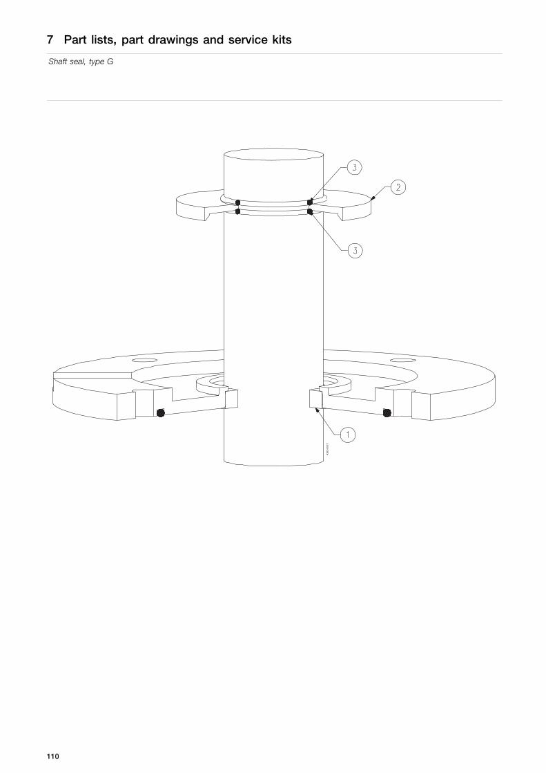
7 Part lists, part drawings and service kits
Shaft seal, type G
4303
-003
7
110

7 Part lists, part drawings and service kits
Shaft seal, type G
Parts list
Pos. Qty Denomination
1 1 Gab seal2 1 Oil trap3 2 O-ring
Service kits
Denomination size: Ø60 size: Ø65 size: Ø70 size: Ø75
Seal kits Seal Kit, Gap, PTFE . . . . . . . . . . . . . . . . . . . . . . . . . . . . . . . . . . . . . . . . . . . . TE2613000023 TE2613000024 TE2613000025 TE2613000026
Parts list
Pos. Qty Denomination
1 1 Gab seal, PTFE2 1 Oil trap3 2 O-ring, FPM
Service kits
Denomination size: Ø80 size: Ø90
Seal kits Seal Kit, Gap, PTFE . . . . . . . . . . . . . . . . . . . . . . . . . . . . . . . . . . . . . . . . . . . . TE2613000027 TE2613000028
111

7 Part lists, part drawings and service kits
Shaft seal, type V
7.12 Shaft seal, type V
4303
-003
8
112

7 Part lists, part drawings and service kits
Shaft seal, type V
Parts list
Pos. Qty Denomination
1 1 Lib seal (V)
Service kits
Denomination size: Ø20 size: Ø25 size: Ø35
Service kitsa Lip seal (V), FPM . . . . . . . . . . . . . . . . . . . . . . . . . . . . . . . . . . . . . . . . . . . . . . . TE2601000229 TE2601000229 TE2601000363
113

7 Part lists, part drawings and service kits
Intermediate support
7.13 Intermediate support
4303
-003
9
114

7 Part lists, part drawings and service kits
Intermediate support
Parts list
Pos. Qty Denomination
1 1 Intermediate steady support2 3 Bushing3 3 O-ring4 3 O-ring5 3 Nut
Service kits
Denominationsize:Ø35/Ø40/Ø50
size:Ø55/Ø65/Ø75
size:Ø60/Ø70/Ø80
Spare part kits Spare part kit, ISB, EPDM/FPM . . . . . . . . . . . . . . . . . . . . . . . . . . . . . . . . TE2613079680 TE2613222920 TE2613222930
115

7 Part lists, part drawings and service kits
Bottom support, type 3
7.14 Bottom support, type 3
3
1
2
5
4
4303-0166
116
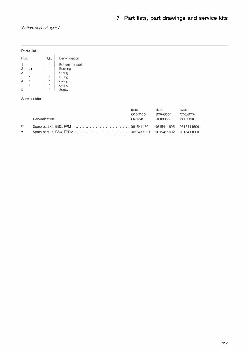
7 Part lists, part drawings and service kits
Bottom support, type 3
Parts list
Pos. Qty Denomination
1 1 Bottom support2 ♦ 1 Bushing3 1 O-ring
♦ 1 O-ring4 1 O-ring
♦ 1 O-ring5 1 Screw
Service kits
Denomination
size:Ø30/Ø35/Ø40Ø45
size:Ø50/Ø55/Ø60/Ø65
size:Ø70/Ø75/Ø80/Ø90
Spare part kit, BS3, FPM . . . . . . . . . . . . . . . . . . . . . . . . . . . . . . . . . . . . . . 9615411604 9615411605 9615411606♦ Spare part kit, BS3, EPDM . . . . . . . . . . . . . . . . . . . . . . . . . . . . . . . . . . . . 9615411601 9615411602 9615411603
117

7 Part lists, part drawings and service kits
Tools
7.15 Tools
To assist installation and maintenance of the Agitator, an original Alfa Laval Shaft Retainer is available. Once the bolts aretightened the shaft is retained by a well-defined torque leaving no doubt about safety. The amterial used protects the polishedsurface against scratching.
A very useful tool during maintenance of the Agitator.
Designed to support Agitator at a weight up to 500 kilogram.
Description Item no.Shaft diameter between Ø30 and Ø60 TE2608084880
TD605-039
TD605-173
Shaft retainer - mounting instructions:
WARNING
Ensure no personnel inside tank.
TD605-176
CAUTION
Ensure weight of Agitator is no higher than 500 kilogram.
TD605-177
Step 1Dismantle back plate by loosen both screws on the shaft retainer.
TD605-1741
2
1
118

7 Part lists, part drawings and service kits
Tools
Step 21. Dismantle Agitator from welding flange.2. Lift up Agitator.
TD605-075
1
2
Step 3Tighten both of the screws on the shaft retainer tool equal.
CAUTIONEnsure that the springs are completely compressed.
TD605-175
Retainer bolt and extractor bolt for bearing frame
Pos Denomination BC160D(H)/30 B25, B25/30 B35, B35/40 B45, B45/50 B55, B55/60Item no. Item no. Item no. Item no. Item no.
1 Retainer bolt TE2604036760 TE2604010700 TE2604010100 TE2604010890 TE26040109002 Extractor bolt TE2601000331 TE2601000331 TE2601000336 TE2601000334 TE2601000334
TD605-040
1
2
119

8 Appendix
8.1 Drive unit instructions
The drive unit is supplied by sub supplier and all important installation requirement is transferred to the agitator instructionmanual. For further information regarding maintenance and storage of the drive unit please find the drive unit instructionmanual by below links
For agitators with gears please find the drive unit instruction manual by below link:https://www.nord.com/cms/en/documentation/manuals/manuals.jspand select document "Gear Units and Geared Motor B1000".
For agitators with direct drive (motor only) please find the motor instruction manual by below link:http://www.hoyermotors.com/Catalogues-30304.htm
120

121

How to contact Alfa LavalContact details for all countries arecontinually updated on our website.Please visit www.alfalaval.com to access the information directly.
© Alfa Laval Corporate ABThis document and its contents is owned by Alfa Laval Corporate AB and protected by laws governing intellectual property and thereto related rights. It is the responsibility of the user of thisdocument to comply with all applicable intellectual property laws. Without limiting any rights related to this document, no part of this document may be copied, reproduced or transmitted in anyform or by any means (electronic, mechanical, photocopying, recording, or otherwise), or for any purpose, without the expressed permission of Alfa Laval Corporate AB. Alfa Laval Corporate ABwill enforce its rights related to this document to the fullest extent of the law, including the seeking of criminal prosecution.


