26
INSTRUCTION MANUAL INSTRUCTION MANUAL INSTRUCTION MANUAL INSTRUCTION MANUAL MODEL THN TENSION TRANSDUCERS DOC 801-1752

INSTRUCTION MANUALINSTRUCTION MANUALINSTRUCTION MANUALINSTRUCTION MANUALMODEL THN TENSION TRANSDUCERS
DOC 801-1752

217 Pickering Road
Rochester, NH 03867 U.S.A.
For assistance, please call:
TECHNICAL SERVICE - Installations, Start-Up, Troubleshooting, Repairs, Field Service, Returns.
CUSTOMER SERVICE - Replacement Parts, Individual Products, Questions about Orders, Manuals.
SALES - Product Information, Systems Application Questions,Placing orders for standard products and special systems.
Telephone: (603) 332-6150
Fax: (603) 332-3758
E-Mail : [email protected] Internet: www.dfe.com
©2004 Dover Flexo Electronics, Inc. All rights reserved. Dover Flexo Electronics has made reasonable effort to ensure accuracyof this document. However, NO WARRANTY, whether expressed or implied, is given regarding the completeness or correctnessof information in this document. Dover Flexo Electronics shall not be held liable for damages of any kind arising from the useof this document. Dover Flexo Electronics reserves the right to make changes, additions, and deletions to this document withoutnotice and without obligation.

i
TABLE OF CONTENTS
SECTION ONE DESCRIPTION PAGE1.1 General Description . . . . . . . . . . . . . . . . . . . . . . . . . . . . . . . . . . . 11.2 Construction and Mechanical Operation . . . . . . . . . . . . . . . . . . . . 11.3 Specifications . . . . . . . . . . . . . . . . . . . . . . . . . . . . . . . . . . . . . . . . . 21.4 Standard Features . . . . . . . . . . . . . . . . . . . . . . . . . . . . . . . . . . . . . 31.5 Configuration Choices . . . . . . . . . . . . . . . . . . . . . . . . . . . . . . . . . . 31.6 Options . . . . . . . . . . . . . . . . . . . . . . . . . . . . . . . . . . . . . . . . . . . . . . 3
SECTION TWO INSTALLATION2.1 Dimensions . . . . . . . . . . . . . . . . . . . . . . . . . . . . . . . . . . . . . . . . . . 42.2 Pre-Installation Requirements . . . . . . . . . . . . . . . . . . . . . . . . . . . . 42.3 Selection of Load Rating . . . . . . . . . . . . . . . . . . . . . . . . . . . . . . . . 62.4 Installation Instructions . . . . . . . . . . . . . . . . . . . . . . . . . . . . . . . . . 72.5 Removal of Roll and/or Transducers . . . . . . . . . . . . . . . . . . . . . . . 102.6 Electrical Operation . . . . . . . . . . . . . . . . . . . . . . . . . . . . . . . . . . . . 11
SECTION THREE CALIBRATION AND SET-UP3.1 Introduction . . . . . . . . . . . . . . . . . . . . . . . . . . . . . . . . . . . . . . . . . . . 123.2 Zero the Tension Meter . . . . . . . . . . . . . . . . . . . . . . . . . . . . . . . . . 123.3 Calibrate the Tension Meter . . . . . . . . . . . . . . . . . . . . . . . . . . . . . 12
SECTION FOUR CARE AND MAINTENANCE4.1 Bearing Life . . . . . . . . . . . . . . . . . . . . . . . . . . . . . . . . . . . . . . . . . . 13
SECTION FIVE TROUBLESHOOTING . . . . . . . . . . . . . . . . . . . . . . . . . . . . . . . . . 14
SECTION SIX REPLACEMENT PARTS . . . . . . . . . . . . . . . . . . . . . . . . . . . . . . . 16
APPENDICES: A. Transducer Electrical Connections . . . . . . . . . . . . . . . . . . . . . . 17B. Typical Tensions . . . . . . . . . . . . . . . . . . . . . . . . . . . . . . . . . . . . 18
Terms and Conditions . . . . . . . . . . . . . . . . . . . . . . . . . . . . . . . . . . 19Index . . . . . . . . . . . . . . . . . . . . . . . . . . . . . . . . . . . . . . . . . . . . . . . . 21
LIST OF ILLUSTRATIONS
FIGURE: 1. Model THN Cut-away View . . . . . . . . . . . . . . . . . . . . . . . . . . . . . . 22. Dimensions . . . . . . . . . . . . . . . . . . . . . . . . . . . . . . . . . . . . . . . . . . 43. Model THN Mounting Styles . . . . . . . . . . . . . . . . . . . . . . . . . . . . . 54. Tension Zones . . . . . . . . . . . . . . . . . . . . . . . . . . . . . . . . . . . . . . . . 55. Load Rating Selection formulas . . . . . . . . . . . . . . . . . . . . . . . . . . . 66. THN Load Rating Chart . . . . . . . . . . . . . . . . . . . . . . . . . . . . . . . . . 77. Shaft Length Calculation Formulas . . . . . . . . . . . . . . . . . . . . . . . . 78. Dead Shaft End Clearance . . . . . . . . . . . . . . . . . . . . . . . . . . . . . . 89. Live Shaft End Clearance . . . . . . . . . . . . . . . . . . . . . . . . . . . . . . . 9
10. Tension Force Direction . . . . . . . . . . . . . . . . . . . . . . . . . . . . . . . . . 911. Adjusting for Axial Play . . . . . . . . . . . . . . . . . . . . . . . . . . . . . . . . . 1012. Axial and Rotational Play . . . . . . . . . . . . . . . . . . . . . . . . . . . . . . . . 1013. Strain Gage Connections . . . . . . . . . . . . . . . . . . . . . . . . . . . . . . . . 1114. Web Path . . . . . . . . . . . . . . . . . . . . . . . . . . . . . . . . . . . . . . . . . . . . 1315. Model THN Transducer Wiring . . . . . . . . . . . . . . . . . . . . . . . . . . . 18

1
SECTION 1 PRODUCT DESCRIPTION
1.1 GENERAL DESCRIPTIONThe Model THN (thin) Tension Transducer is an electro-mechanical device that converts web tension into a dcvoltage which is proportional to tension. The voltage is amplified in external electronic circuitry and displayedon an analog or digital meter which is calibrated to indicate actual web tension. The tension reading is expressedin pounds, ounces, grams, kilograms, newtons or any other desirable units. It can also be supplied to a regulatorcircuit to control tension automatically.The narrow width of the THN transducer allows it to be installed in locations where other transducers will notfit. It has also been designed so that it is not necessary to remove the transducers from the machine whenremoving the idler roll. Installation is very easy because the transducers are installed on the machine framesfirst, and the idler roll is then installed in the transducers. A single bolt in the center of the transducer mounts itto the machine frame. Because only one bolt is used, the transducer can be oriented at any angle without theneed of multiple bolt patterns. The model THN can be used with both dead shaft and live shaft idler rolls, with a variety of shaft sizes.The information in this section will help give a clear understanding of the Model THN Transducer, how it worksand how it is used.
1.2 CONSTRUCTION AND MECHANICAL OPERATION (see Figure 1)In a typical installation, a transducer is mounted on each end of a standard idler roll. The roll shaft may bestationary (non-rotating or dead) in which case the transducer is known as the dead-shaft, or D version. Or theroll shaft may be rotating (live) and the transducer is known as the live-shaft, or L version. Both versions have aremovable cap that clamps the shaft and allows removal of the idler roll from the transducers without removingthe transducers from the machine. The L version is the same as the D version except, instead of clamping theshaft, the cap clamps a bearing which is installed on the end of the roll shaft. The transducer contains a universal joint which allows the THN to compensate for misalignment and deflectionof the idler roll shaft. This compensation is extremely important because it prevents mechanical pre-loading ofthe transducer which causes inaccurate tension measurement and may damage the transducer. A small amountof axial movement is built into the transducer to compensate for variations in shaft length caused by temperaturefluctuations and shaft bending.Inside the transducer is a dual cantilever beam with long-life semiconductor strain gages mounted on the topbeam surface. The shaft is attached to the free end of the beam. When web tension is applied the beam deflectsa small amount, causing an electrical output from the strain gages.A mechanical stop prevents damage from accidental overloads. The stop is functional through 360 degrees, sothe overload condition may occur from any direction, not just the load direction. In all cases, the beam isprevented from deflecting far enough to cause any damage.

2
Figure 1 - MODEL THN CUT-AWAY VIEW
1.3 SPECIFICATIONSExcitation Voltage: . . . . . . . . . . . . . . . 5 Volts dcOutput: . . . . . . . . . . . . . . . 250 mV, nominal, at 5V excitationStrain Gages: . . . . . . . . . . . . . . . semiconductor, 100 ohms +/- 15 resistanceRepeatability: . . . . . . . . . . . . . . . +/- 1/4% full span (FS)Linearity and Hysteresis Combined: . . . +/- 1/2% FSTemperature Range: . . . . . . . . . . . . . . . -10° F to +200° F (-23° C to +93° C)Temperature Coefficient: . . . . . . . . . . . . . 0.02% per degree F, typical (0.01% per degree C, typical)Material: . . . . . . . . . . . . . . . 303 stainless steel and 7075-T6 aluminumMinimum Overload Capacity: . . . . . . . . 2500 lbs. (11121 N)Deflection: . . . . . . . . . . . . . . . 0.005" typical (0,127 mm typical)Mis-alignment Capacity (degrees) . . . . . 2°Mating Electrical Connector: . . . . . . . . . Amphenol MS3106A-10SL-3SStandard Connector Position: . . . . . . . . . 1:30 o'clock with reference to force direction at 6 o’clockElectrical Connections: . . . . . . . . . . . . . pin A - white wire = output
pin B - black wire = +5V pin C - red wire = -5V
Maximum Shaft Sizes: . . . . . . . . . . . . . Dead (D) = 1.65" (42 mm), Live (L) = 0.98" (25 mm) Shaft Size Tolerance: . . . . . . . . . . . . . . . nominal -0.002" (-0,051 mm) for D versionLoad Ratings: . . . . . . . . . . . . . . . . . . . . 25, 50, 100, 200, 400, 800 lbs. (110, 225, 450, 900, 1800, 3550 N)Mounting Bolt: . . . . . . . . . . . . . . . 3/8-16 Low Head socket cap screw (M10 Low Head socket cap
screw is optional)

3
1.4 STANDARD FEATURES• Only 1.76" (44.7mm) thick. Fits where most transducers can not.• One-bolt installation. Turn the transducer to the correct load orientation and tighten only one bolt.• Shaft clamp. Allows quick removal of idler roll without removing transducers from machine.• Dual Cantilever Beam. Provides high strength and accuracy at low tension.• Stainless Steel and Aluminum construction. Excellent corrosion resistance.• Universal joint. Corrects for misalignment and shaft bending.• Axial Movement. For changes of shaft length caused by temperature variations. • Both dead shaft and live shaft versions. Accommodates either stationary or rotating idler roll shafts.
1.5 CONFIGURATION CHOICES
These are explanations of standard choices of various configurations that were specified for your application.• Version Style. L (Live) for rotating shafts, or D (Dead) for stationary or non-rotating shafts.• Mounting Style. Screw or Bolt mount (S) uses a single bolt to mount flat against machine frame. The bolt
must have a “low head” to avoid interference with the idler roll shaft. The THN transducer can also be installed very precisely by using a shallow pilot hole in the machine frame.
• Load Ratings. 25, 50, 100, 200, 400, 800 lbs. (110, 225, 450, 900, 1800, 3550 N)• Bore/Shaft Size. Choices are as follows:
D Version: 3/4, 7/8, 1, 1 1/8, 1 3/16, 1 1/4, 1 1/2, inches, 25mm, 30mmL Version: 20mm, 25mm Note: Cannot exceed maximum size listed in Specifications in section 1.3.
• Connector Position. 1:30 o’clock with tension force direction at 6 o’clock
1.6 OPTIONS• Environmental Connector (EC). Seals with mating cable electrical connector to protect against contact
oxidation; especially useful in corrosive environments.• Extended Range (XR). Produces twice the output signal for a given load rating. Used in applications
requiring a full scale tension force that is as low as 6% of the transducer rating.- 12% is standard. Must beused with electronics having the XRE, extended range option.
• Full Bridge (FB). Four strain gauges instead of two to form a Wheatstone Bridge connection. Applies onlyif one transducer is used.
• Metric Mounting Stud (MMS). Metric screw for installation. Must have low head.• Vacuum Compensation (VAC). Transducer has special screws and features for fast and complete air
evacuation. Used for transducers installed in vacuum metallizers.

4
SECTION 2 INSTALLATION
2.1 DIMENSIONS inches (mm)
Figure 2 - THN DIMENSIONS
2.2 PRE-INSTALLATION REQUIREMENTSA. TRANSDUCER ROLL
The Model THN Transducers are used in pairs. One is mounted at each end of an idler roll shaft. The rollchosen is called the Transducer Roll.1. The Transducer Roll MUST be a true idler! It can NOT be a driven roll! There can be NO brakes,
clutches, belts, chains or gears attached to it or its shaft. It can not be a nip roll or be in contact with a niproll. It can not be filled with water or have pipes or hoses attached to it. Nothing must contact the rollor its shaft except the web!
2. The Transducer Roll shaft may be non-rotating (use the D version transducer) or rotating (use the Lversion transducer). If the shaft rotates, it must be designed and built for rotating service. Usually thismeans that it is straight, dynamically balanced and strong enough to resist bending from web tensionforces.
3. The roll must be Dynamically Balanced if web speed is over 300 FPM! Refer to Section 2.4.B forspecifications. An unbalanced roll will reduce the accuracy of the tension signal and may DAMAGE thetransducers.

5
B. WRAP ANGLE The web must always contact the transducer roll in exactly the same way. The wrap angle must not change asthe unwind or rewind roll diameter changes. Therefore there must be at least one idler roll between thetransducer roll and the unwind or rewind shaft. If the machine has more than one webbing path, be sure tochoose a roll that is wrapped the same for each. Otherwise it will be necessary to install an additional pair oftransducers, or dual calibration circuitry, or both. If the wrap angle is allowed to change, the transduceroutput will change with angle as well as tension, and accuracy will be reduced. Minimum wrap angle of 20°is required in most cases.
C. MOUNTING SURFACEThe structure on which the transducers are mounted MUST be very stable and strong. Any movement of thestructure may be sensed by the transducers and may cause inaccurate tension readings. The surfaces mustalso be smooth and flat so the transducers won't be misaligned when they are installed.
Figure 3 - MODEL THN MOUNTING STYLESD. TENSION ZONE
The roll must be located in the tension zone which is to be monitored or controlled. The beginning or end ofany tension zone is always at a nip (driven or braked), unwind shaft, rewind shaft or drag bar. Any element inthe web path that can change web tension is at one end of a tension zone.
Figure 4 - TENSION ZONES

6
2.3 SELECTION OF LOAD RATINGA. LOAD RATINGS
The Model THN Transducer is available in several standard load ratings, ranging from 25 lbs. to 800 lbs. The correct rating for any particular application depends on web tension, transducer roll weight, wrap angle,and the direction of the tension force on the transducer roll. Figure 5 below contains mathematical formulaswhich use these factors to determine the correct load rating.
B. SELECTION PROCEDURE The correct load rating is found in four simple steps:1. OBTAIN DATA TO PLUG INTO THE SELECTION FORMULA
a. Weigh the transducer roll.b. Estimate the maximum web tension. Use the Typical Tensions table in Appendix B as a guide if
necessary.c. Determine the wrap angle.d. Determine the angle of the tension force, FT, relative to the vertical. (NOTE: FT bisects the wrap angle
B)2. COMPUTE NET FORCE USING THE SELECTION FORMULA
Refer to Figure 5. Select the appropriate wrap configuration as determined by the direction of the tensionforce (above, below or on horizontal). Compute the Net Force, using the formula below the wrapdiagram.
Figure 5 - LOAD RATING SELECTION FORMULAS
Use Figure 6 to select the correct load rating. In some cases, the load rating may be LESS than thecomputed Net Force. This is acceptable because the Net Force formula contains an oversizing factor of 2for tension surges, which means that the actual force exerted on the transducer will not exceed its rating ifthe transducer is chosen according to the chart below. The actual force on the transducer will reach 125%of the load rating before hitting the beam deflection stop.

7
3. SELECT THE LOAD RATING
LOAD RATING CHARTNET FORCE (lb) LOAD RATING (lb)
up to 32 2533 - 63 50
64 - 125 100126 - 187 150126 - 250 200251 - 500 400
501 - 1000 800
Figure 6 - LOAD RATING CHART
4. COMPARE LOAD RATING WITH EFFECTIVE TRANSDUCER ROLL WEIGHTSometimes, a transducer roll is so heavy that its weight uses up most of the operating range of thetransducers. When this happens, it may not be possible to adjust the tension indicating meter to read zerowhen tension is zero because the adjustment range of the electronic circuit has been exceeded. To findout if the roll is too heavy, compare the load rating with the effective weight of the roll as follows:Refer back to the Net Force formula used in Section 2.3.B.2. The effective roll weight on the pair oftransducers is the "W Cos(A)" term in the formula. If W Cos(A) is more than 95% of the load ratingchosen, the tension meter will probably not be adjustable to zero. If this is the case, one or more of thefollowing changes must be made to reduce W Cos(A) to less than 95% of the load rating:1. Reduce the transducer roll weight.2. Increase angle (A). (See Figure 5).3. Use the next higher load rating. (This is the least desirable choice because it reduces the output
signal).
2.4 INSTALLATION INSTRUCTIONSModel THN Transducers are very easy to install. For both the Dead Shaft (D) version and Live Shaft (L) version,both transducers are mounted on the machine and the roll is then installed in them.A. DETERMINE SHAFT LENGTH
Measure the distance between the machine frames (D) where the transducers will be mounted. Use theappropriate formula below to determine the correct shaft length. The formulas allow approximately 1/16 inch(1.5mm) clearance at both shaft ends. This clearance is necessary for proper operation and for ease ofinstallation and removal. DO NOT ALLOW THE SHAFT TO CONTACT THE BOTTOM OF THE BORE. This may cause pre-loading! (see Figure 8).
SHAFT LENGTH CALCULATIONSIZE FLUSH MOUNT PILOT MOUNT
2 L = D - 2.04 in (52 mm) L = D - 1.92 in (49mm)L = Shaft length in inches D = Distance between mounting surfaces in inches
Figure 7 - SHAFT LENGTH CALCULATION FORMULA

8
B. BALANCE THE ROLLThe roll must be dynamically balanced if web speed is 300 FPM or more. Balance the roll to Quality GradeG-2.5 as described in ISO 1940 and ANSI S2.19-75 standards. If these standards are not available, pleasecontact Dover Flexo Electronics and we will provide the appropriate data.
C. INSTALL THE ROLL AND TRANSDUCERS ON THE MACHINEThis part of the installation is slightly different for the (D) and (L) versions. Use the procedure under 1.below for the (D) version. Use the procedure under 2. for the (L) version. However, refer to Figures 8 and 9for each version for illustration of the shaft end clearance. CAUTION! To avoid injury, be sure to follow yourapproved lockdown/lockout procedure before removing or installing rolls.1. Installation Procedure for the D (dead shaft) Version:
a. Ensure that your shaft ends for the bushing size for your transducers. Refer to Figure 8.b. Remove the clamp from the transducer by removing the two cap screws. Mount the transducers on the
machine using the mounting bolt provided. Bring the bolt through the transducer front, through thepiloted mounting flange and into the tapped inside wall of the machine frame. Orient the transducer sothe force direction arrow bisects the wrap angle. The arrow must point away from the web contact areaon the roll. Refer to Figure 10. Tighten the mounting bolt.
c. Lift and set the roll in place and hold it there.d. Install the clamps and screws on both transducers. Leave the screws slightly loose.e. Adjust the shaft depth to allow approximately 1/16 inch (1.5mm) end clearance in ONE transducer
ONLY (see Figure 8). Tighten the clamp screws to fasten the shaft into the transducer.DO NOT TIGHTEN the clamp screws on the other transducer yet! This must be done later, in Step D.
Figure 8 - DEAD SHAFT END CLEARANCE
2. Installation Procedure for the L (Live shaft) version:a. Ensure that roll ends are stepped or include snap ring to match dimensions(show below in Figure 9)
for the correct bearing inner diameter and depth.b. Install the bearings on the ends of the idler roll shaft.c. Follow steps b thru e in 2.4.C.1. above.d. Tighten clamp bolts to not more than 5 lb-ft torque.

9
DESIGNATOR ØA ØB C
20MMBORE
BEARING
INCH0.78800.7875
1.062 0.512
mm 20.01520.002
27 13
25MMBORE
BEARING
INCH0.98480.9843
1.062 0.394
mm25.01525.002
27 10
Figure 9 - DEAD SHAFT END CLEARANCE
Figure 10 - TENSION FORCE DIRECTION
D. TIGHTEN THE LOOSE TRANSDUCER CLAMP (follow the instructions below very carefully)For any tension transducer to operate properly, there must be some axial (along the idler shaft) movementcapability to allow for shaft deflection and length variations caused by temperature fluctuations. The ModelTHN transducer is designed with approximately 0.040 inches (1.0mm) of axial movement per transducer witha maximum of 0.080" (1.5mm) per pair. To preserve this capability, follow the instructions below. A normalinstallation will have about 0.040" (1.0 mm) of axial movement. The D version coupling should also have asmall amount of rotational free play. See Figure 12.1. Procedure Refer to Figure 11. Remember, the left end transducer is tightly clamped to the shaft and the
right end transducer clamp is loose.a. Pull the roll toward the loose clamp on the right end while pushing this transducer away from the roll.

10
b. Rotate the shaft and the loose transducer a small amount by hand in the same direction until they bothstop.
c. Tighten the clamp cap screws alternately and progressively ½ turn at time to clamp the shaft into thetransducer. NOTE: Do not exceed 5 lb-ft torque for L (live shaft version). Higher torque createsdrag.
d. If shaft length is correct and installation has been done correctly, you will be able to move the idlerroll shaft axially at least 0.040 inch (1.0mm). THE AXIAL MOVEMENT IS ESSENTIAL TO THEPROPER OPERATION OF THE TRANSDUCERS! If no movement can be detected, loosen one shaftcoupling and repeat the installation procedures, Section 2.4.C, 1 or 2.
Figure 11 - ADJUSTING FOR AXIAL PLAY2. Special procedure for Hot Installations: If the idler roll is exposed to high temperatures (from a hot
web, for example), it may be advisable to maximize the axial movement to allow the shaft length toexpand more without danger of preloading the transducers. To increase axial movement to the maximum;follow the procedures in 2.4.D, BUT push the loose transducer toward the roll instead of away from it.Refer to Figure 10. This will double the available axial expansion capability as compared to the normalinstallation procedures.VERIFY THE AXIAL MOVEMENT NOW. NOTE: If you used the special procedure for hot installationsyou will not be able to measure any axial movement until the idler roll gets hot.

11
Figure 12 - AXIAL AND ROTATIONAL PLAYVERIFY THE ROTATIONAL FREE PLAY (D version, only) at this time, see Figure 11. Not much is needed,only enough to be able to feel. If none is detected, loosen one shaft clamp and turn both the idler shaft and theloose coupling in the SAME direction. Then re-tighten the clamp.The rotational and axial movements eliminate the possibility of mechanically pre-loading the transducers. Pre-loading causes non-linearity, zero-drift, and loss of calibration.NOTE: It is important for accuracy and safety that the shaft clamp screws be tightened firmly.
E. CHECK THE GAP FOR CORRECT ALIGNMENT (see Figure 12)Up to 2° of transducer misalignment is possible. However, misalignment during installation may causemechanical preloading and loss of accuracy. It is best to minimize misalignment as much as possible.Measure the gap between the transducer and machine frame in at least four places equally spaced around thecircumference of each transducer. A mis-alignment of 2° will measure 0.096" (2.4mm) difference inclearance between the transducer and the machine frame from the minimum gap to the maximum gap. Shimor reposition the transducers at the mount surface as necessary. If shims are installed, check the axialmovement again. Refer to 2.4D.1 or 2 for the procedure. Be sure the correct axial movement is present.
2.5 REMOVAL OF ROLL AND/OR TRANSDUCERSTo remove the transducers, first support the idler roll so it won't fall. Then, follow the procedure below toremove the roll shaft from the transducers. CAUTION! To avoid injury, be sure to follow your approvedlockdown/lockout procedure before removing or installing rolls.A. Procedure for both D and L versions:
1. Remove the two screws from the shaft clamp on each transducer and lift off the clamp.2. Take the roll out of the transducers.3. Remove transducers, if needed.
2.6 ELECTRICAL OPERATIONThe Model THN Transducer is used in pairs, one on each end of an idler roll shaft. Web tension exerts a forceon the roll which is transmitted to the cantilever beam by the idler roll shaft. Two semiconductor strain gages aremounted on the beam, one on the top and one on the bottom. As force is applied and the beam deflects, the topgage is stretched and the bottom gage is compressed. This increases the electrical resistance of the top gage anddecreases the resistance of the bottom gage. The gages in both transducers are electrically connected together ina Wheatstone bridge configuration. The output from the bridge is the sum of the output from the two transducers.Therefore, web position, width and loose or tight edges do not affect the accuracy of the tension signal.

12
Figure 13 - STRAIN GAGE CONNECTIONS
The physical location of the strain gages, on opposite ends of the beam, ensures that each gage experiences thesame temperature variations. This, and the Wheatstone bridge configuration, provides automatic temperaturecompensation and a stable output.The strain gages are high output semiconductor devices which typically have an output sixteen times greater thanthe inexpensive foil gages used in some transducers. Therefore, the signal amplifier used with these Model THNtransducers is a very stable low-gain design. An added benefit of the high output is inherently high immunity toelectrical noise.

13
SECTION 3 CALIBRATION AND SETUP
3.1 INTRODUCTIONThere are no calibration adjustments on the Model THN transducer itself. The instructions below are for theelectronic device which the transducers are connected to. All of the terminology and procedures, following,assume that the transducers are connected to a DOVER FLEXO ELECTRONICS tension controller or tensionindicator. If some other device is being used, you should follow the instructions furnished with it.These are general instructions which are correct for most DFE controllers and indicators, and are placed here foryour convenience. If you have any difficulty calibrating or if there is any discrepancy between these instructionsand those in the Instruction Manual for the indicator or controller, you should disregard these instructions andfollow the instructions in the Manual for the indicator or controller.The transducers must be properly installed and oriented as directed in SECTION 2.4, pages 7-10.
3.2 ZERO THE TENSION METER1. Turn the "POWER" switch off. If the meter does not read zero, turn the mechanical adjustment screw on the
meter face so the needle indicates zero tension.2. Find an object of some kind that weighs at least 25% of the maximum value on the tension meter scale. (Be
sure you know the exact weight). Calculate the exact ratio of this calibration weight and the expected webtension.
3. Find a rope, tape, or wire that will support the weight in 2. above.4. Verify that there is no web contacting the Transducer Roll. Turn the "POWER" switch on. Wait for about
five minutes for the tension meter to settle. Turn the "CALIBRATE" pot. to approximately 75%. Then, turnthe "ZERO" pot. so the tension meter reads zero tension.
3.3 CALIBRATE THE TENSION METERSee Figure 13. Pass the rope over the Transducer Roll in exactly the same path as the web follows. Tie the endin the machine at least one idler roll beyond the Transducer Roll. Pass the other end by at least one idler rollbefore the Transducer Roll. Be sure the rope does not pass over any driven rolls, braked rolls, or dead bars. (This will cause in-accurate calibration). Attach the weight to the free end of the rope and let it hang withouttouching anything. Turn the "CALIBRATE" pot. so the tension meter reads the same ratio of scale as the ratioof the calibration weight and maximum tension calculated in Section 3.2. Remove the weight and rope. Thisconcludes the calibration procedure.
Figure 14 - WEB PATH

14
SECTION 4 CARE AND MAINTENANCE
Your Dover Flexo Model THN Tension Transducers have been manufactured of quality materials. With properapplication and installation your transducers will be maintenance free and long lasting. Any changes in yourapplication which affect the dynamics of your equipment such as web speed, net force, material, etc. couldpossibly require upgrading of load rating or a roll change. Contact Dover for specific information andengineering assistance.
4.1 BEARING LIFE (L version, only)The shaft bearing in the L (live or rotating shaft) version of the Model THN transducer will turn continuously innormal operation. It has been selected to give a long service life under typical operating conditions and islubricated for life. Be sure the bearing clamp screws have been tightened to no more than 5 lb-ft torque.Higher torque will deform the bearing and shorten its life. It will also cause the idler roll to resist turning,creating drag.

15
SECTION 5 TROUBLESHOOTING
This is a list of problems which could occur during initial start-up or afterwards. The probable causes are listedwith the most likely one first and the least likely one last.
1. TRANSDUCER ROLL SHAKES, VIBRATES, or BOUNCESa. Roll is not balanced. See Section 2.4.B page 8 and Section 2.2 page 4.b. Shaft is not clamped tightly in transducers. Coupling screws are loose or shaft diameter is undersize.c. Transducer mounting bolts are not tight.d. Shaft is too weak or there is too much shaft extension between the ends of the roll and the transducers.e. Shaft is bent or too weak.f. Roll is turning at its natural frequency. Call our TECHNICAL SERVICE DEPARTMENT for analysis of
operating conditions and solution to problem.
2. CAN NOT ADJUST TENSION METER TO READ ZERO WHEN WEB IS SLACKa. Transducer roll is too heavy. See Section 2.3.B.4 on page 7.b. Transducers are pre-loaded. See Section 2.4.A page 7 and 2.4.D page 9.
3. TENSION METER READS BACKWARDSa. Transducers are installed backwards with force arrow pointing in opposite direction. See Section 2.4.C
page 8.b. Transducer cables are connected wrong at controller/indicator terminal strip. Signal wires are reversed.
4. TENSION METER NEEDLE PEGS HIGH OR LOWa. Meter is not electrically adjusted to zero. See Section 3.2 page 12. b. Transducers are pre-loaded. See Section 2.4.A page 7 and 2.4.D page 9.c. Transducer cable has broken wire, poor connection or short circuit.d. A strain gage has failed. To verify: Unplug the transducer cable and use an ohm-meter to measure the
resistance of the gages at the connector on the transducer. Measure between pins A,B, and A,C. In eachcase, the resistance should be about 100 ohms. Measure the resistance between any pin and the outside ofthe transducer. The meter should read infinite resistance. Apply a force to the roll by hand or by using arope and a weight, in the direction of the tension force and maintain it while again measuring betweenpins A,B and A,C. The resistance should be only a few ohms different from before.
e. Failure in the tension amplifier circuit of the controller/indicator.
5. TENSION METER DOES NOT READ ZERO WHEN WEB IS SLACK AND READING DRIFTS WITH TIME.a. Meter is not calibrated. See Section 3.3 page 12b. Transducers are pre-loaded. See Section 2.4.A page 7 and 2.4.D page 9.c. The structure the transducers are mounted on is weak. See Section 2.2.C page 5.d. Transducer cable has a broken wire, poor connection or short circuit.e. A strain gage is cracked. Perform the test in 4d above.

16
6. TENSION METER DOES NOT READ THE SAME EACH TIME THE SAME FORCE IS APPLIED (poorrepeatability)a. Transducers are pre-loaded. See Section 2.4.A page 7 and 2.4.D page 9.b. The structure the transducers are mounted on is weak. See Section 2.2.C page 5.c. The shaft coupling cap screws are loose.
7. TENSION METER READING DOES NOT CHANGE WHEN FORCE IS APPLIED TO ROLL. METERREADS ZERO.a. Meter is not calibrated. See Section 3.3 page 12.b. Gap between shaft coupling and beam housing is not even. See Section 2.4.E page 10.c. Transducer roll is too heavy. See Section 2.3.B.4, page 7.d. Transducer cable has broken wire, poor connection or short circuit.e. Transducer cables connected incorrectly, or to wrong transducers.f. Failure of tension amplifier circuit in controller/indicator. Unit not turned on.
8. TENSION METER NEEDLE BOUNCESa. Web tension is fluctuating because of machine speed fluctuations, bent roll shafts, worn idler roll
bearings, chattering unwind brake, flat spot in unwind or rewind roll, etc.b. Shaft is loose in the transducers. Shaft coupling cap screws are loose or shaft diameter is under-size.c. Transducer mounting bolts are loose.d. Tension controller is not adjusted properly. See controller Instruction Manual for procedure.
9. TRANSDUCER ROLL WON”T TURN FREELY (Live shaft version, L, only) a. Clamp screws too tight. Loosen and retighten to no more than 5 lb-ft torque. The bearing on the idler roll
shaft is squeezed too tightly.

17
SECTION 6 REPLACEMENT PARTS
PART TRADE NUMBER DOVER PART NUMBER
Electrical Connector MS3102A - 10SL - 3P 106-0070
Connector Screws M3 x 6 Socket Button Head 123-0032
Joint Bearing 1204 133-0058
Shaft Bearing (L type only)20mm
6004 2Z 133-0061
Shaft Bearing (L type only)25mm
61905 133-0062
Shaft Bushing (D Type) None 866-1750 (Specify bore diameter)
Shaft Clamp Screws (D & L Type)
M8 x 20 123-0045
Mounting Bolt 3/8 - 16 Low Head socket cap screwM10 Low Head socket cap screw
(option)
123-0464123-0462
NOTE: All screws are steel socket head, metric, grade 8.8 or higher, coarse thread unless otherwise noted.
Call Customer Service for prices and for part numbers of items not listed. For helpwith service or repairs, call Technical Service.
DOVER FLEXO ELECTRONICSTelephone: 603-332-6150
Fax: 603-332-3758TOOLS NEEDED FOR DISASSEMBLYThe following metric socket screw keys are the only tools normally needed for assembly or disassembly of theModel THN transducer.
Screw Size Key Size (mm) Transducer SizeM3 button/flat heads 2.0 2
M3 2.5 2M5 4.0 2M6 5.0 2M8 6.0 2

18
Appendix A: Transducer Electrical Connections
Figure 15 - MODEL THN TRANSDUCER WIRING
19
Appendix B: Typical Tensions for Various Materials
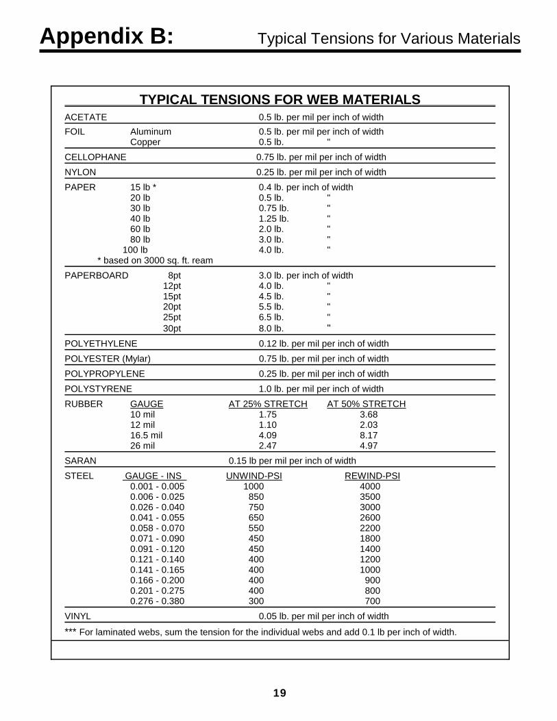
TYPICAL TENSIONS FOR WEB MATERIALSACETATE 0.5 lb. per mil per inch of widthFOIL Aluminum 0.5 lb. per mil per inch of width
Copper 0.5 lb. "CELLOPHANE 0.75 lb. per mil per inch of widthNYLON 0.25 lb. per mil per inch of widthPAPER 15 lb * 0.4 lb. per inch of width
20 lb 0.5 lb. " 30 lb 0.75 lb. "40 lb 1.25 lb. "60 lb 2.0 lb. "80 lb 3.0 lb. "
100 lb 4.0 lb. "* based on 3000 sq. ft. ream
PAPERBOARD 8pt 3.0 lb. per inch of width12pt 4.0 lb. "15pt 4.5 lb. "20pt 5.5 lb. "25pt 6.5 lb. "30pt 8.0 lb. "
POLYETHYLENE 0.12 lb. per mil per inch of widthPOLYESTER (Mylar) 0.75 lb. per mil per inch of widthPOLYPROPYLENE 0.25 lb. per mil per inch of widthPOLYSTYRENE 1.0 lb. per mil per inch of widthRUBBER GAUGE AT 25% STRETCH AT 50% STRETCH
10 mil 1.75 3.6812 mil 1.10 2.0316.5 mil 4.09 8.1726 mil 2.47 4.97
SARAN 0.15 lb per mil per inch of widthSTEEL GAUGE - INS UNWIND-PSI REWIND-PSI
0.001 - 0.005 1000 40000.006 - 0.025 850 35000.026 - 0.040 750 30000.041 - 0.055 650 26000.058 - 0.070 550 22000.071 - 0.090 450 18000.091 - 0.120 450 14000.121 - 0.140 400 12000.141 - 0.165 400 10000.166 - 0.200 400 9000.201 - 0.275 400 8000.276 - 0.380 300 700
VINYL 0.05 lb. per mil per inch of width
*** For laminated webs, sum the tension for the individual webs and add 0.1 lb per inch of width.

20
TERMS AND CONDITIONS OF SALE AND SHIPMENT1. THE COMPANY 5/1/00Dover Flexo Electronics, Inc. is hereinafter referred to as the Company.
2. CONFLICTING OR MODIFYING TERMS No modification of, additions to or conflicting provisions to theseterms and conditions of sale and shipment, whether oral orwritten, incorporated into Buyer's order or other communicationsare binding upon the Company unless specifically agreed to bythe Company in writing and signed by an officer of the Company.Failure of the Company to object to such additions, conflicts ormodifications shall not be construed as a waiver of these termsand conditions nor an acceptance of any such provisions.
3. GOVERNING LAWThis contract shall be governed by and construed according tothe laws of the state of New Hampshire, U.S.A. The parties agreethat any and all legal proceedings pursuant to this contract shalltake place under the jurisdiction of the courts of the State of NewHampshire in the judicial district of Strafford County.
4. PENALTY CLAUSESPenalty clauses of any kind contained in orders, agreements orany other type of communication are not binding on the Companyunless agreed to by an officer of the Company in writing.
5. WARRANTYDover Flexo Electronics, Inc. warrants its' products to be free ofdefects in material and workmanship for five years from date oforiginal shipment. Warranty is valid on products purchased on orafter April 2, 1999. During the warranty period the Company willrepair or replace defective products free of charge if suchproducts are returned with all shipping charges prepaid and if,upon examination, the product is shown to be defective. Thiswarranty shall not apply to products damaged by abuse, neglect,accident, modification, alteration or mis-use. Normal wear is notwarrantied. All repairs and replacements under the provisions ofthis warranty shall be made at Dover Flexo Electronics or at anauthorized repair facility. The Company shall not be liable forexpenses incurred to repair or replace defective products at anyother location or by unauthorized persons or agents. Thiswarranty contains all of the obligations and warranties of theCompany. There are no other warranties, either expressed orimplied. No warranty is given regarding merchantability orsuitability for any particular purpose. The Company shall not beliable in either equity or law for consequential damages, losses orexpenses incurred by use of or inability to use its' products or forclaims arising from same. No warranty is given for products ofother manufacturers even though the Company may providethese products with its' own or by themselves. The provisions ofthis warranty can not be changed in any way by any agent oremployee of the Company. Notice of defects must be receivedwithin the warranty period or the warranty is void.
6. PAYMENTSStandard terms of credit are net 30 days from date of shipment,providing satisfactory credit is established with the Company.Amounts past due are subject to a service charge of 1.5% permonth or portion thereof or 18% per annum. The Companyreserves the right to submit any unpaid late invoices to a thirdparty for collection and Buyer shall pay all reasonable costs ofsuch collection in addition to the invoice amount. All quoted pricesand payments shall be in U.S. Dollars.If the Company judges that the financial condition or paymentpractices of the Buyer does not justify shipment under thestandard terms or the terms originally specified, the Companymay require full or partial payment in advance or upon delivery.The Company reserves the right to make collection on any termsapproved in writing by the Company's Finance Department. Eachshipment shall be considered a separate and independent
transaction and payment therefore shall be made accordingly. Ifthe work covered by the purchase order is delayed by the Buyer,upon demand by Company payments shall be made on thepurchase price based upon percentage of completion.
7. TAXESAny tax, duty, custom, fee or any other charge of any naturewhatsoever imposed by any governmental authority on ormeasured by any transaction between the Company and theBuyer shall be paid by the Buyer in addition to the prices quotedor invoiced.
8. RETURNSWritten authorization must be obtained from the Company'sfactory before returning any material for which the Buyer expectscredit, exchange, or repairs under the Warranty. Returnedmaterial (except exchanges or repairs under the Warranty) shallbe subject to a minimum re-stocking charge of 15%. Non-standard material or other material provided specially to the Buy-er's specification shall not be returnable for any reason. Allmaterial returned, for whatever reason, shall be sent with allfreight charges prepaid by the Buyer.
9. SHIPPING METHOD AND CHARGESAll prices quoted are F.O.B. the Company's factory. TheCompany shall select the freight carrier, method and routing.Shipping charges are prepaid and added to the invoice of Buyerswith approved credit, however the Company reserves the right toship freight-collect if it prefers. Shipping charges will include acharge for packaging. Company will pay standard ground freightcharges for items being returned to Buyer which are repaired orreplaced under the Warranty.
10. CANCELLATION, CHANGES, RESCHEDULINGBuyer shall reimburse Company for costs incurred for any item onorder with the Company which is cancelled by the Buyer. Costsshall be determined by common and accepted accounting prac-tices. A one-time hold on any item ordered from the Company shall beallowed for a maximum of 30 days. After 30 days, or upon noticeof a second hold, Company shall have the right to cancel theorder and issue the appropriate cancellation charges which shallbe paid by Buyer. Items held for the Buyer shall be at the risk andexpense of the Buyer unless otherwise agreed upon in writing.Company reserves the right to dispose of cancelled material as itsees fit without any obligation to Buyer.If Buyer makes, or causes to make, any change to an order theCompany reserves the right to change the price accordingly.
11. PRICESPrices published in price lists, catalogs or elsewhere are subjectto change without notice and without obligation. Written quotedprices are valid for thirty days only.
12. EXPORT SHIPMENTSPayment for shipments to countries other than the U.S.A. andCanada or to authorized distributors shall be secured by cash inadvance or an irrevocable credit instrument approved by anofficer of the Company. An additional charge of 10% will apply toany letter of credit. There will be an extra charge for packagingand documentation.
13. CONDITION OF EQUIPMENTBuyer shall keep products in good repair and shall be responsiblefor same until the full purchase price has been paid.
14. OWNERSHIPProducts sold are to remain the property of the Company until fullpayment of the purchase price is made.

21
NOTES
22
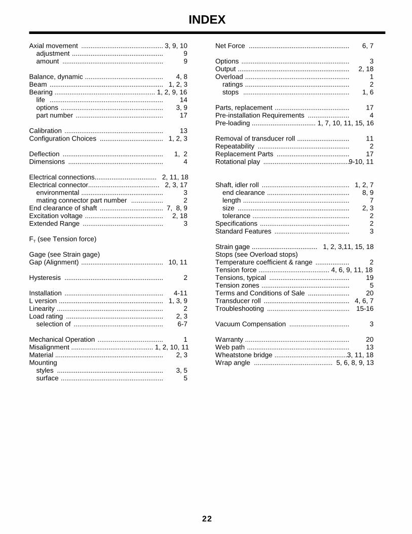
INDEX
Axial movement ............................................ 3, 9, 10adjustment ................................................. 9amount ...................................................... 9
Balance, dynamic .......................................... 4, 8Beam ............................................................. 1, 2, 3Bearing ...................................................... 1, 2, 9, 16
life ............................................................. 14options ....................................................... 3, 9part number ............................................... 17
Calibration ..................................................... 13Configuration Choices .................................. 1, 2, 3
Deflection ...................................................... 1, 2Dimensions ................................................... 4
Electrical connections................................. 2, 11, 18Electrical connector...................................... 2, 3, 17
environmental ............................................ 3mating connector part number ................. 2
End clearance of shaft .................................. 7, 8, 9Excitation voltage .......................................... 2, 18Extended Range ........................................... 3
FT (see Tension force)
Gage (see Strain gage)Gap (Alignment) ............................................ 10, 11
Hysteresis ..................................................... 2
Installation ..................................................... 4-11L version ........................................................ 1, 3, 9Linearity ......................................................... 2Load rating .................................................... 2, 3
selection of ................................................ 6-7
Mechanical Operation ................................... 1Misalignment ............................................ 1, 2, 10, 11Material .......................................................... 2, 3Mounting
styles ......................................................... 3, 5surface ....................................................... 5
Net Force ...................................................... 6, 7
Options .......................................................... 3Output ............................................................ 2, 18Overload ........................................................ 1
ratings ........................................................ 2stops ......................................................... 1, 6
Parts, replacement ........................................ 17Pre-installation Requirements ...................... 4Pre-loading .................................. 1, 7, 10, 11, 15, 16
Removal of transducer roll ............................ 11Repeatability ................................................. 2Replacement Parts ....................................... 17Rotational play ..............................................9-10, 11
Shaft, idler roll ............................................... 1, 2, 7end clearance ............................................ 8, 9length ......................................................... 7size ............................................................ 2, 3tolerance .................................................... 2
Specifications ................................................ 2Standard Features ........................................ 3
Strain gage ................................... 1, 2, 3,11, 15, 18Stops (see Overload stops)Temperature coefficient & range .................. 2Tension force ...................................... 4, 6, 9, 11, 18Tensions, typical ........................................... 19Tension zones ............................................... 5Terms and Conditions of Sale ...................... 20Transducer roll .............................................. 4, 6, 7Troubleshooting ............................................ 15-16
Vacuum Compensation ................................ 3
Warranty ........................................................ 20Web path ....................................................... 13Wheatstone bridge ........................................3, 11, 18Wrap angle .......................................... 5, 6, 8, 9, 13

217 PICKERING ROADROCHESTER, NEW HAMPSHIRE 03867-4630 U.S.A
TEL: 603-332-6150FAX: 603-332-3758
E-mail: [email protected] Internet: www.dfe.com
CANADA
MEXICO
UNITED KINGDOM
EUROPE
TAIWAN
KOREA
AUSTRALIA
COLOMBIA
©2004 DOVER FLEXO ELECTRONICS, INC. DOC 801-1752ALL RIGHTS RESERVED PRINTED IN USA


