Self-Leveling Rotary Laser LevelModel Nos. 40-6515, 40-6516 and 40-6517
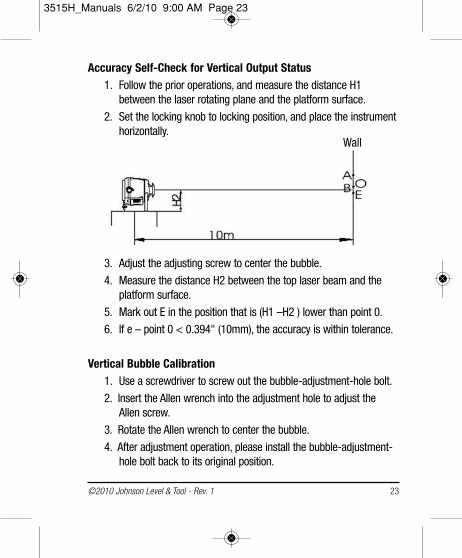
Instruction ManualCongratulations on your choice of this Self-Leveling Rotary LaserLevel. We suggest you read this instruction manual thoroughly beforeusing the instrument. Save this instruction manual for future use.
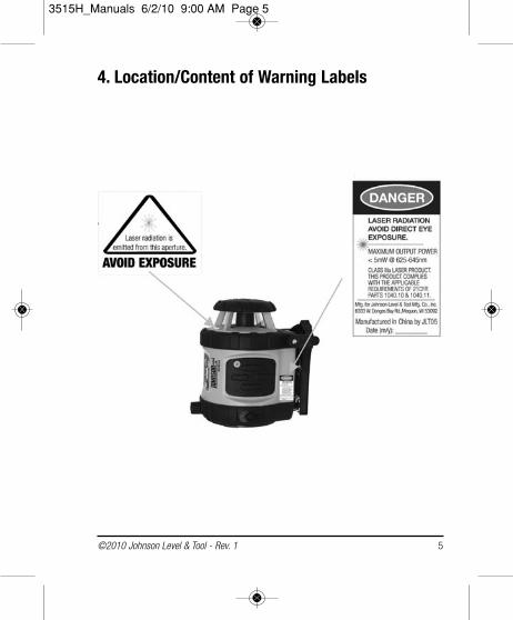
This is a Class IIIa laser tool and is manufactured to comply with CFR 21, parts 1040.10 and 1040.11 as well as internationalsafety rule IEC 285.
Table of Contents 1. Kit Contents 2. Features and Functions3. Safety Instructions4. Location/Content
of Warning Labels5. Location of Parts/Components6. Operating Instructions7. Using the Product
8. Self-Check & Fine Calibration9. Technical Specifications10. Application Demonstrations11. Care and Handling12. Product Warranty 13. Warranty Registration14. Accessories
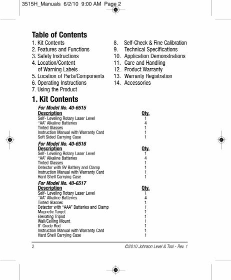
1. Kit ContentsFor Model No. 40-6515Description Qty.Self- Leveling Rotary Laser Level 1“AA” Alkaline Batteries 4Tinted Glasses 1Instruction Manual with Warranty Card 1Soft Sided Carrying Case 1
For Model No. 40-6516Description Qty.Self- Leveling Rotary Laser Level 1“AA” Alkaline Batteries 4Tinted Glasses 1Detector with 9V Battery and Clamp 1Instruction Manual with Warranty Card 1Hard Shell Carrying Case 1 For Model No. 40-6517Description Qty.Self- Leveling Rotary Laser Level 1“AA” Alkaline Batteries 4Tinted Glasses 1Detector with “AAA” Batteries and Clamp 1Magnetic Target 1Elevating Tripod 1Wall/Ceiling Mount 18’ Grade Rod 1Instruction Manual with Warranty Card 1Hard Shell Carrying Case 1
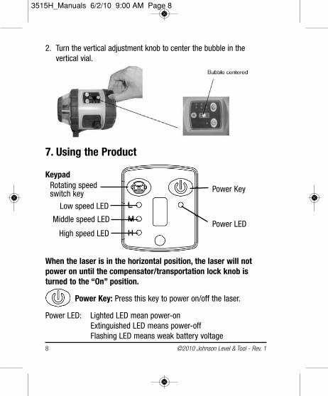
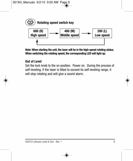
Note: When starting the unit, the laser will be in the high-speed rotating status.When switching the rotating speed, the corresponding LED will light up.
Out of LevelSet the lock knob to the on position. Power on. During the process ofself-leveling, if the laser is tilted to exceed its self-leveling range, itwill stop rotating and will give a sound alarm.
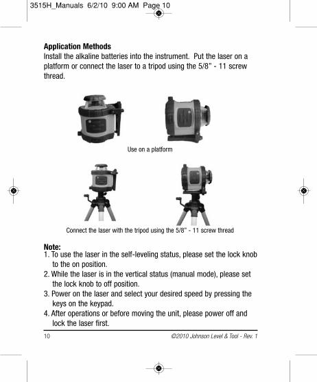
Application MethodsInstall the alkaline batteries into the instrument. Put the laser on aplatform or connect the laser to a tripod using the 5/8” - 11 screwthread.
Note:1. To use the laser in the self-leveling status, please set the lock knob
to the on position.2. While the laser is in the vertical status (manual mode), please set
the lock knob to off position.3. Power on the laser and select your desired speed by pressing the
keys on the keypad.4. After operations or before moving the unit, please power off and
lock the laser first.
Use on a platform
Connect the laser with the tripod using the 5/8” - 11 screw thread
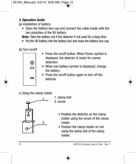
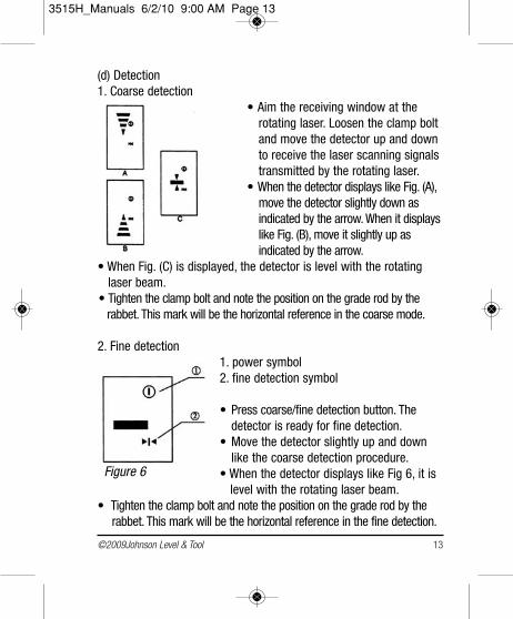
• Aim the receiving window at therotating laser. Loosen the clamp boltand move the detector up and downto receive the laser scanning signalstransmitted by the rotating laser.
• When the detector displays like Fig. (A),move the detector slightly down as indicated by the arrow. When it displayslike Fig. (B), move it slightly up as indicated by the arrow.
• When Fig. (C) is displayed, the detector is level with the rotating laser beam.
• Tighten the clamp bolt and note the position on the grade rod by the rabbet. This mark will be the horizontal reference in the coarse mode.
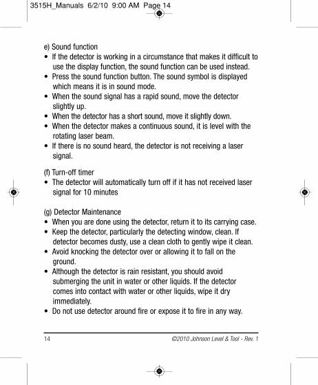
2. Fine detection1. power symbol2. fine detection symbol
• Press coarse/fine detection button. Thedetector is ready for fine detection.
• Move the detector slightly up and downlike the coarse detection procedure.
• When the detector displays like Fig 6, it is level with the rotating laser beam.
• Tighten the clamp bolt and note the position on the grade rod by therabbet. This mark will be the horizontal reference in the fine detection.
e) Sound function• If the detector is working in a circumstance that makes it difficult to
use the display function, the sound function can be used instead.• Press the sound function button. The sound symbol is displayed
which means it is in sound mode. • When the sound signal has a rapid sound, move the detector
slightly up.• When the detector has a short sound, move it slightly down.• When the detector makes a continuous sound, it is level with the
rotating laser beam.• If there is no sound heard, the detector is not receiving a laser
signal.
(f) Turn-off timer• The detector will automatically turn off if it has not received laser
signal for 10 minutes
(g) Detector Maintenance• When you are done using the detector, return it to its carrying case.• Keep the detector, particularly the detecting window, clean. If
detector becomes dusty, use a clean cloth to gently wipe it clean.• Avoid knocking the detector over or allowing it to fall on the
ground.• Although the detector is rain resistant, you should avoid
submerging the unit in water or other liquids. If the detectorcomes into contact with water or other liquids, wipe it dry immediately.
• Do not use detector around fire or expose it to fire in any way.
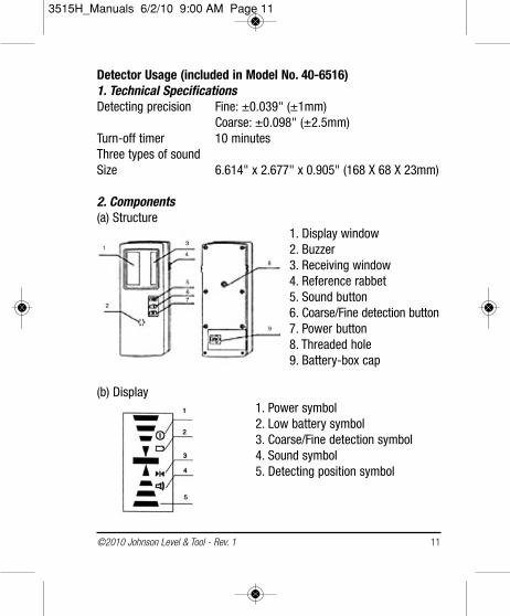
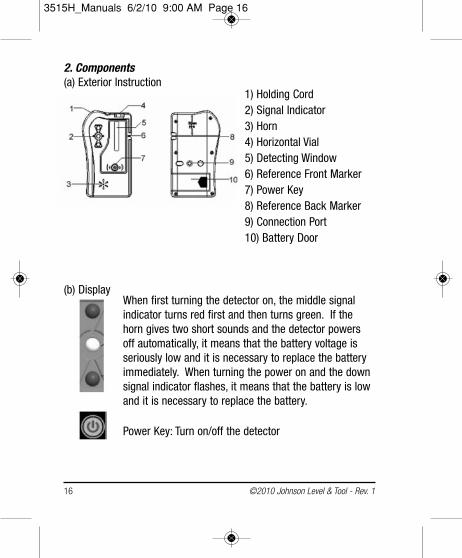
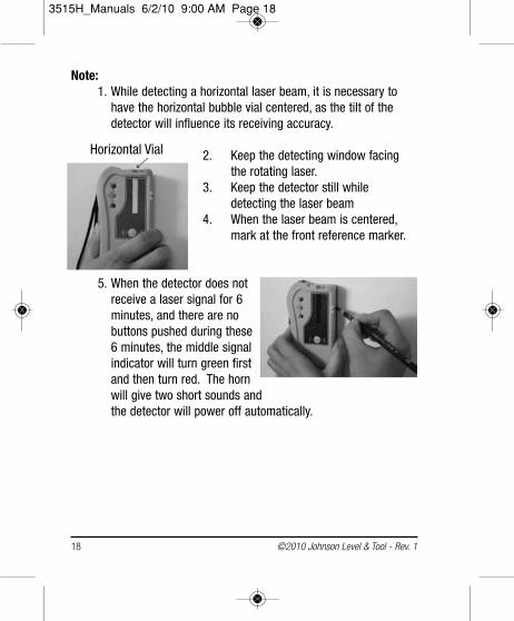
1) Holding Cord2) Signal Indicator3) Horn4) Horizontal Vial5) Detecting Window6) Reference Front Marker7) Power Key8) Reference Back Marker9) Connection Port10) Battery Door
(b) DisplayWhen first turning the detector on, the middle signal indicator turns red first and then turns green. If thehorn gives two short sounds and the detector powersoff automatically, it means that the battery voltage is seriously low and it is necessary to replace the batteryimmediately. When turning the power on and the downsignal indicator flashes, it means that the battery is lowand it is necessary to replace the battery.
Note:1. While detecting a horizontal laser beam, it is necessary to
have the horizontal bubble vial centered, as the tilt of the detector will influence its receiving accuracy.
2. Keep the detecting window facing the rotating laser.
3. Keep the detector still while detecting the laser beam
4. When the laser beam is centered, mark at the front reference marker.
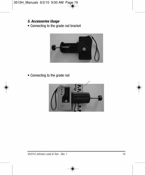
5. When the detector does not receive a laser signal for 6 minutes, and there are no buttons pushed during these 6 minutes, the middle signal indicator will turn green first and then turn red. The horn will give two short sounds and the detector will power off automatically.
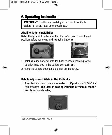
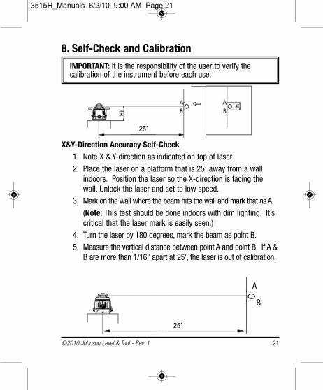
IMPORTANT: It is the responsibility of the user to verify the calibration of the instrument before each use.
X&Y-Direction Accuracy Self-Check1. Note X & Y-direction as indicated on top of laser.
2. Place the laser on a platform that is 25’ away from a wallindoors. Position the laser so the X-direction is facing thewall. Unlock the laser and set to low speed.
3. Mark on the wall where the beam hits the wall and mark that as A.
(Note: This test should be done indoors with dim lighting. It’scritical that the laser mark is easily seen.)
4. Turn the laser by 180 degrees, mark the beam as point B.
5. Measure the vertical distance between point A and point B. If A &B are more than 1/16” apart at 25’, the laser is out of calibration.
6. Turn the laser 90° and place it on the platform. Position thelaser so the Y-direction is facing the wall. Perform Y-directionself-check with the same method as X-direction self-check,and mark point C and point D by turns.
7. If point C and point D are within 1/16” at 25’, the accuracy iswithin tolerance.
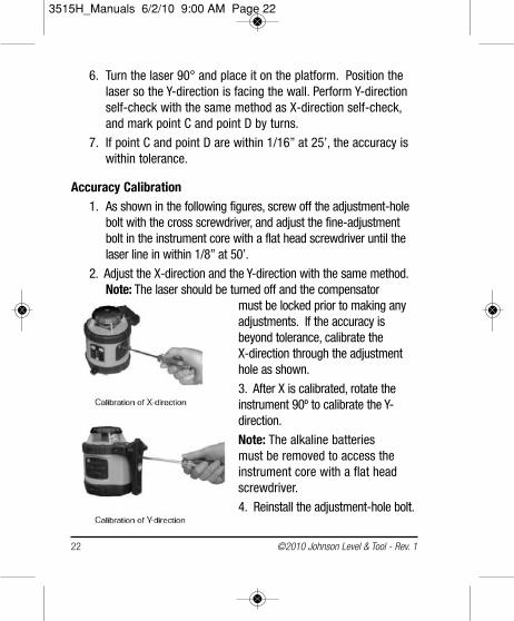
Accuracy Calibration1. As shown in the following figures, screw off the adjustment-hole
bolt with the cross screwdriver, and adjust the fine-adjustmentbolt in the instrument core with a flat head screwdriver until thelaser line in within 1/8” at 50’.
2. Adjust the X-direction and the Y-direction with the same method.Note: The laser should be turned off and the compensator
must be locked prior to making anyadjustments. If the accuracy isbeyond tolerance, calibrate the X-direction through the adjustmenthole as shown.
3. After X is calibrated, rotate the instrument 90º to calibrate the Y-direction.
Note: The alkaline batteries must be removed to access theinstrument core with a flat headscrewdriver.
Note: If you fail to calibrate the accuracy according to the abovesteps, please contact Johnson Level & Tool for service.
9. Technical SpecificationsLaser Wavelength 635nm±10nmLaser Classification Class IIIaMaximum Power Output ≤5mW Accuracy ±1/8"/50 ft. (±2mm/10m)Interior Range Up to 200 ft (60m) diameter depending
upon light conditions Exterior Range Up to 800 ft (240 m) diameter with detectorSelf-Leveling Range ±3°Power Supply 4 “AA” alkaline batteries (included)Battery Life Approx. battery life 20 hours continuous useDimensions 5” x 6 1/2” x 6 1/2” (126x170x168mm)Weight 3.3 lbs (1.5 Kg)Working Temperature 14°F to 113°F (-10°C to +45°C) Center screw thread 5/8" – 11Rotation Speed 200 rpm, 400 rpm, 600 rpmIP protection class 54
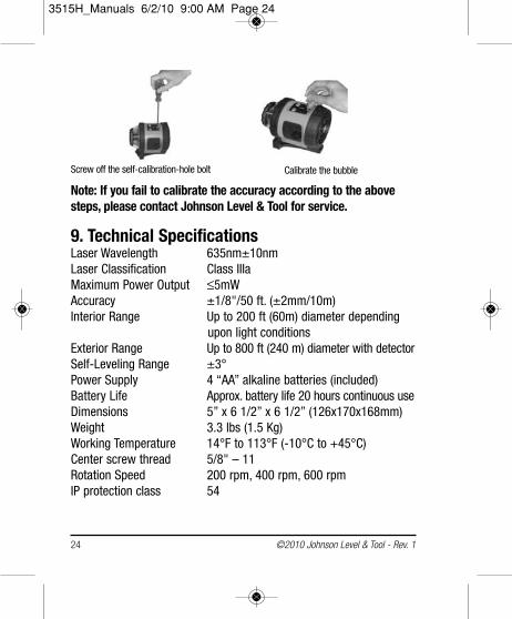
Screw off the self-calibration-hole bolt Calibrate the bubble
•This laser unit is a precision tool that must be handled with care.•Avoid exposing unit to shock vibrations and extreme temperatures.•Before moving or transporting the unit, make sure that the unit is
turned off.•Remove the batteries when storing the unit for an extended time
(more than three months) to avoid damage to the unit should thebatteries deteriorate.
•Always store the unit in its case when not in use.•Avoid getting the unit wet.•Keep the laser unit dry and clean, especially the laser output
window. Remove any moisture or dirt with a soft, dry cloth.•Do not use harsh chemicals, strong detergents or cleaning solvents
to clean the laser unit.
12. Product WarrantyJohnson Level & Tool offers a three year limited warranty on each of itsproducts. You can obtain a copy of the limited warranty for a JohnsonLevel & Tool product by contacting Johnson Level & Tool's CustomerService Department, as provided below, or by visiting our web site atwww.johnsonlevel.com. The limited warranty for each product contains various limitations and exclusions.
Do not return this product to the store/retailer or place of purchase. Non-warranty repairs and course calibration must be done by anauthorized Johnson® service center or Johnson Level & Tool's limitedwarranty, if applicable, will be void and there will be NO WARRANTY.Contact one of our service centers for all non-warranty repairs. A list
of service centers can be found on our web site at www.johnsonlevel.comor by calling our Customer Service Department. Contact ourCustomer Service Department for Return Material Authorization (RMA)for warranty repairs (manufacturing defects only). Proof of purchaseis required.
NOTE: The user is responsible for the proper use and care of the product. It is the responsibility of the user to verify the calibration of theinstrument before each use.
For further assistance, or if you experience problems with this productthat are not addressed in this instruction manual, please contact ourCustomer Service Dept.
In the U.S., contact Johnson Level & Tool’s Customer ServiceDepartment at 888-9-LEVELS.
In Canada, contact Johnson Level & Tool’s Customer ServiceDepartment at 800-346-6682.
13. Warranty RegistrationEnclosed with this instruction manual you will find a warranty registration card to be completed for your product. You will need tolocate the serial number for your product that is located on the bottomof the unit. PLEASE NOTE THAT IN ADDITION TO ANY OTHER LIMITATIONS OR CONDITIONS OF JOHNSON LEVEL & TOOL'S LIMITED WARRANTY, JOHNSON LEVEL & TOOL MUST HAVERECEIVED YOUR PROPERLY COMPLETED WARRANTY CARD ANDPROOF OF PURCHASE WITHIN 30 DAYS OF YOUR PURCHASE OFTHE PRODUCT OR ANY LIMITED WARRANTY THAT MAY APPLYSHALL NOT APPLY AND THERE SHALL BE NO WARRANTY.
14. AccessoriesJohnson® accessories are available for purchase through authorizedJohnson® dealers. Use of non-Johnson® accessories will void anyapplicable limited warranty and there will be NO WARRANTY. If you needany assistance in locating any accessories, please contact ourCustomer Service Department.
In the U.S., contact Johnson Level & Tool’s Customer ServiceDepartment at 888-9-LEVELS.
In Canada, contact Johnson Level & Tool’s Customer ServiceDepartment at 800-346-6682.