47
HENF 91021 INSTRUCTION MANUAL DLTC PLC Line Traps Installation, Commissioning Maintenance and Operation, Transportation and Storage

HENF 91021
INSTRUCTION MANUAL
DLTCPLC Line Traps
Installation, CommissioningMaintenance and Operation,Transportation and Storage

Instruction Manual DLTC HENF 91021
Edition D Language: EN Page: II
Revisionstatus:
Edition Prepared Checked Approved
Edition D 2002-08-12Doser
2002-08-12Doser
2002-08-12Mayer
Author’s address:
ABB SwitzerlandUtility AutomationDepartment UTAKCH-5300 Turgi / Switzerland
Call Center: +41 844 845 845E-mail: [email protected]: www.abb.ch© ABB
File name: 91021_020812

Instruction Manual DLTC
Edition D Language: EN Page: III
About this Document
This instruction manual applies to the PLC Line Traps Type DLTC.
We reserve all rights to this document, even in the event that a patent is issued and a differentcommercial proprietary right is registered. Improper use, in particular reproduction anddissemination to third parties, is not permitted.
This document has been carefully checked. If the user nevertheless detects any errors, he isasked to notify us as soon as possible.
The data contained in this manual is intended solely for the product description and is not to bedeemed to be a statement of guaranteed properties. In the interests of our customers, weconstantly seek to ensure that our products are developed to the latest technological standards.As a result, it is possible that some differences between the product and the product descriptionor the instruction manual may occur.


Instruction Manual DLTC Contents
Edition D Language: EN Page: 0-1
0 CONTENTS
0 Contents .......................................................................................................................................... 0-1
1 Introduction ...................................................................................................................................... 1-11.1 Using the manual............................................................................................................................. 1-11.2 Application of line trap type DLTC ................................................................................................... 1-11.3 Requirements to be met by the service personnel .......................................................................... 1-11.4 Guarantee provisions....................................................................................................................... 1-11.5 General information about PLC Coupling........................................................................................ 1-11.6 Purpose of PLC line traps................................................................................................................ 1-21.7 PLC Coupling principles .................................................................................................................. 1-3
2 Safety Instruction and Warnings...................................................................................................... 2-1
3 System description .......................................................................................................................... 3-13.1 General ............................................................................................................................................ 3-13.2 Design of PLC line trap.................................................................................................................... 3-13.3 Main coil........................................................................................................................................... 3-23.4 Surge arrester.................................................................................................................................. 3-23.5 Tuning device .................................................................................................................................. 3-2
4 Transportation and Storage............................................................................................................. 4-14.1 Transportation ................................................................................................................................. 4-14.2 Transportation damage ................................................................................................................... 4-14.3 Unpacking........................................................................................................................................ 4-14.4 Storage ............................................................................................................................................ 4-1
5 Installation and mounting instructions ............................................................................................. 5-15.1 Safety information............................................................................................................................ 5-15.2 Mounting modes .............................................................................................................................. 5-15.3 Mounting of optional accessories .................................................................................................... 5-15.4 Assembly of support insulators, CC or CVT and mounting of line trap ........................................... 5-65.5 Connections to the line droppers from overhead line and switchyard ............................................. 5-65.6 General mounting information ......................................................................................................... 5-7
6 Commissioning ................................................................................................................................ 6-16.1 Safety information............................................................................................................................ 6-16.2 Checks during commissioning of equipment................................................................................... 6-1
7 Maintenance .................................................................................................................................... 7-17.1 Safety information............................................................................................................................ 7-17.2 General procedure........................................................................................................................... 7-17.3 Inspection of HF Characteristic of line trap on site .......................................................................... 7-17.4 Replacement of tuning device ......................................................................................................... 7-37.5 Replacement of surge arrester ........................................................................................................ 7-4
8 Appendix.......................................................................................................................................... 8-5


Instruction Manual DLTC HENF 91021
Edition D Language: EN Page: 1-1
1 INTRODUCTION1.1 Using the manual
The manual is written for service personnel in the high voltage (HV) power line environment. Allexisting safety instructions in the client's environment have to be observed and only trained andinstructed personnel should work with the equipment. The manual provides the necessaryinstructions for all the steps in the life-cycle of the equipment, e.g. from transport, storage,commissioning to maintenance. Please refer to the appropriate section for the particular step orfunction.
1.2 Application of line trap type DLTCPower Line Carrier (PLC) systems are used for communication on power lines between powersystem control centres, power stations & sub-stations. The PLC signal has to be coupled to the HV-line by means of PLC coupling equipment. The coupling equipment comprises of coupling device,coupling capacitor or capacitive voltage transformer and PLC line trap type DLTC.
1.3 Requirements to be met by the service personnel
• Service personnel must read and understand the instruction manual before working with theDLTC equipment.
• This product may only be installed by individuals who have received training in procedures forinstalling equipment on high voltage power lines and on PLC coupling equipment.
• The service personnel must strictly follow all precautions and warnings which could causepersonnel injury or damage to the equipment.
1.4 Guarantee provisionsThe manufacturer disclaims any responsibility for hazards and material damage, if the equipment isoperated other than for its intended use as described in this manual or if the equipment is servicedby non qualified personnel.
1.5 General information about PLC CouplingPower line carrier (PLC) links supplied by ABB form the backbone of power utility communicationsystems in all parts of the world. As an economical means of transmitting information and data,PLC has made an important contribution to power system control for many years.
PLC is mainly used to reliably transmit speech, energy management data and power systemprotection signals. In order to meet the varying requirements of power utilities when constructing anew power system or extending an existing one, PLC equipment must be compatible and ofmodular design.

Instruction Manual DLTC HENF 91021
Edition D Language: EN Page: 1-2
Substation A
Line TrapDLTC
CC/CVT CC/CVT
HV-lineimpedance ZI
Line TrapDLTC
Transport of electrical energy
Transmission of data, speech and protection signal
PLC-Terminal
PLC-Terminal
Coupling DeviceMCD 80
Coupling DeviceMCD80
Substation B
For injection and extraction of PLC signals on high voltage overhead lines and cables a PLCcoupling system is being used at both ends of the PLC transmission path. A complete set ofcoupling system comprises the PLC line trap, the coupling capacitor (CC) or capacitive voltagetransformer (CVT) and the PLC coupling device. Its purpose is to permit the PLC signal to pass, butreject the power system frequency and protect the communications equipment from the powersystem voltage and transient overvoltages caused by switching operations and atmosphericdischarges.
1.6 Purpose of PLC line traps
• Provision of defined high-voltage line impedances regardless of configuration of the primarysystem switchgear.
• Prevention of signal losses due to propagation into other lines• Attenuation of RF signal from other parts of the power systems, thus permitting multiple use of
the same frequency bands.
PLC line traps are connected in series with the high-voltage lines and must therefore be rated forthe maximum continuous load current and be able to withstand the maximum fault current at theplace of installation. DLTC line traps are designed according to the latest IEC recommendations.
The main advantages and features of PLC line traps type DLTC are:• Low weight and low volume due to multi-layer techniques.
Easier to suspend, less wind resistance
• Open construction for better cooling and excellent RF characteristics with high Q and low straycapacitanceNo danger of local hot-spots or cracking of insulating materialHigher resonant frequencies than those used for PLC transmission
• Solid construction permits high mechanical loads on terminals.
• High voltage withstand of tuning units ensures high reliability• Transient overvoltage protection by metal oxide arresters with better protection characteristics
than arc-gap arresters.Only arresters with a rating of 10kA are used.

Instruction Manual DLTC HENF 91021
Edition D Language: EN Page: 1-3
1.7 PLC Coupling principles
1.7.1 Single-phase coupling (phase-to-ground coupling)This type of coupling is the simpliest type of coupling of PLC signal to the high-voltage line. Since aground fault close to the substation on the phase used for the PLC link can short-circuit the signal,single-phase coupling should only be used for power systems where transmission reliability in theevent of a power system fault is of secondary importance.
1.7.2 Two-phase coupling (phase-to-phase coupling)Coupling to two phases of the power system is much more reliable than coupling to just one phase.A ground fault in this case will normally only cause an additional attenuation of the PLC signal byabout 6 dB. A two-phase coupling scheme consists of two coupling units, one of which includes ahybrid module.Schemes are sometimes also used which couplings to all three phases (three-phase coupling) ortwo phases of one three-phase system and two phases of another three-phase system (intersystemcoupling). All of these types of coupling can be handled by moduls of the MCD80 system. Detailswill be given with project specific documentation.In practice, PLC coupling is a more complex problem since the units at both ends of the HV linehave to be optimised for the conditions prevailing there. In the case of long lines with highattenuation, an analysis of the line is necessary to determine the arrangement with the mostpreferable transmission characteristics. ABB has years of experience in conducting such analyses.Analysis is generally not necessary for short or non-transposed lines. For a horizontal conductorconfiguration, the centre phase is chosen for single-phase coupling and two adjacent phases fortwo-phase coupling. In the case of configurations with a vertical distribution, phases as high and asclose as possible should be chosen. How many phases are used is largely a question of thereliability requested for the PLC link.
1.7.3 HV line impedance
Impedances of HV lines lie typically in the range 350 Ω to 450 Ω per phase for single conductorsand 250 Ω to 350 Ω per phase for bundle conductors. In order to terminate the coupling filtercorrectly for average operating conditions, the shunting effect of the line trap and the stationimpedance has to be taken into account. The line traps which are inserted to compensate as far aspossible the shunt impedance of the substation are designed such that the minimum shuntimpedance is 1.41 times the line impedance. Accordingly, the impedance of PLC line traps shall beabout 570 Ω for single conductor lines and about 400 Ω for bundle conductor lines.
The corresponding impedance for HV cables is much lower and has to be calculated in eachindividual case. In these cases coupling arrangement and line trap impedance has to be designedindividually.


Instruction Manual DLTC HENF 91021
Edition D Language: EN Page: 2-1
2 SAFETY INSTRUCTION AND WARNINGS
DANGERProtect your life while making any modifications!
Before handling any part of the electrical circuits:• Be sure that the transmission lines are not
energized.• Apply grounding clamps to high voltage line
for earthing.• Follow your company’s and local safety
regulations
DANGERDo not attempt to handle, install, use or servicethis product until thoroughly familiar with theinformations given in this instruction book.
DANGERHazardous voltage can shock, burn or causedeath.
This product may only be installed by individualswho have received training in procedures forinstalling equipment on high voltage power linesand on PLC coupling equipment.
DANGERAlways consider following warnings:
• A power line can carry dangerous voltageseven when switched off.

Instruction Manual DLTC HENF 91021
Edition D Language: EN Page: 3-1
3 SYSTEM DESCRIPTION3.1 General
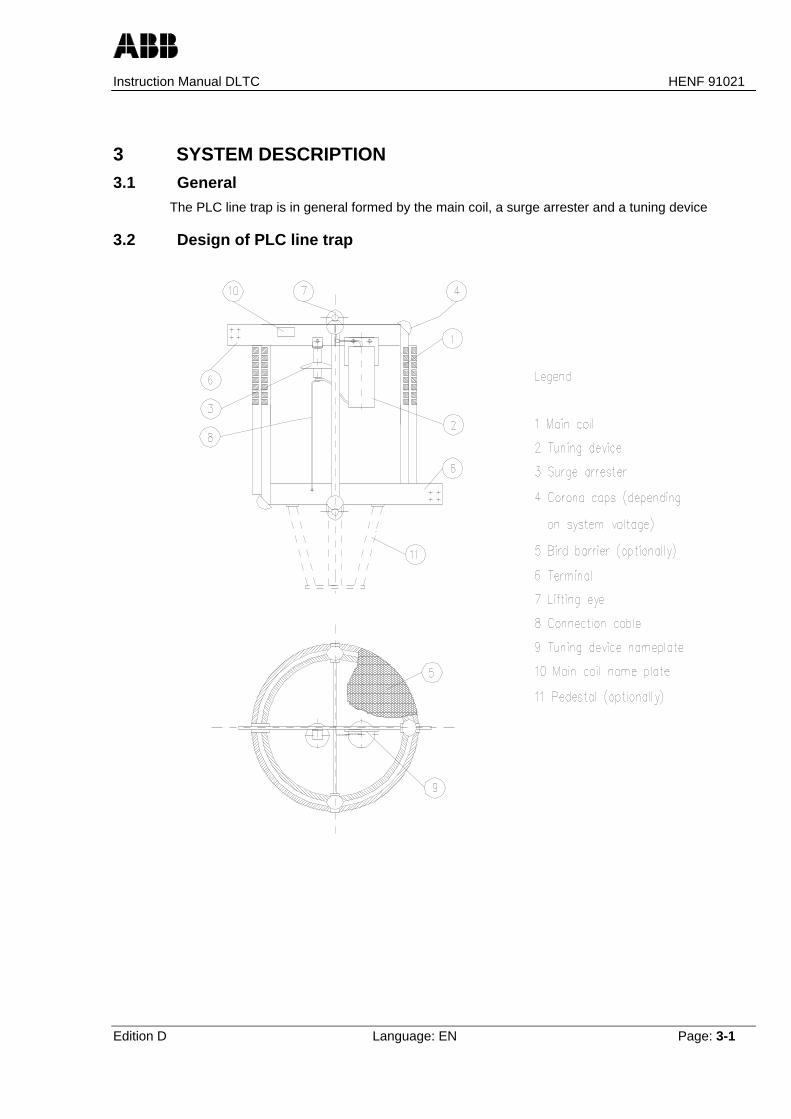
The PLC line trap is in general formed by the main coil, a surge arrester and a tuning device
3.2 Design of PLC line trap

Instruction Manual DLTC HENF 91021
Edition D Language: EN Page: 3-2
3.3 Main coil
The coil conductor is of square section aluminium and the turns are spaced by impregnated fibreglass tape or spacer rods depending on rating. The entire main coil is impregnated with a two-component epoxy resin of known good outdoor performance. Depending on the rated current andrated inductance, the main coil is wound with either one or several layers. Especially shaped fibreglass spacers or spacer rods keep the layers of multiple layer line traps apart. The multiple layerwinding technique enables compact and robust line traps having a small diameter and low height.
• The spider supports in the ends of the coils are held together by tie bars of fibre glass reinforcedepoxy or spacer rods.
• To achieve a reliable corrosion-proof connection, the HV terminals are welded directly to theends of the winding. Generally, vertical flat terminals with 4 or 9 holes are fitted, but round orhorizontal flat terminals can be welded to the spiders on request.
• Because of their low weight, most DLTC coils can be mounted on coupling capacitors orcapacitive voltage transformers.
• They can also be mounted on insulator posts or simply suspended.
• All coils are equipped with lifting eyes on both sides. Optionally, a pedestal, bird barriers and thecorona shield can also be attached to the spiders. The corona protection consists of eithercorona caps at the edges or corona rings, needed at the higher power system voltages.
• The tuning unit and the surge arrester are secured inside the main coil.
The electrical characteristics of the main coils are indicated on the rating plate which is placed onthe top spider.
3.4 Surge arresterThe surge arrester protects the main coil and tuning device against overvoltages. All line traps areequipped with MO-surge arresters based on extremely non-linear metal oxide varistors. Thecomponents of the surge arresters are completely sealed in one housing and therefore protectedagainst environmental conditions.The electrical characteristics of the surge arresters are indicated on the rating plate which is placedat the top of the unit.The surge arrester is fixed with screws at the upper spider.
3.5 Tuning deviceThe tuning device is connected in parallel with the main coil and the surge arrester. It provides adefined impedance or blocking resistance in the frequency band. The tuned circuit is usually of thedual-circuit broadband type. This solution has proved to produce the best results in the majority ofcases.Alternatively, the line trap can be tuned as a damped single frequency filter. The main characteristicof this type of tuning is its excellent withstand to transient overvoltages.The tuning device may consist of up to 3 packs all of which are electrically connected in parallel.The components of the tuning device are completely sealed in one or more housings and thereforeprotected from environmental conditions. Only the resistors are partly placed outside the housingand surrounded by air for better cooling.The tuning device is fixed with screws at the upper spider.In certain cases no tuning devices are being used.The electrical characteristics of the tuning devices are indicated on the rating plate which is placedat the top of the unit.
Instruction Manual DLTC HENF 91021
Edition D Language: EN Page: 4-1
4 TRANSPORTATION AND STORAGE4.1 Transportation
Line traps are fitted with top lifting eyes which shall be used for lifting during transportation.
All line traps must be fixed on the load floor of the truck or ship by appropriate tows to prevent anymovement or lateral tilting during transportation.
4.2 Transportation damageThe transported goods are to be checked immediately for transport damages. In case of damageplease proceed as follows:
• notify insurance company immediately
• contact the carrier and declare him liable by indicating the damage on the receipt.
• substantiate the carrier´s liability for the damage by sending him a registered letter.
• contact your contractual partner immediately, especially if transported goods were shipped at therisk of the contractual partner.
4.3 UnpackingThe line trap with fitted surge arrester and tuning device is packed in wooden frame crates orsupplied on a wooden pallet with a wooden cover. The line trap is easily removed from the pallet bycutting the plastic tension bands or removing the wooden planks of the crate respectively.
The optional pedestals are either mounted on the wooden pallets under the line trap or packedseparately. Mounting bolts and occasionally other mounting hardware as well as optionally usedcorona caps and bird barriers may be attached to the line trap in small bags fixed to the spiderarms.
During unpacking care should be taken that all packing material, such as wooden braces etc. whichmay have been attached to the tuning device or protective device are removed. Please considerthat wooden braces may be used between the housings of tuning device(s) and arrester.
4.4 StorageThe PLC line traps are shipped in a vertical position. Optionally available support insulators areshipped in a horizontal position. They have to be stored in these positions. DLTC line traps packedin wooden crates or open on palletts are suitable for outdoor storage for reasonable periods of time.The packing serves mainly as protection for mechanical damage.


Instruction Manual DLTC HENF 91021
Edition D Language: EN Page: 5-1
5 INSTALLATION AND MOUNTING INSTRUCTIONS5.1 Safety information
DANGER Follow safety instructions according to chapter 2.
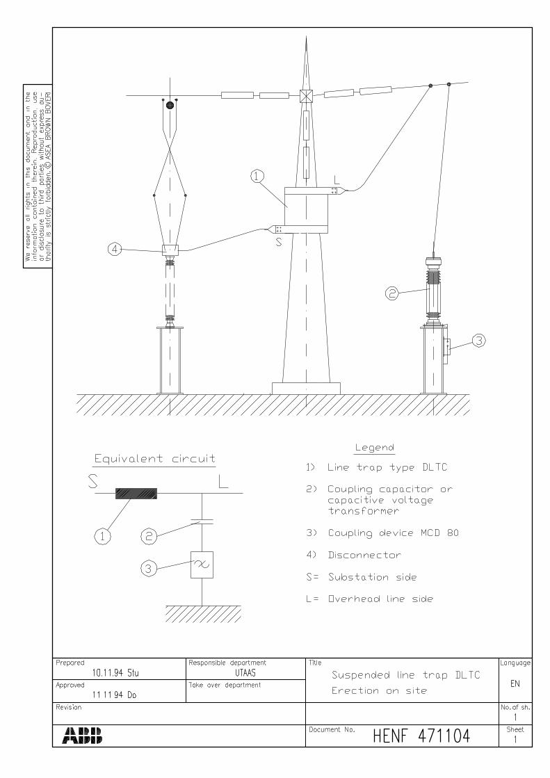
5.2 Mounting modesPLC line traps type DLTC may be suspended or mounted on top of support insulators, couplingcapacitors (CC) or capacitive voltage transformers (CVT). Samples of typical arrangement drawingsare enclosed.
Suspension Mounting
All standard line traps type DLTC are fitted with lifting eyes at the top and the bottom. These liftingeyes can be used for suspension mounting. Special versions for suspension from 2, 3 or 4suspension insulators are available. The maximum force of suspension system of line trapindicated on rating plate of line trap may not be exceeded.
Mounting on post insulator, CC or CVT
Various different pedestals are available for mounting of the line trap on top of support insulators,coupling capacitors (CC) or capacitive voltage transformers (CVT). If the line trap is mounted on topof CC or CVT, the electrical connection between the bottom terminal of line trap and top of CC/CVTwill be carried out by the metallic pedestal itself. The cylindrical pedestal from fiberglass material isfitted with a potential connection between the top terminal and the bottom terminals of this pedestal.
In all cases where PLC line trap is mounted on top of CC or CVT line dropper of overhead line mustbe connected with bottom terminal of the line trap.
Line traps type DLTC may only be mounted in the vertical position.
5.3 Mounting of optional accessories
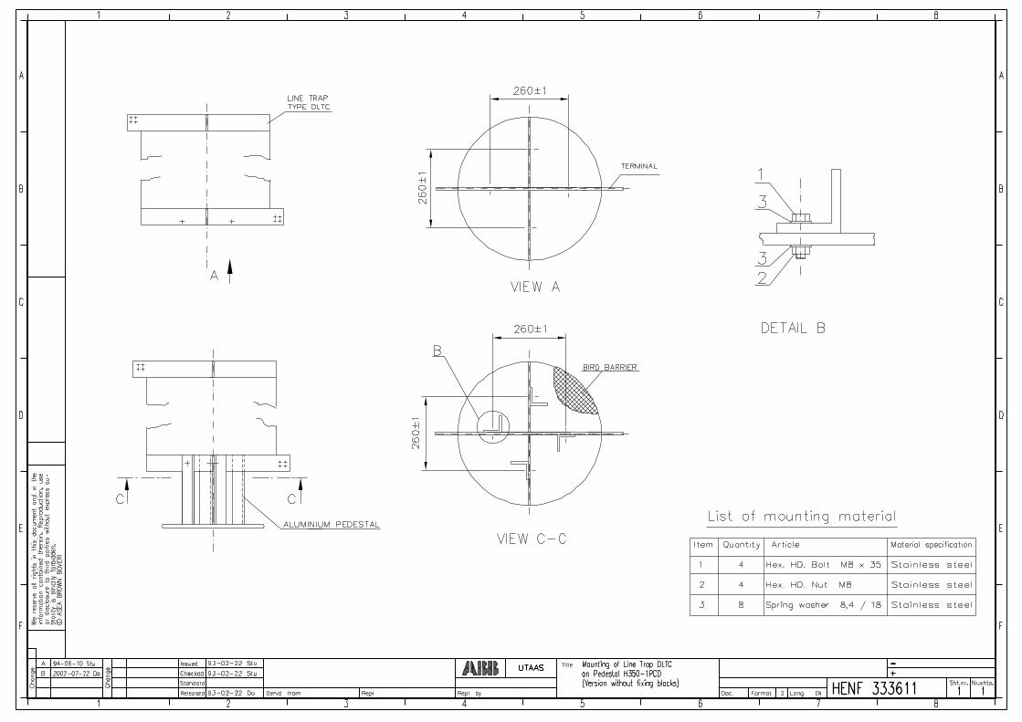
5.3.1 PedestalsDifferent types of pedestals may be supplied. Pedestals with 2 and 4 legs are being useddepending on the type of line trap. Cylindrical pedestals from glassfiber material are being used formounting of line traps on top of 3 or 4 columns of support insulators or coupling capacitors. Theholes in the bottom plate of the pedestal should correspond with the holes of the top flange of thesupport insulator, CC or CVT. Fixing blocks may be used for mounting of pedestal on the lowerspider of line trap in some cases. For mounting of pedestal please refer to project specific drawingsor if these are not available to the enclosed standard drawings.
5.3.2 Bird barriersBird barriers can optionally be attached to the PLC line traps Type DLTC. Their function is toprevent birds from penetration into the main coil and build their nests. They have to be mounted onthe top and bottom side of the PLC line trap. These bird barriers are placed inside of the line trap ina bag together with optional corona caps and other optional mounting material duringtransportation.

Instruction Manual DLTC HENF 91021
Edition D Language: EN Page: 5-2
5.3.2.1 Mounting of bird barrier on top of PLC line trap
• Take out one bird barrier from the bag, which is placed inside of the PLC line trap.
• There are two holes cut into the net. One in the centre for the lifting eye and the second for theterminal at the edge close to the knot of the cord. Push the latter over the terminal as given inpicture 1.
• Push the centre hole of the net over the lifting eye as shown in picture 2
• Distribute the net constantly among the top of the coil and pull the edges down around theperimeter of the coil as shown in picture 3.
• Pull the cord and adjust it round the perimeter so that cord is preferably fixed between secondand third or third and fourth turn of coil as shown in picture 4.
• At last, when bird barrier net is adjusted equally round the perimeter, tie the cord and cut theremaining cord as shown in picture 5.
5.3.2.2 Mounting of bird barrier on bottom side of suspended PLC line trapsLift the line trap and proceed with mounting of the bird barrier on the bottom side in the samesequence as described above for the top side of the line trap. The second bird barrier is placed inthe same bag as the first.
5.3.2.3 Mounting of bottom side bird barrier and pedestal of PLC line trapsThe legs of the pedestals can either be directly mounted to the bottom bar of the PLC line trap or bymeans of fixing blocks, depending on the required pitch circle diameter on the mounting plate. Themounting procedure is slightly different.
Bird barrier mounting procedure for pedestals with fixing blocks
• Take out the second bird barrier from the bag, which is placed inside of the PLC line trap duringtransportation.
• Lift the line trap and mount the fixing blocks provisionally at the lower spider arm as shown inpicture 6. The contact surfaces between fixing blocks and bottom bar of line trap shall becleaned carefully (with wire brush or similar) and subsequently treated with acidless greaseappropriate for electrical connections.
• There are two holes cut into the net. One in the centre for the lifting eye and the second for theterminal at the edge close to the knot of the cord. Push this latter one over the terminal asshown in picture 7.
• Push the centre hole of the net over the lifting eye as given in the section above and distributethe net constantly among the bottom of the coil and push the edges up around the perimeter ofthe coil, pull the cord and adjust the net provisionally round the perimeter.
• Cut small holes in the net where the fixing blocks are located as shown in picture 8. The holesshould only be as big as the fixing blocks to pass through.
• Loose the cord and take down the bottom net partly, place the fixing blocks in the correctposition, push the net over the fixing blocks and mount the pedestal on the fixing blocks asshown in picture 9 by means of the enclosed mounting material. Clean carefully the contactsurface between fixing blocks and legs of pedestal (with wire brush or similar) and treat it withacidless grease appropriate for electrical connections. All screws shall be tightened with theappropriate torque moment. For mounting details please refer to appropriate mounting drawingsin Appendix.
• Distribute the net constantly among the bottom of the coil and push the edges up around theperimeter of the coil, pull the cord and adjust it round the perimeter so that cord is preferablyfixed between second and third turn or third and fourth turn of coil as shown in picture 10.
• At last, when bird barrier is adjusted equally round the perimeter, tie the cord and cut theremaining cord.
Instruction Manual DLTC HENF 91021
Edition D Language: EN Page: 5-3
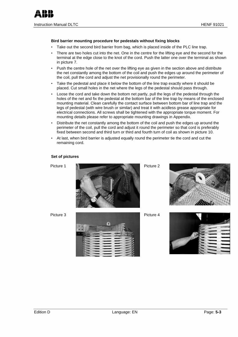
Bird barrier mounting procedure for pedestals without fixing blocks
• Take out the second bird barrier from bag, which is placed inside of the PLC line trap.
• There are two holes cut into the net. One in the centre for the lifting eye and the second for theterminal at the edge close to the knot of the cord. Push the latter one over the terminal as shownin picture 7.
• Push the centre hole of the net over the lifting eye as given in the section above and distributethe net constantly among the bottom of the coil and push the edges up around the perimeter ofthe coil, pull the cord and adjust the net provisionally round the perimeter.
• Take the pedestal and place it below the bottom of the line trap exactly where it should beplaced. Cut small holes in the net where the legs of the pedestal should pass through.
• Loose the cord and take down the bottom net partly, pull the legs of the pedestal through theholes of the net and fix the pedestal at the bottom bar of the line trap by means of the enclosedmounting material. Clean carefully the contact surface between bottom bar of line trap and thelegs of pedestal (with wire brush or similar) and treat it with acidless grease appropriate forelectrical connections. All screws shall be tightened with the appropriate torque moment. Formounting details please refer to appropriate mounting drawings in Appendix.
• Distribute the net constantly among the bottom of the coil and push the edges up around theperimeter of the coil, pull the cord and adjust it round the perimeter so that cord is preferablyfixed between second and third turn or third and fourth turn of coil as shown in picture 10.
• At last, when bird barrier is adjusted equally round the perimeter tie the cord and cut theremaining cord.
Set of pictures
Picture 1 Picture 2
Picture 3 Picture 4

Instruction Manual DLTC HENF 91021
Edition D Language: EN Page: 5-4
Picture 5 Picture 6
Picture 7 Picture 8
Picture 9 Picture 10
5.3.2.4 Mounting of pedestal for PLC line traps which are not equipped with optional bird barrierThe legs of the pedestals can either be directly mounted to the bottom bar of the PLC line trap or bymeans of fixing blocks, depending on the required pitch circle diameter on the mounting plate. Themounting procedure is slightly different.
Mounting procedure for pedestals with fixing blocks
• Clean carefully the contact surface between bottom bar of line trap, fixing blocks and legs ofpedestal (with wire brush or similar) and treat it with acidless grease appropriate for electricalconnections. Place the fixing blocks in the correct position and fix provisionally by means of theenclosed mounting material. Mount the legs of the pedestal on the fixing blocks by means of theenclosed mounting material. All screws shall be tightened with the appropriate torque moment.For mounting details please refer to appropriate mounting drawing in Appendix.
Mounting procedure for pedestals without fixing blocks
• Clean carefully the contact surface between bottom bar of line trap and the legs of pedestal (withwire brush or similar) and treat it with acidless grease appropriate for electrical connections. Fixthe pedestal at the bottom bar of the line trap by means of the enclosed mounting material. Allscrews shall be tightened with the appropriate torque moment. For mounting details please referto appropriate mounting drawing in Appendix.
Instruction Manual DLTC HENF 91021
Edition D Language: EN Page: 5-5
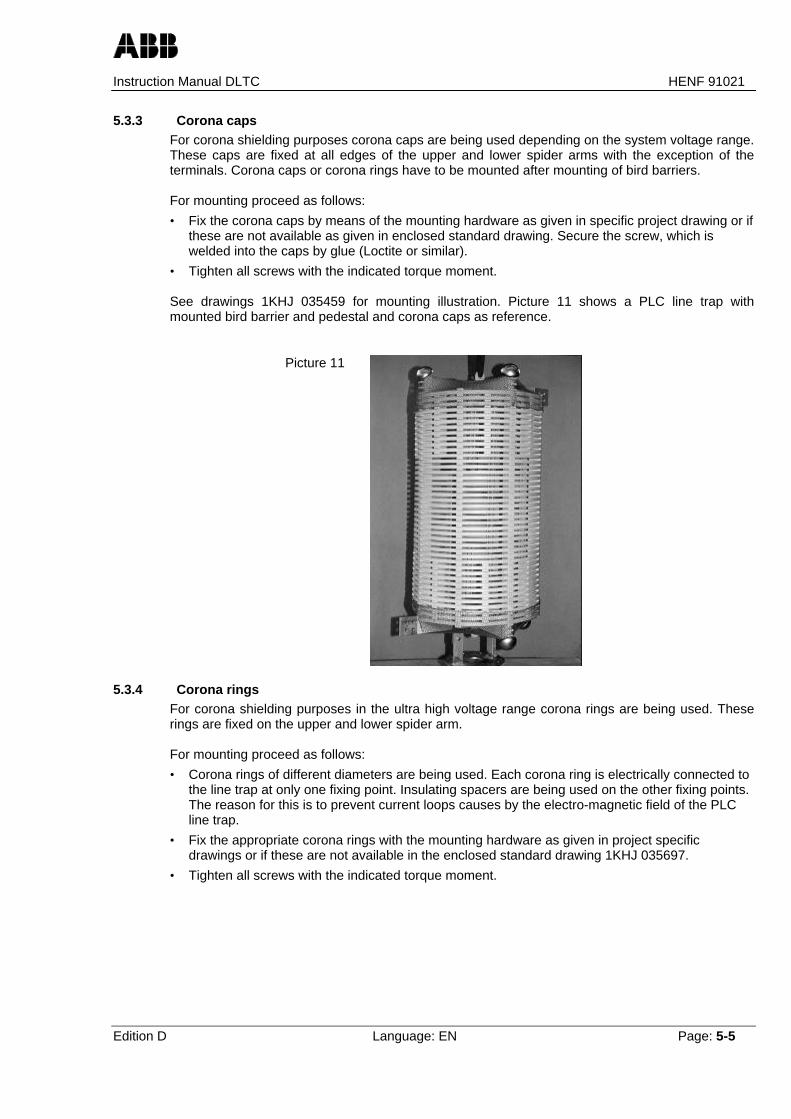
5.3.3 Corona capsFor corona shielding purposes corona caps are being used depending on the system voltage range.These caps are fixed at all edges of the upper and lower spider arms with the exception of theterminals. Corona caps or corona rings have to be mounted after mounting of bird barriers.
For mounting proceed as follows:
• Fix the corona caps by means of the mounting hardware as given in specific project drawing or ifthese are not available as given in enclosed standard drawing. Secure the screw, which iswelded into the caps by glue (Loctite or similar).
• Tighten all screws with the indicated torque moment.
See drawings 1KHJ 035459 for mounting illustration. Picture 11 shows a PLC line trap withmounted bird barrier and pedestal and corona caps as reference.
Picture 11
5.3.4 Corona ringsFor corona shielding purposes in the ultra high voltage range corona rings are being used. Theserings are fixed on the upper and lower spider arm.
For mounting proceed as follows:
• Corona rings of different diameters are being used. Each corona ring is electrically connected tothe line trap at only one fixing point. Insulating spacers are being used on the other fixing points.The reason for this is to prevent current loops causes by the electro-magnetic field of the PLCline trap.
• Fix the appropriate corona rings with the mounting hardware as given in project specificdrawings or if these are not available in the enclosed standard drawing 1KHJ 035697.
• Tighten all screws with the indicated torque moment.

Instruction Manual DLTC HENF 91021
Edition D Language: EN Page: 5-6
5.4 Assembly of support insulators, CC or CVT and mounting of line trap
Assembly of CVT / CCFor mounting of CC or CVT please refer to the product specific manual.For complete assembly please refer to the specific project drawings. Some standard drawings oftypical arrangements are enclosed.
Assembly of support insulator.For complete assembly of support insulators please refer to the specific drawing of this equipment.The elements of the support insulators can clearly be identified by the markings on the uppermostsheds. The marking is referred to in the relevant drawings.Nuts and bolts for assembling of all sections of support insulators are enclosed in the packing of thesupport insulators.
• The contact surfaces on top and bottom of each support insulator element should be cleanedcarefully (with wire brush or similar) and subsequently treated with acidless grease appropriatefor electrical connections.
• Put the column of the bottom section onto the base plate in such a way that the position for thefixing screws are correct.
• Fix the column to the base plate with corresponding screws. Tighten them only slightly so thatthe column still may be moved a little bit during the consequential work.
• Put the column of the next section, if applicable, onto the bottom section in such a way that theposition for the fixing screws are correct.
• Fix this column on the lower column with corresponding bolts, nuts and washers. Tighten themonly slightly so that the columns still may be moved a little bit during the consequential work.
• Proceed with the next sections, if applicable, in the same way as descibed above.
• In case of three or four columns in parallel please proceed with the other columns in the sameway as with the first column.
Mounting of line trap
• The contact surfaces of pedestal and support insulator or CC/CVT should be cleaned carefully(with wire brush or similar) and subsequently treated with acidless grease appropriate forelectrical connections.
• Place the line trap with mounted pedestal in the correct position onto the top flange of the CC,CVT or support insulator respectively. Please observe the correct direction of the terminals ofthe line trap. In all cases where PLC line trap is mounted on top of CC or CVT line dropper ofoverhead line shall be connected to bottom terminal of the line trap.
• Fix the line trap with screws, washers and nuts as given in the project specific drawing or if thisis not available according to the enclosed standard drawing.
• Tighten all screws of support insulator, CC or CVT and line trap with the indicated torquemoment.
5.5 Connections to the line droppers from overhead line and switchyardThe line trap is connected to the overhead line and substation equipment by means of aluminiumterminals placed at the spiders of the line traps in radial direction.Unless otherwise specified, terminals of line traps of type DLTC having inner diameters of 700mmmay not be stressed for pull in excess of 1500N in any direction. Terminals of line traps of typeDLTC with inner diameter above 700mm may not be stressed for pull in excess of 3000 in anydirection unless otherwise specified.

Instruction Manual DLTC HENF 91021
Edition D Language: EN Page: 5-7
To ensure minimum contact resistance and to avoid corrosion the following practice isrecommended:
• For direct connection only clamps from aluminium are suitable. Clamps from other materialssuch as copper or bronze etc. shall be connected via approved bi-metal adapters.
• The contact surfaces must be cleaned carefully (with wire brush or similar) and subsequentlytreated with acidless grease, approved for electrical connections in HV-substations.
• Antimagnetic and non-corroding screws and nuts shall be used.
• Minimum contact resistance can be obtained by using spring washers.
• All screws shall be tightened with the appropriate torque moment.
The line-side terminal of the line trap must electrically be connected to the CC or the CVT. If linetrap is mounted on top of CC or CVT, lower terminal of line trap has to be connected with linedroppers from overhead line.
5.6 General mounting informationAntimagnetic screws and nuts should be used for connecting clamps to the terminals of line traps.This is for to eliminate the heating effect of eddy currents caused by the electromagnetic field ofPLC line traps.
No magnetic materials shall be used in a distance of half coil diameter around the PLC line trap.
Recommended torque moments for screw connections from stainless steel A2:
Screw connection with bolts and nutsof stainless steel type A2
Recommendedtorque moment
M6 8.8 NmM8 21.4 NmM10 44 NmM12 74 NmM14 119 NmM16 183 Nm
These values are applicable unless other values are given in the relevant drawings.
All bolt and nut connections have to be greased.


Instruction Manual DLTC HENF 91021
Edition D Language: EN Page: 6-1
6 COMMISSIONING6.1 Safety information
DANGER Follow safety instructions according to chapter 2.
6.2 Checks during commissioning of equipment
• All packing material removed?
• All material mounted as described in installation instruction and in drawings of equipment of thisproject?
• Follow the path of the PLC-signal from overhead line which shall have direct connection to thetop of CC/CVT.
• Make sure that line trap is electrically connected between top of CC or CVT and switchgear ofsubstation.
• All bolts of tuning device, surge arrester, main coil, pedestal, support insulators, line dropperssecurely fastened with appropriate torque moment?
• Make sure that tuning device of required tuning range is connected in cases where PLC line trapis fitted with several tuning devices of different tuning ranges for frequency change.
• If cylindrical pedestals from glassfiber materials are used:Check inner potential connection of cylindrical pedestal. Measure contact resistance betweenlower terminal of line trap and uppermost flanges of support insulator or CC columns.Resistance measured shall be below 100mΩ.


Instruction Manual DLTC HENF 91021
Edition D Language: EN Page: 7-1
7 MAINTENANCE7.1 Safety information
DANGER Follow safety instructions according to chapter 2.
7.2 General procedure The line traps do not contain any parts subject to wear and they are therefore considered to bemaintenance-free in this respect. However, it is recommended that the following inspections or operations are carried out duringnormal circuit maintenance intervals:
• Check whether all bolts of tuning device, surge arrester, main coil, pedestal, support insulators,CC, CVT respectively and line droppers are securely fastened with correct torque moment.
• In case of heavy pollution by conducting particles cleaning is recommended.
• Check of painting. If paint “touch up” is necessary, line trap should be cleaned and exposedparts should be painted with polyurethane laquer. Specifications obtainable from manufacturer.
7.3 Inspection of HF Characteristic of line trap on siteThe PLC line trap provides a defined impedance or blocking resistance in the frequency bandprescribed for the PLC channel. For tuning purpose a tuning device is connected in parallel with themain coil and the surge arrester. The tuned circuit is usually of the dual-circuit broadband type. Theinsulation level of the tuning device has been selected with respect to the expected voltage stress.
If there are doubts regarding the HF-performance of the the line trap the blocking impedance canbe measured. The most common method of carrying out this measurement is the bridge circuitmethod which is normally only available in the workshop of the line trap manufacturer. The followingmeasuring circuit is therefore recommended for the measurement of blocking impedance on site.
overhead line
Overhead line must be switched off and earthed by auxiliary
earth connectionDisconnector must be in open position
Principle diagram for blocking impedance measurement
Main switch Disconnector Line Trap
Measuring instruments

Instruction Manual DLTC HENF 91021
Edition D Language: EN Page: 7-2
PLC Line Trap
Line dropper to overhead line
Overhead line must be
switched off and earthed by auxiliary earth
connection
This is the only earth point of measuring circuit
HF-Generator, 24-500kHz, low source impedance, battery powered
Resistor, low inductive, about 10 Ohm (value must be low compared with impedance of line trap)
G
U2
U1RH
G
RH
Disconnector must be in open position
To disconnector
Measuring circuit for blocking impedance measurement
Formula for calculation of Impedance |Z| based on measured voltage levels U1 and U2:
| Z | = ( U1 / U2 - 1 ) * R H
The proposed measuring instruments are common for commissioning of PLC transmissionsystems. The use of selective voltmeters for measuring of U1 and U2 is recommended. Theblocking impedance of the PLC line trap according to IEC 60353 can be measured with this circuit.Please consider that the resistive component of blocking impedance can not be measured with thiscircuit.
When comparing the measured impedance curve with the impedance curve supplied with the newequipment by the manufacturer some deviations are normal due to a measuring error from straycapacitance of the long leads to the terminals of the line trap on site. Nevertheless a decisionwhether tuning device has been damaged or not can be derived clearly from impedancemeasurement as impedance characteristic of line trap will be completely different if elements of thetuning device have been damaged by transients during operation.

Instruction Manual DLTC HENF 91021
Edition D Language: EN Page: 7-3
7.4 Replacement of tuning deviceThe rating plate of the tuning device indicates the actual impedance or resistive component ofimpedance and the specified frequency range as well as the matching type of main coil and surgearrester. In case of new frequency allocations or extensions in the PLC-system changes in theblocking impedance characteristic of line traps may be necessary. New tuning devices with differentblocking bands can be manufactured and delivered for each line trap on request.
For order of new tuning devices and surge arresters please contact your local ABB sales office andsubmit following data:
• Serial number of existing tuning device
• Type, current rating and inductance of line trap
• Serial number of main coil.
• Required blocking impedance
• Required blocking frequency band
Removal:1. In case line trap is provided with bird barriers, remove the upper bird barrier. Note that corona
caps resp. rings must be removed before lifting the upper bird barrier.2. Loosen the cable connection at the upper terminal of the tuning device. The second nut of the
screw connection must be retained with a fork wrench. Some of the tuning devices are alreadyequipped with cables. In this case loosen the cables of the tuning device at the respectiveterminals.
3. Loosen the two fixing screws of the tuning device in the upper clamping bar and take the tuningdevice out of the main coil as far as permitted by the cable connected to the lower terminal oftuning device.
4. Loosen the cable connection at the lower terminal of the tuning device. The second nut of thescrew connection must be retained with a fork wrench. This is no longer necessary with tuningdevices already equipped with cables.
5. Remove the tuning device completely.
Installation:1. Check rating plate whether characteristics of the new tuning device are correct and insulation
level is appropriate.2. Fasten the cable connection at the lower terminal of the tuning device with nut and washers of
same type. The second nut of the screw connection must be retained with a fork wrench. Iftuning device is already equipped with cables, cut these cables to the same length as cables ofreplaced tuning device and crimp the appropriate cable terminals at the ends.
3. Place the tuning device inside the main coil and fix it by means of the two screw connections onthe upper clamping bar. Please make sure that the Al-side of the bimetallic washers is on theclamping bar side of the screw connection. Use screw connections of same type as formertuning device has been connected.
4. Fasten the upper cable connection at the upper terminal of the tuning device by means ofwashers and nuts of the same type. The second nut of the screw connection must be retainedwith a fork wrench. If tuning device is already equipped with cables, fasten both cable terminalsat the same terminals where former tuning device has been fastened.
5. Tighten all screws with the recommended torque moments.6. Install bird barrier, corona caps or corona rings at upper spider, if applicable.

Instruction Manual DLTC HENF 91021
Edition D Language: EN Page: 7-4
7.5 Replacement of surge arresterThe rating plate of the surge arrester indicates its ratings. Use surge arresters with the appropriaterating only!
Removal:1. In case line trap is provided with bird barriers, remove the upper bird barrier. Note that corona
caps resp. rings must be removed before lifting the upper bird barrier.2. Loosen the cable connections at the upper and lower terminal of the surge arrester. The second
nut of the screw connection must be retained with a fork wrench.3. Loosen the two fixing screws of the surge arrester at the upper clamping bar and take surge
arrester out of the main coil.
Installation:1. Check rating plate whether characteristics of the new surge arrester are correct. Never use
surge arresters with lower ratings!2. Place the surge arrester inside the main coil and fix it by means of the two screw connections on
the upper clamping bar. Please make sure that the Al-side of the bimetallic washer is on theclamping bar side of the screw connection. Use screw connections of same type as formersurge arrester has been connected.
3. Fasten the cable connections at the upper and lower terminal of the surge arrester. The secondnut of the screw connection must be retained with a fork wrench. Use screw connections ofsame type as former surge arrester has been fixed.
4. Tighten all screws with the recommended torque moments.5. Install bird barrier, corona caps or corona rings at upper clamping bar, if applicable.
Please consider that blocking band characteristic may change if gapped arrester is replaced by ametal oxide arrester due to the inherent self capacitance of the metal oxide arrester. It is therforerecommended to replace tuning devices and surge arresters together.

Instruction Manual DLTC HENF 91021
Edition D Language: EN Page: 8-5
8 APPENDIXFollowing drawings form an integral part of this instruction:
Drawing HENF 471099 Typical arrangement of line trap on CC/CVTDrawing HENF 471103 Typical arrangement of line trap on support insulatorDrawing HENF 471104 Typical arrangement of suspended line trap
Drawing HENF 333720 Mounting of pedestal H200-1PCD (without fixing blocks)Drawing HENF 333825 Mounting of pedestal H200-1PCD (with fixing blocks)Drawing HENF 333611 Mounting of pedestal H350-1PCD (without fixing blocks)Drawing HENF 329085 Mounting of pedestal H350-1PCD (with fixing blocks)Drawing HENF 325993 Mounting of pedestal H500-1PCDDrawing HENF 329000 Mounting of pedestal H500-3PCD and H500-4PCD
Drawing 1KHJ 035459 Mounting of corona capsDrawing 1KHJ 035697 Mounting of corona rings
Drawing HENF 333810 Mounting of line trap with pedestal H200-1PCD on 1 support insulatorDrawing HENF 333811 Mounting of line trap with pedestal H350-1PCD on 1 support insulatorDrawing HENF 333812 Mounting of line trap with pedestal H500-1PCD on 1 support insulatorDrawing HENF 329006 Mounting of line trap with pedestal H500-3PCD on 3 support insulatorsDrawing HENF 329005 Mounting of line trap with pedestal H500-4PCD on 4 support insulators