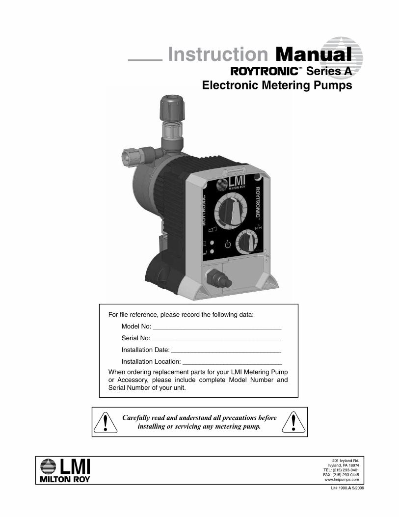
Lit# 1990.A 5/2009 201 Ivyland Rd. Ivyland, PA 18974 TEL: (215) 293-0401 FAX: (215) 293-0445 www.lmipumps.com Carefully read and understand all precautions before installing or servicing any metering pump. For file reference, please record the following data: Model No: _____________________________________ Serial No: _____________________________________ Installation Date: ________________________________ Installation Location: _____________________________ When ordering replacement parts for your LMI Metering Pump or Accessory, please include complete Model Number and Serial Number of your unit. Instruction Manual Series A Electronic Metering Pumps TM
The following precautions should be taken when working with LMI metering pumps. Please read this section carefully prior to installation.
Protective Clothing
ALWAYS wear protective clothing, face shield, safety glasses and gloves when working on or near your metering pump. Additional precautions should be taken depending on the solution being pumped. Refer to MSDS precautions from your solution supplier.
Water Pre-Prime
All LMI pumps are pre-primed with water when shipped from the factory. If your solu-tion is not compatible with water, disassemble the Pump Head Assembly. Thoroughly dry the pump head, valves, seal rings, balls and Liquifram™ (diaphragm). Reassemble head assembly tightening screws in a crisscross pattern. Refill the pump head with the solution to be pumped before priming the pump. (This will aid in priming.)
Liquid Compatibility
CAUTION: The evaluation performed by UL was tested with water only. LMI pumps are tested by NSF for use on muriatic acid and sodium hypochlorite. Determine if the materials of construction included in the liquid handling portion of your pump are adequate for the solution (chemical) to be pumped. Always refer to the solution supplier and the LMI Chemical Resistance Chart for compatibility of your specific LMI metering pump. Contact your local LMI distributor for further information.
Tubing Connections
Inlet and outlet tubing or pipe sizes must not be reduced. Outlet tubing size must not be increased. Make certain that all tubing is SECURELY ATTACHED to fittings prior to start-up (see Section 3.3, Tubing Connections). ALWAYS use LMI supplied tubing with your pump, as the tubing is specifically designed for use with the pump fittings. It is rec-ommended that all tubing be shielded and secure to prevent possible injury in case of rupture or accidental damage. If tubing is exposed to sunlight, black UV resistant tubing should be installed. Check tubing frequently for cracks and replace as necessary.
Vinyl Tubing
Your carton may contain a roll of clear vinyl tubing; this is only for connection to the return line of the FastPrime™ Head and must not be used as discharge tubing.
Fittings and Machine Threads
All fittings should be hand-tightened. An additional 1/8 - 1/4 turn after the fitting is snug may be necessary to provide a leak-proof seal. Excessive overtightening or use of a pipe wrench can cause damage to the fittings, seals, or pump head.
All LMI pumps have straight screw machine threads on the head and fittings and are sealed by the O-rings. DO NOT use Teflon® tape or pipe dope to seal threads. Teflon® Tape may only be used on the 1/2" NPT thread side of the Injection Check Valve, the stainless steel liquid end connections, or if piping is directly connected to the pipe threads of the suc-tion or discharge fittings.
5
PRECAUTIONS
Plumbing
Always adhere to your local plumbing codes and requirements. Be sure installation does not constitute a cross connection. Check local plumbing codes for guidelines. LMI is not responsible for improper installations.
Back Pressure/Anti-Syphon Valve
If you are pumping downhill or into low or no system pressure, a back pressure/anti-syphon device such as LMI’s Four-Function Valve should be installed to prevent over-pumping or syphoning. Contact your LMI distributor for furthur information.
Electrical Connections
WARNING: To reduce the risk of electrical shock, the metering pump must be plugged into a properly grounded grounding-type receptacle with ratings conforming to the data on the pump control panel. The pump must be connected to a good ground. Do not use adapters! All wiring must conform to local electrical codes. If the supply cord is damaged, it must be replaced by the manufacturer, stocking distributor, or authorized repair center in order to avoid a hazard.
Ground Fault Circuit Interrupter
WARNING: To reduce the risk of electric shock, install only on a circuit protected by a Ground Fault Circuit Interrupter (GFCI).
Line Depressurization
To reduce the risk of chemical splash during disassembly or maintenance, all installations should be equipped with line depressurization capability. Using LMI’s Four-Function Valve (4-FV) is one way to include this feature.
Over Pressure Protection
To ensure safe operation of the pump it is recommended that some type of safety/pres-sure-relief valve be installed to protect the piping and other system components from failing due to excessive pressure.
Chemical Concentration
There is a potential for elevated chemical concentration during periods of no flow, for example, during backwash in the system. Steps, such as turning the pump off, should be taken during operation or installation to prevent this.
See your distributor about other external control options to help mitigate this risk.
Retightening Components
Plastic materials will typically exhibit creep characteristics when under pressure over a period of time and to insure a proper fit it may be necessary to retighten the head bolts periodically. To insure proper operation, we recommend tightening the bolts to 25 inch-pounds after the first week of operation and on a monthly basis thereafter.
6
INTRODUCTION
2.0 Introduction
LMI is the world’s most versatile manufacturer of economical and efficient metering pumps. This manual addresses the installation, maintenance and troubleshooting proce-dures for manually and externally controlled pumps. LMI has a worldwide network of stocking representatives and authorized repair centers to give you prompt and efficient service.
Please review this manual carefully. Pay particular attention to warnings and precautions. Always follow good safety procedures, including the use of proper clothing, eye and face protection.
This manual is for Roytronic™ Series A pumps.
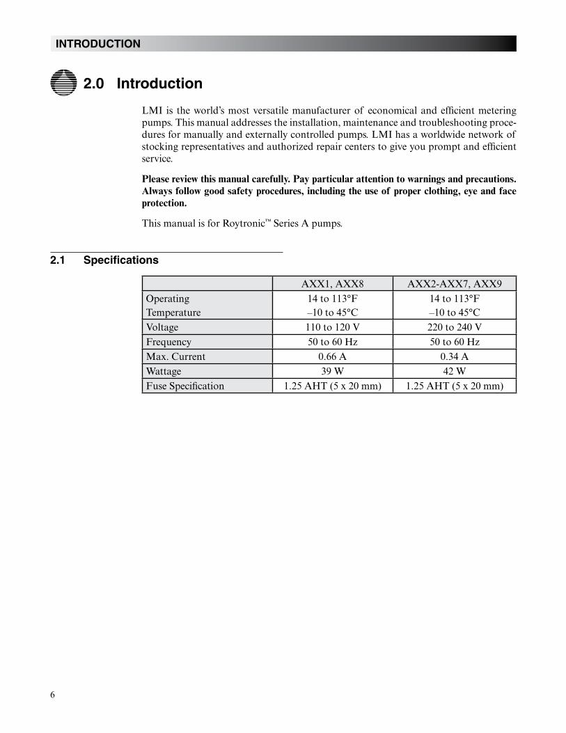
2.1 Specifications
AXX1, AXX8 AXX2-AXX7, AXX9Operating Temperature
14 to 113°F–10 to 45°C
14 to 113°F–10 to 45°C
Voltage 110 to 120 V 220 to 240 VFrequency 50 to 60 Hz 50 to 60 HzMax. Current 0.66 A 0.34 AWattage 39 W 42 WFuse Specification 1.25 AHT (5 x 20 mm) 1.25 AHT (5 x 20 mm)
7
UNPACKING CHECK LIST
2.2 Unpacking Check List
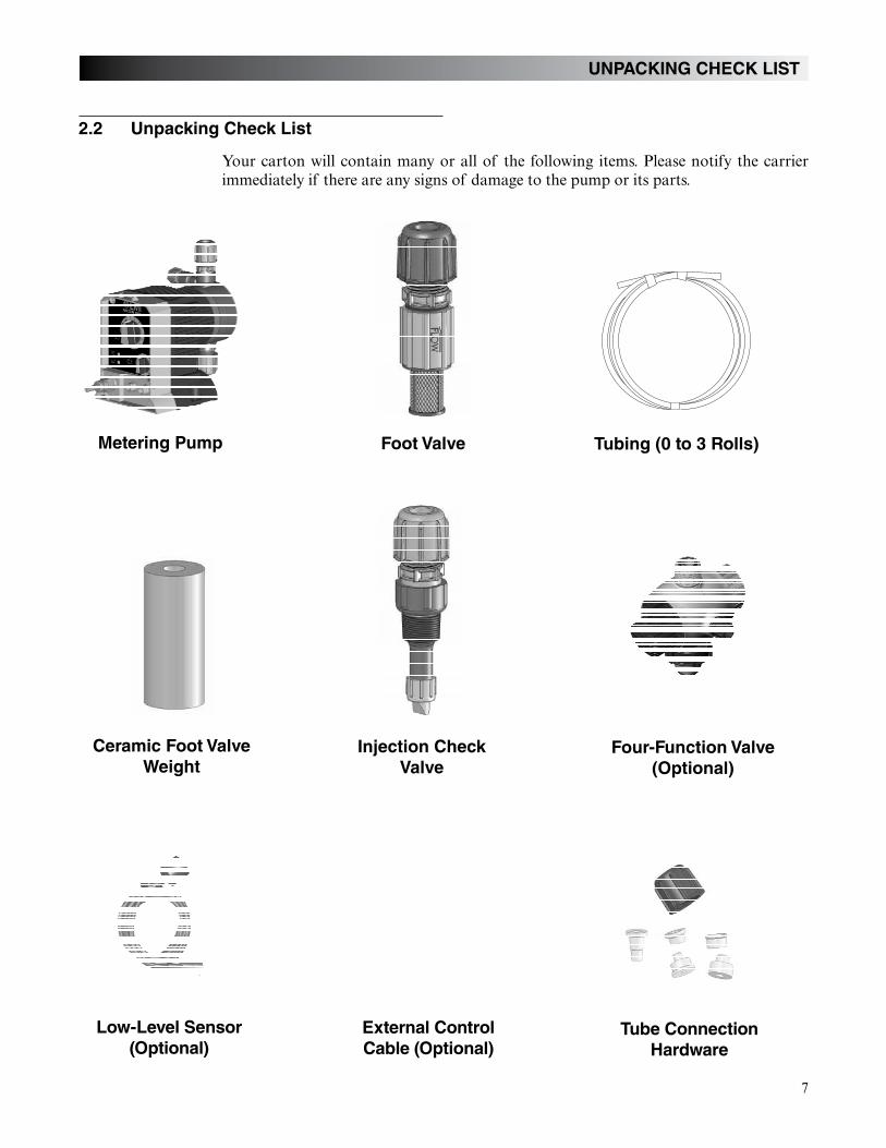
Your carton will contain many or all of the following items. Please notify the carrier immediately if there are any signs of damage to the pump or its parts.
Metering Pump Foot Valve Tubing (0 to 3 Rolls)
Ceramic Foot Valve
Weight
Injection Check
Valve
Four-Function Valve
(Optional)
Low-Level Sensor
(Optional)
External Control
Cable (Optional)
Tube Connection
Hardware
8
INSTALLATION
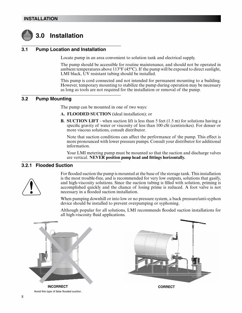
CORRECT
3.0 Installation
3.1 Pump Location and Installation
Locate pump in an area convenient to solution tank and electrical supply.
The pump should be accessible for routine maintenance, and should not be operated in ambient temperatures above 113°F (45°C). If the pump will be exposed to direct sunlight, LMI black, UV resistant tubing should be installed.
This pump is cord connected and not intended for permanent mounting to a building. However, temporary mounting to stabilize the pump during operation may be necessary as long as tools are not required for the installation or removal of the pump.
3.2 Pump Mounting
The pump can be mounted in one of two ways:
A. FLOODED SUCTION (ideal installation); or
B. SUCTION LIFT - when suction lift is less than 5 feet (1.5 m) for solutions having a specific gravity of water or viscosity of less than 100 cSt (centistokes). For denser or more viscous solutions, consult distributor.
Note that suction conditions can affect the performance of the pump. This effect is more pronounced with lower pressure pumps. Consult your distributor for additional information.
Your LMI metering pump must be mounted so that the suction and discharge valves are vertical. NEVER position pump head and fittings horizontally.
3.2.1 Flooded Suction
For flooded suction the pump is mounted at the base of the storage tank. This installation is the most trouble-free, and is recommended for very low outputs, solutions that gasify, and high-viscosity solutions. Since the suction tubing is filled with solution, priming is accomplished quickly and the chance of losing prime is reduced. A foot valve is not necessary in a flooded suction installation.
When pumping downhill or into low or no pressure system, a back pressure/anti-syphon device should be installed to prevent overpumping or syphoning.
Although popular for all solutions, LMI recommends flooded suction installations for all high-viscosity fluid applications.
INCORRECT
Avoid this type of false flooded suction.
9
INSTALLATION
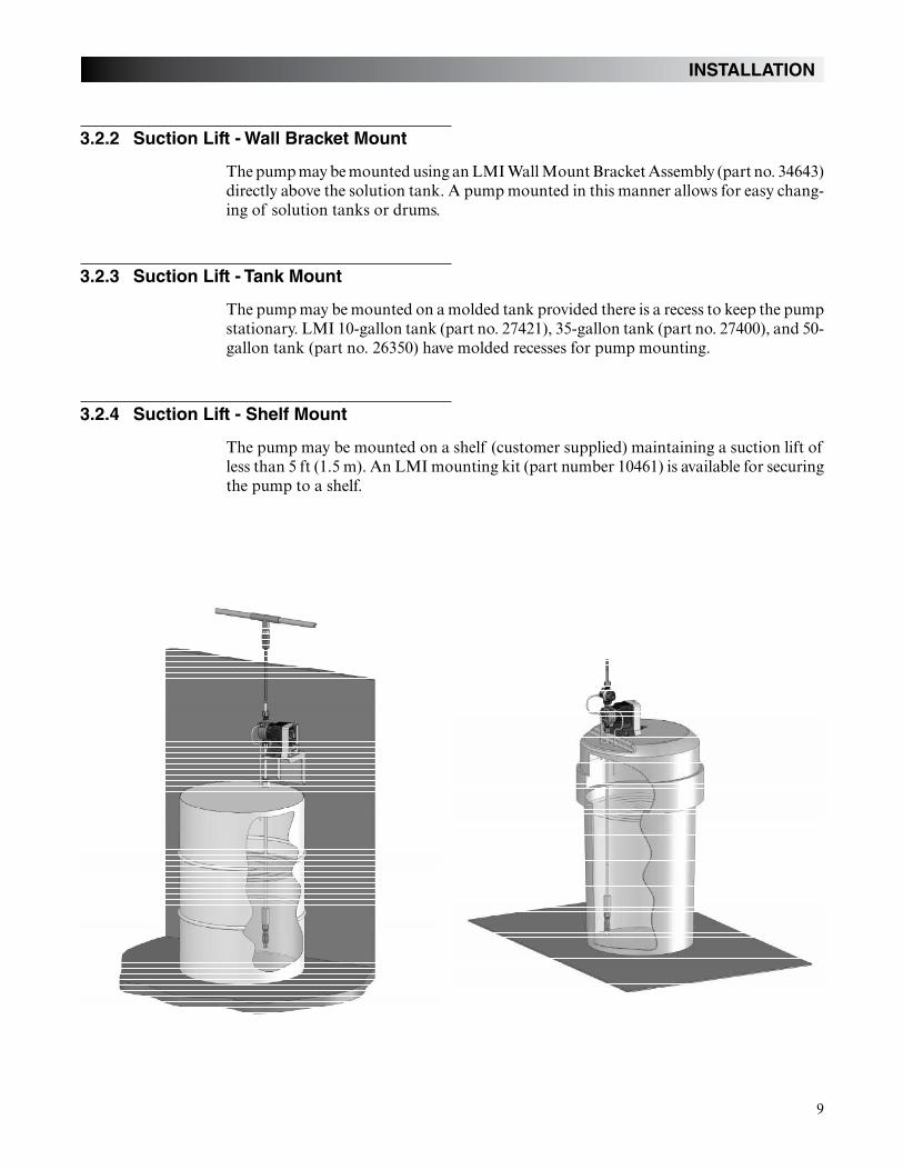
3.2.2 Suction Lift - Wall Bracket Mount
The pump may be mounted using an LMI Wall Mount Bracket Assembly (part no. 34643) directly above the solution tank. A pump mounted in this manner allows for easy chang-ing of solution tanks or drums.
3.2.3 Suction Lift - Tank Mount
The pump may be mounted on a molded tank provided there is a recess to keep the pump stationary. LMI 10-gallon tank (part no. 27421), 35-gallon tank (part no. 27400), and 50-gallon tank (part no. 26350) have molded recesses for pump mounting.
3.2.4 Suction Lift - Shelf Mount
The pump may be mounted on a shelf (customer supplied) maintaining a suction lift of less than 5 ft (1.5 m). An LMI mounting kit (part number 10461) is available for securing the pump to a shelf.
10
3.3 Tubing Connections
Use only LMI tubing.
DO NOT USE CLEAR VINYL TUBING ON THE DISCHARGE SIDE OF THE PUMP. The pressure created by the pump can rupture vinyl tubing, which is only forconnection to the return line of the FastPrime™ fitting.
Before installation, all tubing must be cut with a clean square end.
Valve and head connections from the factory are capped or plugged to retain pre-primewater. Remove and discard these caps or plugs before connecting tubing.
DO NOT USE PLIERS OR PIPE WRENCH ON COUPLING NUTS OR FITTINGS.
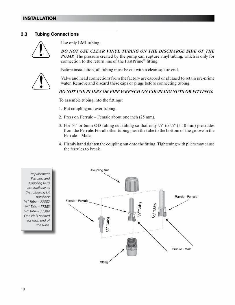
To assemble tubing into the fittings:
1. Put coupling nut over tubing.
2. Press on Ferrule – Female about one inch (25 mm).
3. For 1⁄1 4⁄⁄ " or 6mm OD tubing cut tubing so that only 1⁄1 4⁄⁄ " to 3⁄3 8⁄⁄ " (5-10 mm) protrudes from the Ferrule. For all other tubing push the tube to the bottom of the groove in theFerrule – Male.
4. Firmly hand tighten the coupling nut onto the fitting. Tightening with pliers may cause the ferrules to break.
ReplacementFerrules, and
Coupling Nuts are available as
the following kit numbers:
” Tube – 77382” Tube – 77383
” Tube – 77384One kit is needed
for each end of the tube.
Coupling Nut
rrule - Female
Fitting
Ferrule - Fem
ule - Male
11
INSTALLATION
3.4 Four-Function Valves (4-FV)
Your pump may be equipped with a 4-FV, or standard discharge valve. If your pump is not equipped with a four-function valve and you feel it is needed in your application, it can be purchased as an accessory. Contact your local LMI stocking distributor. The fea-tures of a 4-FV are listed below.
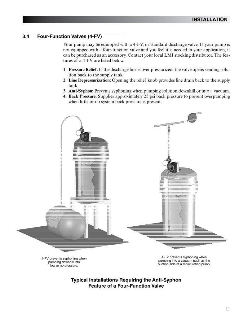
1. Pressure Relief: If the discharge line is over pressurized, the valve opens sending solu-tion back to the supply tank.
2. Line Depressurization: Opening the relief knob provides line drain back to the supply tank.
3. Anti-Syphon: Prevents syphoning when pumping solution downhill or into a vacuum.4. Back Pressure: Supplies approximately 25 psi back pressure to prevent overpumping
when little or no system back pressure is present.
Typical Installations Requiring the Anti-Syphon
Feature of a Four-Function Valve
4-FV prevents syphoning when pumping downhill into
low or no pressure.
4-FV prevents syphoning when pumping into a vacuum such as the suction side of a recirculating pump.
12
INSTALLATION
3.5 Four-Function Valve Installation
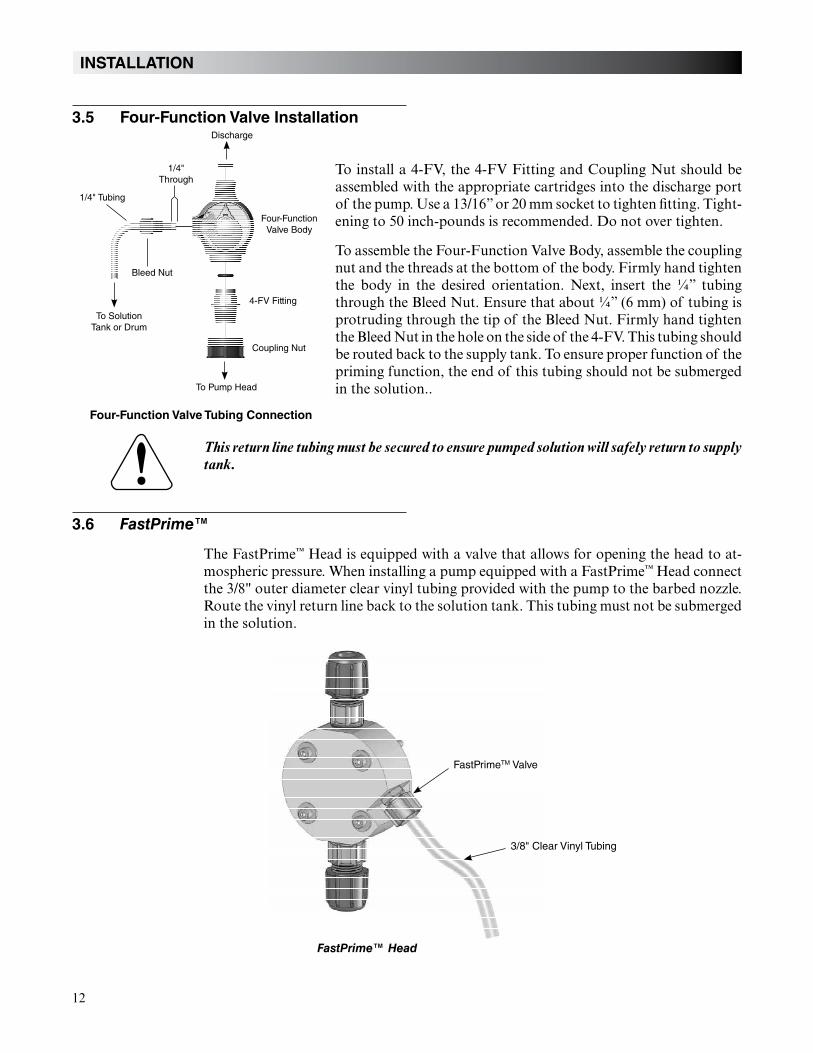
To install a 4-FV, the 4-FV Fitting and Coupling Nut should be assembled with the appropriate cartridges into the discharge port of the pump. Use a 13/16” or 20 mm socket to tighten fitting. Tight-ening to 50 inch-pounds is recommended. Do not over tighten.
To assemble the Four-Function Valve Body, assemble the coupling nut and the threads at the bottom of the body. Firmly hand tighten the body in the desired orientation. Next, insert the ¼” tubing through the Bleed Nut. Ensure that about ¼” (6 mm) of tubing is protruding through the tip of the Bleed Nut. Firmly hand tighten the Bleed Nut in the hole on the side of the 4-FV. This tubing should be routed back to the supply tank. To ensure proper function of the priming function, the end of this tubing should not be submerged in the solution..
This return line tubing must be secured to ensure pumped solution will safely return to supply tank.
3.6 FastPrime™
The FastPrime™ Head is equipped with a valve that allows for opening the head to at-mospheric pressure. When installing a pump equipped with a FastPrime™ Head connect the 3/8" outer diameter clear vinyl tubing provided with the pump to the barbed nozzle. Route the vinyl return line back to the solution tank. This tubing must not be submerged in the solution.
Four-Function Valve Tubing Connection
Discharge
1/4"Through
FastPrimeTM Valve
FastPrime™ Head
3/8" Clear Vinyl Tubing
1/4" Tubing
Four-FunctionValve Body
4-FV Fitting
Coupling Nut
To Pump Head
To SolutionTank or Drum
Bleed Nut
13
INSTALLATION
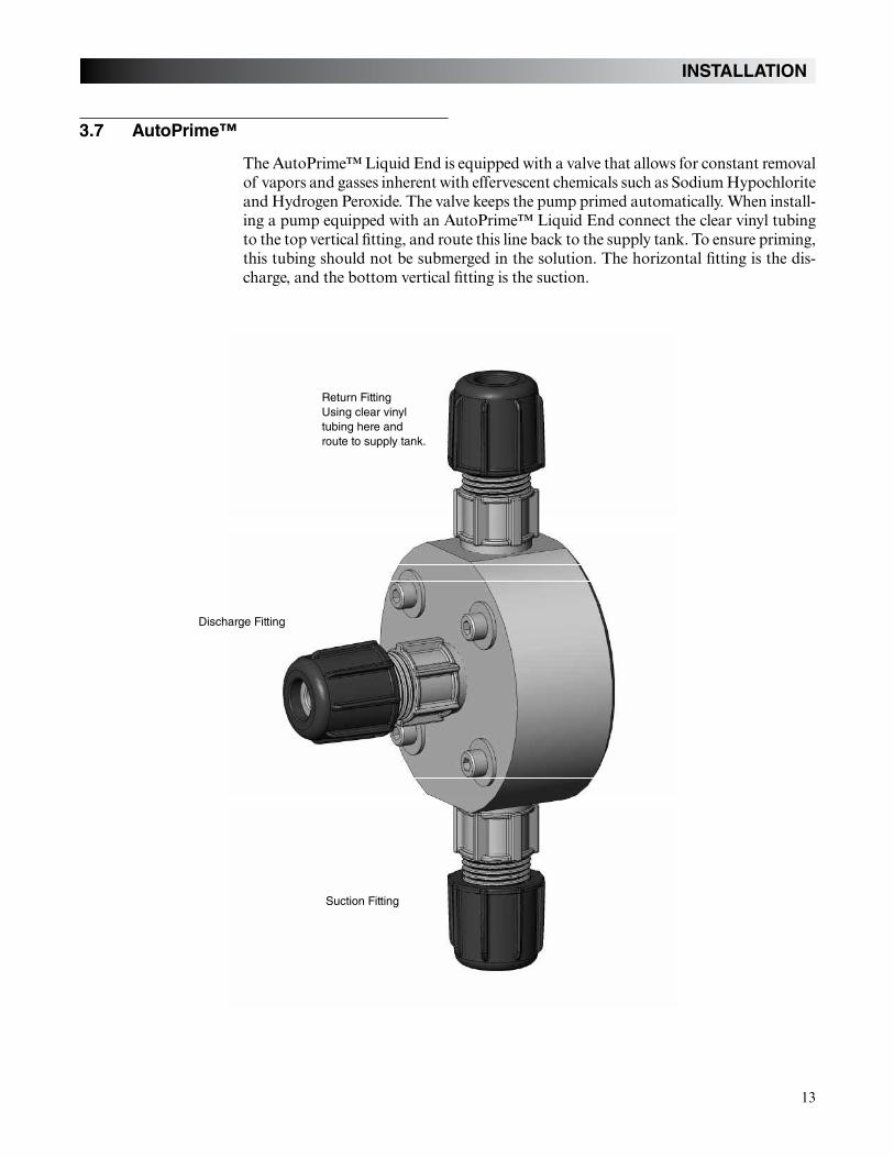
3.7 AutoPrime™
The AutoPrime™ Liquid End is equipped with a valve that allows for constant removal of vapors and gasses inherent with effervescent chemicals such as Sodium Hypochlorite and Hydrogen Peroxide. The valve keeps the pump primed automatically. When install-ing a pump equipped with an AutoPrime™ Liquid End connect the clear vinyl tubing to the top vertical fitting, and route this line back to the supply tank. To ensure priming, this tubing should not be submerged in the solution. The horizontal fitting is the dis-charge, and the bottom vertical fitting is the suction.
Return FittingUsing clear vinyl tubing here and route to supply tank.
Discharge Fitting
Suction Fitting
14
Us
fo
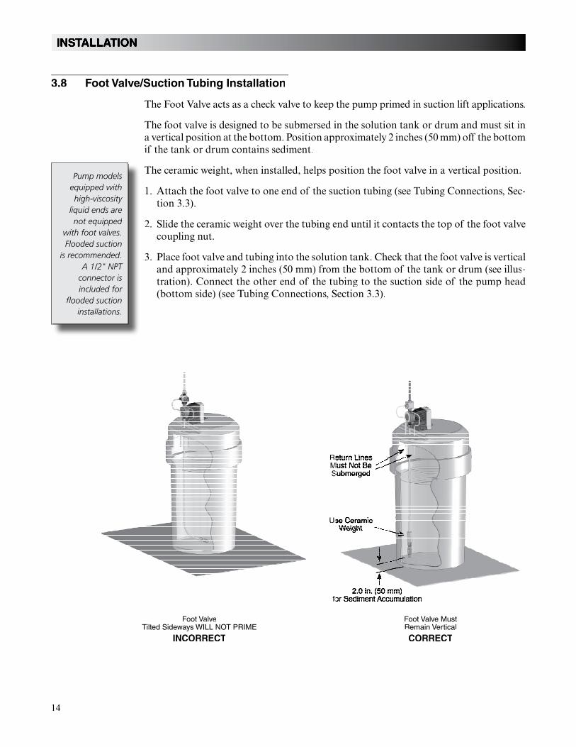
Foot ValveTilted Sideways WILL NOT PRIME
INCORRECT
Foot Valve MustRemain Vertical
CORRECT
3.8 Foot Valve/Suction Tubing Installation
The Foot Valve acts as a check valve to keep the pump primed in suction lift applications.
The foot valve is designed to be submersed in the solution tank or drum and must sit ina vertical position at the bottom. Position approximately 2 inches (50 mm) off the bottom if the tank or drum contains sediment.
The ceramic weight, when installed, helps position the foot valve in a vertical position.
1. Attach the foot valve to one end of the suction tubing (see Tubing Connections, Sec-tion 3.3).
2. Slide the ceramic weight over the tubing end until it contacts the top of the foot valve coupling nut.
3. Place foot valve and tubing into the solution tank. Check that the foot valve is vertical and approximately 2 inches (50 mm) from the bottom of the tank or drum (see illus-tration). Connect the other end of the tubing to the suction side of the pump head (bottom side) (see Tubing Connections, Section 3.3).
Pump models equipped with high-viscosity
liquid ends are not equipped
with foot valves. Flooded suction
is recommended. A 1/2" NPT
connector is included for
flooded suction installations.
ReMS
15
INSTALLATION
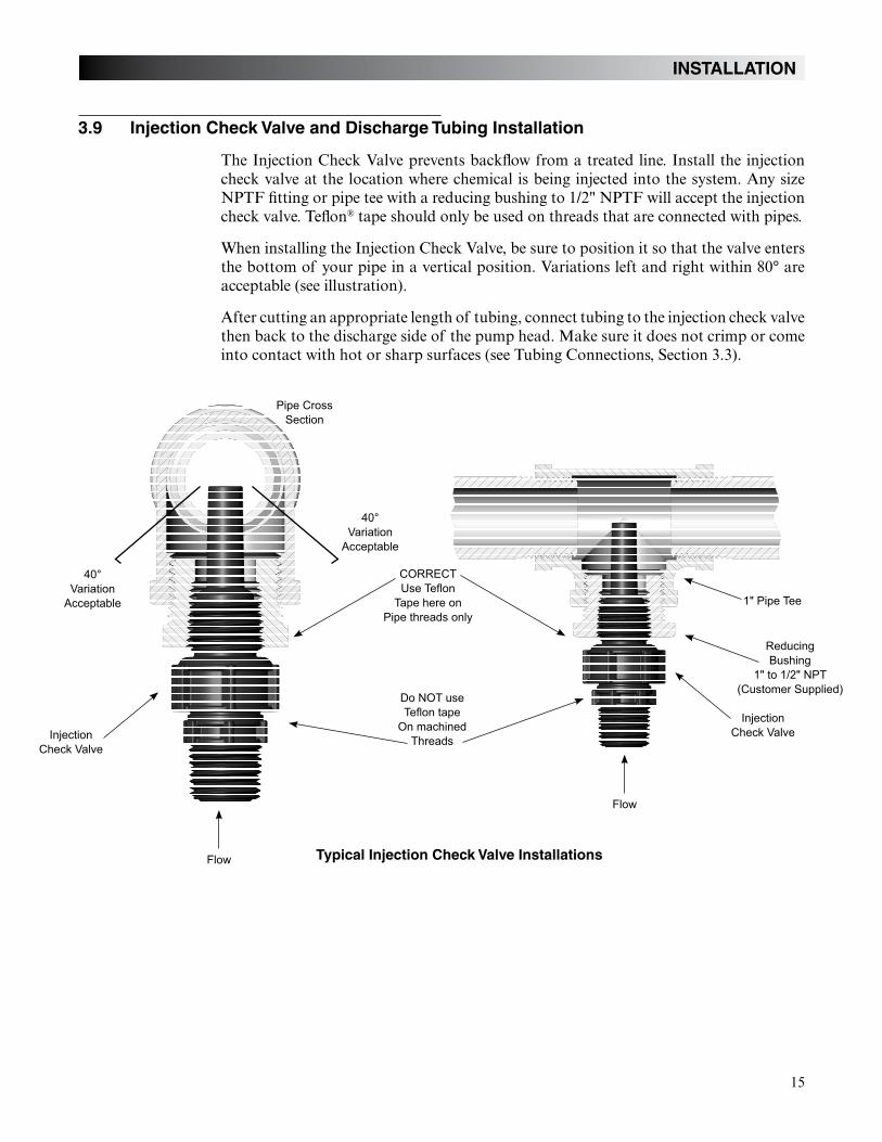
3.9 Injection Check Valve and Discharge Tubing Installation
The Injection Check Valve prevents backflow from a treated line. Install the injection check valve at the location where chemical is being injected into the system. Any size NPTF fitting or pipe tee with a reducing bushing to 1/2" NPTF will accept the injection check valve. Teflon® tape should only be used on threads that are connected with pipes.
When installing the Injection Check Valve, be sure to position it so that the valve enters the bottom of your pipe in a vertical position. Variations left and right within 80° are acceptable (see illustration).
After cutting an appropriate length of tubing, connect tubing to the injection check valve then back to the discharge side of the pump head. Make sure it does not crimp or come into contact with hot or sharp surfaces (see Tubing Connections, Section 3.3).
Typical Injection Check Valve Installations
1" Pipe Tee
Do NOT use
40° CORRECT
40°
16
OPERATION
4.0 Operation
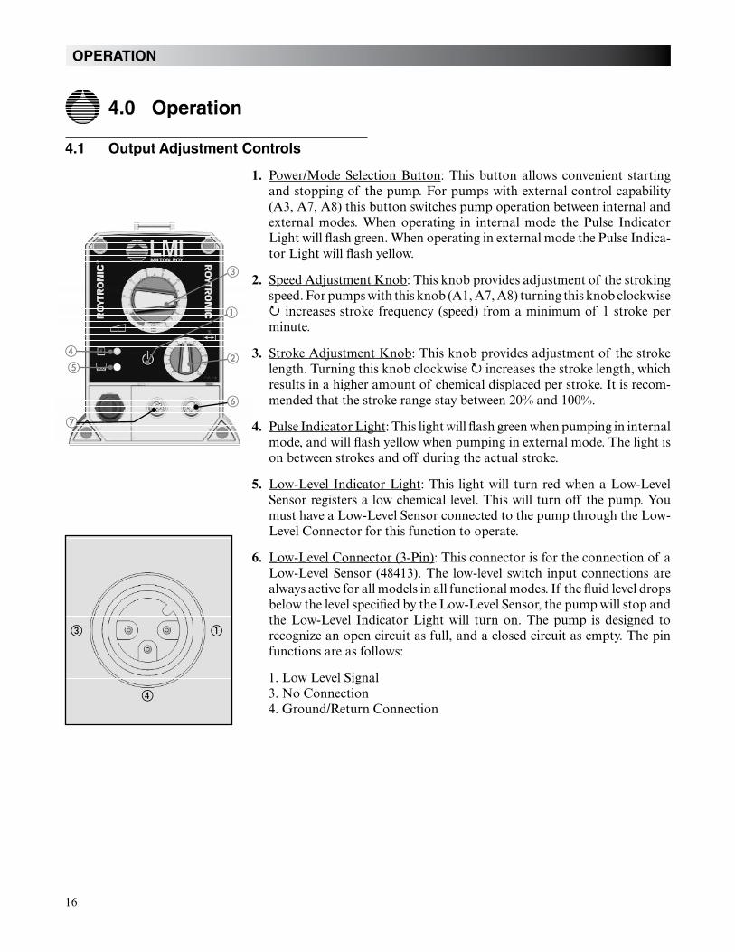
4.1 Output Adjustment Controls
1. Power/Mode Selection Button: This button allows convenient starting and stopping of the pump. For pumps with external control capability (A3, A7, A8) this button switches pump operation between internal and external modes. When operating in internal mode the Pulse Indicator Light will flash green. When operating in external mode the Pulse Indica-tor Light will flash yellow.
2. Speed Adjustment Knob: This knob provides adjustment of the stroking speed. For pumps with this knob (A1, A7, A8) turning this knob clockwise
increases stroke frequency (speed) from a minimum of 1 stroke per minute.
3. Stroke Adjustment Knob: This knob provides adjustment of the stroke length. Turning this knob clockwise increases the stroke length, which results in a higher amount of chemical displaced per stroke. It is recom-mended that the stroke range stay between 20% and 100%.
4. Pulse Indicator Light: This light will flash green when pumping in internal mode, and will flash yellow when pumping in external mode. The light is on between strokes and off during the actual stroke.
5. Low-Level Indicator Light: This light will turn red when a Low-Level Sensor registers a low chemical level. This will turn off the pump. You must have a Low-Level Sensor connected to the pump through the Low-Level Connector for this function to operate.
6. Low-Level Connector (3-Pin): This connector is for the connection of a Low-Level Sensor (48413). The low-level switch input connections are always active for all models in all functional modes. If the fluid level drops below the level specified by the Low-Level Sensor, the pump will stop and the Low-Level Indicator Light will turn on. The pump is designed to recognize an open circuit as full, and a closed circuit as empty. The pin functions are as follows:
1. Low Level Signal 3. No Connection 4. Ground/Return Connection
➂
➀
➁
➅
➃
➄
➆
➂ ➀
➃
17
OPERATION
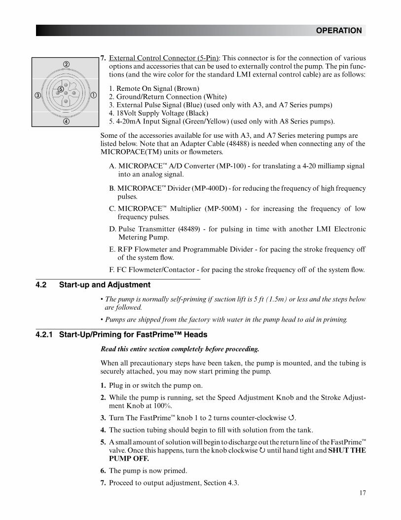
7. External Control Connector (5-Pin): This connector is for the connection of various options and accessories that can be used to externally control the pump. The pin func-tions (and the wire color for the standard LMI external control cable) are as follows:
1. Remote On Signal (Brown)2. Ground/Return Connection (White)3. External Pulse Signal (Blue) (used only with A3, and A7 Series pumps) 4. 18Volt Supply Voltage (Black)5. 4-20mA Input Signal (Green/Yellow) (used only with A8 Series pumps).
Some of the accessories available for use with A3, and A7 Series metering pumps are listed below. Note that an Adapter Cable (48488) is needed when connecting any of the MICROPACE(TM) units or flowmeters.
A. MICROPACE™ A/D Converter (MP-100) - for translating a 4-20 milliamp signal into an analog signal.
B. MICROPACE™ Divider (MP-400D) - for reducing the frequency of high frequency pulses.
C. MICROPACE™ Multiplier (MP-500M) - for increasing the frequency of low frequency pulses.
D. Pulse Transmitter (48489) - for pulsing in time with another LMI Electronic Metering Pump.
E. RFP Flowmeter and Programmable Divider - for pacing the stroke frequency off of the system flow.
F. FC Flowmeter/Contactor - for pacing the stroke frequency off of the system flow.
4.2 Start-up and Adjustment
4.2.1 Start-Up/Priming for FastPrime™ Heads
Read this entire section completely before proceeding.
When all precautionary steps have been taken, the pump is mounted, and the tubing is securely attached, you may now start priming the pump.
1. Plug in or switch the pump on.
2. While the pump is running, set the Speed Adjustment Knob and the Stroke Adjust-ment Knob at 100%.
3. Turn The FastPrime™ knob 1 to 2 turns counter-clockwise .
4. The suction tubing should begin to fill with solution from the tank.
5. A small amount of solution will begin to discharge out the return line of the FastPrime™
valve. Once this happens, turn the knob clockwise until hand tight and SHUT THE PUMP OFF.
6. The pump is now primed.
7. Proceed to output adjustment, Section 4.3.
➂ ➀
➃
➁
➄
18
4.2.2 Start-Up/Priming for Pump Supplied with 4-FV
Read this entire section completely before proceeding.
When all precautionary steps have been taken, the pump is mounted, and the tubing issecurely attached, you may now start priming the pump.
1. Plug in or switch the pump on.
2. While the pump is running, set the Speed Adjustment Knob and the Stroke Adjust-ment Knob at 100%.
3. Open the relief side (black knob) of the 4-FV by turning to the stop (about 1/8 turn).
4. The suction tubing should begin to fill with solution from the tank.
5. A small amount of solution will begin to discharge out the return line of the 4-FV.Once this happens, return the knob to the 12:00 position and SHUT THE PUMP OFF.
6. The pump is now primed.
7. Proceed to output adjustment, Section 4.3.
4.2.3 Start-Up/Priming Without 4-FV
Read this entire section completely before proceeding.
When all precautionary steps have been taken, the pump is mounted, and the tubing issecurely attached, you may prime the pump.
1. Plug in or switch on the pump.
2. While the pump is running, set the speed knob and the stroke knob at 100%.
3. The suction tubing should begin to fill with solution from the tank.
4. Once the solution begins to exit the pump head on the discharge side, SHUT THE PUMP OFF.
5. The pump is now primed.
6. Proceed to output adjustment, Section 4.3.
4.3 Output Adjustment
Once the pump has been primed, an appropriate output adjustment MUST be made. Pump output should be calculated and adjustments made accordingly.
If the pump does not self-prime,
remove the discharge check valve and pour
water or solution into the port until the head is filled.
Replace valve, then follow start
up/priming steps.
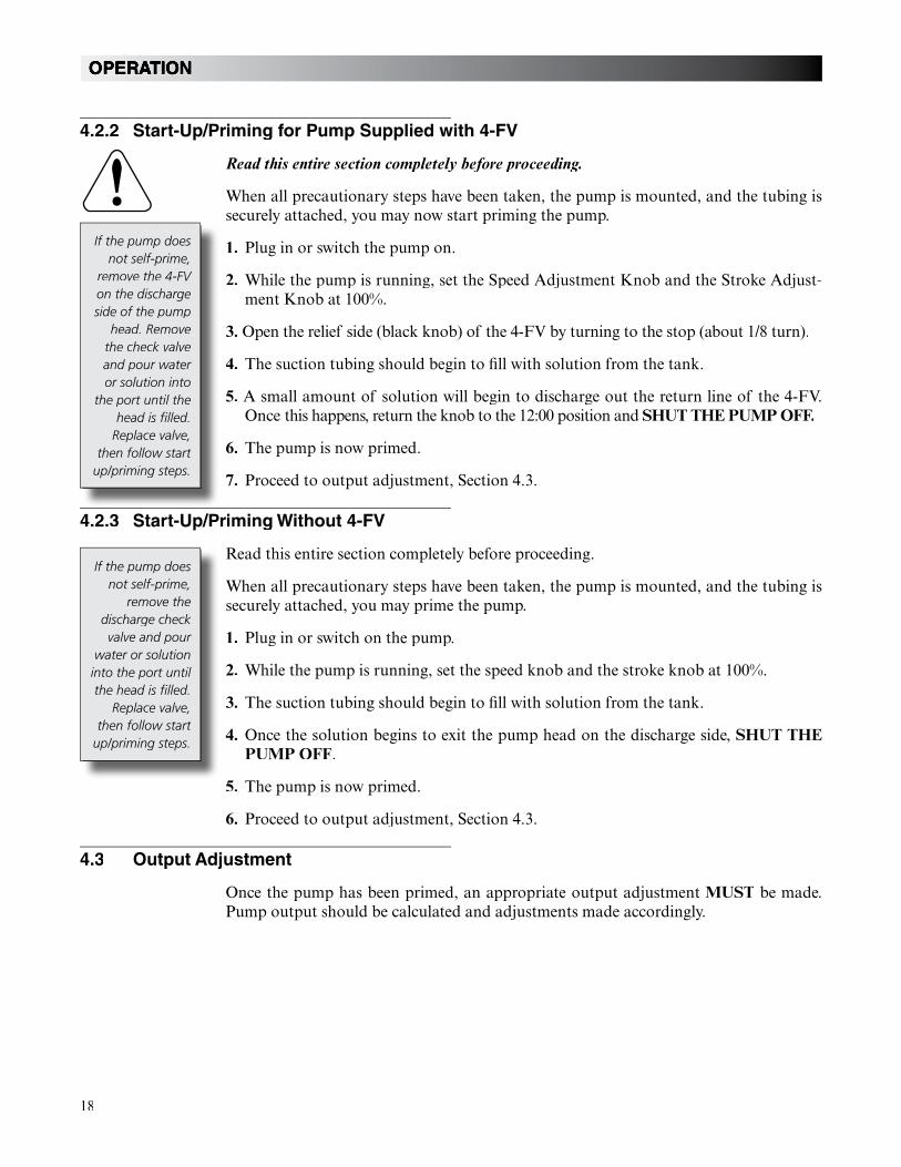
If the pump does not self-prime,
remove the 4-FV on the discharge side of the pump
head. Remove the check valve and pour water or solution into
the port until the head is filled.
Replace valve, then follow start
up/priming steps.
19
4.3.1 Total Pump Output
Calculate the approximate output of the pump as follows:
PUMP OUTPUT = MAX PUMP OUTPUT x % SPEED x % STROKE
Example: A151-928SI
Use Max Output (from dataplate on side of pump) = 1 GPH (1 gallon per hour).
If the pump is set at 60% speed and 70% stroke length, the approximate pump out-put is:
1.0 x 0.60 x 0.70 = 0.42 GPH.
Multiply by 24 (hours in one day) to calculate in gallons per day. If pump is not equipped with speed adjustment, calculate by Max Pump Output x % Stroke only.
4.3.2 Calibration in Internal Mode
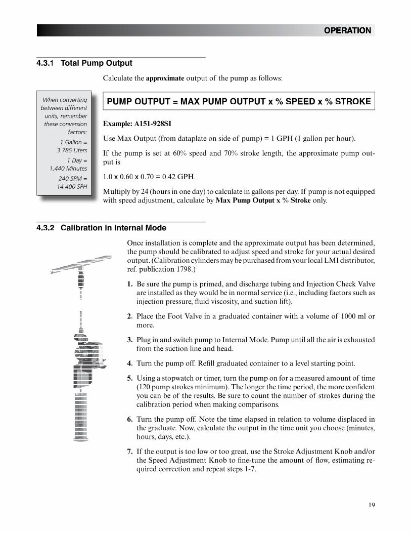
Once installation is complete and the approximate output has been determined,the pump should be calibrated to adjust speed and stroke for your actual desiredoutput. (Calibration cylinders may be purchased from your local LMI distributor, ref. publication 1798.)
1. Be sure the pump is primed, and discharge tubing and Injection Check Valve are installed as they would be in normal service (i.e., including factors such asinjection pressure, fluid viscosity, and suction lift).
2. Place the Foot Valve in a graduated container with a volume of 1000 ml or more.
3. Plug in and switch pump to Internal Mode. Pump until all the air is exhaustedfrom the suction line and head.
4. Turn the pump off. Refill graduated container to a level starting point.
5. Using a stopwatch or timer, turn the pump on for a measured amount of time(120 pump strokes minimum). The longer the time period, the more confident you can be of the results. Be sure to count the number of strokes during the calibration period when making comparisons.
6. Turn the pump off. Note the time elapsed in relation to volume displaced inthe graduate. Now, calculate the output in the time unit you choose (minutes, hours, days, etc.).
7. If the output is too low or too great, use the Stroke Adjustment Knob and/orthe Speed Adjustment Knob to fine-tune the amount of flow, estimating re-quired correction and repeat steps 1-7.
When converting between different
units, remember these conversion
factors:
1 Gallon =3.785 Liters
1 Day =1,440 Minutes
240 SPM = 14,400 SPH
20
4.3.3 Calibration in External Mode
1. Since pump output is governed by an external device such as Flowmeter-Pulser, Liquitron™ Controller, or 4-20 mA DC signal from an instrument with an LMI Analog-to-Digital Converter, only the output per stroke may be calibrated.
2. With pump primed and discharge tubing connected to the injection point as it would be in normal service, place Foot Valve Assembly in a graduated container with a vol-ume of 1000 ml or more.
3. Switch pump to Internal mode with Speed Adjustment Knob set at 100% until air isexhausted from suction line and pump head.
4. Switch pump OFF and refill graduate to a starting point.
5. Switch pump ON and count the number of strokes for exactly one minute, then switch pump OFF.
6. Note volume pumped during the calibration period of one minute. Divide into this the number of strokes to determine the volume of solution pumped per stroke.
Example: 720 ml in 240 strokes = 3.0 ml per stroke.
Multiply this by your expected stroke rate per minute, per hour or per day and compare with desired output requirements.
7. Turn Stroke Adjustment Knob to your best estimate of required correction and repeat calibration procedure.
It may be helpful to decrease
the speed of the pump in
order to count the number
of strokes. For accuracy count at least 120 strokes.
21
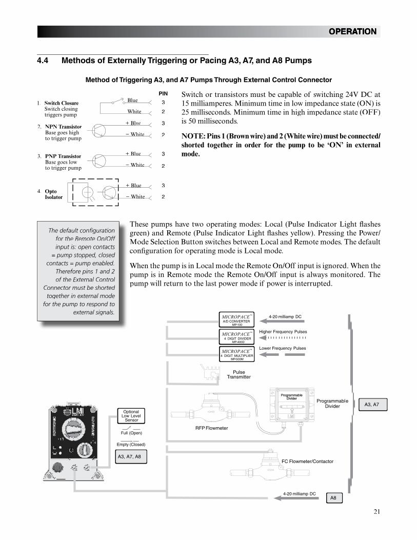
4.4 Methods of Externally Triggering or Pacing A3, A7, and A8 Pumps
Switch or transistors must be capable of switching 24V DC at15 milliamperes. Minimum time in low impedance state (ON) is 25 milliseconds. Minimum time in high impedance state (OFF)is 50 milliseconds.
NOTE: Pins 1 (Brown wire) and 2 (White wire) must be connected/shorted together in order for the pump to be ‘ON’ in external mode.
4. OptoIsolator
2. NPN TransistorBase goes highto trigger pump
White
3. PNP TransistorBase goes lowto trigger pump
Method of Triggering A3, and A7 Pumps Through External Control Connector
1. Switch ClosureSwitch closingtriggers pump
PIN
3
2
3
2
3
2
3
2
Blue
− White White
+ Blue
− WhiteWhite
+ Blue Blue
− WhiteWhite
+ Blue
Full (Open)
Empty (Closed)
4-20 milliamp DC
4-20 milliamp DC
Higher Frequency Pulses
Lower Frequency Pulses
PulseTransmitter
MICROPACE™
4 DIGIT DIVIDERMP-400D
MICROPACE™
A/D CONVERTER MP-100
MICROPACE™
4 DIGIT MULTIPLIERMP-500M
RFP Flowmeter
ProgrammableDivider
ProgrammableDivider
FC Flowmeter/ContactorA3, A7, A8
A3, A7
A8
OptionalLow Level
Sensor
The default configurationfor the Remote On/Off input is: open contacts
= pump stopped, closed contacts = pump enabled.
Therefore pins 1 and 2 of the External Control
Connector must be shorted together in external mode
for the pump to respond toexternal signals.
These pumps have two operating modes: Local (Pulse Indicator Light flashes green) and Remote (Pulse Indicator Light flashes yellow). Pressing the Power/Mode Selection Button switches between Local and Remote modes. The default configuration for operating mode is Local mode.
When the pump is in Local mode the Remote On/Off input is ignored. When thepump is in Remote mode the Remote On/Off input is always monitored. The pump will return to the last power mode if power is interrupted.
22
4.4.1 Control Modes
4.4.1.1 Local Mode
knob.
4.4.1.2 Remote Mode (for A3, and A7)
Pins 1 (brown wire) and 2 (white wire) must be connected/shorted together in order for the pump to respond to pulses in external mode.
than 50ms apart) and pulses with a duration of less than 25ms are ignored.
results in the pump running at 240 SPM.
4.4.1.3 Remote Mode (for A8)
Pins 1 (brown wire) and 2 (white wire) must be connected/shorted together in order for the pump to respond to a milliamp signal.
In Remote mode the pump speed is controlled by a milliamp (mA) Analog Input signal.The factory default settings for the Analog Input are: 20mA input = maximum speed, 4 mA = 0 strokes per minute. The mA input setting can be calibrated to any level between0 – 22 mA. When recalibrating the input settings, the span between high and low inputmust be greater than 6 mA. If the span is not large enough, the Pulse Indicator Light will flash green and yellow alternately at about 10 times per second.
In the default settings, the fast level mA input is greater than the slow level mA input.This is known as direct action. In direct action when the mA input is at or above the set-ting for the fast level, the pump will run at maximum speed. When the mA input is below the setting for the slow level, the pump will stop.
Reverse action is when the slow level mA input is greater than the fast level mA input. Inreverse action when the mA input is at or below the setting for the fast level, the pumpwill run at maximum speed. When the mA input is above the setting for the slow level, the pump will stop.
The default definition of a
pulse is: close = pulse starts, open
= pulse ends.
23
OPERATION
4.4.1.4 Calibrating the Analog Input Settings (for A8)
1. Press and hold the Power/Mode Selection Button for more than 5 seconds. This enters the calibration mode. Pumping will stop while in calibration mode.
2. Turn the Speed Adjustment Knob completely clockwise to enter the fast level analog input state. The Pulse Indicator Light will flash 1 second green ¼ second yellow.
3. Apply the desired fast level analog signal and press the Power/Mode Selection Button for less than 3 seconds. The Pulse Indicator Light will be green for 1 second before re-suming flashing to confirm storage of the setting.
4. Turn the Speed Adjustment Knob completely counter-clockwise to enter the slow level analog input state. The Pulse Indicator Light will flash 1 second yellow ¼ second green.
5. Apply the desired slow level analog signal and press the Power/Mode Selection Button for less than 3 seconds. The Pulse Indicator Light will be yellow for 1 second before resuming flashing to confirm storage of the setting.
6. To return the pump to the factory default settings turn the Speed Adjustment Knob to 50%. The Pulse Indicator Light should flash 1 second green, 1 second yellow. Then press the Power/Mode Selection Button.
7. To exit calibration mode press and hold the Power/Mode Selection Button for more than 3 seconds.
24
MAINTENANCE
5.0 Spare Parts Replacement and Routine Maintenance
LMI recommends replacing the elastomeric components of the pump on an annual basis. Refer to the LMI Metering Pump Price List for the proper Spare Parts Kit or RPM Pro Pac™ kit number or contact your local LMI stocking distributor.
5.1 Depressurizing the Discharge Line
(for Pumps Equipped with a 4-FV Only)
ALWAYS wear protective clothing, face shield, safety glasses and gloves when performing any maintenance or replacement on your pump.
To reduce the risk of chemical splash during disassembly or maintenance, all installations should be equipped with line depressurization capability. Using LMI’s Four-Function Valve (4-FV) is one way to include this feature.
Read steps 1 and 2 below before proceeding.
1. Be sure the Injection Check Valve is properly installed and is operating. If a shut off valve has been installed downstream of the Injection Valve, it should be closed.
Be sure your relief tubing is connected to your 4-FV and runs back to your solution drum or tank.
2. Turn the black knob on the 4-FV 1/8 turn to the stop. Turn and hold the yellow knob for a few seconds. The discharge line is now depressurized. Keep both valve knobs open until solution drains back down the discharge tubing into the solution tank or drum. Then release the yellow knob, and turn the black knob to its normal position.
5.2 Depressurizing the Discharge Line
(for Single-Ball FastPrime™ Heads Only)
ALWAYS wear protective clothing, face shield, safety glasses and gloves when performing any maintenance or replacement on your pump.
Read steps 1 and 2 below before proceeding.
1. Be sure the Injection Check Valve is properly installed and is operating. If a shut off valve has been installed downstream of the Injection Valve, it should be closed.
Be sure your relief tubing is connected to your FastPrime™ valve and runs back to your solu-tion drum or tank.
2. Turn the FastPrime™ knob one-and-a-half turns counter-clockwise . The discharge line is now depressurized. Keep valve open until solution drains back down the dis-charge tubing into solution drum or tank. Then turn the knob clockwise to tighten knob to closed position.
25
MAINTENANCE
5.3 Liquifram™ (Diaphragm) Replacement
ALWAYS wear protective clothing, face shield, safety glasses and gloves when working near or performing any maintenance or replacement on your pump. See MSDS information from solution supplier for additional precautions.
LMI metering pumps are designed for trouble-free operation, yet routine maintenance of elastomeric parts is essential for optimum performance. This involves replacing the Liquifram™, cartridge valves, O-rings, 4-FV cap assemblies and the injection check valve spring. LMI recommends replacing these parts at least once a year; however, frequency will depend on your particular application.
When replacing the Liquifram™, the cartridge valves, or O-rings, the injection check valve spring should also be replaced (see next Section 5.4). A Spare Parts Kit or RPM Pro Pac™
kit containing these parts may be obtained from your local distributor.
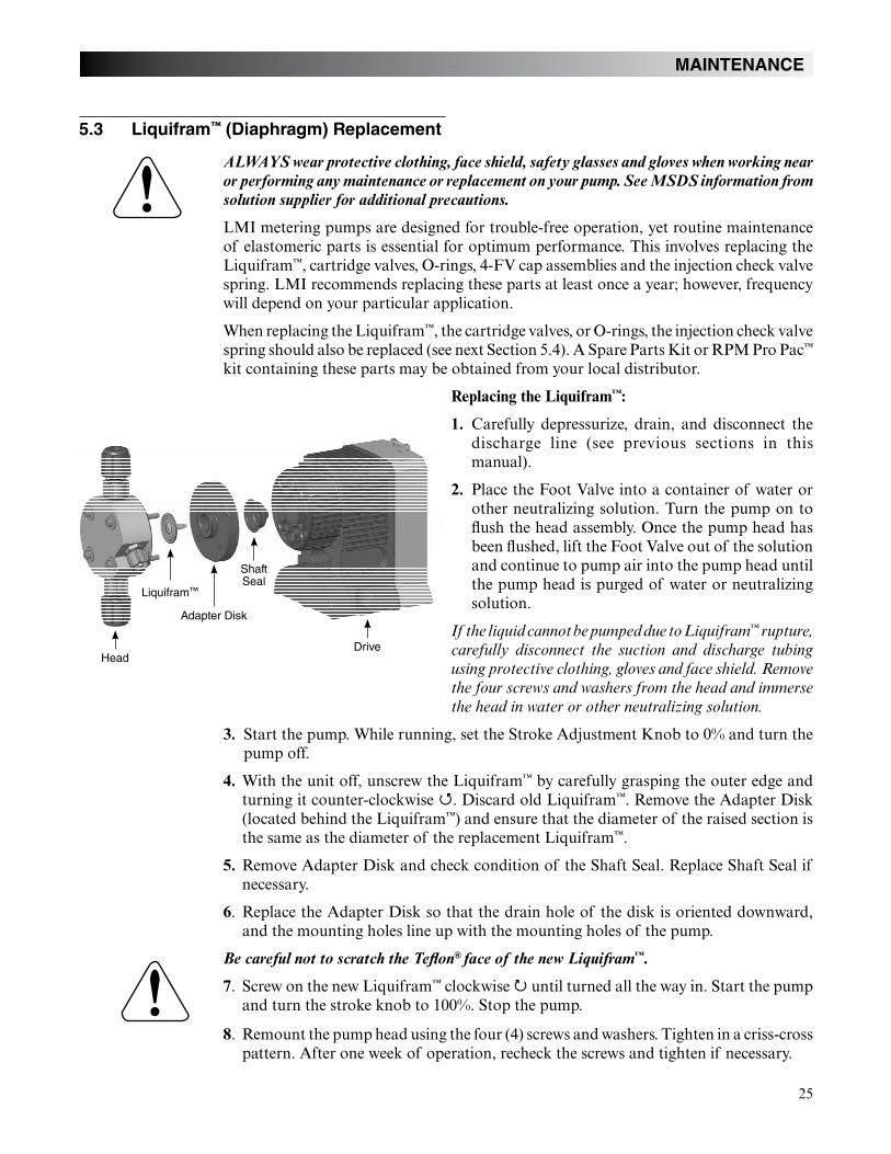
Replacing the Liquifram™:
1. Carefully depressurize, drain, and disconnect the discharge line (see previous sections in this manual).
2. Place the Foot Valve into a container of water or other neutralizing solution. Turn the pump on to flush the head assembly. Once the pump head has been flushed, lift the Foot Valve out of the solution and continue to pump air into the pump head until the pump head is purged of water or neutralizing solution.
™
3. Start the pump. While running, set the Stroke Adjustment Knob to 0% and turn the pump off.
4. With the unit off, unscrew the Liquifram™ by carefully grasping the outer edge and turning it counter-clockwise . Discard old Liquifram™. Remove the Adapter Disk (located behind the Liquifram™) and ensure that the diameter of the raised section is the same as the diameter of the replacement Liquifram™.
5. Remove Adapter Disk and check condition of the Shaft Seal. Replace Shaft Seal if necessary.
6. Replace the Adapter Disk so that the drain hole of the disk is oriented downward, and the mounting holes line up with the mounting holes of the pump.
Be careful not to scratch the Teflon® face of the new Liquifram™.
7. Screw on the new Liquifram™ clockwise until turned all the way in. Start the pump and turn the stroke knob to 100%. Stop the pump.
8. Remount the pump head using the four (4) screws and washers. Tighten in a criss-cross pattern. After one week of operation, recheck the screws and tighten if necessary.
HeadDrive
Liquifram™
Adapter Disk
Shaft Seal
26
MAINTENANCE
5.4 Cartridge Valve and O-ring Replacement
ALWAYS wear protective clothing, face shield, safety glasses and gloves when working on or performing any maintenance or replacement on your pump. See MSDS information from solution supplier for additional precautions.
Refer to the LMI Metering Pump Price List for the proper Spare Parts Kit or RPM Pro Pac™ kit number or contact your local LMI stocking distributor.
1. Carefully depressurize and disconnect the discharge line (see Section 5.1 or 5.2 in this manual).
2. Place the Foot Valve into a container of water or other neutralizing solution. Turn the pump on to flush the head assembly. Once the pump has been flushed, lift the Foot Valve out and continue to pump to let air into the pump head until pump is purged of water or neutralizing solution.
™
Spare part replacement kits include specific instructions for valve replacement. Please follow the instructions included with the replacement kit.
3. Carefully disconnect one tubing connection and fitting at a time, then remove and re-place the worn valve and O-rings. If necessary, carefully loosen stuck valves by prying side to side using a small screwdriver through the center hole of the valve.
Before disassembling the check valves, note the orientation of the valve.
4. Install new check valves in each location. Ensure that the cartridges are oriented correctly.
27
MAINTENANCE
5.5 Injection Check Valve Parts Replacement
Depressurize and drain pipeline (or isolate Injection Check Valve point using valves) so that Injection Check Valve can safely be disassembled.
ALWAYS wear protective clothing, face shield, safety glasses and gloves when working near or performing any maintenance or replacement on your pump. See MSDS information from solution supplier for additional precautions.
Refer to the LMI Metering Pump Price List for the proper Spare Parts Kit or RPM Pro Pac™ kit number or contact your local LMI stocking distributor.
1. Isolate Injection Check Valve and depressurize pipe or drain pipeline.
2. Carefully depressurize and disconnect the discharge line (see Section 5.1 or 5.2 in this manual).
Spare part replacement kits include specific instructions for valve replacement. Please follow the instructions included with the replacement kit.
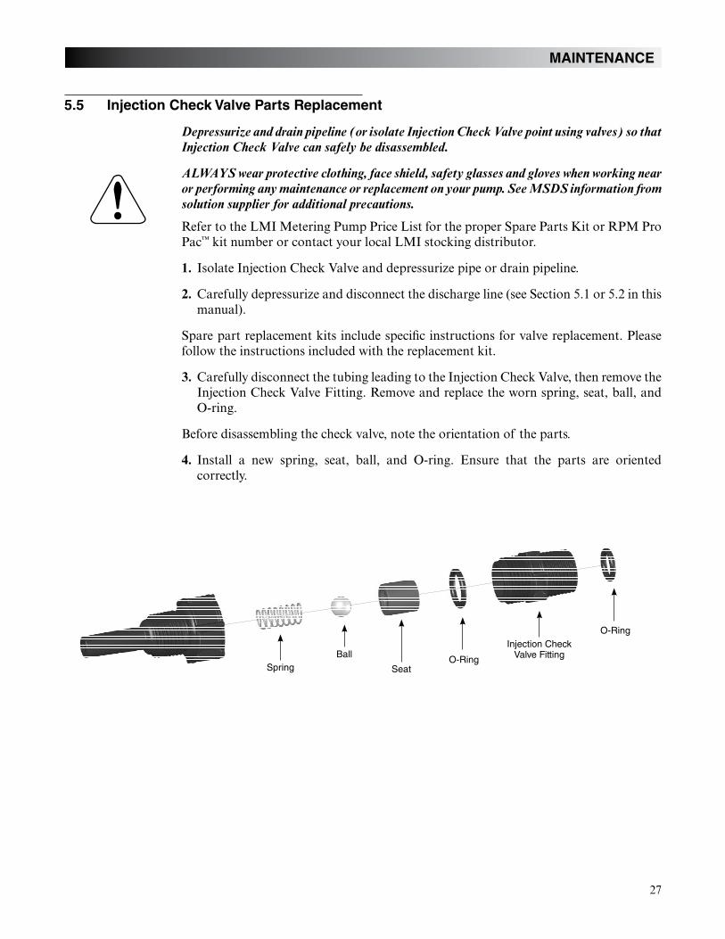
3. Carefully disconnect the tubing leading to the Injection Check Valve, then remove the Injection Check Valve Fitting. Remove and replace the worn spring, seat, ball, and O-ring.
Before disassembling the check valve, note the orientation of the parts.
4. Install a new spring, seat, ball, and O-ring. Ensure that the parts are oriented correctly.
SpringBall
Injection Check Valve Fitting
SeatO-Ring
O-Ring
28
MAINTENANCE
5.6 FastPrime™ Valve O-Ring Replacement
ALWAYS wear protective clothing, face shield, safety glasses and gloves when performing any maintenance or replacement on your pump.
Refer to the LMI Metering Pump Price List for the proper Spare Parts Kit or RPM Pro Pac™ kit number or contact your local LMI stocking distributor.
1. Be sure the Injection Check Valve is properly installed and is operating. If a shut off valve has been installed downstream of the Injection Valve, it should be closed.
Be sure your relief tubing is connected to your FastPrime™ valve and runs back to your solu-tion drum or tank.
2. Turn the FastPrime™ Knob one-and-a-half turns counter-clockwise . This will de-pressurize the head. Keep valve open. Carefully remove the return line by gently pulling tubing and moving it from side to side to gradually back tubing off of the barbed fitting.
3. Hold return line tubing upright until solution drains back into solution drum or tank.
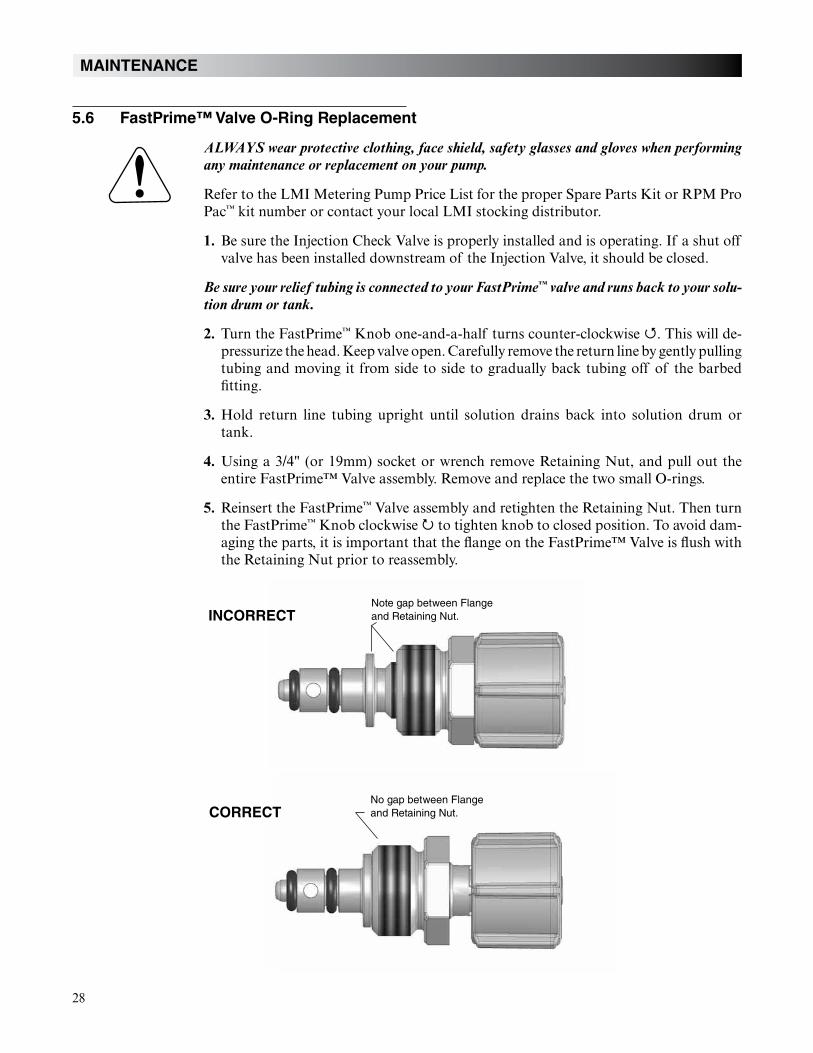
4. Using a 3/4" (or 19mm) socket or wrench remove Retaining Nut, and pull out the entire FastPrime™ Valve assembly. Remove and replace the two small O-rings.
5. Reinsert the FastPrime™ Valve assembly and retighten the Retaining Nut. Then turn the FastPrime™ Knob clockwise to tighten knob to closed position. To avoid dam-aging the parts, it is important that the flange on the FastPrime™ Valve is flush with the Retaining Nut prior to reassembly.
Note gap between Flangeand Retaining Nut.INCORRECT
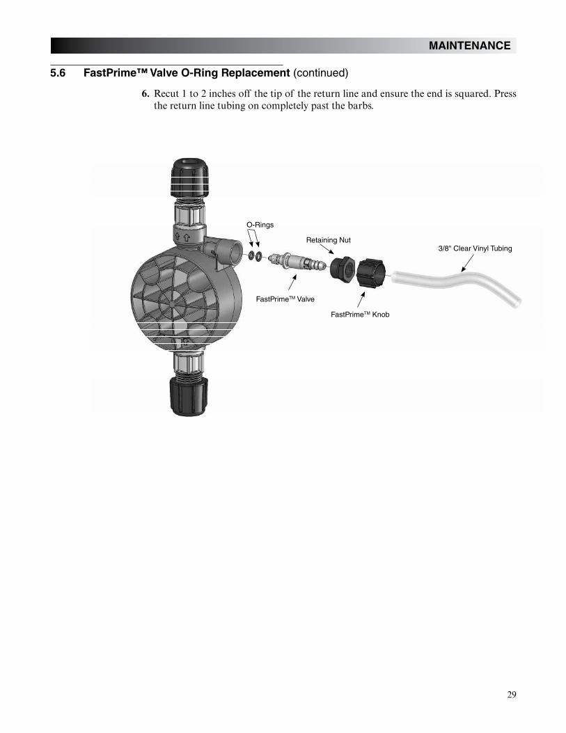
6. Recut 1 to 2 inches off the tip of the return line and ensure the end is squared. Press the return line tubing on completely past the barbs.
FastPrimeTM Knob
30
MAINTENANCE
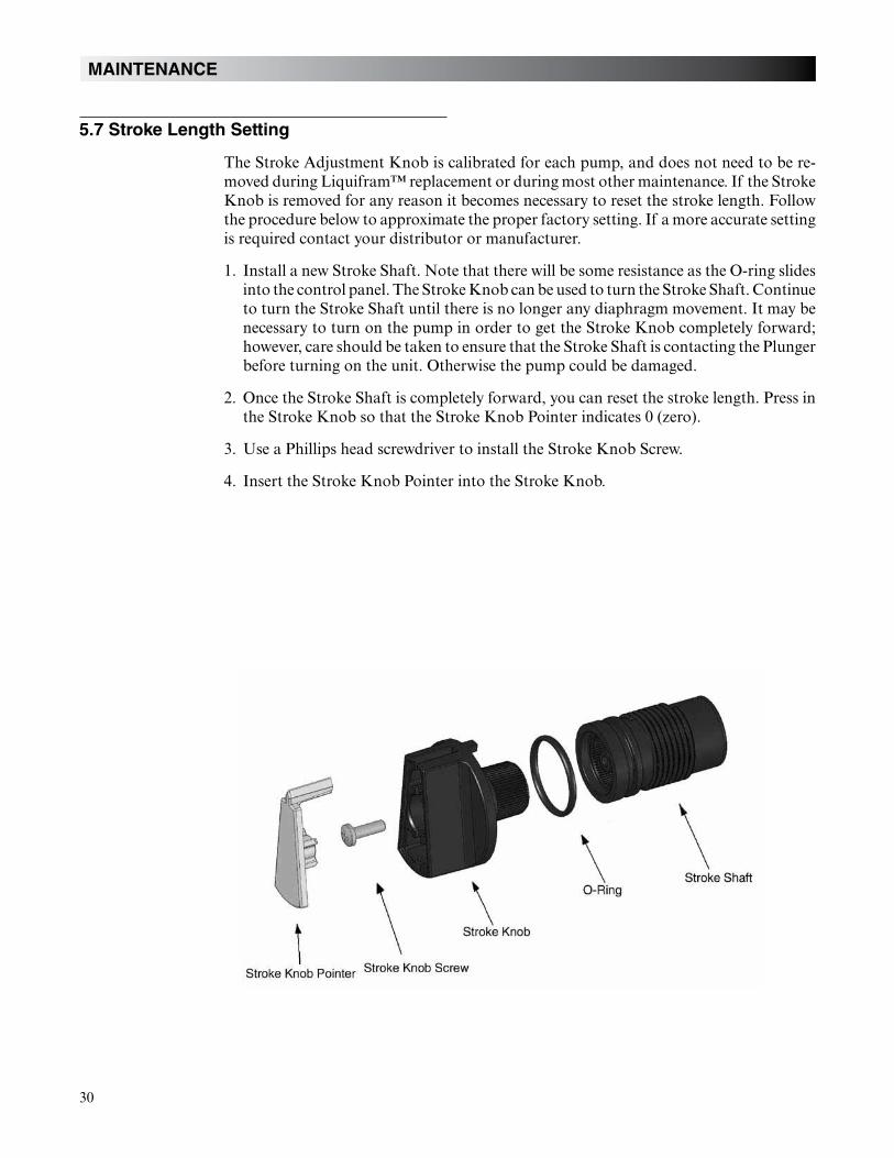
5.7 Stroke Length Setting
The Stroke Adjustment Knob is calibrated for each pump, and does not need to be re-moved during Liquifram™ replacement or during most other maintenance. If the Stroke Knob is removed for any reason it becomes necessary to reset the stroke length. Follow the procedure below to approximate the proper factory setting. If a more accurate setting is required contact your distributor or manufacturer.
1. Install a new Stroke Shaft. Note that there will be some resistance as the O-ring slides into the control panel. The Stroke Knob can be used to turn the Stroke Shaft. Continue to turn the Stroke Shaft until there is no longer any diaphragm movement. It may be necessary to turn on the pump in order to get the Stroke Knob completely forward; however, care should be taken to ensure that the Stroke Shaft is contacting the Plunger before turning on the unit. Otherwise the pump could be damaged.
2. Once the Stroke Shaft is completely forward, you can reset the stroke length. Press in the Stroke Knob so that the Stroke Knob Pointer indicates 0 (zero).
3. Use a Phillips head screwdriver to install the Stroke Knob Screw.
4. Insert the Stroke Knob Pointer into the Stroke Knob.
31
MAINTENANCE
Bubble
NumberDescription
Bubble
NumberDescription
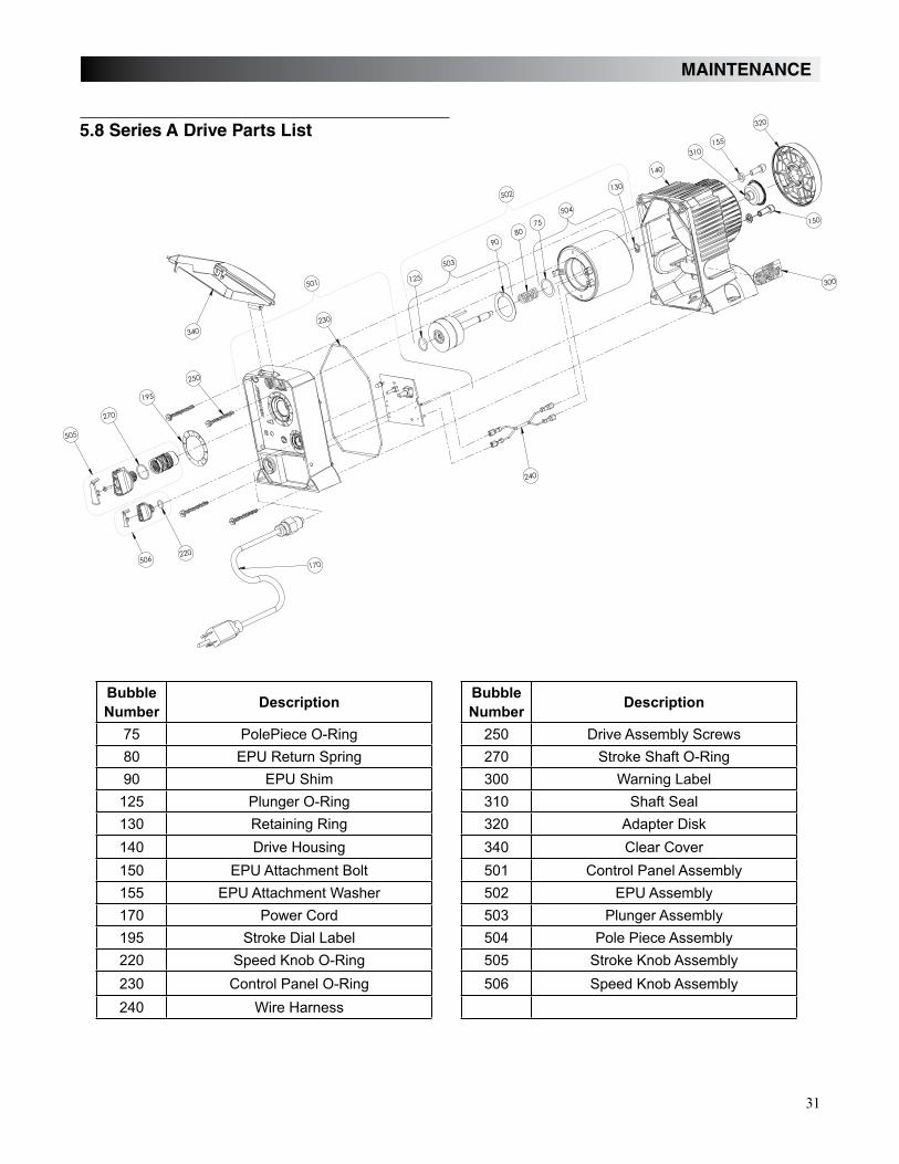
75
80
90 300
310
130
140 340
150 501
155
170 503
195 504
505
506
5.8 Series A Drive Parts List
140
300
130
8090
340
220
270
230
505
502
506
310
501
240
320
250
155
150
195
170
125
75
503
504
32
MAINTENANCE
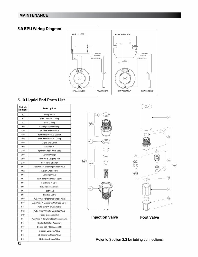
5.9 EPU Wiring Diagram
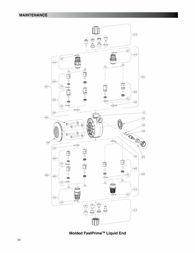
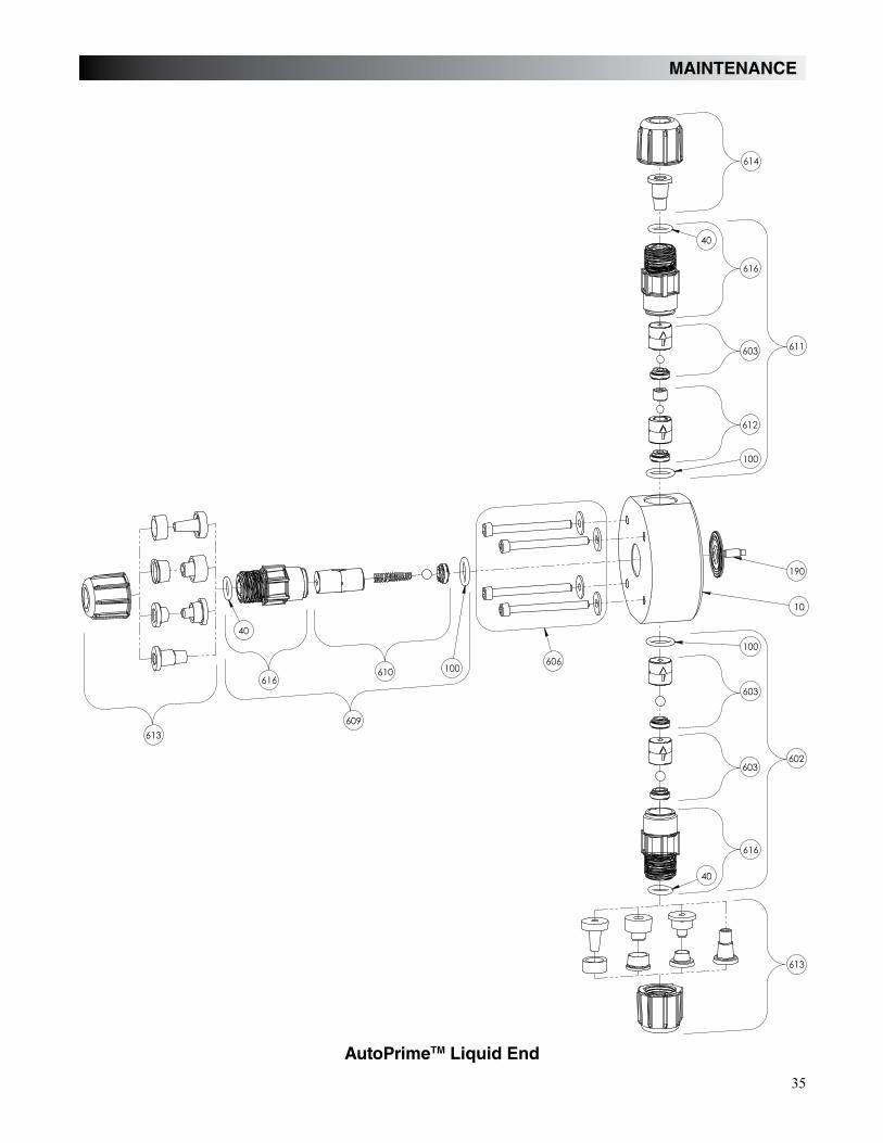
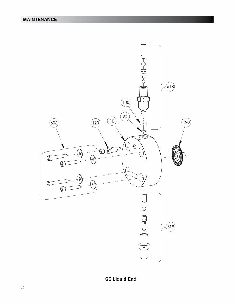
5.10 Liquid End Parts List
Injection Valve
BubbleNumber
Description
10
40
90
100
140
150
180
190
601
603
604
605
606
607
608
609
610
611
613*
614
615
616
617
618
619
A3/A7/A8 PULSERA0/A1 PULSER
EPU ASSEMBLYEPU ASSEMBLY POWER CORDPOWER CORD
BLK OR BRN
WHT OR BLU
GRN OR GRN/YEL
WHT OR BLU
BLK OR BRN
GRN OR GRN/YEL
YEL
YEL
YEL
YEL
P1
P2
P3
P2
P1
P3P4
P4
615
608617
40
100
230
607
603
615
40
250
100
270
260
90
A.
B.
Foot Valve
Refer to Section 3.3 for tubing connections.
33
MAINTENANCE
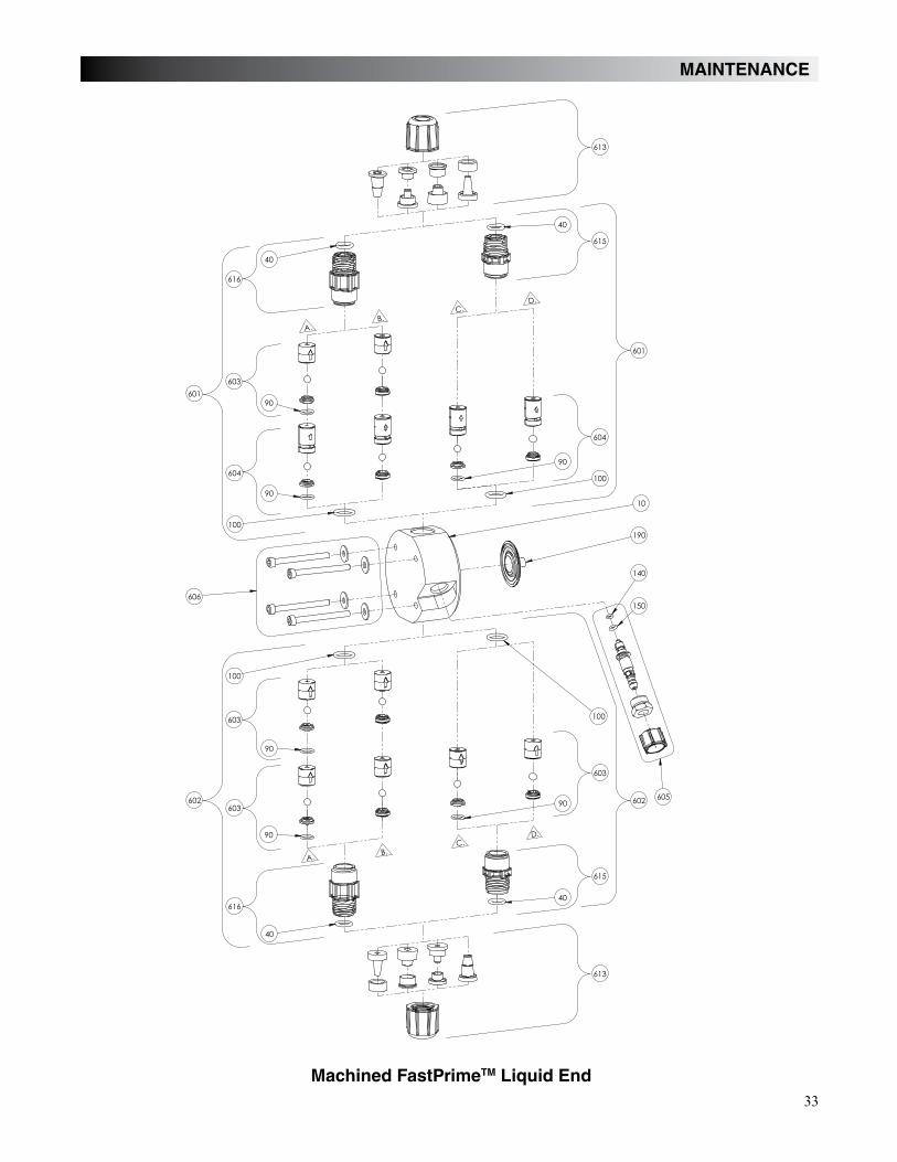
Machined FastPrimeTM Liquid End
190
100
90
100
90
90
100
90
A.B.
C.D.
C.D.
B.A.
150
140
90
606
10
605
90
604
601
603
604
601
603
602602
603
603
616
613
615
613
615
616
100
40
40
40
40
34
MAINTENANCE
Molded FastPrimeTM Liquid End
190
100
90
90
90
100
90
A.B.
C.D.
C.D.
B.A.
150
140
90
606
605
90
604
601
603
604
601
603
602602
603
603
616
613
615
613
615
616
100
40
40
40
40
100
10
180
35
MAINTENANCE
606
190
40
40
40
10
611
602
612
609
603
603
100
603
610 100
100
616
616
613
614
616
613
AutoPrimeTM Liquid End
36
MAINTENANCE
618
619
606 120 10 190
100
90
SS Liquid End
37
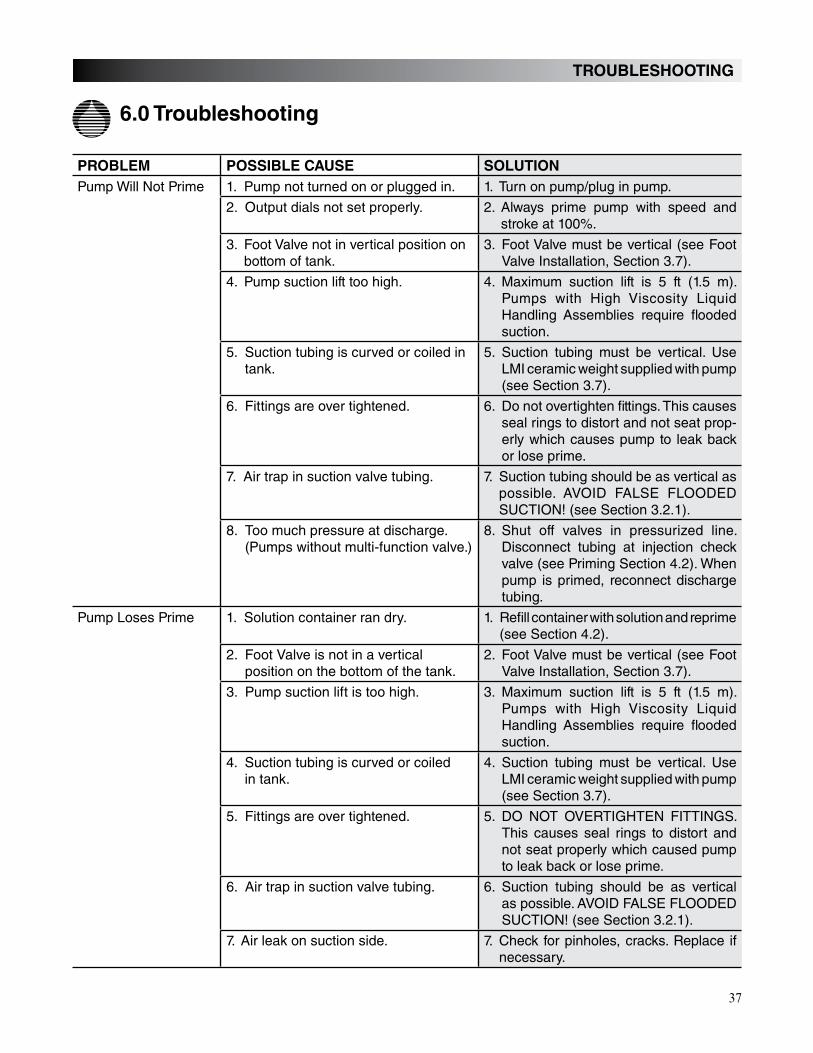
PROBLEM POSSIBLE CAUSE SOLUTION
Pump Will Not Prime 1. Pump not turned on or plugged in. 1. Turn on pump/plug in pump.
2. Output dials not set properly. 2. Always prime pump with speed and stroke at 100%.
3. Foot Valve not in vertical position on bottom of tank.
3. Foot Valve must be vertical (see Foot Valve Installation, Section 3.7).
4. Pump suction lift too high. 4. Maximum suction lift is 5 ft (1.5 m). Pumps with High Viscosity Liquid Handling Assemblies require flooded suction.
5. Suction tubing is curved or coiled in tank.
5. Suction tubing must be vertical. Use LMI ceramic weight supplied with pump (see Section 3.7).
6. Fittings are over tightened. 6. Do not overtighten fittings. This causes seal rings to distort and not seat prop-erly which causes pump to leak back or lose prime.
7. Air trap in suction valve tubing. 7. Suction tubing should be as vertical as possible. AVOID FALSE FLOODED SUCTION! (see Section 3.2.1).
8. Too much pressure at discharge. (Pumps without multi-function valve.)
8. Shut off valves in pressurized line. Disconnect tubing at injection check valve (see Priming Section 4.2). When pump is primed, reconnect discharge tubing.
Pump Loses Prime 1. Solution container ran dry. 1. Refill container with solution and reprime (see Section 4.2).
2. Foot Valve is not in a vertical position on the bottom of the tank.
2. Foot Valve must be vertical (see Foot Valve Installation, Section 3.7).
3. Pump suction lift is too high. 3. Maximum suction lift is 5 ft (1.5 m). Pumps with High Viscosity Liquid Handling Assemblies require flooded suction.
4. Suction tubing is curved or coiled in tank.
4. Suction tubing must be vertical. Use LMI ceramic weight supplied with pump (see Section 3.7).
5. Fittings are over tightened. 5. DO NOT OVERTIGHTEN FITTINGS.This causes seal rings to distort and not seat properly which caused pump to leak back or lose prime.
6. Air trap in suction valve tubing. 6. Suction tubing should be as vertical as possible. AVOID FALSE FLOODED SUCTION! (see Section 3.2.1).
7. Air leak on suction side. 7. Check for pinholes, cracks. Replace if necessary.
6.0 Troubleshooting
TROUBLESHOOTING
38
TROUBLESHOOTING
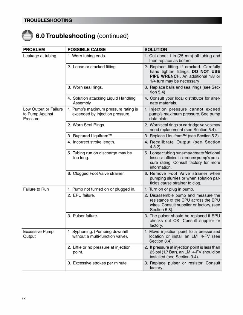
6.0 Troubleshooting (continued)
PROBLEM POSSIBLE CAUSE SOLUTION
Leakage at tubing 1. Worn tubing ends. 1. Cut about 1 in (25 mm) off tubing and then replace as before.
2. Loose or cracked fitting. 2. Replace fitting if cracked. Carefully hand tighten fittings. DO NOT USE
PIPE WRENCH. An additional 1/8 or 1/4 turn may be necessary
3. Worn seal rings. 3. Replace balls and seal rings (see Sec-tion 5.4)
4. Solution attacking Liquid Handling Assembly
4. Consult your local distributor for alter-nate materials.
Low Output or Failure to Pump Against Pressure
1. Pump’s maximum pressure rating is exceeded by injection pressure.
1. Injection pressure cannot exceed pump’s maximum pressure. See pump data plate.
2. Worn Seal Rings. 2. Worn seal rings or cartridge valves may need replacement (see Section 5.4).
3. Ruptured Liquifram™. 3. Replace Liquifram™ (see Section 5.3).
4. Incorrect stroke length. 4. Recalibrate Output (see Section 4.3.2)
5. Tubing run on discharge may be too long.
5. Longer tubing runs may create frictional losses sufficient to reduce pump’s pres-sure rating. Consult factory for more information.
6. Clogged Foot Valve strainer. 6. Remove Foot Valve strainer when pumping slurries or when solution par-ticles cause strainer to clog.
Failure to Run 1. Pump not turned on or plugged in. 1. Turn on or plug in pump.
2. EPU failure. 2. Disassemble pump and measure the resistance of the EPU across the EPU wires. Consult supplier or factory. (see Section 5.8).
3. Pulser failure. 3. The pulser should be replaced if EPU checks out OK. Consult supplier or factory.
Excessive Pump Output
1. Syphoning. (Pumping downhill without a multi-function valve).
1. Move injection point to a pressurized location or install an LMI 4-FV (see Section 3.4).
2. Little or no pressure at injection point.
2. If pressure at injection point is less than 25 psi (1.7 Bar), an LMI 4-FV should be installed (see Section 3.4).
3. Excessive strokes per minute. 3. Replace pulser or resistor. Consult factory.
39
NOTES
Liquifram, Liquitron, Micropace, FastPrime, AutoPrime, and Pro Pac are trademarks of Milton Roy Company, Teflon is a registered trademark of E. I. du Pont de Nemours & Co., Inc.


![INSTRUCTION MANUALmanuals.hobbico.com/hmx/hmxe0210-manual.pdfINSTRUCTION MANUAL Rotor Diameter:27.5 in [700mm] Weight: 19–22 oz [580–760g] Length: 25.4 in [645mm] Height: 9 in](https://static.documents.pub/doc/80x56/607a12483c513f15815da72a/instruction-instruction-manual-rotor-diameter275-in-700mm-weight-19a22-oz.jpg)


![NORTA MIT PRESENTATION.pptx [Read-Only] · • Centrifugal pumps • Side channel pumps • Gear pumps • Screw pumps • Single screw pumps • Piston pumps • Vacuum pumps •](https://static.documents.pub/doc/80x56/5ec27ab9e3ef591d10504c3a/norta-mit-read-only-a-centrifugal-pumps-a-side-channel-pumps-a-gear-pumps.jpg)


