26
I N S T R U C T I O N M A N U A L

I N S T R U C T I O N M A N U A L

Table of Contents
Introduction
Theory of Operation ................................................................................................................................
Specifications ...........................................................................................................................................
KP1H Components .............................................................................................................................................
Installation and Assembly
Single Proportioner Installation ...........................................................................................................
KP1H Complete Installation ...................................................................................................................
Multiple Proportioner Installation .......................................................................................................
KP1H Mixing Center Installation ........................................................................................................
Changing Product Configurations .......................................................................................................
Dilution Ratio Chart .........................................................................................................................................
Calibrating Product Ratios ............................................................................................................................
Dial 4 Selector Positioning ..................................................................................................................
Changing Flow Rates .............................................................................................................................
Pressure Regulation ................................................................................................................................
Troubleshooting .......................................................................................................................................
Maintenance ..............................................................................................................................................
Warranty ..............................................................................................................................................
DISCLAIMERKnight LLC does not accept responsibility for the mishandling, misuse, or non-performance of the described items whenused for purposes other than those specified in the instructions. For hazardous materials information consult label,MSDS, or Knight LLC. Knight products are not for use in potentially explosive environments. Any use of our equipmentin such an environment is at the risk of the user, Knight does not accept any liability in such circumstances.
©2004 by KNIGHT, LLC. • A Unit of IDEX. KP1H, Aire Gap, Flex Gap are trademarks of KNIGHT. All other brands and product names are trademarks or registeredtrademarks of their respective owners.
1
1
2
4
6
8
9
12
14
14
14
15
16
16
17
17

The Knight KP1H is a chemical proportioning system uniquely engineered to be both versatile and scalable. TheKP1H system is built as a single product bottle or bucket fill dispenser, or multiple product Dial 4 dispenser. Itsmodular design allows the installer to convert from one product configuration to another (6 differentconfiguration capability) with only a few changes of snap-on parts. Each KP1H proportioning unit can be linkedtogether to form a daisy chain with an unlimited number of configurations. The KP1H system easily adapts tothe changing needs of any institutional or industrial cleaning application.
The KP1H provides two means for dispenser activation. The revolutionary “One-Hand” filling of spray bottlesfeatures an easy to use bottle actuator that makes bottle fill easier than ever. For customers who prefer “LockingButton” operation to fill buckets or bottles, the “Easy Lock” button can be added.
Flex Gap™ and Aire Gap™ backflow devices with different flow rates are installed to meet plumbingcode requirements for most city, state, county or worldwide regulations.
KP1H MIXING CENTERThe KP1H Center is an integrated “turn-key” dispensing solution with the KP1H Proportioners mounted on adurable stainless steel locking enclosure with a removable drip tray. The center is built as a single container ordouble container unit. Each center holds two KP1H proportioners that can dispense from up to five differentproducts.
THEORY OF OPERATIONThe KP1H will activate and dispense the chemicals at the proper dilution rate when the button or actuator ispressed and will stop when the actuator is released.
• Button activated units: The “easy touch” button operates like a switch. A straight push instantly activatesthe valve for intermittent feed. Pushing the button in and upward “locks” the button in place forbucket fill.
• Bottle activated units: Allows the operator to insert the spray bottle over the pre-formed Fill Tube andpush in the actuator arm to start the dispensing process, much like a self-serve beverage machine.
• KP1H Dial 4 units: Allows from 1 to 4 chemicals to be dispensed, each with its own dilution rate. Theoperator turns the dial selector knob to the chemical to be dispensed and activates the unit using thebottle or button actuator.
SPECIFICATIONS
Introduction
WATER PRESSUREMax: 125 PSI (8.6 BAR)Min: 25 PSI (1.7 Bar)Opt.: 30 – 60 PSI (2 to 4 Bar)
WATER TEMPERATUREMax: 140º F / 60º C
VACUUM28” (.93 Bar) at 50 PSI (3.4 Bar) (Note: Fluctuating water pressure will cause vacuum to change)
DIMENSIONSKP1H Complete Single 121/4”H x 6 3/4” W x 3 3/4” D
(31 cm H x 17 cm W x 10 cm D)KP1H Complete Dual 121/4”H x 10 3/4” W x 3 3/4” D
(31 cm H x 27 cm W x 10 cm D)KP1H Complete Mixing Station 143/4”H x 13” W x 37 1/2” D
37.47 cm H x 33 cm W x 95.25 cm D)Button Activated KP1H 81/4” H x 61/2" W x 31/4" D
(21 cm H x 16.5 cm W x 8.25 cm D)
Bottle Activated KP1H 121/4”H x 61/2” W x 31/4” D(31 cm H x 16.5 cm W x 8.25 cm D)
4 Product Center 131/2” H x 25” W x 7” D(34 cm H x 64 cm W x 18 cm D)
1 Product Center 131/2” H x 121/2” W x 7” D(34 cm H x 32 cm W x 18 cm D)
MATERIAL OF CONSTRUCTIONAll parts that are in contact withchemicals are made of glass filledpolypropylene, viton, and EPDM.
CHEMICAL COMPATIBILITYContact factory for compatibility of allparts.
1
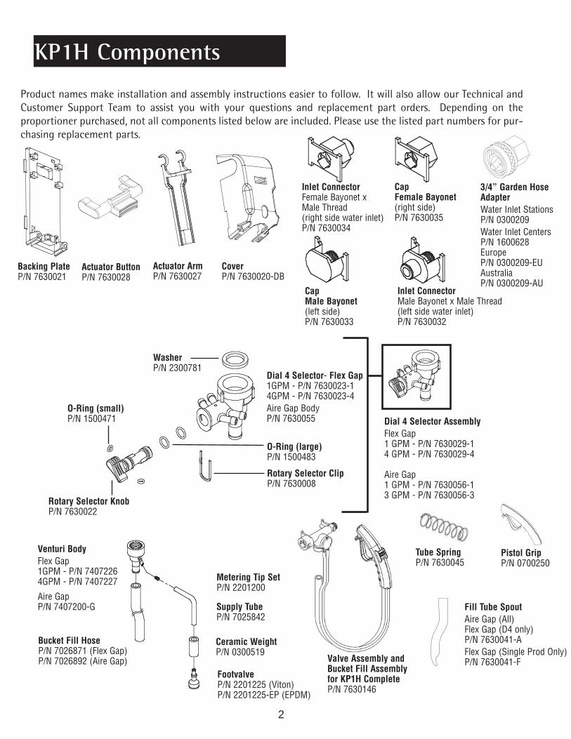
Product names make installation and assembly instructions easier to follow. It will also allow our Technical andCustomer Support Team to assist you with your questions and replacement part orders. Depending on theproportioner purchased, not all components listed below are included. Please use the listed part numbers for pur-chasing replacement parts.
Venturi BodyFlex Gap1GPM - P/N 74072264GPM - P/N 7407227
Aire GapP/N 7407200-G
Metering Tip SetP/N 2201200
Supply TubeP/N 7025842
Ceramic WeightP/N 0300519
FootvalveP/N 2201225 (Viton)P/N 2201225-EP (EPDM)
Bucket Fill HoseP/N 7026871 (Flex Gap)P/N 7026892 (Aire Gap)
WasherP/N 2300781
Dial 4 Selector- Flex Gap1GPM - P/N 7630023-14GPM - P/N 7630023-4Aire Gap BodyP/N 7630055
O-Ring (large)P/N 1500483
Rotary Selector ClipP/N 7630008
Rotary Selector KnobP/N 7630022
O-Ring (small)P/N 1500471
KP1H Components
2
Backing PlateP/N 7630021
Actuator ButtonP/N 7630028
Actuator ArmP/N 7630027
CoverP/N 7630020-DB
Inlet ConnectorFemale Bayonet xMale Thread(right side water inlet)P/N 7630034
CapFemale Bayonet(right side)P/N 7630035
3/4” Garden HoseAdapterWater Inlet StationsP/N 0300209Water Inlet CentersP/N 1600628EuropeP/N 0300209-EUAustraliaP/N 0300209-AU
Inlet ConnectorMale Bayonet x Male Thread(left side water inlet)P/N 7630032
CapMale Bayonet(left side)P/N 7630033
Dial 4 Selector AssemblyFlex Gap1 GPM - P/N 7630029-14 GPM - P/N 7630029-4
Aire Gap1 GPM - P/N 7630056-13 GPM - P/N 7630056-3
Fill Tube SpoutAire Gap (All)Flex Gap (D4 only)P/N 7630041-AFlex Gap (Single Prod Only)P/N 7630041-F
Tube SpringP/N 7630045
Pistol GripP/N 0700250
Valve Assembly andBucket Fill Assemblyfor KP1H CompleteP/N 7630146

3
WasherP/N 2300781
Flex Gap StemP/N 7407208
White SleeveP/N 7001052
Flex Gap Body LongP/N 7407213-G
Valve Bodywithout rear port - P/N 7630026with rear port - P/N 7630025 O-Ring
P/N 1500484
DiaphragmP/N 7121051
SpringP/N 7630037
Tab AssemblyP/N 7630039
Screws (3)P/N 1900894Cap
P/N 7630036
Backflow Venturi
Flex Gap1GPM - P/N 74072194GPM - P/N 7407218
Aire Gap1GPM - P/N 74071543GPM - P/N 7407156
KP1H LABELS
Label designs may be different for custom KP1H systems.
Single Productwithout ButtonP/N 1201388
Single Productwith ButtonP/N 1201388-B
Dial 4without ButtonP/N 1201388-D
Dial 4with ButtonP/N 1201388-DB
Flex Gap Assembly(Long Body Gray)P/N 7407152
Valve Assemblywith Rear PortP/N 7630042orValve Assemblywithout Rear PortP/N 7630043
KP1H ComponentsDial 4 Backflow Venturi
Flex Gap1GPM - P/N 7630019-14GPM - P/N 7630019-4
Aire Gap1GPM - P/N 7407154-D3GPM - P/N 7407156-D
10” Defoam TubeFor 1 GPM OnlyP/N 7025904 KP1H Complete LABELS
P/N 1200289
P/N 1200290
P/N 1200288
P/N 1200287
P/N 12104561
pg19
P/N1200128
LargeChemical LabelsP/N 1200128(see p. 19)
SmallChemical LabelsP/N 1200130 (see p. 18)

Proper installation will help you get the maximum performance and product life from your KP1H system.The following instructions will guide you through the installation of a single bottle fill, bucket fill, orDial 4 Proportioner.
Single Proportioner Installation
1. Remove the cover by loosening two screws near thebottom of the proportioner (screws do not need to becompletely taken off). Then lift the cover up and outusing the open slot at the top of the cover. (Bottle Fillunits have a fill tube spout under the cover, this shouldalso be removed).
To remove cover from a Dial 4 proportioner, the dialknob must be at the 12 o’clock position.
2. Mounting the proportioner is easier with the actuatorarm removed. Remove the actuator arm by lifting upand pulling out on the actuator hook.
3. Mount the unit near a water source and no more than 5 feetfrom the floor. Depending on the wall surface, usetoggle bolts, masonry screws, or wall anchors to mountthe unit on the wall.
4. Connect water source to water inlet fitting adapter.(Refer to page 5 to change water inlet location).
Important note: If proportioner is connected to a janitor’s sink with anatmospheric vacuum breaker, a special connection kit is required by A.S.S.E.specification 1055. Failure to use this kit, or equivalent connection methods willinvalidate the A.S.S.E. and I.A.P.M.O. (UPC) certification. Specify P/N 7600187 whenordering the kit
5. Remove the tie wrap on the backing plate. Attach thefill tube spout to the venturi with the spout openingfacing away from you. Use the tie wrap to secure filltube. (Excess tie wrap may be cut off).
For bucket fill proportioner, attach bucket fill hose to theventuri and secure hose with the tie wrap. (Excess tie wrapmay be cut off).
6. Thread the proper metering tip into the chemical inletport on the side of the venturi body. (See p.14 for tip ratios.)
7. Hook the actuator arm back onto the proportioner. Theactuator arm must be behind the chemical inlet and thefill tube spout.
8. Remove the 3/8” supply tube and tube spring from theaccessory kit. Pull the supply tube through the opening atthe bottom of the backing plate.
Twist the supply tube spring over the tube and attach it tothe inlet barb of the venturi. Spring must be used to preventtube from “kinking”. (For Dial 4 setup, spring is not used.)
Dial 4
4
1 GPM Aire Gap (OPTIONAL)
Attach 10” defoam tube to theventuri and route fill tube spoutover the defoam tube. Cut thedefoam tube as needed. Forbest result, cut defoam tubeenough so that the end stilltouches the bottom of thespray bottle.
Note: Avoidextremely hotwater and veryhigh pressure.
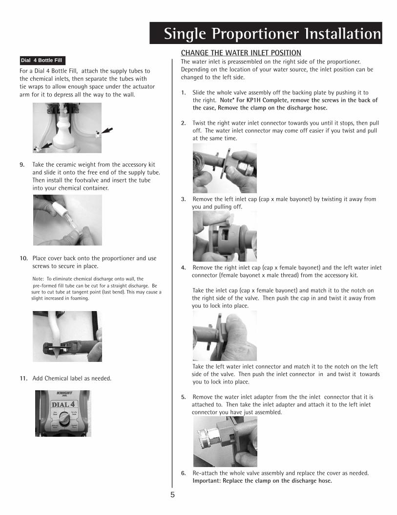
Single Proportioner InstallationCHANGE THE WATER INLET POSITIONThe water inlet is preassembled on the right side of the proportioner.Depending on the location of your water source, the inlet position can bechanged to the left side.
1. Slide the whole valve assembly off the backing plate by pushing it tothe right. Note* For KP1H Complete, remove the screws in the back ofthe case, Remove the clamp on the discharge hose.
2. Twist the right water inlet connector towards you until it stops, then pulloff. The water inlet connector may come off easier if you twist and pullat the same time.
3. Remove the left inlet cap (cap x male bayonet) by twisting it away fromyou and pulling off.
4. Remove the right inlet cap (cap x female bayonet) and the left water inletconnector (female bayonet x male thread) from the accessory kit.
Take the inlet cap (cap x female bayonet) and match it to the notch onthe right side of the valve. Then push the cap in and twist it away fromyou to lock into place.
Take the left water inlet connector and match it to the notch on the leftside of the valve. Then push the inlet connector in and twist it towardsyou to lock into place.
5. Remove the water inlet adapter from the the inlet connector that it isattached to. Then take the inlet adapter and attach it to the left inletconnector you have just assembled.
6. Re-attach the whole valve assembly and replace the cover as needed.Important: Replace the clamp on the discharge hose.
5
For a Dial 4 Bottle Fill, attach the supply tubes tothe chemical inlets, then separate the tubes withtie wraps to allow enough space under the actuatorarm for it to depress all the way to the wall.
9. Take the ceramic weight from the accessory kitand slide it onto the free end of the supply tube.Then install the footvalve and insert the tubeinto your chemical container.
10. Place cover back onto the proportioner and usescrews to secure in place.
Note: To eliminate chemical discharge onto wall, thepre-formed fill tube can be cut for a straight discharge. Be
sure to cut tube at tangent point (last bend). This may cause aslight increased in foaming.
11. Add Chemical label as needed.
Dial 4 Bottle Fill

4. Thread the proper metering tip into the chemical inletport on the side of the venturi body. (See p.14 for tip ratios.)
5. Remove the 3/8” supply tube from theaccessory kit. Push the supply tube through the grommet atthe bottom of the mounting plate. Attach the supply tubesto the inlet barbs of the venturi
For a Dial 4 Bottle Fill, attach the supply tubes to the chemicalinlets, then separate the tubes with tie wraps to allow enoughspace under the actuator arm for it to depress all the way to thewall.
6. Take the ceramic weight from the accessory kitand slide it onto the free end of the supply tube.Then install the footvalve and insert the tubeinto your chemical container.
Dial 4 Bottle Fill
Proper installation will help you get the maximum performance and product life from your KP1H Complete sys-tem. The following instructions will guide you through the installation of a single bottle fill, bucket fill, orDial 4 Proportioner.
KP1H Complete Installation
1. Remove the cover by loosening four screws on the side ofthe proportioner (screws do not need to becompletely taken off). Then lift the cover.
To remove cover from a Dial 4 proportioner, the dialknob must be at the 12 o’clock position.
2. Mount the unit near a water source and no more than 5 feetfrom the floor. Depending on the wall surface, usetoggle bolts, masonry screws, or wall anchors to mountthe unit on the wall.
3. Connect water source to water inlet fitting adapter.(Refer to page 5 to change water inlet location).
Important note: If proportioner is connected to a janitor’s sink with anatmospheric vacuum breaker, a special connection kit is required by A.S.S.E.specification 1055. Failure to use this kit, or equivalent connection methods willinvalidate the A.S.S.E. and I.A.P.M.O. (UPC) certification. Specify P/N 7600187 whenordering the kit
Dial 4
6
Note: Avoidextremely hotwater and veryhigh pressure.

7
7. Place cover back onto the proportioner and usescrews to secure in place.
Note: To eliminate chemical discharge onto wall, thepre-formed fill tube can be cut for a straight discharge. Be
sure to cut tube at tangent point (last bend). This may cause aslight increased in foaming.
8. Add Chemical label as needed.
Note: Turn OFF water using Ball-Valve onWater Inlet when NOT in use.

Bottle Fill, Bucket Fill, and Dial 4 proportioners can be linked together in any combination. There is no limit tothe possibilities. To assemble multiple proportioners, follow the instruction below and always start from the leftand add onto the right. Note: Use a lubricant (KTL-20 or equivalent) on the “O”-ring to make assembly easier.
Multiple Proportioner Installation
1. Remove the cover of the first proportioner by loosening twoscrews at the bottom (screws do not need to be completelytaken off). Then lift the cover up and out using the open slotat the top of the cover. (Bottle Fill units have a fill tube spoutunder the cover, this should also be removed).
To remove cover from a Dial 4 proportioner, the dialknob must be at the 12 o’clock position.
2. Slide the whole valve assembly off the backing plate bypushing it to the right.
3. Twist the right water inlet connector towards you until itstops then pull off. The water inlet connector may comeoff easier if you twist and pull at the same time.
4. Remove the left inlet cap (cap x male bayonet) from the nextproportioner by twisting it away from you and pulling off.
5. Connect the male bayonet from the first proportionerto the female bayonet of the second proportioner. Whenthe notch of the two valves are lined up properly, simplypush together and twist into place.
Continue with steps 1 through 5 until all valveassemblies are connected.
6. Slide the backing plates on one at a time (starting fromthe left) until all the backing plates are in place. Thenfollow steps 2 through 11 on pages 4 and 5 to finish theinstallation.
Dial 4
8

9
In the accessory kits, you will find some extra 8-32 nuts. These nuts will be used as “spacers” when mountingtwo KP1H Centers side-by-side. This will increase the spacing between the units and allow the doors to closemore easily. The screws will also act as guides when lining up the units side-by side.
KP1H Mixing Center Installation
Mounting the Cases
1. Find a total of four 8-32 screws from the KP1H Centeraccessory kits. (Each kit contains two screws and four nuts)
• Insert the screws through the mounting embosses fromthe inside of the case, as shown to the right.
3. Align the screws with the corresponding holes in themounting embosses of the second KP1H Center,as shown to the right.
4. Find the four 8-32 nuts with star washers from theKP1H Center accessory kits.
• Slide the two cabinets together, and thread onthe nuts with the washers facing the case. Tightenthe nuts securely and your done.
2. Thread on the four 8-32 nuts from the accessory kits, asshown to the right.
• Tighten the nuts about 1/4 turn past hand-tight.
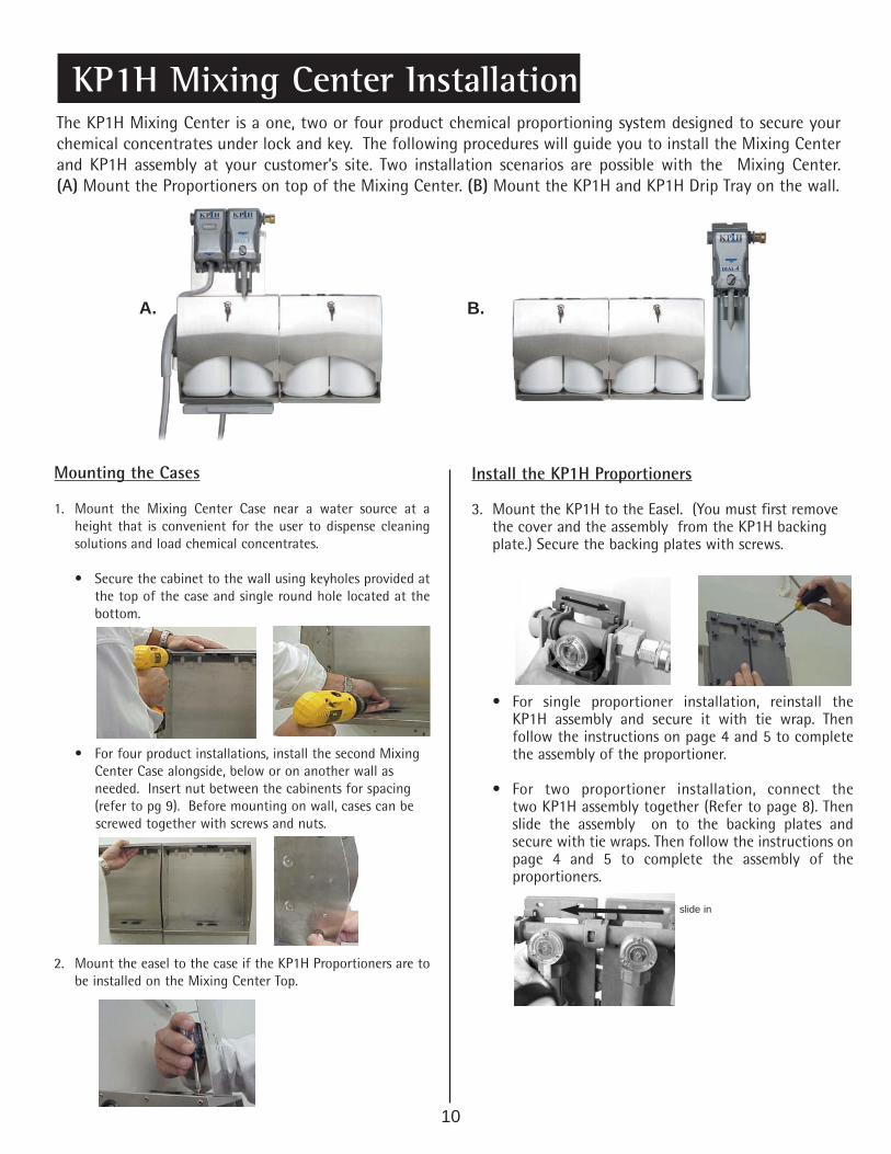
The KP1H Mixing Center is a one, two or four product chemical proportioning system designed to secure yourchemical concentrates under lock and key. The following procedures will guide you to install the Mixing Centerand KP1H assembly at your customer’s site. Two installation scenarios are possible with the Mixing Center.(A) Mount the Proportioners on top of the Mixing Center. (B) Mount the KP1H and KP1H Drip Tray on the wall.
Mounting the Cases
1. Mount the Mixing Center Case near a water source at aheight that is convenient for the user to dispense cleaningsolutions and load chemical concentrates.
• Secure the cabinet to the wall using keyholes provided atthe top of the case and single round hole located at thebottom.
• For four product installations, install the second MixingCenter Case alongside, below or on another wall asneeded. Insert nut between the cabinents for spacing(refer to pg 9). Before mounting on wall, cases can bescrewed together with screws and nuts.
2. Mount the easel to the case if the KP1H Proportioners are tobe installed on the Mixing Center Top.
KP1H Mixing Center Installation
Install the KP1H Proportioners
3. Mount the KP1H to the Easel. (You must first removethe cover and the assembly from the KP1H backingplate.) Secure the backing plates with screws.
• For single proportioner installation, reinstall theKP1H assembly and secure it with tie wrap. Thenfollow the instructions on page 4 and 5 to completethe assembly of the proportioner.
• For two proportioner installation, connect thetwo KP1H assembly together (Refer to page 8). Thenslide the assembly on to the backing plates andsecure with tie wraps. Then follow the instructions onpage 4 and 5 to complete the assembly of theproportioners.
A. B.
slide in
10

KP1H Mixing Center Installation
7. Route and connect the chemical inlet lines for the Dial 4 andbucket Fill through the holes in the top of the Mixing CenterCase.
8. Mount Drip Tray to case bottom using screws and nutsprovided.
9. Attach 3/8” drain tube to the nipple on the Drip Tray androute the tube to a suitable drain or slop sink. Place yourchemical container(s) in the Mixing Center Case.
10. Pressurize the system and test the system for leaks.
4. Install the bucket fill hose grip bracket on the side ofthe case.
Connecting The Bucket Fill Hose
5. Connect 3/4” O.D vinyl bucket fill hose with flowrestrictor over high flow venturi. The end closestto the plastic flow restrictor insert (single productFlex-Gap only) must be connected to the valve.Secure hose with tie wrap.
• Route the bucket fill hose above the mixing center doorand along side panel as shown. Install plastic bucket fillhose retainer on side of mixing center case.
6. The KP1H Mixing Center is shipped with a plastic3/4” MGHT x 3/8” barb elbow fitting. Use this fittingalong with a standard 1/2” O.D. appliance hose tosupply water to the KP1H Proportioner.
• Route the female end of the hose through the large holein the top and bottom of the Mixing Center Case. Cut themale end of the hose off and push bare hose end overbarb fittings as shown. Secure the hose with a stainlesssteel hose clamp to prevent leaks.
11

The KP1H Complete Mixing Station is a one, two or four product chemical proportioning system designed tosecure your chemical concentrates under lock and key. The following procedures will guide you to install theMixing Station assembly at your customer’s site.
c. Cabinet held by the joggle bracket shown below.
d. Open the cabinet doors and drill the anchor screws intothe wall through the holes located at the lower back ofthe cabinet..
12
KP1H Complete Mixing Station Installation
Mounting the Cabinet
1. Mount the Mixing Center assembly near a water source at aheight that is convenient for the user to dispense cleaningsolutions and load chemical concentrates.
a. Attach the supplied joggle bracket onto the wall using thesupplied wall mounting kit.
b. Secure the cabinet to the wall by sliding down the malejoggle bracket at the top of the case down onto thefemale joggle bracket on the wall.
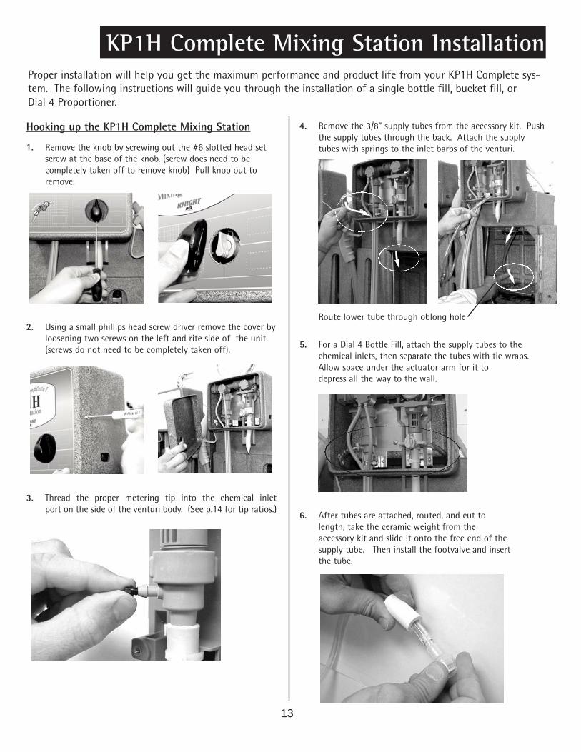
Proper installation will help you get the maximum performance and product life from your KP1H Complete sys-tem. The following instructions will guide you through the installation of a single bottle fill, bucket fill, orDial 4 Proportioner.
13
KP1H Complete Mixing Station Installation
4. Remove the 3/8” supply tubes from the accessory kit. Pushthe supply tubes through the back. Attach the supplytubes with springs to the inlet barbs of the venturi.
Route lower tube through oblong hole
5. For a Dial 4 Bottle Fill, attach the supply tubes to thechemical inlets, then separate the tubes with tie wraps.Allow space under the actuator arm for it todepress all the way to the wall.
6. After tubes are attached, routed, and cut tolength, take the ceramic weight from theaccessory kit and slide it onto the free end of thesupply tube. Then install the footvalve and insertthe tube.
Hooking up the KP1H Complete Mixing Station
1. Remove the knob by screwing out the #6 slotted head setscrew at the base of the knob. (screw does need to becompletely taken off to remove knob) Pull knob out toremove.
2. Using a small phillips head screw driver remove the cover byloosening two screws on the left and rite side of the unit.(screws do not need to be completely taken off).
3. Thread the proper metering tip into the chemical inletport on the side of the venturi body. (See p.14 for tip ratios.)

KP1H Complete Mixing Station Installation
14
7. Place cover back onto the proportioner and usescrews to secure in place.
Note: To eliminate chemical discharge onto wall, thepre-formed fill tube can be cut for a straight discharge. Besure to cut tube at tangent point (last bend). This may cause aslight increased in foaming.
8. Add Chemical label as needed.
9. Connect water source to water inlet fitting adapter.(Refer to page 5 to change water inlet location).
10. Installing drain port
11. Reattach covera. Screw in the side screws.
b. Attach knob with the set screw.
Note: Avoid extremelyhot water and very highpressure.
Important note: If proportioner is connected to a janitor’s sink with anatmospheric vacuum breaker, a special connection kit is required by A.S.S.E.specification 1055. Failure to use this kit, or equivalent connection methods willinvalidate the A.S.S.E. and I.A.P.M.O. (UPC) certification. Specify P/N 7600187when ordering the kit

KP1H Complete Mixing Station Installation
15
Door Locking Procedure
1. Turn key lock up.
2. Close left door first, then close right door next over the leftdoor.
3. Push doors in and turn the key lock down.
Holstering the bucket fill gun

The KP1H system can be a bottle fill, bucket fill or Dial 4. To change from one product configuration toanother, simply swap a few parts to create a whole new system.
Changing Product Configurations
CHANGE BUTTON ACTIVATION TO BOTTLE ACTIVATION
CHANGE BOTTLE FILL TO BUCKET FILL
1. Remove the cover and pull out the actuatorbutton.
2. Hook the actuator arm on the valve assembly.3. Remove the label from the cover and replace it
with the label with no button hole.4. Place the cover back and secure with screws.
1. Remove the cover and pull off the actuator arm.2. Cut the plastic tie wrap around the fill tube
spout, then remove the tube.3. Remove the Lt. Gray (1GM) Flex Gap venturi
body by turning it counter clockwise.4. Replace the Lt Gray Flex Gap venturi body with a Dk. Gray
(4 GPM) Flex Gap venturi body. Turn the venturi bodyclockwise to secure in place.
5. Slide on the bucket fill hose (with “flow” restrictor for SingleProduct Flex Gap towards the valve). Use tie wrap to secure inplace.
6. Remove the label from the cover and slip the buttonactuator into the corresponding slot on the cover.
7. Place the cover back on the unit and secure itwith screws.
8. Add the new label with button hole to the cover.
Add ChemicalLabels as Needed
Add ChemicalLabels as Needed
16
Changing Product Configurations
17
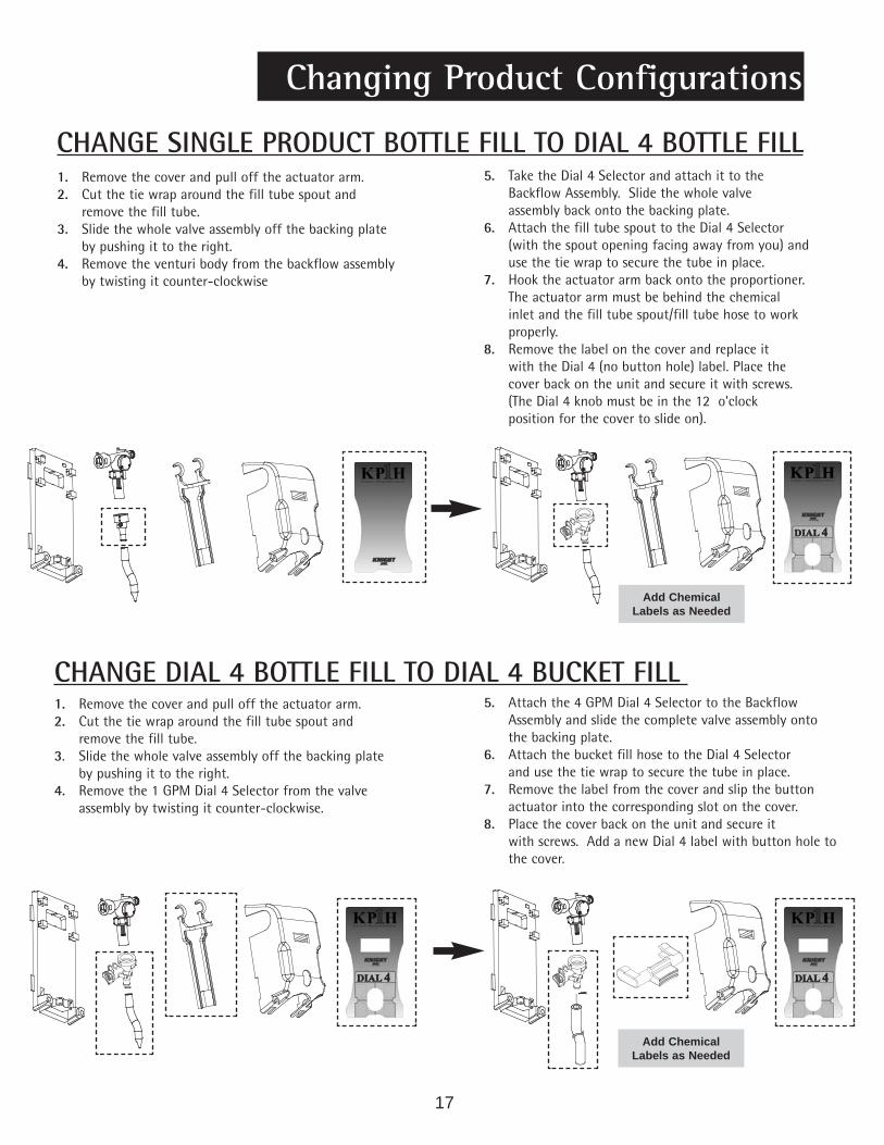
CHANGE SINGLE PRODUCT BOTTLE FILL TO DIAL 4 BOTTLE FILL
CHANGE DIAL 4 BOTTLE FILL TO DIAL 4 BUCKET FILL
1. Remove the cover and pull off the actuator arm.2. Cut the tie wrap around the fill tube spout and
remove the fill tube.3. Slide the whole valve assembly off the backing plate
by pushing it to the right.4. Remove the venturi body from the backflow assembly
by twisting it counter-clockwise
5. Take the Dial 4 Selector and attach it to theBackflow Assembly. Slide the whole valveassembly back onto the backing plate.
6. Attach the fill tube spout to the Dial 4 Selector(with the spout opening facing away from you) anduse the tie wrap to secure the tube in place.
7. Hook the actuator arm back onto the proportioner.The actuator arm must be behind the chemicalinlet and the fill tube spout/fill tube hose to workproperly.
8. Remove the label on the cover and replace itwith the Dial 4 (no button hole) label. Place thecover back on the unit and secure it with screws.(The Dial 4 knob must be in the 12 o’clockposition for the cover to slide on).
1. Remove the cover and pull off the actuator arm.2. Cut the tie wrap around the fill tube spout and
remove the fill tube.3. Slide the whole valve assembly off the backing plate
by pushing it to the right.4. Remove the 1 GPM Dial 4 Selector from the valve
assembly by twisting it counter-clockwise.
5. Attach the 4 GPM Dial 4 Selector to the BackflowAssembly and slide the complete valve assembly ontothe backing plate.
6. Attach the bucket fill hose to the Dial 4 Selectorand use the tie wrap to secure the tube in place.
7. Remove the label from the cover and slip the buttonactuator into the corresponding slot on the cover.
8. Place the cover back on the unit and secure itwith screws. Add a new Dial 4 label with button hole tothe cover.
Add ChemicalLabels as Needed
Add ChemicalLabels as Needed
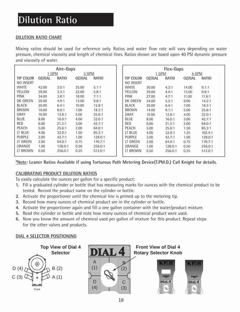
DILUTION RATIO CHART
Mixing ratios should be used for reference only. Ratios and water flow rate will vary depending on waterpressure, chemical viscosity and length of chemical lines. Ratios shown are based upon 40 PSI dynamic pressureand viscosity of water.
*Note: Leaner Ratios Available if using Torturous Path Metering Device(T.PM.D.) Call Knight for details.
CALIBRATING PRODUCT DILUTION RATIOSTo easily calculate the ounces per gallon for a specific product:1. Fill a graduated cylinder or bottle that has measuring marks for ounces with the chemical product to be
tested. Record the product name on the cylinder or bottle.2. Activate the proportioner until the chemical line is primed up to the metering tip.3. Record how many ounces of chemical product are in the cylinder or bottle.4. Activate the proportioner again and fill a one gallon container with the water/product mixture.5. Read the cylinder or bottle and note how many ounces of chemical product were used.6. Now you know the amount of chemical used per gallon of mixture for this product. Repeat steps
for the other valves and products.
DIAL 4 SELECTOR POSITIONING
Dilution Ratio
4
3
2
1
Aire-Gaps1 GPM 3 GPM
TIP COLOR OZ/GAL RATIO OZ/GAL RATIONO INSERTWHITE 42.00 3.0:1 25.00 5.1:1YELLOW 39.00 3.3:1 22.00 5.8:1PINK 34.00 3.8:1 18.00 7.1:1DK GREEN 26.00 4.9:1 13.00 9.8:1BLACK 20.00 6.4:1 10.00 12.8:1BROWN 16.00 8.0:1 7.00 18.3:1GRAY 10.00 12.8:1 5.00 25.6:1BLUE 8.00 16.0:1 4.00 32.0:1RED 6.00 21.3:1 3.00 42.7:1PEACH 5.00 25.6:1 2.00 64.0:1LT BLUE 4.00 32.0:1 1.50 85.3:1PURPLE 3.00 42.7:1 1.00 128.0:1LT GREEN 2.00 64.0:1 0.75 170.7:1ORANGE 1.00 128.0:1 0.50 256.0:1LT BROWN 0.50 256.0:1 0.25 512.0:1
Flex-Gaps1 GPM 4 GPM
TIP COLOR OZ/GAL RATIO OZ/GAL RATIONO INSERTWHITE 30.00 4.3:1 14.00 9.1:1YELLOW 29.00 4.4:1 13.00 9.8:1PINK 27.00 4.7:1 11.00 11.6:1DK GREEN 24.00 5.3:1 9.00 14.2:1BLACK 20.00 6.4:1 7.00 18.3:1BROWN 14.00 9.1:1 5.00 25.6:1GRAY 10.00 12.8:1 4.00 32.0:1BLUE 8.00 16.0:1 3.00 42.7:1RED 6.00 21.3:1 2.00 64.0:1PEACH 5.00 25.6:1 1.50 85.3:1LT BLUE 4.00 32.0:1 1.25 102.4:1PURPLE 3.00 42.7:1 1.00 128.0:1LT GREEN 2.00 64.0:1 0.75 170.7:1ORANGE 1.00 128.0:1 0.50 256.0:1LT BROWN 0.50 256.0:1 0.25 512.0:1
18
Front
Top View of Dial 4Selector
Front View of Dial 4Rotary Selector Knob
4
B (2)
C (3)
D (4)
A (1)
B(2)
C(3)
D(4)
A(1)
B(2)
C(3)
D(4)
A(1)
B(2)
C(3)
D(4)
A(1)

Changing Flow Rates
Screen WasherP/N 2300812
Nozzle ScreenP/N 7407211
Nozzle1GPM P/N 74072013GPM P/N 7407202
Aire Gap BodyP/N 7407200-G
Deflector Plate1GPM P/N 74072203 GPM P/N 7407221
Rubber Washer P/N 2300823
Aire Gap Venturi Tube1GPM 74072043GPM 7407205
O-RingP/N 1500477
Aire Gap Venturi BodyP/N 7407225 (single product)*P/N 7630055 (Dial 4)*Note: Body only, does not include selectorknob or other parts - see p. 2
De-Foam TubeP/N 7025904For 1 GPM Only
AIRE GAP ASSEMBLY
19
FLEX GAPS
The Flex Gap venturi body is molded for either a 1 or 4GPM flow rate. To change the flow rate:
LIGHT GRAY = 1GPMDARK GRAY = 4GPM
1. Remove the Flex Gap venturi body by turning itcounter clockwise.
2. Install the appropriate venturi body.
(Note: For Dial 4 s remove the valve assembly from thebacking plate first, then remove the Dial 4 selector byturning it counter clockwise. Replace with desired GPMmodel.)
AIRE-GAPS
For Aire-Gap venturi systems, the flow rate is controlledby a nozzle, deflector plate, and venturi tube. Theseinternal parts are color coded to identify their GPMrating:
Blue = 1 GPMBlack = 3 GPM
To change these parts:
1. Disconnect tubing from venturi body.
2. Remove Aire Gap assembly from water valve.
3. Remove existing nozzle, deflector plate, and venturitube by disassembling the Aire Gap. (See figure)
4. Reassemble the Aire Gap using new nozzle,deflector plate, and venturi tube (for the desired flowrate). To avoid leakage, install the rubber washerwith the 3 “ears” facing upwards. Hand-tighten theventuri body to the Aire Gap body.
5. Thread Aire Gap assembly back and hand-tighten inplace.

The optimum water pressure to create maximum vacuum is 30 – 60 PSI. Use of the Brass Pressure Regulator (P/N7407117 ) on the input side of the KP1H Complete is Mandatory for safe operation of this System. The regulatorwill prevent the flow pressure from exceeding 45 PSI.
Knight recommends a fixed pressure regulator that threads into a standard garden hose adapter,
Knight #7407117(as shown)
TROUBLESHOOTING
1. Dispenser will not draw chemical:A. Check metering tip for obstruction.B. Check water pressure for 30 – 60 PSI.C. Check or change footvalve.
2. Dispenser leaks at joints:A. Ensure that both “O”- rings are in place on bayonet end of valve body.B. Inspect “O”-rings for damage and for lubrication.
3. Mixed chemical concentration is too weak:A. Check water pressure for a minimum of 25 PSI of flow pressure.B. Change metering tip to a higher dilution ratio.
4. Valve activates when cover is pressed:A. Make sure backing plate has mounting screw in top and bottom corners.
5. Supply line loses chemical prime:A. Check or change foot valve.
6. Water leaks at cap on valve assembly:A. Loose or “stripped” screw. Replace screw.B. Excessive water pressure. Use Regulator.
7. Button or bottle actuator will not activate valve:A. The cover is loose or damaged, tighten screws or replace the cover,B. Adjust calibration screw until full flow is achieved.
8. Dial 4 will not draw chemical:A. Check condition of o-rings on dial selector knobB. Ensure Dial “Clicks” to selected product.
9. Low water flow:A. Check that cover is firmly attached.B. Check for sediment in screen washer or valve body.C. Check water pressure.
Pressure Regulation
1. Disconnect water lineand attach pressureregulator to water inletadapter.
2. Reconnect waterline to adapter onregulator.
20
Proper product maintenance can improvethe performance and extend the productlife of your KP1H system. Periodicallycheck the following:• Metering tips for proper dilution rate.• Screen on foot valve to make sure
supply line is staying primed.• Button activation for proper opera
tion. If activation is not correct, checkcover; if the cover is loose,tighten the screws on the cover.
Knight controls and pump systems are war-ranted against defects in material and work-manship for a period of ONE YEAR. AllElectronic Control Boards have a TWO YEARwarranty. Warranty applies only to the re-placement or repair of such parts when re-turned to the factory with a KRA number,freight prepaid and found to be defective up-on factory inspection. Rubber and syntheticrubber parts such as "O" rings, diaphragms,squeeze tubing and gaskets are considered ex-pendable and are not covered under warran-ty. Warranty does not cover liability resultingfrom performance of this equipment nor thelabor to replace this equipment. Productabuse or misuse voids warranty.
The information and specifications included inthis publication were in effect at the time ofapproval for printing. Knight, LLC reserves theright, however, to discontinue or changespecifications or design at any time withoutnotice and without incurring any obligationwhatsoever.
Maintenance
Warranty
21
Footnote

22
FLEX-GAP ANNUAL CLEANING AND TEST PROCEDURES FOR UNITS INSTALLED IN CANADA
Each year, your chemical dispenser must be cleaned and its backflow prevention performance verified. As thisdevice is an end-of-line device (versus an in-line device) and evidence of effective backflow prevention isdetermined visually, a two-minute pressure test is not necessary.
If the Flex-Gap device cannot readily be seen during the test procedure, the housing of the chemical dis-pensing unit must be removed during testing. Apply the appropriate test procedure below as applicable foryour chemical dispensing unit.
4 GPM VENTURIS
1. Fill discharge hose with water by opening the valve.2. When water begins to exit the discharge hose turn off the water and raise the end of the hose above
the Flex-Gap.3. Observe that water is exiting the Flex-Gap.4. If the water is exiting the Flex-Gap it has passed the test.5. If the water is not exiting from the Flex-Gap, replace the Flex-Gap sleeve as per the instruction
manual and re-test.6. If the water is not exiting from the Flex-Gap after replacing the sleeve and re-testing, replace the
complete Flex-Gap assembly and re-test.7. If the water is not exiting from the Flex-Gap after replacing the Flex-Gap assembly, disconnect the
water supply and replace the complete unit.
1 GPM VENTURIS
1. Remove the Fill Tube Spout and replace with a 4-foot length of 1/2” ID hose.2. Fill the discharge hose with water by opening the valve.3. When water begins to exit the discharge hose, turn off the water and raise the end of the hose above
the Flex-Gap.4. Observe that water is exiting the Flex-Gap.5. If the water is exiting the Flex-Gap, it has passed the test.6. If the water is not exiting from the Flex-Gap, replace the Flex-Gap sleeve and re-test.7. If the water is not exiting from the Flex-Gap after replacing the sleeve and re-testing, replace the
complete Flex-Gap assembly and re-test.8. If the water is not exiting from the Flex-Gap after replacing the Flex-Gap assembly, disconnect the
water supply and replace the complete unit.
Flex-Gap Cleaning and Test Procedures
23

KP1H Instruction Manual Part Number 0900875 Rev: L (10/2007)
Knight Headquarters Knight Canada Knight Europe Knight Australia Knight N. Asia Knight S. AsiaToll Free (800)854-3764 Tel (905)542-2333 Tel +44(1293)615.570 Tel +61(2)9725.2588 Tel +82(2)3481.6683 Tel +65.9170.0984Tel (949) 595-4800 Fax (905)542-1536 Fax +44(1293)615.585 Fax +61(2)9725.2025 Fax +82(2)3482.5742 Fax +65.6489.6723Fax (949)595-4801www.knightequip.com


