21
MANUALLY PROGRAMMING THE SNAP-ON LEVEL 5 GEN 3 LOCK Instruction Manual

MANUALLY PROGRAMMING THE SNAP-ON LEVEL 5 GEN 3 LOCK Instruction Manual
Level 5 NTC

Setting up the Snap-on Level 5 Gen3 Lock Manual
Setting up the Snap-on Level 5 Gen3 Lock ..................................................................................................................... 3Basic Setup ........................................................................................................................................................................ 4Main Slave / Aux Slave Setup ............................................................................................................................................. 5Ethernet Setup ................................................................................................................................................................... 6Wi-Fi Setup ........................................................................................................................................................................ 7Getting Started ................................................................................................................................................................... 8
Manual Programming at the Access Panel ...................................................................................................................... 11Creating Users .................................................................................................................................................................... 11Erasing Users ..................................................................................................................................................................... 11Viewing Users ..................................................................................................................................................................... 11Editing Users ...................................................................................................................................................................... 12
Access Panel Permissions by Supervisor Level ................................................................................................................ 14Manual Programming – Lock Settings ............................................................................................................................ 15
Setting the Clock ................................................................................................................................................................ 15Changing Tilt Sensitivity ...................................................................................................................................................... 15Changing Beep Volume ....................................................................................................................................................... 15Review Messages ............................................................................................................................................................... 16
Using the Snap-on Level 5 Gen3 Lock ............................................................................................................................ 17Opening/Closing the Toolbox lock ....................................................................................................................................... 17Activating Tilt Alarm ............................................................................................................................................................ 17Test Wi-Fi Network .............................................................................................................................................................. 17User Log ............................................................................................................................................................................. 17Access Log ......................................................................................................................................................................... 18Visual Inventory Status ....................................................................................................................................................... 18
Access Panel Display ..................................................................................................................................................... 19Date/time .......................................................................................................................................................................... 19Remaining battery charge ................................................................................................................................................... 19Card reader type (prox, magstripe, barcode, no reader) ....................................................................................................... 20Lock serial number ............................................................................................................................................................. 20Control module firmware version ......................................................................................................................................... 20Access panel firmware version ............................................................................................................................................ 20
TABLE OF CONTENTS
Level 5 NTC Operator’s Manual – Manual Programming of the Snap-on Level 5 Gen3 Lock

Level 5 NTC Operator’s Manual – Manual Programming of the Snap-on Level 5 Gen3 Lock
3
TABLE OF CONTENTS continued
Other manuals available as separate pdfs:
w Database & Network Configuration & Install Manual
w LockView NTC Instruction Manual
LockView NTC Instruction
Manual
NO
NO
YES
go to
go toYES
Setting up the Snap-on Level 5 Gen 3 Lock
Manual
Is LockViewNTC Software going to be
used?
Setting up the Snap-on Level 5 Gen 3 Lock
Manual
Database & Network
Configuration & Installation
Manual
Will the locks be 802.11 or Ethernet networked?
The following chart is intended to serve as a guide to provide for the most logical and efficient set-up of the Snap-on Level 5 Tool Control System.

Level 5 NTC Operator’s Manual – Manual Programming of the Snap-on Level 5 Gen3 Lock
4
Basic / Standalone Setup
SETTING UP THE SNAP-ON LEVEL 5 GEN3 LOCK
L5BPG3Battery Module
L5PROXG3Access Panel
(Keypad/Prox shown)
L5LMG3Lock Module
L5WHBTG3Battery Cable
L5WHACG3Access Panel
Cable
Note: part numbers on this page are Snap-on part numbers.

Level 5 NTC Operator’s Manual – Manual Programming of the Snap-on Level 5 Gen3 Lock
5
Main Slave / Aux Slave Setup
SETTING UP THE SNAP-ON LEVEL 5 GEN3 LOCK continued
L5BPG3Battery Module
L5PROXG3Access Panel
(Keypad/Prox shown)
L5WHBTG3Battery Cable
Note: part numbers on this page are Snap-on part numbers.
L5WHACG3Access Panel
Cable
Main SlaveL5SUG3
Includes CableL5WHSUG3
L5WHSUG3Slave cable
L5WHSUG3Slave cable
CompX eLatchor 12V strike(not included)
L5LMG3Lock Module
Auxiliary Slave ModuleL5SUAUXG3
Includes cableL5WHSUG3
L5WHSUG3Slave cable

Level 5 NTC Operator’s Manual – Manual Programming of the Snap-on Level 5 Gen3 Lock
6
SETTING UP THE SNAP-ON LEVEL 5 GEN3 LOCK continued
Ethernet Setup
L5BPG3Battery Module
L5PROXG3Access Panel
(Keypad/Prox shown)
L5WHBTG3Battery Cable
L5WHACG3Access Panel
Cable
ToEthernet Port(not included)
L5LMG3Lock Module
L5ETHERG3Ethernet Module
Includes Interconnect Cable
Note: part numbers on this page are Snap-on part numbers.

Level 5 NTC Operator’s Manual – Manual Programming of the Snap-on Level 5 Gen3 Lock
7
SETTING UP THE SNAP-ON LEVEL 5 GEN3 LOCK continued
Wi-Fi Setup
L5BPG3Battery Module
L5PROXG3Access Panel
(Keypad/Prox shown)
L5WHBTG3Battery Cable
L5WHACG3Access Panel
Cable
To WirelessNetwork
(not included)
L5LMG3Lock Module
L580211GWi-Fi Module
(includes interconnect cable)
Note: part numbers on this page are Snap-on part numbers.

Level 5 NTC Operator’s Manual – Manual Programming of the Snap-on Level 5 Gen3 Lock
8
Getting StartedManual mode (NOT using LockView)Each lock is shipped pre-programmed with a default PIN (Personal Identification Number) 2 8 0 1.In order to ensure the security of the tool box, 2 8 0 1 should be removed AND replaced by following the below steps.
1) Press “Menu/Select” button. “LOGIN PLEASE” is displayed.
2) Key in 2 8 0 1 followed by “Enter.”“NEW USER” is displayed.
3) Press “Enter” Screen displays “Key or Swipe ID to Create or Up-Down to pick slot” Go to step #6 if using a card (HID Prox; HID iCLASS; magstripe; or barcode) based credential.
4) Key in new 4 to 14 digit PIN followed by “Enter” 5) Repeat keyed PIN when “AGAIN” appears and Press “Enter”
“LEVEL 1-9:1” is displayed. Go to step #7.
6) Present new card. “LEVEL 1-9:1” is displayed.
7) Press “9” followed by “Enter.” “NEW USER” is displayed.
8) Press “Down” button “ERASE USER” is displayed.
9) Press “Enter” Screen displays “Key or Swipe ID to Erase or Up-Down to pick slot”
10) Key in 2 8 0 1 followed by “Enter”“PRESS 9 to DELETE SLOT 1” is displayed.
11) Press “9” and “ERASED” is displayed. Press “Lock” button.
12) 2 8 0 1 has been removed and new PIN or card credential has been added.
LockView ModeMethods to begin building a database of locks in LockView
Manual method(For both non-networked and networked locks)
1) In LockView go to Read/Write Lock; Lock Editor tab and click Add Lock.
2) Enter the required information: Lock Name; Lock Serial Number; and Setup Code (supplied on green sticker set).
3) Verify and/or adjust all other lock parameters and click OK (see LockView NTC Software instruction manual for full details on these options)
Automatic methodLock must be in “SET UP READY” mode before continuing.
In order to place a lock into set up ready mode, press and hold “Clear.” “SETUPCODE” will be displayed.
Enter the setup code (supplied on green sticker set) and press “Enter.”
SETTING UP THE SNAP-ON LEVEL 5 GEN3 LOCK

Level 5 NTC Operator’s Manual – Manual Programming of the Snap-on Level 5 Gen3 Lock
9
The following will be displayed: “1-UNLOCK;” “9-CLEAR;” and “CLR-Exit.”
Choosing “1-UNLOCK” will place the lock in “SET UP READY”
mode. During this time the lock and any existing users in lock will be added automatically to LockView NTC Software. NOTE: The lock will timeout after five minutes of inactivity. During these five minutes, the lock is considered to be in “non-secure” mode.
Choosing “9-CLEAR” will permanently erase any users and audit trail records from the lock. NOTE: “9-CLEAR” will
place the lock in “non-secure” mode indefinitely, which is displayed as “SET UP READY.”
Non Networked Lock(s)1) With the lock in “SET UP READY” mode
2) Open LockView NTC Software and physically connect to lock via the USB Dongle & RJ11 cable.
3) “PC ---------” will be displayed
4) The lock will automatically be enrolled into the LockView NTC Software database.
5) The following pop up will be displayed.
Left Click Yes. (SNXXXX corresponds to the lock’s serial number.)
6) The following pop up will be displayed.
Enter desired lock name under New Lock Name.7) Left click Save when done.8) In LockView, go to Read / Write Lock; Lock Editor tab9) Left click to highlight newly added lock10) Left click Edit Lock to enter and/or modify the remaining
lock parameters
Networked Lock(s)1) With the lock in “SET UP READY” mode
2) Using a properly configured Ethernet or Wi-Fi system open LockView NTC Software. (See Database & Network Configuration & Install Manual.)
3) At the lock, press the “Up” button.4) The lock will automatically be enrolled into the LockView
database5) In LockView, the following pop up will be displayed.
Left Click Yes. (SNXXXX corresponds to the lock’s serial number.)
SETTING UP THE SNAP-ON LEVEL 5 GEN3 LOCK continued

Level 5 NTC Operator’s Manual – Manual Programming of the Snap-on Level 5 Gen3 Lock
10
6) The following pop up will be displayed.
Enter desired lock name under New Lock Name.7) Left click Save when done.8) In LockView NTC Software, go to Read / Write Lock; Lock
Editor tab.9) Left click the name given to the lock.10) Left click Edit Lock to enter and/or modify the remaining
lock parameters, if desired.
SETTING UP THE SNAP-ON LEVEL 5 GEN3 LOCK continued

Level 5 NTC Operator’s Manual – Manual Programming of the Snap-on Level 5 Gen3 Lock
11
Creating UsersNote: Supervisor level of 4 or greater is needed to create a user.New user’s supervisor level can not exceed that of the supervisor’s level used to create the new user, i.e. a level 5 supervisor cannot create a level 6 or higher supervisor.
1) Press “Menu Select”2) Screen displays “LOGIN PLEASE”
3) Key valid PIN code followed by “Enter” or present valid card (HID Prox, iCLASS, Magstripe, or Barcode).
4) “NEW USER” is displayed.Press “Enter”[If “NEW USER” does not appear, press “Up” or “Down” button;
until “NEW USER” appears and press “Enter.” ]5) Screen displays “Key or Swipe ID to Create or Up-Down to
pick slot”
To create user without specifying slot: key in new 4 to 14 digit PIN followed by “Enter.”Repeat keyed PIN when “AGAIN” appears and press “Enter”
when done OR present new card. Choose supervisor level (1 – 9) followed by “Enter”
To create user in a specific slot: press “Up” or “Down” button. Available slots will be displayed. Press “Up” or “Down” button to the desired slot; once the desired slot is displayed key new 4 to 14 digit PIN followed by “Enter.”
Repeat keyed PIN when “AGAIN” appears and press “Enter” when done OR present new card
6) Next, choose supervisor level (1 – 9) followed by “Enter”
Erasing UsersNote: Supervisor level of 4 or greater is needed to erase a user.Supervisor level of user being erased can not exceed that of the supervisor’s level doing the erasing.
1) Press “Menu Select”2) Screen displays “LOGIN PLEASE”
3) Key valid PIN code followed by “Enter” or present valid card (HID Prox, iCLASS, Magstripe, or Barcode).
4) Press “Up” or “Down” button until “ERASE USER” appears and press “Enter”
5) Screen displays “Key or Swipe ID to Delete or Up-Down to Select”
To erase user without identifying slot: key in 4 to 14 digit PIN followed by “Enter” OR present card of user that is to be erased. Screen displays “Press 9 to Delete Slot …” ; Press “9” to complete.
To erase user by specifying slot: press “Up” or “Down” button. Occupied slots will be displayed with each button press. Continue to arrow “Up” or “Down” to the desired slot; once the desired slot is displayed press “Enter.” Screen displays “Press 9 to Delete Slot …” ; Press “9” to complete.
Viewing UsersUsing this feature, the following can be done: (1) observe the user(s) name(s) (if one has been assigned in LockView), (2) slot number user(s) occupy, supervisor level of user(s) and (3) logged access date and time of specified user(s).
Note: Supervisor level of 3 or greater is needed to view user(s).
1) Press “Menu Select”2) Screen displays “LOGIN PLEASE”
MANUAL PROGRAMMING AT THE ACCESS PANEL
Level 5 NTC Operator’s Manual – Manual Programming of the Snap-on Level 5 Gen3 Lock
12
3) Key valid PIN code followed by “Enter” or present valid card (HID Prox, iCLASS, Magstripe, or Barcode).
4) Press “Up” or “Down” button until “VIEW USER” appears and press “Enter”
5) Screen displays “Key or Swipe ID to View or Up-Down to Select”
To view user without identifying slot: key in 4 to 14 digit PIN followed by “Enter” OR present card of user that is to be viewed. Screen will display the slot number that user occupies, the user’s name (if one has been given in LockView NTC Software), the supervisor level (1-9) of that user, and the user’s last access date and time.
To view user by specifying slot: Press “Up” or “Down” button occupied slots will be displayed with each button
press. Continue to press “Up” or “Down” button to the desired slot; once the desired slot is displayed press “Enter.” Screen will display the user’s name (if one has been given in LockView NTC Software), the supervisor level (1-9) of that user, and the user’s last access date and time.
Editing UsersUsing this feature, the following can be done: change user(s) supervisor level, add or change dual credential PIN, and unlock a locked out user due to incorrect PIN attempts (note: bad credential lockout must be enabled in LockView).
Note: Supervisor level of 4 or greater is needed to edit user(s).Supervisor level of user being edited can not exceed that of the supervisor’s level doing the editing.
1) Press “Menu Select”2) Screen displays “LOGIN PLEASE”
3) Key valid PIN code followed by “Enter” or present valid card (HID Prox, iCLASS, Magstripe, or Barcode).
4) Press “Up” or “Down” button until “EDIT USER” appears and press “Enter”
5) Screen displays “Key or Swipe ID to Edit or Up-Down to Select”
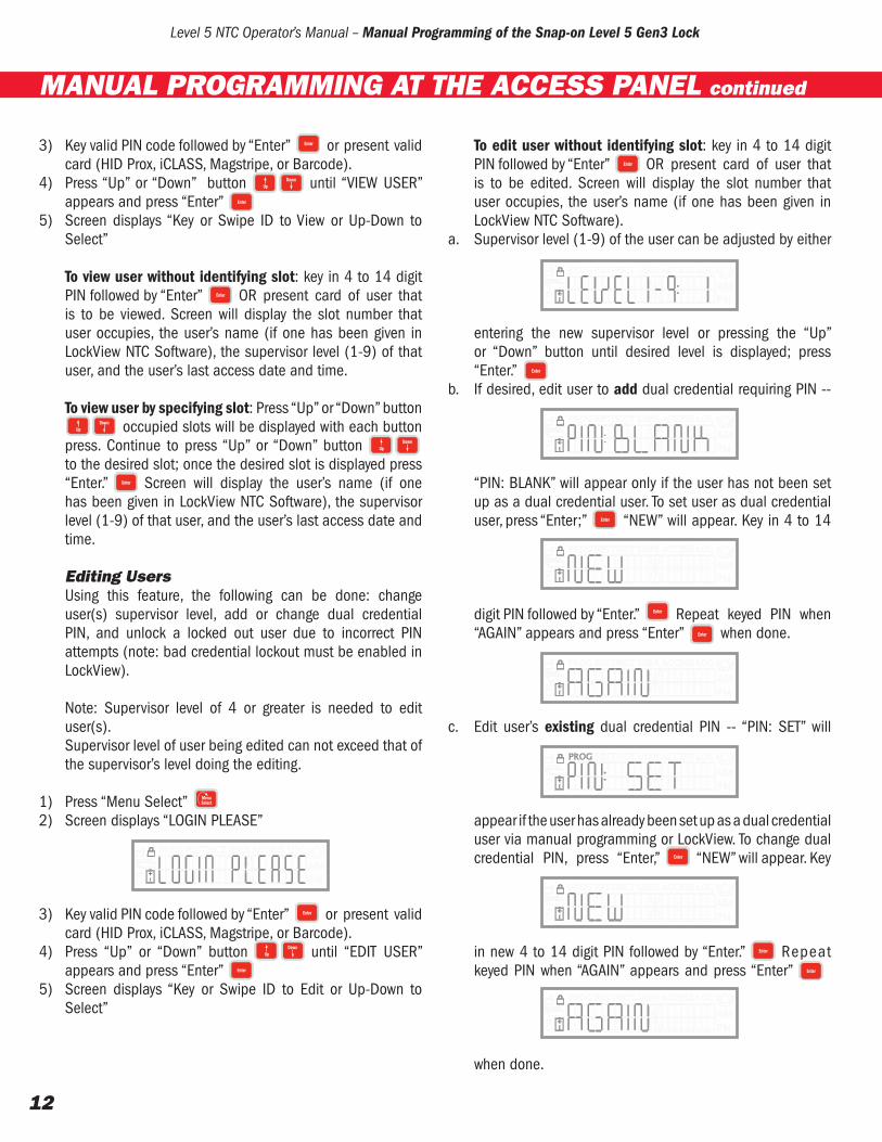
To edit user without identifying slot: key in 4 to 14 digit PIN followed by “Enter” OR present card of user that is to be edited. Screen will display the slot number that user occupies, the user’s name (if one has been given in LockView NTC Software).
a. Supervisor level (1-9) of the user can be adjusted by either
entering the new supervisor level or pressing the “Up” or “Down” button until desired level is displayed; press “Enter.”
b. If desired, edit user to add dual credential requiring PIN --
“PIN: BLANK” will appear only if the user has not been set up as a dual credential user. To set user as dual credential user, press “Enter;” “NEW” will appear. Key in 4 to 14
digit PIN followed by “Enter.” Repeat keyed PIN when “AGAIN” appears and press “Enter” when done.
c. Edit user’s existing dual credential PIN -- “PIN: SET” will
appear if the user has already been set up as a dual credential user via manual programming or LockView. To change dual credential PIN, press “Enter,” “NEW” will appear. Key
in new 4 to 14 digit PIN followed by “Enter.” Repeat keyed PIN when “AGAIN” appears and press “Enter”
when done.
MANUAL PROGRAMMING AT THE ACCESS PANEL continued

Level 5 NTC Operator’s Manual – Manual Programming of the Snap-on Level 5 Gen3 Lock
13
d. If a user’s credential has been locked out, “LOCKEDOUT”
appears. Note: A user’s dual credential (if enabled) can become locked out only if: 1) bad credential lockout has been selected in LockView NTC Software under Lock Editor tab of Read/Write Lock, and 2) the number of incorrect attempts of the dual credential user’s 2nd PIN within the specified time has occurred at the lock. Press “Up or “Down” button to unlock the credential. “Not LOCKOUT”
will appear; press “Enter.”
To edit user by specifying slot: press “Up” or “Down” buttonoccupied slots will be displayed with each button
press. Continue to press “Up” or “Down” button t o the desired slot; once the desired slot is displayed press “Enter.” Screen will display the user’s name (if one has been given in LockView).
a. Supervisor level (1-9) of the user can be adjusted by either
entering the new supervisor level or pressing the “Up” or “Down” button until desired level is displayed; press “Enter.”
b. If desired, edit user to add dual credential requiring PIN -- “PIN: BLANK” will appear only if the user has not been
set up as a dual credential user in LockView NTC Software. To set user as dual credential user, press “Enter;” “NEW” will appear. Key in 4 to 14 digit PIN followed by
“Enter.” Repeat keyed PIN when “AGAIN” appears and
press “Enter” when done.
c. Edit user’s existing dual credential PIN -- “PIN: SET” will
appear if the user has already been set up as a dual credential user in manual programming or in LockView NTC Software. To change dual credential PIN, press “Enter,” “NEW” will appear. Key in new 4 to 14 digit PIN followed by
“Enter.”Repeat keyed PIN when “AGAIN” appears and press “Enter”
when done.d. If a user’s credential has been locked out, “LOCKEDOUT”
appears. A user’s dual credential (if enabled) can become locked out only if: 1) bad credential lockout has been selected in LockView NTC Software under Lock Editor tab of Read/Write Lock, and 2) the number of incorrect attempts of the dual credential user’s 2nd PIN within the specified time has occurred at the lock. Press “Up” or “Down” button
to unlock the credential. “Not LOCKOUT” will
appear; press “Enter”
Set PinNote: Any supervisor level (1-9) can manually add or change a dual credential PIN to an existing credential.
1) Press “Menu Select”2) Screen displays “LOGIN PLEASE”
3) Key valid PIN code followed by “Enter” or present valid card (HID Prox, iCLASS, Magstripe, or Barcode).
MANUAL PROGRAMMING AT THE ACCESS PANEL continued

Level 5 NTC Operator’s Manual – Manual Programming of the Snap-on Level 5 Gen3 Lock
14
4) Press “Up” or “Down” button until “SET PIN”
appears and press “Enter.”5) “NEW” will be displayed
6) Key 4 -14 digit PIN and press “Enter” OR to erase an existing PIN that serves as a 2nd credential press “Enter”
again.7) “AGAIN” will be displayed; rekey PIN to confirm and press
“Enter.”
OR to erase an existing PIN that serves as a 2nd credential press “Enter” again.
8) “STORED” will be displayed when PIN has been added OR
“ERASED” will be displayed when the existing PIN has been
erased.
MANUAL PROGRAMMING AT THE ACCESS PANEL continued
ACCESS PANEL PERMISSIONS BY SUPERVISOR LEVELLevel 1 & 2 Level 3 Level 4-8 Level 9Review MessagesSet Pin
View UsersAdjust TiltBeep VolumeReview MessagesSet Pin
New UserErase UserView UserEdit UserAdjust TiltBeep VolumeReview MessagesSet Pin
New UserErase UserView UserEdit UserAdjust TiltBeep VolumeSet ClockUser LogAccess LogReview MessagesSet PinTest Wireless
Firmware 1.076

Level 5 NTC Operator’s Manual – Manual Programming of the Snap-on Level 5 Gen3 Lock
15
Setting Time at the Toolbox lockw Time Zone (North America & GMT times)w Daylight Savings Time (DST)w Year, Month & Dayw Hour, Minute & AM/PM
** AUDIT TRAIL ACCURACY IN LOCKVIEW NTC SOFTWARE REQUIRES CORRECT DATE AND LOCAL TIME. **
Setting the ClockNote: Supervisor level 9 is needed to set the clock
1. Press “Menu Select”2. Screen displays “LOGIN PLEASE”
3. Enter valid PIN code followed by “Enter” or present valid card (HID Prox, iCLASS, Magstripe, or Barcode).
4. Screen displays “NEW USER.” Press “Down” or “Up” button until screen displays “SET CLOCK.” Press “Enter.”
5. Select Time Zone with “Up”/“Down” buttons. Press “Enter.”
6. Select Daylight Savings Time “ON” or “OFF” with “Up”/“Down” buttons. Press “Enter.”
7. Type 2 digit year, month (01-12) & day (01-31). Press “Clear” to go back. Press “Enter” when done to continue.
8. Type hour (01-12), minute (00-60), followed by 1 for AM or 2 for PM. Press “Clear” to go back. Press “Enter” to continue.
Changing Tilt SensitivityThe lock can be set to alarm if the toolbox is moved (see Activating Alarm). Using this feature, the sensitivity of the tilt sensor can be adjusted according to user preference.
Note: Supervisor level of 3 or greater is needed to change tilt sensitivity. Range is 0 to 8.
“0” equals OFF and “8” is most sensitive.
1) Press “Menu Select”2) Screen displays “LOGIN PLEASE”
3) Key valid PIN code followed by “Enter” or present valid card (HID Prox, iCLASS, Magstripe, or Barcode).
4) Press “Up” or “Down” button until “ADJUST TILT”
appears and press “Enter”5) Screen displays “T-SENS 0 – 8:”
6) Tilt sensitivity level can be adjusted by either entering the new sensitivity (0 - 8) on the keypad or pressing the “Up” or “Down” button until desired level is displayed; press “Enter.”
Changing Beep VolumeNote: Supervisor level of 3 or greater is needed to change beep volume. Range is 0 to 9.
“0” equals OFF up to “9” which is the loudest.
1) Press “Menu Select”2) Screen displays “LOGIN PLEASE”
3) Key valid PIN code followed by “Enter” or present valid card (HID Prox, iCLASS, Magstripe, or Barcode).
4) Press “Up” or “Down” button until “BEEPVOLUME”
appears and press “Enter”5) Screen displays “AudVol 0 – 9:”
MANUAL PROGRAMMING – LOCK SETTINGS
Level 5 NTC Operator’s Manual – Manual Programming of the Snap-on Level 5 Gen3 Lock
16
6) Beep volume can be adjusted by either entering the new volume (0 - 9) on the keypad or by pressing the “Up” or “Down” button until desired level is displayed; press “Enter.”
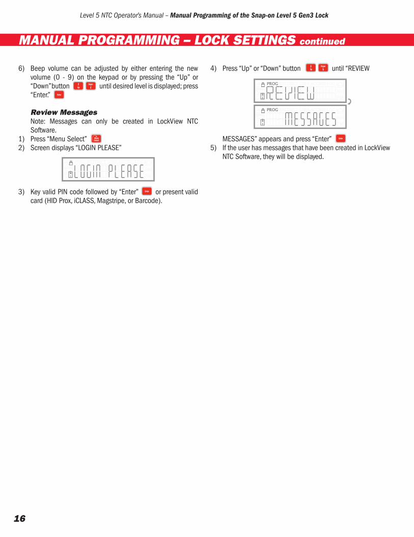
Review MessagesNote: Messages can only be created in LockView NTC Software.
1) Press “Menu Select”2) Screen displays “LOGIN PLEASE”
3) Key valid PIN code followed by “Enter” or present valid card (HID Prox, iCLASS, Magstripe, or Barcode).
4) Press “Up” or “Down” button until “REVIEW
MESSAGES” appears and press “Enter”5) If the user has messages that have been created in LockView
NTC Software, they will be displayed.
MANUAL PROGRAMMING – LOCK SETTINGS continued

Level 5 NTC Operator’s Manual – Manual Programming of the Snap-on Level 5 Gen3 Lock
17
Opening/Closing the Toolbox lock1. Enter valid PIN code followed by “Enter” or present valid
card (HID Prox, iCLASS, Magstripe, or Barcode).2. Toolbox lock will open, Lock icon changes to open and
green OPEN LED will flash. 3. Toolbox lock will automatically lock after open time as set in
LockView has elapsed. Press “Lock” button to lock the toolbox manually.
Activating Tilt Alarm1) To activate the tilt alarm, the unit must be locked2) Press and hold the “Lock” button3) “ARMED” will be displayed and the bell icon will turn on
4) To deactivate the alarm present a valid PIN or card
Test Wi-Fi Network(for wirelessly networked locks)
The signal strength and signal quality of a wirelessly networked lock can be observed.
Note: Supervisor level of 9 is needed to test Wi-Fi network
1) Press “Menu Select”2) Screen displays “LOGIN PLEASE”
3) Key valid PIN code followed by “Enter” or present valid card (HID Prox, iCLASS, Magstripe, or Barcode).
4) Press “Up” or “Down” button until “TEST WIFI
NETWORK” appears and press “Enter”5) “TESTING||||||” will be displayed.
6) “QLTY||||||” will then display the relative signal strength &
quality (more bars equals stronger signal and higher quality).
User LogNote: Supervisor level of 9 is needed to view user log.
User Log provides a means to view all logged entries by user and/or slot number. Information that will be displayed is 1) date/time; 2) action (log in or open) w/ slot number; or 3) user name (if a name was assigned using LockView)
1) Press “Menu Select”2) Screen displays “LOGIN PLEASE”
3) Key valid PIN code followed by “Enter” or present valid card (HID Prox, iCLASS, Magstripe, or Barcode).
USING THE SNAP-ON LEVEL 5 GEN3 LOCK

Level 5 NTC Operator’s Manual – Manual Programming of the Snap-on Level 5 Gen3 Lock
18
4) Press “Up” or “Down” button until “USER LOG”
appears and press “Enter.” 5) Screen displays “Key or Swipe ID to View or Up-Down to
Select”a) To view user log by credential, key PIN code of interest
followed by “Enter” or present card of interest to view most recent logged date/time; action (log in or open) w/ slot number; and user name (if assigned using LockView software)
ORb) To view user log by slot number, press “Up” or “Down”
button to view by slot; once slot number of interest is displayed, press “Enter” to view most recent logged date/time; action (log in or open) w/ slot number
6) To view other logged entries of the same user, press “Up” / “Down” buttons.
Access LogNote: Supervisor level of 9 is needed to view access log
Access Log provides a means to view all logged entries for the lock. Information that will be displayed is 1) date/time; 2) action (log in or open) w/ slot number; or 3) user name (if a name was assigned using LockView)
All logged entries pertaining to each of the above 3 criteria can be viewed individually by pressing “Enter” when the entry of interest appears.
1) Press “Menu Select”2) Screen displays “LOGIN PLEASE”
3) Key valid PIN code followed by “Enter” or present valid card (HID Prox, iCLASS, Magstripe, or Barcode).
4) Press “Up” or “Down” button until “ACCESS LOG”
appears and press “Enter”5) Screen displays and scrolls the most recent logged date/
time; action (log in or open) w/ slot number; and user name (if assigned using LockView NTC Software)
6) To view specific logged entry criteria, press “Enter” button when the criteria of interest is displayed.
7) Press “Up” / “Down” button to scroll through the specific logged entries.
Visual Inventory StatusVisual inventory status of the tool box contents can be recorded at the lock. There are two categories:
1) Inventory OK confirms all tools are in the box.
2) Inventory Problem confirms there is an issue that needs to
be documented.
A numeric code can be created and entered for either status category, which can then be cross referenced with a company-created chart or list that may include such inventory items as tools, drawers, fixtures, etc.
For example, when the second shift mechanic takes control of the tool box shared with the first shift mechanic, entering a code of 020399 could mean that a 5/8” open end wrench that normally resides in drawer 02; (020399) foam location 03; (020399) is missing 99; (020399).
The inventory status will be stored in and become a part of the audit trail in LockView NTC Software.
USING THE SNAP-ON LEVEL 5 GEN3 LOCK continued

Level 5 NTC Operator’s Manual – Manual Programming of the Snap-on Level 5 Gen3 Lock
19
Note: Lock must be locked before continuing.
1) Key valid PIN or present valid card2) Press and HOLD “Back” 3) “LOG: INV OK” will be displayed
4) Press “Up” or “Down” button to toggle between “LOG: INV OK”
and “LOG: PROBLEM”
5) Enter a numeric code between 1 and 14 characters long; OR press “Enter” if a code is not needed.
After one or more digits have been entered, pressing the “Up” button will enter a dash ( - ) and/or pressing the “Down” button will enter a period ( . )
Each dash and/or period count toward the 14 available spaces.
6) Press “Enter” button when finished entering code.
Access Panel DisplaySeveral pieces of information can be obtained by pressing the “Down” button when the unit is in the locked state
1) Date/time
2) Remaining battery charge.
USING THE SNAP-ON LEVEL 5 GEN3 LOCK continued

Level 5 NTC Operator’s Manual – Manual Programming of the Snap-on Level 5 Gen3 Lock
20
USING THE SNAP-ON LEVEL 5 GEN3 LOCK continued
If unit is under AC power, fast charge (FAST-CHG) or slow charge (SLOW-CHG) is displayed.
3) Card reader type (Prox, Magstripe, Barcode, No reader) (Note: HID Prox and iCLASS both show “Prox.”)
4) Lock serial number
5) Control module firmware version
6) Access panel firmware version

MANUALLY PROGRAMMING THE SNAP-ON LEVEL 5 GEN 3 LOCK Instruction Manual
Level 5 NTC
Copyright 2011 © CompX Security Products Any companies and/or products referred to herein are marks or registered trademarks of their respective companies, owners and/or mark holders.


