36
MTL F809F-Plus FOUNDATION TM fieldbus diagnostics module INM F809F-Plus Rev 3 Instruction manual MTL fieldbus networks DRAFT - 02 March 2017 March 2017

MTL F809F-PlusFOUNDATIONTM fieldbus diagnostics module
INM F809F-Plus Rev 3
Instruction manualMTL fieldbus networks
DRAFT - 02 March 2017
March 2017

ii INM F809F-Plus Rev 3
DRAFT - 02 March 2017
DECLARATION OF CONFORMITY
A printed version of the Declaration of Conformity has been provided separately within the original shipment of goods. However, you can find a copy of the latest version at -
http://www.mtl-inst.com/certificates

iiiINM F809F-Plus Rev 3
DRAFT - 02 March 2017 DRAFT - 02 March 2017
CONTENTS
DECLARATION OF CONFORMITY . . . . . . . . . . . . . . . . . . . . . . . . . . . . . . . . . . . . . . . . . . . . . . . . . . . . . ii
GENERAL INFORMATION . . . . . . . . . . . . . . . . . . . . . . . . . . . . . . . . . . . . . . . . . . . . . . . . . . . . . . . . .iv - v
1 OVERVIEW . . . . . . . . . . . . . . . . . . . . . . . . . . . . . . . . . . . . . . . . . . . . . . . . . . . . . . . . . . . . . . . . . . . . . . . . 1
1.1 Components and accessories . . . . . . . . . . . . . . . . . . . . . . . . . . . . . . . . . . . . . . . . . . . . . . . . . . . . . . . . . . . . . .1
2 INSTALLATION . . . . . . . . . . . . . . . . . . . . . . . . . . . . . . . . . . . . . . . . . . . . . . . . . . . . . . . . . . . . . . . . . . . . . 22.1 Mounting . . . . . . . . . . . . . . . . . . . . . . . . . . . . . . . . . . . . . . . . . . . . . . . . . . . . . . . . . . . . . . . . . . . . . . . . . . . . . . .22.2 Power requirements . . . . . . . . . . . . . . . . . . . . . . . . . . . . . . . . . . . . . . . . . . . . . . . . . . . . . . . . . . . . . . . . . . . . . .32.3 Configuration of fieldbus communication segment . . . . . . . . . . . . . . . . . . . . . . . . . . . . . . . . . . . . . . . . . . . .32.4 Installation for communication on separate fieldbus segment . . . . . . . . . . . . . . . . . . . . . . . . . . . . . . . . . . .4
2.4.1 Interconnection via carrier . . . . . . . . . . . . . . . . . . . . . . . . . . . . . . . . . . . . . . . . . . . . . . . . . . . . . . . . . . . . . . .42.4.2 Interconnection via top connector . . . . . . . . . . . . . . . . . . . . . . . . . . . . . . . . . . . . . . . . . . . . . . . . . . . . . . . . .52.4.3 Fieldbus segment design rules . . . . . . . . . . . . . . . . . . . . . . . . . . . . . . . . . . . . . . . . . . . . . . . . . . . . . . . . . . . .62.4.4 Diagnostics module power supply . . . . . . . . . . . . . . . . . . . . . . . . . . . . . . . . . . . . . . . . . . . . . . . . . . . . . . . . .62.4.5 Diagnostics module segment termination . . . . . . . . . . . . . . . . . . . . . . . . . . . . . . . . . . . . . . . . . . . . . . . . . .6
2.5 Ground Reference Switches . . . . . . . . . . . . . . . . . . . . . . . . . . . . . . . . . . . . . . . . . . . . . . . . . . . . . . . . . . . . . . .6
3 CONFIGURATION . . . . . . . . . . . . . . . . . . . . . . . . . . . . . . . . . . . . . . . . . . . . . . . . . . . . . . . . . . . . . . . . . . . 73.1 Standard . . . . . . . . . . . . . . . . . . . . . . . . . . . . . . . . . . . . . . . . . . . . . . . . . . . . . . . . . . . . . . . . . . . . . . . . . . . . . . .73.2 F809F-Plus Configuration . . . . . . . . . . . . . . . . . . . . . . . . . . . . . . . . . . . . . . . . . . . . . . . . . . . . . . . . . . . . . . . . . .7
4 BLOCK CONFIGURATION . . . . . . . . . . . . . . . . . . . . . . . . . . . . . . . . . . . . . . . . . . . . . . . . . . . . . . . . . . . . 84.1 Resource Block . . . . . . . . . . . . . . . . . . . . . . . . . . . . . . . . . . . . . . . . . . . . . . . . . . . . . . . . . . . . . . . . . . . . . . . 8-10
4.1.1 Diagnostic Bits . . . . . . . . . . . . . . . . . . . . . . . . . . . . . . . . . . . . . . . . . . . . . . . . . . . . . . . . . . . . . . . . . . . . . 10-114.1.2 Block errors . . . . . . . . . . . . . . . . . . . . . . . . . . . . . . . . . . . . . . . . . . . . . . . . . . . . . . . . . . . . . . . . . . . . . . . . . . .114.1.3 Modes . . . . . . . . . . . . . . . . . . . . . . . . . . . . . . . . . . . . . . . . . . . . . . . . . . . . . . . . . . . . . . . . . . . . . . . . . . . . . . .11
4.2 Transducer Blocks . . . . . . . . . . . . . . . . . . . . . . . . . . . . . . . . . . . . . . . . . . . . . . . . . . . . . . . . . . . . . . . . . . . . . . .124.2.1 Transducer Block Errors . . . . . . . . . . . . . . . . . . . . . . . . . . . . . . . . . . . . . . . . . . . . . . . . . . . . . . . . . . . . . . . .124.2.2 Transducer Block Modes . . . . . . . . . . . . . . . . . . . . . . . . . . . . . . . . . . . . . . . . . . . . . . . . . . . . . . . . . . . . . . . .124.2.3 Transducer Block Alarm Detection . . . . . . . . . . . . . . . . . . . . . . . . . . . . . . . . . . . . . . . . . . . . . . . . . . . . . . . .134.2.4 System Transducer Block (SysTB) . . . . . . . . . . . . . . . . . . . . . . . . . . . . . . . . . . . . . . . . . . . . . . . . . . . . . 13-15
4.2.4.1 System alarms . . . . . . . . . . . . . . . . . . . . . . . . . . . . . . . . . . . . . . . . . . . . . . . . . . . . . . . . . . . . . . . . . . .164.2.4.2 Self test alarms . . . . . . . . . . . . . . . . . . . . . . . . . . . . . . . . . . . . . . . . . . . . . . . . . . . . . . . . . . . . . . . . . .164.2.4.3 Methods . . . . . . . . . . . . . . . . . . . . . . . . . . . . . . . . . . . . . . . . . . . . . . . . . . . . . . . . . . . . . . . . . . . . . . . .17
4.2.5 Segment Transducer Block (SegTB) . . . . . . . . . . . . . . . . . . . . . . . . . . . . . . . . . . . . . . . . . . . . . . . . . . . . 17-204.2.5.1 SEGMENT_ALARMS - Descriptions and Corrective Actions . . . . . . . . . . . . . . . . . . . . . . . . . . . 21-224.2.5.2 DEVICE_ALARMS - Descriptions and Corrective Actions . . . . . . . . . . . . . . . . . . . . . . . . . . . . . . . .224.2.5.3 DEVICE_ALERTS - Descriptions . . . . . . . . . . . . . . . . . . . . . . . . . . . . . . . . . . . . . . . . . . . . . . . . . . . . .22
4.3 Discrete Input Block . . . . . . . . . . . . . . . . . . . . . . . . . . . . . . . . . . . . . . . . . . . . . . . . . . . . . . . . . . . . . . . . . . . . .234.3.1 Discrete Input Block Errors . . . . . . . . . . . . . . . . . . . . . . . . . . . . . . . . . . . . . . . . . . . . . . . . . . . . . . . . . . . . . .23
5 OPERATION AND MAINTENANCE . . . . . . . . . . . . . . . . . . . . . . . . . . . . . . . . . . . . . . . . . . . . . . . . . . . . 245.1 LED indicators . . . . . . . . . . . . . . . . . . . . . . . . . . . . . . . . . . . . . . . . . . . . . . . . . . . . . . . . . . . . . . . . . . . . . . . . . .245.2 FOUNDATIONTM fieldbus Information . . . . . . . . . . . . . . . . . . . . . . . . . . . . . . . . . . . . . . . . . . . . . . . . . . . . . . . . .24
5.2.1 Commissioning (Addressing) . . . . . . . . . . . . . . . . . . . . . . . . . . . . . . . . . . . . . . . . . . . . . . . . . . . . . . . . . . . .245.3 Hardware Maintenance . . . . . . . . . . . . . . . . . . . . . . . . . . . . . . . . . . . . . . . . . . . . . . . . . . . . . . . . . . . . . . . . . .24
5.3.1 Communication/Power Check . . . . . . . . . . . . . . . . . . . . . . . . . . . . . . . . . . . . . . . . . . . . . . . . . . . . . . . . . . . .245.3.2 Resetting the Configuration (RESTART) . . . . . . . . . . . . . . . . . . . . . . . . . . . . . . . . . . . . . . . . . . . . . . . . . . . .24
5.4 Troubleshooting . . . . . . . . . . . . . . . . . . . . . . . . . . . . . . . . . . . . . . . . . . . . . . . . . . . . . . . . . . . . . . . . . . . . . . . .25
5.4.1 FOUNDATIONTM fieldbus. . . . . . . . . . . . . . . . . . . . . . . . . . . . . . . . . . . . . . . . . . . . . . . . . . . . . . . . . . . . . . . . . . .25
5.4.2 Resource Block . . . . . . . . . . . . . . . . . . . . . . . . . . . . . . . . . . . . . . . . . . . . . . . . . . . . . . . . . . . . . . . . . . . . . . . .25
5.4.3 System and Segment Transducer Block Troubleshooting . . . . . . . . . . . . . . . . . . . . . . . . . . . . . . . . . . . . .25
APPENDIX A: Troubleshooting Table . . . . . . . . . . . . . . . . . . . . . . . . . . . . . . . . . . . . . . . . . . . . . . . . . . . . . 26-27

iv INM F809F-Plus Rev 3
DRAFT - 02 March 2017
GENERAL INFORMATION
NOTE This manual applies to Diagnostic Module F809F-Plus version MT03. The version number is indicated on
the module’s side label.
For F809F versions MT01 and MT02, refer to instruction manuals INM F809F-1 or INM F809F-2C, which are available to download from the MTL website.
Safety instructions for installation and operating personnel
These operating instructions contain basic safety instructions for installation, operation and maintenance and servicing. Failure to comply with these instructions can endanger personnel, the plant and the environment.
Before installation/commissioning: • Read the operating instructions.
• Give adequate training to the installation and operating personnel.
• Ensure that the contents of the operating instructions are fully understood by responsible personnel.
• The national installation and mounting regulations (e.g. EN 60079-14) apply.
When operating the devices:
• Make the operating instructions available at the installation area (at all times).
• Observe safety instructions.
• Observe national safety and accident prevention regulations.
• Operate the equipment within its published specification.
• Servicing/maintenance work or repairs which are not described in the operating instructions must not be performed without prior agreement with the manufacturer.
• Any damage may render hazardous-area protection null and void.
• No changes to the devices or components impairing their hazardous-area protection are permitted.
• The device may only be fitted and used if it is in an undamaged, dry and clean state.
If there are any points that remain unclear:
• Contact your local Eaton Office
• Product and contact details are also available from the company website: http://www.mtl-inst.com
Consignes de sécurité pour le personnel d’installation et le personnel d’exploitation
Ces consignes d’exploitation renferment les consignes de sécurité de base pour l’installation, l’exploitation la mai tenance et les services Ne pas se conformer à ces consignes peut mettre en danger le personnel, l’usine et l’environnement.
Avant l’installation et la première mise en service : • Lire les consignes d’exploitation
• Fournir la formation appropriée aux personnels d’installation, et d’exploitation
• S’assurer que le contenu des consignes d’exploitation est pleinement assimilé par le personnel responsable
• Appliquer les règlements nationaux en vigueur pour l’installation et le montage (par ex. NE 60079-14)

vINM F809F-Plus Rev 3
DRAFT - 02 March 2017 DRAFT - 02 March 2017
Au cours de l’exploitation des appareils:
• Faire en sorte que les consignes d’exploitation soient à disposition sur la zone d’installation (à tous moments)
• Observe safety instructions.
• Observer les consignes de sécurité.
• Observer les règlements nationaux de sécurité et de prévention des accidents
• Exploiter l’équipement dans les limites de sa spécification publiée
• Les travaux de service/maintenance ou les réparations non décrits dans les consignes ne doivent pas être exécutés sans l’agrément préalable du fabricant.
• Tout endommagement peut rendre caduque la protection en zone dangereuse
• Aucune modification apportée à l’appareil ou aux composants, portant atteinte à leur protection en zone dangereuse, ne sera autorisée
• L’appareil ne peut être utilisé que s’il se trouve dans un état non endommagé, sec et propre.
S’il reste quelques points à éclaircir :
• Contactez votre bureau Eaton local
• Les détails sur les produits et les contacts sont également disponibles à partir du site de la compagnie http://www.mtl-inst.com
NOTEThe F809F-Plus should only be fitted to a carrier whose low voltage DC power is derived
from a power supply compliant with EN61010 or EN60950 double or reinforced insulation.
The F809F-Plus has an extended operating temperature range. Cabling connected to it should be rated in accordance with maximum and minimum ambient temperatures expected
FOR US AND CANADA:
THIS EQUIPMENT IS SUITABLE FOR USE IN CLASS1, DIVISION 2, GROUPS A, B, C, D AND CLASS 1, ZONE 2, GROUP IIC OR NON-HAZARDOUS LOCATIONS ONLY.
WARNING/AVERTISSEMENT
EXPLOSION HAZARD - SUBSTITUTION OF COMPONENTS MAY IMPAIR SUITABILITY FOR CLASS 1, DIVISION 2.
RISQUE D’EXPLOSION - LA SUBSTITUTION DE COMPOSANTS PEUT RENDRE CE MATERIEL INACCEPTABLE POUR LES EMPLACEMENTS DE CLASS 1, DIVISION2
WARNING/AVERTISSEMENT
EXPLOSION HAZARD - DO NOT DISCONNECT EQUIPMENT UNLESS POWER HAS BEEN SWITCHED OFF OR THE AREA IS KNOWN TO BE NON-HAZARDOUS
RISQUE D’EXPLOSION - AVANT DE DECONNECTER L’EQUIPEMENT, COUPER LE COURANT OU S’ASSURER QUE L’EMPLACEMENT EST DESIGNE NON DANGEREUX.

vi INM F809F-Plus Rev 3
DRAFT - 02 March 2017
this page is left intentionally blank

1INM F809F-Plus Rev 3
DRAFT - 02 March 2017 DRAFT - 02 March 2017
1 OVERVIEWThe F809F-Plus Fieldbus Diagnostic Module is available as an option for use with 918x Series, F800 Series and some F600 Series fieldbus power supplies. It plugs into a 918x, F8xx or F6x8 Series power supply carrier, or an F8x8 diagnostic module carrier and monitors the performance of each of the eight fieldbus segments, providing information on the network health and capturing retransmissions between the fieldbus devices and control system.
The parameters measured include the bulk power supply input voltage, temperature, segment voltages and signal levels of all devices. Average and peak noise are measured in each of three frequency bands. Additionally the monitor checks for correct bus termination and for short-circuits between the fieldbus signal wires and cable shields. Retransmissions are also measured. The measured physical layer parameters are used to predict the corrective action required. This allows problems to be rectified before poor network health results in devices being removed from the ‘live list’, which could affect the operation of the plant. Measurements may alternatively be captured and sent to off-site experts for interpretation.
The F809F-Plus is a FOUNDATIONTM fieldbus device, and communicates with the host control system via a fieldbus segment. This allows the network status and measured parameters to be displayed in the instrument management software on the host control system.
1.1 Components and accessoriesThis manual is designed to assist in the installation, configuration and maintenance of the F809F-Plus Fieldbus Diagnostic Module version MT03 (see side label), as explained on the opposite page under General Information.
For product specification see the EPS F809F-Plus data sheet.
Features of this version include:
• Superior immunity to noise on the ‘communicating’ segment – continues to report diagnostic information in electrically noisy environments.
• Enhanced short-to-shield detection, including wider choice of ground reference options and immunity to interference from mains-connected Emerson 375 and 475 communicators.
• Extended measurement range for fieldbus power supply voltage – compatible with full range of MTL power supply types.
• Registered to Fieldbus Foundation ITK 6.0, including field diagnostic bits according to NAMUR NE107 recommendations.
• Support for fully updated eEDDL and DTM user interfaces.
MTL F809F-Plus Diagnostics module

2 INM F809F-Plus Rev 3
DRAFT - 02 March 2017
2 INSTALLATION The F809F-Plus is designed for carrier mounting and may be mounted on any 918x, MTL F8xx or F6x8 series carrier. See the MTL 918x, F8xx or F6x8 series power supply or F8x8 carrier installation manual for details of how these carriers are installed.
The F809F-Plus Fieldbus Diagnostic Monitor receives redundant power feeds and connections to the eight monitored fieldbus segments via the carrier. The diagnostic information is conveyed to the controlling host via a fieldbus segment and the user has the choice of segment 1 or 8 (of the segments being monitored), or a totally separate segment of their choosing. The segment chosen for communication is configured using a plugin connector located on the front edge of the module.
2.1 MountingAlign the F809F-Plus module with the two multi-pin connectors* on the carrier and hold it in place while tightening the two captive fixing screws.
NOTEThe fixing screws should be tightened to a minimum torque value of 1.2Nm, but
should not exceed a torque value of 1.5Nm.
To remove the F809F-Plus, support the module while unscrewing the two fixingscrews at its base. Lift the module off the carrier connector.
* A third connector is provided on the module for factory testing and firmware upgrade. This connector, the largest of the three, is not used on the carrier and is identified on the F809F-Plus side label. See Figure 2.1.
Figure 2.1: Unused connector
Figure 2.2: Configuration “comb”
3INM F809F-Plus Rev 3
DRAFT - 02 March 2017 DRAFT - 02 March 2017
2.2 Power requirementsAn F809F-Plus module draws approximately 15mA from the communicating fieldbus segment. This needs to be included when calculating the total design current requirement for that segment.
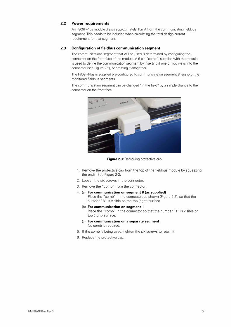
2.3 Configuration of fieldbus communication segmentThe communications segment that will be used is determined by configuring the connector on the front face of the module. A 6-pin “comb”, supplied with the module, is used to define the communication segment by inserting it one of two ways into the connector (see Figure 2-2), or omitting it altogether.
The F809F-Plus is supplied pre-configured to communicate on segment 8 (eight) of the monitored fieldbus segments.
The communication segment can be changed “in the field” by a simple change to the connector on the front face.
1. Remove the protective cap from the top of the fieldbus module by squeezing the ends. See Figure 2-3.
2. Loosen the six screws in the connector.
3. Remove the “comb” from the connector.
4. (a) For communication on segment 8 (as supplied) Place the “comb” in the connector, as shown (Figure 2-2), so that the number “8” is visible on the top (right) surface.
(b) For communication on segment 1 Place the “comb” in the connector so that the number “1” is visible on top (right) surface.
(c) For communication on a separate segment No comb is required.
5. If the comb is being used, tighten the six screws to retain it.
6. Replace the protective cap.
Figure 2.3: Removing protective cap

4 INM F809F-Plus Rev 3
DRAFT - 02 March 2017
2.4 Installation for communication on separate fieldbus segmentIf a separate fieldbus segment is the chosen option, then it can communicate the diagnostic data via the top connector on the F809F-Plus or, in some cases, through dedicated connectors on the carrier. The table below shows which carriers (by batch code) provide this option.
Carrier typeDiagnostic data connection options
via carrier via top connector
F618D-CL All All
F860-CA None All
F880-CR-xx None All
F880-CL-xx None All
F880-CA-xx 0727 or later All
F888-CA-xx All All
F890-CA-xx 0727 or later All
F892-CA-xx 0727 or later All
F898-CA-xx918x-CA-Px
AllAll
AllAll
2.4.1 Interconnection via carrierFigure 2-4 shows how a dedicated diagnostic segment, comprising multiple F6x8, F8xx or 918x carriers, is interlinked, powered and terminated. Where carriers are installed in vertical columns, connect the H1+, H1- and S terminals of adjacent carriers as shown.
Figure 2.4: Carrier linking

5INM F809F-Plus Rev 3
DRAFT - 02 March 2017 DRAFT - 02 March 2017
2.4.2 Interconnection via top connectorFigure 2-5 shows how a dedicated diagnostic segment comprising multiple F8xx carriers is interlinked and terminated.
The fieldbus spur is connected to the two middle terminals in the top connector - see Figures 2-2 and 2-6.
�����������
������������������
�������������������
�
�����������
�
�������������������
�
�����
�
�
�
�
�
�
�
�
��
�
�����
���������������������
���������������������
������
����������������
�������������������
Figure 2.5: Module connector linking
Figure 2.6: Connector wiring

6 INM F809F-Plus Rev 3
DRAFT - 02 March 2017
2.4.3 Fieldbus segment design rulesA segment may support a number of F809F-Plus modules. The actual number is based on a number of factors:
• the logical device limit of the host,
• the fieldbus power supply capacity,
• operational constraints such as bandwidth
• the overall impact on the system if that diagnostic segment should be lost.
Shielded, twisted-pair cable, complying with FOUNDATIONTM fieldbus ‘Type A’ construction is recommended for the diagnostic segment. Unshielded instrument cable is suitable for short interconnections between adjacent carriers.
2.4.4 Diagnostics module power supplyThe diagnostic segment must be powered by a conditioned fieldbus power supply (see Figure 2-4 & 2-5) that will provide a voltage in the range 9–32V DC at each F809F-Plus fieldbus diagnostic module. This power supply may be either simplex or redundant, depending on the application, and be capable of providing sufficient current for the entire diagnostic segment.
Each F809F-Plus module draws approximately 15mA, so a segment comprising 10 F809F-Plus modules, for example, will require an output current of at least 150mA. Suitable multi-segment redundant fieldbus power supplies include MTL 918x-x1 and F8x0. Type FPS-I may be selected where a single-segment redundant power supply is preferred. Alternatively, if a non-redundant power supply is acceptable, suitable types include F101, F102 and FPS-DT.
2.4.5 Diagnostics module segment terminationAs with all Fieldbus segments, the one used for the diagnostic data must be terminated at both ends to maintain the bus impedance within FOUNDATIONTM fieldbus limits. When interconnections are via the carrier, a terminator must be connected between the H1+ and H1- terminals of the diagnostic bus connector at the far end of the segment (see Figure 2-4). Suitable terminators for this are MTL type FBT1-IS or F100.
When F809F-Plus modules are interconnected by means of the top connector, it is preferable to connect each module to the spur of a Megablock device coupler. This protects the diagnostic segment against a short-circuit on any spur. A Megablock with a built-in terminator should be selected. Termination of the bus at the host end may be provided either by an integrated terminator within the power supply or by means of a separate terminator.
2.5 Ground Reference SwitchesSwitches are provided on the side of the F809F-Plus module to select different grounding options - see Figure 2.7. The switch positions are chosen according to the type of MTL Fieldbus Power Supply with which the F809F-Plus is being used, as described in the following table:
Switch A position Switch B position Fieldbus power supply type
0 0 Invalid configuration - do not select
0 1 All F8xx Series except F860
1 0 F618D
1 1 All 918x Series and F860

7INM F809F-Plus Rev 3
DRAFT - 02 March 2017 DRAFT - 02 March 2017
A separate case ground terminal is provided (Figure 2-8) to enable the case of the module to be linked to a ground terminal on the circuit board.
3 CONFIGURATION
3.1 StandardEach FOUNDATIONTM fieldbus configuration tool or host system has a different way of displaying and performing configurations. Some will use Device Descriptions (DDs) and DD Methods to make configuration and displaying of data consistent across host platforms.
Refer to the fieldbus control system’s documentation to perform configuration changes using a FOUNDATIONTM fieldbus host or configuration tool.
The function of the F809F-Plus is to provide diagnostic data, therefore configuration changes can be made with the MODE_BLK.ACTUAL in AUTO, MANUAL or Out Of Service (OOS) mode.
NOTE
Fieldbus devices used in process applications usually have to be set to OOS mode before making configuration changes.
3.2 F809F-Plus ConfigurationThe F809F-Plus is available with the standard configuration setting. The configuration settings and block configuration may be changed in the field with the FOUNDATIONTM fieldbus host or a configuration tool.
Figure 2.7: Ground reference switches Figure 2.8: Case ground terminal

8 INM F809F-Plus Rev 3
DRAFT - 02 March 2017
4 BLOCK CONFIGURATION
4.1 Resource BlockThe resource block defines the physical resources of the device including type of measurement, memory, etc. The resource block also defines functionality, such as shed times, that is common across multiple blocks. The block has no linkable inputs or outputs and it performs memory-level diagnostics.
Table 4.1: Resource block parameters
Number Parameter Description
00 BLOCK
01 ST_REV The revision level of the static data associated with the function block.
02 TAG_DESC
03 STRATEGY The strategy field can be used to identify grouping of blocks.
04 ALERT_KEY The identification number of the plant unit.
05 MODE_BLK The ACTUAL, TARGET, PERMITTED, and NORMAL modes of the block. For further description, see the Mode parameter formal model in FF-890.
06 BLOCK_ERR This parameter reflects the error status associated with the hardware or software components associated with a block. Multiple errors may be shown. For a list of enumeration values, see FF-890, Block_Err formal model.
07 RS_STATE State of the function block application state machine. For a list of enumeration values, see FF-890.
08 TEST_RW Read/write test parameter - used only for conformance testing.
09 DD_RESOURCE String identifying the tag of the resource which contains the Device Description for the resource.
10 MANUFAC_ID Manufacturer identification number - used by an interface device to locate the DD file for the resource.
11 DEV_TYPE Manufacturer’s model number associated with the resource - used by interface devices to locate the DD file for the resource.
12 DEV_REV Manufacturer revision number associated with the resource - used by an interface device to locate the DD file for the resource.
13 DD_REV Revision of the DD associated with the resource - used by the interface device to locate the DD file for the resource.
14 GRANT_DENY Options for controlling access of host computer and local control panels to operating, tuning and alarm parameters of the block.
15 HARD_TYPES The types of hardware available as channel numbers. The supported hardware type is: SCALAR_INPUT
16 RESTART Allows a manual restart to be initiated. See also Section 5.4.2
17 FEATURES Used to show supported resource block options. The supported features are: SOFT_WRITE_LOCK_SUPPORT and REPORTS.
18 FEATURE_SEL Used to select resource block options.
19 CYCLE_TYPE Identifies the block execution methods available for this resource. The supported cycle types are: SCHEDULED, and COMPLETION_OF_BLOCK_EXECUTION.
20 CYCLE_SEL Used to select the block execution method for this resource.
21 MIN_CYCLE_T Time duration of the shortest cycle interval of which the resource is capable.
22 MEMORY_SIZE Available configuration memory in the empty resource. To be checked before attempting a download.
23 NV_CYCLE_T Minimum time interval specified by the manufacturer for writing copies of NV parameters to non-volatile memory. Zero means it will never be automatically copied. At the end of NV_CYCLE_T, only those parameters which have changed need to be updated in NVRAM.
24 FREE_SPACE Percent of memory available for further configuration. Zero in preconfigured resource.
25 FREE_TIME Percent of the block processing time that is free to process additional blocks.
26 SHED_RCAS Time duration at which to give up on computer writes to function block RCas locations. Shed from RCas will never happen when SHED_RCAS = 0.
27 SHED_ROUT Time duration at which to give up on computer writes to function block ROut locations. Shed from ROut will never happen when SHED_ROUT = 0.
28 FAULT_STATE Condition set by loss of communication to an output block, fault promoted to an output block or physical contact. When faultstate condition is set, then output function blocks will perform their FSTATE actions.
continued

9INM F809F-Plus Rev 3
DRAFT - 02 March 2017 DRAFT - 02 March 2017
29 SET_FSTATE Allows the FAIL_SAFE condition to be manually initiated by selecting Set.
30 CLR_FSTATE Writing a Clear to this parameter will clear the device FAIL_SAFE if the field condition has cleared.
31 MAX_NOTIFY Maximum number of unconfirmed notify messages possible.
32 LIM_NOTIFY Maximum number of unconfirmed alert notify messages allowed.
33 CONFIRM_TIME The time the resource will wait for confirmation of receipt of a report before trying again. Retry will not happen when CONFIRM_TIME=0.
34 WRITE_LOCK If set, all writes to static and non-volatile parameters are prohibited, except to clear WRITE_LOCK. Block inputs will continue to be updated.
35 UPDATE_EVT This alert is generated by any change to the static data.
36 BLOCK_ALM The BLOCK_ALM is used for all configuration, hardware, connection failure or system problems in the block. The cause of the alert is entered in the subcode field. The first alert to become active will set the Active status in the Status attribute. As soon as the Unreported status is cleared by the alert reporting task, another block alert may be reported without clearing the Active status, if the subcode has changed.
37 ALARM_SUM The current alert status, unacknowledged states, unreported states, and disabled states of the alarms associated with the function block.
38 ACK_OPTION Selection of whether alarms oscillated with the block will be automatically acknowledged.
39 WRITE_PRI Priority of the alarm generated by clearing the write lock.
40 WRITE_ALM This alert is generated if the write lock parameter is cleared.
41 ITK_VER Major revision number of the interoperability test case used in certifying this device as interoperable. The format and range are controlled by the Fieldbus FOUNDATIONTM.
42 FD_VER The major version of the Field Diagnostics specification used for the development of this device.
43 FD_FAIL_ACTIVE This parameter reflects the error conditions that are being detected as active as selected for the 'Failed' category. It is a bit string, so that multiple conditions may be shown.
44 FD_OFFSPEC_ACTIVE This parameter reflects the error conditions that are being detected as active as selected for the 'Off Specification' category. It is a bit string, so that multiple conditions may be shown.
45 FD_MAINT_ACTIVE This parameter reflects the error conditions that are being detected as active as selected for the 'Maintenance' category. It is a bit string, so that multiple conditions may be shown.
46 FD_CHECK_ACTIVE This parameter reflects the error conditions that are being detected as active as selected for the 'Check Function' category. It is a bit string, so that multiple conditions may be shown.
47 FD_FAIL_MAP This parameter enables or disables conditions to be detected as active for the 'Failed' category
48 FD_OFFSPEC_MAP This parameter enables or disables conditions to be detected as active for the 'Off Specification' category
49 FD_MAINT_MAP This parameter enables or disables conditions to be detected as active for the 'Maintenance' category
50 FD_CHECK_MAP This parameter enables or disables conditions to be detected as active for the 'Check Function' category
51 FD_FAIL_MASK This parameter is used to suppress any single or multiple conditions that are active, in the 'Failed' category, from being broadcasted through the Alarm parameter.
52 FD_OFFSPEC_MASK This parameter is used to suppress any single or multiple conditions that are active, in the 'Off Specification' category, from being broadcasted through the Alarm parameter.
53 FD_MAINT_MASK This parameter is used to suppress any single or multiple conditions that are active, in the 'Maintenance' category, from being broadcasted through the Alarm parameter.
54 FD_CHECK_MASK This parameter is used to suppress any single or multiple conditions that are active, in the 'Check Function' category, from being broadcasted through the Alarm parameter.
55 FD_FAIL_ALM This parameter is used to broadcast a change of an unmasked 'Failed' condition.
56 FD_OFFSPEC_ALM This parameter is used to broadcast a change of an unmasked 'Off Specification' condition.
57 FD_MAINT_ALM This parameter is used to broadcast a change of an unmasked 'Maintenance' condition.
58 FD_CHECK_ALM This parameter is used to broadcast a change of an unmasked 'Check Function' condition.
59 FD_FAIL_PRI This parameter allows the user to specify the priority of the 'Failed' Alarm category.
60 FD_OFFSPEC_PRI This parameter allows the user to specify the priority of the 'Off Specification' Alarm category.
61 FD_MAINT_PRI This parameter allows the user to specify the priority of the 'Maintenance' Alarm category.
62 FD_CHECK_PRI This parameter allows the user to specify the priority of the 'Check Function' Alarm category.
continued

10 INM F809F-Plus Rev 3
DRAFT - 02 March 2017
63 FD_SIMULATE When simulation is enabled the Field Diagnostics conditions are taken from 'Diagnostic Simulate Value' otherwise the conditions are taken from 'Diagnostic Value'.
64 FD_RECOMMEN_ACT This parameter is a device enumerated summarization of the most severe condition or conditions detected. The DD should describe by enumerated action, what should be done to alleviate the condition or conditions.
65 IDENTIFICATION_ MEASUREMENT
(PRODUCT_ID, SERIAL_NUMBER, HW_REVISION, SOFTWARE_VERSION, FIRMWARE_CRC)
Measurement product ID, serial number, hardware revision and software version. View as hexadecimal number.
66 IDENTIFICATION_ FIELDBUS
(SERIAL_NUMBER, HW_REVISION, SOFTWARE_VERSION, FIRMWARE_CRC)
Fieldbus serial number, hardware revision and software version. View as hexadecimal number.
4.1.1 Diagnostic BitsDiagnostic bits permit the aggregation of all device status and diagnostics so that a Host system can integrate this information into its infrastructure.
Four alarm categories as defined by the NAMUR NE-107 specification, Failed, Off-Specification, Maintenance and Check function share 11 conditions. The mapping of these conditions is as follows:
Diagnostic Bit
Condition Description
0 CHECK (Fieldbus Foundation defined condition)
Set if any transducer block has a normal mode other than OOS and the Actual is not Auto
1 “Device Needs Maintenance Soon” bit of the BLOCK_ERR parameter within segment 1 transducer block.
Set if any Segment / Device alarm bits are set within segment 1
2 “Device Needs Maintenance Soon” bit of the BLOCK_ERR parameter within segment 2 transducer block.
Set if any Segment / Device alarm bits are set within segment 2
3 “Device Needs Maintenance Soon” bit of the BLOCK_ERR parameter within segment 3 transducer block.
Set if any Segment / Device alarm bits are set within segment 3
4 “Device Needs Maintenance Soon” bit of the BLOCK_ERR parameter within segment 4 transducer block.
Set if any Segment / Device alarm bits are set within segment 4
5 “Device Needs Maintenance Soon” bit of the BLOCK_ERR parameter within segment 5 transducer block.
Set if any Segment / Device alarm bits are set within segment 5
6 “Device Needs Maintenance Soon” bit of the BLOCK_ERR parameter within segment 6 transducer block.
Set if any Segment / Device alarm bits are set within segment 6
7 “Device Needs Maintenance Soon” bit of the BLOCK_ERR parameter within segment 7 transducer block.
Set if any Segment / Device alarm bits are set within segment 7
continued

11INM F809F-Plus Rev 3
DRAFT - 02 March 2017 DRAFT - 02 March 2017
8 “Device Needs Maintenance Soon” bit of the BLOCK_ERR parameter within segment 8 transducer block.
Set if any Segment / Device alarm bits are set within segment 8
9 “Device Needs Maintenance Soon” bit of the BLOCK_ERR parameter for the system transducer block.
Set if any System Alarm and Self-test fault alarms are set
10 Logical OR of the “Device Needs Maintenance Soon” bits of all 9 transducer blocks
Set if any System, Segment, Device or Self-test alarms are set
4.1.2 Block errorsTable 4-2 lists all conditions in the BLOCK_ERR parameter, with conditions in bold supported by the F809F-Plus.
Table 4.2: BLOCK_ERR conditions
Number Name and Description
0 Other
1 Block Configuration Error
2 Link Configuration Error
3 Simulate Active
4 Local Override
5 Device Fault State Set
6 Device Needs Maintenance Soon
7 Input failure/process variable has bad status
8 Output Failure
9 Memory Failure
10 Lost Static Data: Static data that is stored in non-volatile memory has been lost.
11 Lost NV Data
12 Readback Check Failed
13 Device Needs Maintenance Now
14 Power Up: The device was just powered-up.
15 OOS: The actual mode is out of service.
4.1.3 ModesThe resource block supports two modes of operation as defined by the MODE_BLK parameter:
Automatic (Auto)
The block is processing its normal background memory checks. In this mode, changes can be made to all configurable parameters.
Out of Service (OOS)
The block is not processing its tasks. The BLOCK_ERR parameter shows Out of Service. In this mode, changes can be made to any configurable parameters. The target mode of a block may be restricted to one or more of the supported modes.

12 INM F809F-Plus Rev 3
DRAFT - 02 March 2017
4.2 Transducer BlocksThere are two types of transducer blocks that allow the user to view and manage the channel information. These blocks are:
• System Transducer Block (SysTB) – see “System Transducer Block (SysTB)” in Section 4.2.4.
• Segment Transducer Block (SegTB), one for each of the eight segments – see “Segment Transducer Block (SegTB)” in Section 4.2.5.
These Transducer blocks contain specific diagnostic data.
4.2.1 Transducer Block ErrorsThe following conditions are reported in the BLOCK_ERR parameters. Conditions in bold are supported in the transducer blocks.
Table 4.3: Block/Transducer error
BLOCK_ERR
Number Name and Description0 Other
1 Block configuration error
2 Link configuration error
3 Simulate active
4 Local override
5 Device fault state set
6 Device needs maintenance soon
7 Input failure
8 Output failure
9 Memory failure
10 Lost static data
11 Lost NV data
12 Readback check failed
13 Device needs maintenance now
14 Power up: The device was just powered up
15 Out of service: The actual mode is out of service
4.2.2 Transducer Block ModesThe transducer block supports three modes of operation:
Automatic (Auto)
The block outputs reflect the diagnostic measurement board inputs. In this mode, changes can be made to all configurable parameters.
Out of Service (OOS)
The block is not processed. Channel outputs are not updated and the status is set to Bad: Out of Service for each channel. The BLOCK_ERR parameter shows Out of Service.
In this mode, changes can be made to any configurable parameters. The target mode of a block may be restricted to one or more of the supported modes.
Manual Mode
All Transducer blocks move into this mode if the Resource Block is in OOS mode.
The block outputs reflect the diagnostic measurement board inputs. In this mode changes can be made to all configurable parameters.

13INM F809F-Plus Rev 3
DRAFT - 02 March 2017 DRAFT - 02 March 2017
4.2.3 Transducer Block Alarm Detection
If any alarm (except the new and removed device alerts) is set within the Transducer Block then the Needs Maintenance Soon Bit is set in the BLOCK_ERR parameter. The regular monitoring by the control system of the BLOCK_ERR parameter can be used to inform the right person of the alarm condition. Typically this will be the instrument technician responsible for fieldbus network maintenance.
Additionally if any alarm is set in the Transducer Block then:
• The associated Segment Alarm DI Block PV_D will be set to 1.
• The associated Active diagnostic bit will be set to 1 (assuming that the appropriate map bit is set).
By configuring the DI block in the fieldbus cyclic messaging the right person can be informed of the alarm condition.
4.2.4 System Transducer Block (SysTB)
There is one SysTB in the F809F-Plus, which allows the user to view system and self-test alarms together with the system power feed voltages and temperature. The SysTB allows configuration of the time, the date and the segments monitored. Additionally, for each device on each of the 8 monitored fielbus segments, the re-transmission counter can be reset and device history data can be deleted from within this block.

14 INM F809F-Plus Rev 3
DRAFT - 02 March 2017
Table 4.4: Measurement Transducer Block Parameters
Rel-index Parameter Name Description Help Text
Default alarm limit
0 BLOCK_HEADER In the BLOCK_HEADER record of a transducer block only the element BLOCK_TAG is writable.
1 ST_REV The revision level of the static data associated with the function block.
2 TAG_DESC The user description of the intended application of the block.
3 STRATEGY The strategy field can be used to identify grouping of blocks.
4 ALERT_KEY The identification number of the plant unit.
5 MODE_BLK The ACTUAL, TARGET, PERMITTED, and NORMAL modes of the block. For further description, see the Mode parameter formal model in FF-890.
6 BLOCK_ERR This parameter reflects the error status associated with the hardware or software components associated with a block. Multiple errors may be shown. For a list of enumeration values, see FF-890, Block_Err formal model.
7 UPDATE_EVT Update Event
8 BLOCK_ALM Block Alarm
9 TRANSDUCER_ DIRECTORY
Transducer Directory
10 TRANSDUCER_TYPE Transducer Type
11 XD_ERROR XD Error
12 COLLECTION_DIRECTORY
Collection Directory
13 PRIMARY_VALUE_D
14 POWER_FEED_A_VOLTAGE
Power Feed A Voltage
15 POWER_FEED_B_VOLTAGE
Power Feed B Voltage
16 MODULE_TEMPERATURE
Module Temperature
17 SYSTEM_ALARMS System Alarms Module temperature high and high-high alerts; Power feed B voltage low-low, low, high and high-high alerts; Power feed A voltage low-low, low, high and high-high alerts;
18 LATCHING_ALARM_ACKNOWLEDGE
Acknowledges all active alarms in this transducer block.
19 ALARM_ACKNOWLEDGE_REQUIRED
New alarms require acknowledge-ment.
20 SELF_TEST_FAULT_ALARMS
Self Test Fault Alarms
21 SELF_TEST_LOG_1
22 SELF_TEST_LOG_2
23 POWER_FEED_A_ VOLTAGE_LIMITS
Power Feed A Voltage Limits The default values are limits for MTL fieldbus power supply input voltages. The user may reset to output limits of bulk power supply taking into account voltage drop in wiring at minimum and maximum load.
Low Low = 19.2V Low = 19.2V High = 30V High High = 30V
24 POWER_FEED_B_ VOLTAGE_LIMITS
Power Feed B Voltage Limits The default values are limits for MTL fieldbus power supply input voltages. The user may reset to output limits of bulk power supply taking into account voltage drop in wiring at minimum and maximum load.
Low Low = 19.2V Low = 19.2V High = 30V High High = 30V
continued

15INM F809F-Plus Rev 3
DRAFT - 02 March 2017 DRAFT - 02 March 2017
25 MODULE_TEMPERATURE_LIMITS
Module Temperature Limits The default values are limits for the F801 fieldbus power supply maximum operating temperature of 65°C. The user may reset this to the maximum operating temperature of the power supply used or select a lower limit based on normal operating temperature of the cabinet. Setting the limit at the lower of the maximum operating temperature of the power supply or 10°C above the normal operating temperature.is recommended.
High = 65°C High High = 65°C
26 RESET_MEASUREMENT_PROCESSOR_
Reset Measurement Processor Reset measurement processor to recover from fault state. Warning! Resetting measurement processor will delete device and segment tag data. Ensure this is backed up and download these parameters after reset.
27 SET_DATE_TIME Set Date Time Set the time manually if the Host does not support an automatic update.
28 SET_MONITORED_ SEGMENTS
Set Monitored Segments The default value is to monitor all 8 segments. If any segments are not in use these may be omitted from the scan. Whilst investigating an issue on a segment, select only that segment number to scan only that segment. After resolving the issue scanning should be reset to all active segments.
29 SET_NON_SCANNING_SEGMENTS_TO_NULL
The default is to display the last measured values for the segment. If any segments are not in use it is recommended to set to display null values and disable scanning on these segments.
30 RESET_RETRANSMIT_COUNTERS_METHODS (SELECT_BITMAP, SEGMENT_NR, DEVICE_NR)
Parameter associated with method to delete selected retransmission counters.
31 DELETE_SGM_DEV_DATA_METHODS (SELECT_BITMAP, SEGMENT_NR, DEVICE_NR)
Parameter associated with method to delete device history data..
32 RESET_RETR_ COUNT_U
Reset Transmission Counters Parameter used to delete selected retransmission counters in systems not supporting methods.
33 DEL_DATA_U Delete data Parameter used to delete selected device history in systems not supporting methods. Warning! This will delete all history data for the selected device. Device data is stored with the device address assigned by the host system. Only delete data if a device address will be no longer used on a segment or a device address is to be assigned to a different device type.
34 SET_ALARMS_TO_LATCH
Set if alarm acknowledgement is required. Default is alarms do not require acknowledgement.

16 INM F809F-Plus Rev 3
DRAFT - 02 March 2017
4.2.4.1 System alarms
Value Name and Description Help Text
0x80000000 Power Feed A Voltage High-High Alarm
check bulk power supply operation
0x40000000 Power Feed A Voltage High Alarm
0x20000000 Power Feed A Voltage Low Alarm
0x10000000 Power Feed A Voltage Low-Low Alarm
0x08000000 Power Feed B Voltage High-High Alarm
0x04000000 Power Feed B Voltage High Alarm
0x02000000 Power Feed B Voltage Low Alarm
0x01000000 Power Feed B Voltage Low-Low Alarm
0x00800000 Module Temperature High-High Alarmcheck cooling in power supply cabinet
0x00400000 Module Temperature High Alarm
4.2.4.2 Self test alarms
Value Name and Description Help Text
0x8000 Measurement processor in Fault State
0x4000 EEPROM not programmed
0x2000 EEPROM data corrupt
0x1000 Relay stuck
0x0800 RAM error
0x0400 FLASH corrupt
0x0200 Watchdog failure
0x0100 Data corrupt
0x0080 Internal watchdog reset
0x0040 Processor to Processor communication lost
0x0020 Incompatible Firmware
If any segments are not in use they may be omitted from the scan using the Set Monitored Segments parameter. It is recommended that non-scanning segments are set to display ‘null’ values, this avoids the confusion of old data being displayed when scanning is disabled. The default is to ‘maintain last values’, which is usually preferred when scanning is temporarily disabled; for example, while troubleshooting a segment.
The default configuration is for the F809F-Plus alarms to Auto acknowledge, so the operator would observe the alarms when the Instrument Management Software displays an alarm in the F809F-Plus transducer block. In applications where it is required for the operator to acknowledge transducer block alarms, then the Set Alarms to Latch parameter should be set for the System and Segment Transducer Blocks.
The default configuration sets the same limits for alarms and pre-alarms. The low and high alarm limits may be optimised by the user as described in the parameter help text.

17INM F809F-Plus Rev 3
DRAFT - 02 March 2017 DRAFT - 02 March 2017
4.2.4.3 Methods
For FOUNDATIONTM fieldbus hosts or configuration tools that support DD methods, there are 4 configuration methods available in the Systems Transducer block. These methods are included with the device description (DD) software.
• Setting Date and Time
• Resetting retransmission counter
• Deleting device data
• System Alarm Limits Optimisation
Hosts that do not support DD Methods
For hosts that do not support DD methods, resetting retransmission counters and deleting device data can be performed using parameters in the System Transducer Block. This is described in the parameter help text.
4.2.5 Segment Transducer Block (SegTB) Each of the eight monitored fieldbus segments is supported by a SegTB that provides all the measured parameters and associated alarms for the fieldbus segment and devices. The user can assign segment and device tags within this block. Additionally the segment and device alarm limits may be changed by the user.
WARNING
The device tags are held in volatile memory. The F809F-Plus is designed to be powered by redundant reliable power feeds. If both power feeds
fail at the same time, or the F809F-Plus is removed from the carrier, then the segment and device tag data will be lost. It is recommended to retain this data in the systems Instrument Management Software, so if an F809F-Plus module is replaced, the data can be downloaded to the
new module.

18 INM F809F-Plus Rev 3
DRAFT - 02 March 2017
Table 4.5: Segment Transducer Block Parameters
Rel-index Parameter Name Description Help Text
Default alarm limit
0 BLOCK_HEADER
1 ST_REV The revision level of the static data associated with the function block.
2 TAG_DESC The user description of the intended application of the block.
3 STRATEGY The strategy field can be used to identify grouping of blocks.
4 ALERT_KEY The identification number of the plant unit.
5
MODE_BLK The actual, target, permitted, and normal modes of the block. For further description, see the Mode parameter formal model in FF-890.
6
BLOCK_ERR This parameter reflects the error status associated with the hardware or software components associated with a block. Multiple errors may be shown. For a list of enumeration values, see FF-890, Block_Err formal model.
7 UPDATE_EVT Update Event8 BLOCK_ALM Block Alarm
9TRANSDUCER _DIRECTORY
Transducer Directory
10 TRANSDUCER_TYPE Transducer Type11 XD_ERROR XD Error
12COLLECTION _DIRECTORY
Collection Directory
13 PRIMARY_VALUE_D
14
MONITORING_STATUS Monitoring status. Status options are: segment monitored; segment not monitored, last values displayed; segment not monitored, null values displayed
15 SEGMENT_TAG The user description of the segment16 SEGMENT_VOLTAGE Segment Voltage
17AVG_LF_NOISE Average Low Frequency Noise Average low frequency noise
(250Hz - 3.8kHz)
18AVG_IF_NOISE Average In-Band Frequency Noise Average in-band or fieldbus frequency
noise (5 kHz - 55kHz)
19AVG_HF_NOISE Average High Frequency Noise Average high frequency noise
(90 kHz - 350kHz)
20PEAK_LF_NOISE Peak Low Frequency Noise Peak low frequency noise
(250Hz - 3.8kHz) detected by the diagnostic module over the last hour.
21PEAK_IF_NOISE Peak In-Band Frequency Noise Peak in-band or fieldbus frequency
noise (5 kHz - 55kHz) detected by the diagnostic module over the last hour.
22PEAK_HF_NOISE Peak High Frequency Noise Peak high frequency noise
(90 kHz - 250kHz) detected by the diagnostic module over the last hour.
23LIVE_DEVICE_COUNT Live Device Count Number of fieldbus devices
communicating on the network segment.
24 LAS_DEVICE_TAG LAS Device Tag
25LAS_DEVICE_ADDRESS LAS Device Address Address of the Link Active Scheduler
on the network segment.
26LAS_SIGNAL_LEVEL LAS Signal Level Peak-to-peak signal level of the Link
Active Scheduler transmissions on the network segment.
27LOWEST_SIGNAL _DEVICE_TAG
Lowest Signal Device Tag See Note 2 on next page
Tag of the device on the network segment with the lowest detected signal level in the hour.
continued

19INM F809F-Plus Rev 3
DRAFT - 02 March 2017 DRAFT - 02 March 2017
28LOWEST_SIGNAL _DEVICE_ADDRESS
Lowest Signal Device Address See Note 2 on next page
Address of the device on the network segment with the lowest detected signal level in the hour.
29LOWEST_SIGNAL_LEVEL
Lowest Signal Level See Note 2 on next page
The lowest detected signal level at which a device transmitted in the hour.
30RETRANSMISSIONS Retransmissions Total retransmissions monitored by
diagnostic module of all devices on this segment since last reset.
31
RETRANSMISSION_RATE
Retransmission Rate Retransmission rate = Average Retransmission Rate for all devices on this segment. See Note 1 on next page
32 DEVICE_DATA_1 Device Data 1 DEVICE_ADDRESS Device Address Device address. Some fieldbus
control systems display addresses as decimal so care should be taken when comparing data in the diagnostic module and the control system.
DEVICE_TAG Device Tag User assigned device tag. Stored in volatile memory.
DEVICE_SIGNAL_LEVEL Device Signal Level
RETRANSMISSIONS Retransmissions, Retransmissions detected by diagnostic module for this device since last reset.
RETRANSMISSION_RATE
Retransmission Rate Retransmission rate = Re-transmissions/pass token requests from LAS. See Note 1 on next page
RESERVED Reserved
INVERTED_SIGNAL Inverted Signal Indicates this device is connected with the wrong polarity. Reverse wiring connections at this device.
DEVICE LIVE Device live status Live device flag. The device is currently live if this is set to 1. The device is no longer live if 0.
33 - 63As 32 for Devices 2 - 32
64 SEGMENT_ALARMS See Section 4.2.5.165 DEVICE_ALARMS See Section 4.2.5.2
66LATCHING_ALARM_ACKNOWLEDGE
67ALARM_ACKNOWLEDGE_REQUIRED
68
SEGMENT_VOLTAGE_LIMITS
Segment voltage limits Default high limit set to 32V and low limit set to 20v for F801 power supply. Set to 25V for FPS power supply and 28V for F802 power supply.
Low Low = 20V Low = 20V High = 32V High High = 32V
69AVG_LF_NOISE_ HIGH_LIMIT
Average Low Freq. Noise High Limit Default set to 150mV High = 150mV High High = 150mV
70AVG_IF_NOISE_ HIGH_LIMIT
Average In-Band Freq. Noise High Limit Default set to 75mV High = 75mV High High = 75mV
71AVG_HF_NOISE_ HIGH_LIMIT
Average High Frequency Noise High Limit Default set to 150mV High = 150mV High High = 150mV
72
PEAK_LF_NOISE_ HIGH_LIMIT
Peak Low Frequency Noise High Limit Default set to 65535mV High = 65535mV High High = 65535mV (Alarm disabled)
continued

20 INM F809F-Plus Rev 3
DRAFT - 02 March 2017
73
PEAK _IF_NOISE_ HIGH_LIMIT
Peak In-Band Frequency Noise High Limit Default set to 65535mV High = 65535mV High High = 65535mV (Alarm disabled)
74
PEAK _HF_NOISE_ HIGH_LIMIT
Peak High Frequency Noise High Limit Default set to 65535mV High = 65535mV High High = 65535mV (Alarm disabled)
75
LIVE_DEVICE_ COUNT_LIMITS
Live Device Count Limits Default high limit set to 32 devices and low limit set to 0
Low Low = 0 Low = 0 High = 32V High High = 32V
76
DEVICE_SIGNAL_ LEVEL_LIMITS_1
Device Signal Level Limits 1 After successful commissioning the device low limit may be set to 75% of current value and device high limit to 125% of current value.
Low Low = 150mV Low = 150mV High = 1200mV High High = 1200mV
77RETRANSMISSIONS_ LIMIT_1
Retransmissions Limit 1 Default set to 65535 High = 65535mV
78RETRANSMISSION_ RATE_LIMIT_1
Retransmission Rate Limit 1 Default set to 0.1% High = 0.1%
...As 76, 77 and 78 for Devices 2 to 31
…
169
DEVICE_SIGNAL_ LEVEL_LIMITS_32
Device Signal Level Limits 32 Low Low = 150mV Low = 150mV High = 1200mV High High = 1200mV
170RETRANSMISSIONS_LIMIT_32_
Retransmissions Limit 32 Default set to 65535 High = 65535
171RETRANSMISSION_RATE_ LIMIT_32
Retransmission Rate Limit 32 Default set to 0.1% High = 0.1%
Information on alarms is provided by SEGMENT_ALARMS and DEVICE_ALARMS.
NOTE 1
The Retransmission Rate provides an excellent indicator for the quality of fieldbus segment communications.
To provide an accurate Retransmission Rate, a large sample of Pass Token message replies needs to be monitored. To provide useful data at all times - even just after power is connected to the F809F-Plus, or after the retransmission counter
is reset - the device calculates the retransmission rate in three phases.
a) To avoid the risk of nuisance alarms during the initial phase from 1 to 5,000 Pass Tokens (typically 6 hours when 8 segments are being monitored), the displayed value will approach the actual value from below.
b) During the averaging phase from 5,000 to 100,000 Pass Tokens (typically 6 days when 8 segments are being monitored) the accuracy of the displayed value increases.
c) In normal operation, with greater than 100,000 Pass Tokens monitored, the F809F-Plus displays a moving average retransmission rate that avoids nuisance alarms from typical events whilst providing good response to changes in fieldbus communications performance.
NOTE 2
The hour means a 60 minute period starting at “the top of the hour” e.g. 0900 to 1000.

21INM F809F-Plus Rev 3
DRAFT - 02 March 2017 DRAFT - 02 March 2017
4.2.5.1 SEGMENT_ALARMS - Descriptions and Corrective Actions
Dec. value Hex Value Name and Description Help Text
2147483648 0x80000000 Segment Voltage High-High Alarm Check fieldbus power supply operation
1073741824 0x40000000 Segment Voltage High Alarm
536970912 0x20000000 Segment Voltage Low Alarm Check fieldbus power supply operation
268435456 0x10000000 Segment Voltage Low-Low Alarm
134217728 0x08000000Average Low Frequency Noise High-High Alarm
Check: fieldbus screening is correctly cut back and taped at each end of the fieldbus device; fieldbus screen connections are correctly made in Fieldbus Barrier Junction Box, intermediate junction boxes, in marshalling cabinet, FP32 surge protector and connected to F618D and grounding connection of F618D; AC cabling close to fieldbus cabling; wire terminations are properly secured.
67108864 0x04000000Average Low Frequency Noise High Alarm
33554432 0x02000000Average In Band Frequency Noise High-High Alarm
Check: fieldbus screening is correctly cut back and taped at each end of the fieldbus device; fieldbus screen connections are cor-rectly made in Fieldbus Barrier Junction Box, intermediate junc-tion boxes, in marshalling cabinet, FP32 surge protector and con-nected to F618D and grounding connection of F618D; AC cabling close to fieldbus cabling; wire terminations are properly secured. Check for welding on plant or poor grounding of frequency con-trolled drives.
16777216 0x01000000Average In Band Frequency Noise High Alarm
8388608 0x00800000Average High Frequency Noise High-High Alarm Check: for sources of high frequency noise such as welding on
plant, poor grounding of frequency controlled drives.4194304 0x00400000
Average High Frequency Noise High Alarm
2097152 0x00200000Peak Low Frequency Noise High-High Alarm
If frequent alarms, check: fieldbus screening is correctly cut back and taped at each end of the fieldbus device; fieldbus screen connections are correctly made in Fieldbus Barrier Junction Box, intermediate junction boxes, in marshalling cabi-net, FP32 surge protector and connected to F618D and ground-ing connection of F618D; AC cabling close to fieldbus cabling; wire terminations are properly secured.
1048576 0x00100000Peak Low Frequency Noise High Alarm
524288 0x00080000Peak In Band Frequency Noise High-High Alarm
If frequent alarms, check: for operation of radios with Effective Radiated Power (ERP) of up to 5W being used within 1.5m of fieldbus devices, junction box or cabling; fieldbus screening is correctly cut back and taped at each end of the fieldbus device; fieldbus screen connections are correctly made in Fieldbus Barrier Junction Box, intermediate junction boxes, in marshal-ling cabinet, FP32 surge protector and connected to F618D and grounding connection of F618D; AC cabling close to fieldbus cabling; wire terminations are properly secured. Check for weld-ing on plant or poor grounding of frequency controlled drives.
262144 0x00040000Peak In Band Frequency Noise High Alarm
131072 0x00020000Peak High Frequency Noise High-High Alarm
If frequent alarms, check: for operation of radios with Effective Radiated Power (ERP) of up to 5W being used within 1.5m of field-bus devices, junction box or cabling; for welding on plant or poor grounding of frequency controlled drives.65536 0x00010000
Peak High Frequency Noise High Alarm
32768 0x00008000 Live Device Count High AlarmCheck if additional device has been added to segment, if new device is approved and segment documentation has been updated, reset live device count limits;
continued

22 INM F809F-Plus Rev 3
DRAFT - 02 March 2017
16384 0x00004000 Live Device Count Low Alarm
If alert not cleared immediately on acknowledgement, check for device failed or removed for maintenance.If alert cleared immediately on acknowledgement, this is an indication of intermittent communication. Check trunk cabling, host and trunk JB connections are tight; for water in trunk or spur cable, junction boxes; host operation; spur cabling, spur and device connections are tight; for water in device; for device opera-tion.
8192 0x00002000 +ve short to shield
Check: fieldbus screening is correctly cut back and taped at each end of the fieldbus device; fieldbus screen connections are correctly made in Fieldbus Barrier Junction Box, intermediate junction boxes, in marshalling cabinet, FP32 surge protector and connected to F618D and grounding connection of F618D.Disconnect portions of cable and check if the short goes away. Verify the fieldbus power supply is isolated from ground. Check for damaged or waterlogged cable, junction box or device.
4096 0x00001000 –ve short to shield
2048 0x00000800 32 device addresses usedCheck if any devices will no longer be used on the segment and delete history of these devices.
4.2.5.2 DEVICE_ALARMS - Descriptions and Corrective Actions
Dec. value Hex Value Name and Description Corrective Action
32768 0x8000Device Signal Level High-High Alarm
If only one device high: check alarm limits have not been wrong-ly set, check device operation. If several/all devices on segment check for only one terminator on segment or failed terminator.16384 0x4000 Device Signal Level High Alarm
8192 0x2000 Device Signal Level Low AlarmIf only one device low: check alarm limits have not been wrongly set, check spur cabling, spur and device connections are tight, water in spur cable or device, check device operation. If several/all devices on segment low check for more than two termina-tors on segment, check for water in devices, junction boxes and cabling.
4096 0x1000 Device Signal Level Low-Low Alarm
2048 0x0800 Retransmissions High Alarm
Check retransmission limit has not been wrongly set. Check retransmission rate. Check for changes in parameter levels com-pared to values at commissioning and with history. Investigate any significant changes.
1024 0x0400Retransmission Rate High-High Alarm
Reserved for future use
512 0x0200 Retransmission Rate High Alarm
This is an excellent key performance indicator of device com-munication health. Check retransmission rate limit has not been wrongly set. Check for changes in parameter levels compared to values at commissioning and with history. Investigate any significant changes. If only one device: check spur cabling, spur and device connections are tight, check for water in spur cable or device, check device operation. If all/several devices on seg-ment: check trunk cabling, host and trunk JB connections are tight, check for water in trunk or spur cable, junction boxes or all devices, check host operation.
4.2.5.3 DEVICE_ALERTS - Descriptions
These alerts are useful during commissioning and maintenance. To avoid high levels of alarms, these alerts do not set the “BLOCK_ERR needs maintenance soon” bit, the “DI block alarm” diagnostic bits or the segment LED to “flashing”. On an operational fieldbus segment, these events can be set to generate alarms - if required, by configuring “segment device count” low and high alarms.
Value Name Description
0x0100 New DeviceWhen new device is added to segment, this alert is displayed for one hour. It does not set the "Device needs maintenance soon" bit.
0x0080 Device RemovedWhen an established device is removed from a segment, this alert is displayed for one hour. It does not set the "Device needs maintenance soon" bit.
23INM F809F-Plus Rev 3
DRAFT - 02 March 2017 DRAFT - 02 March 2017
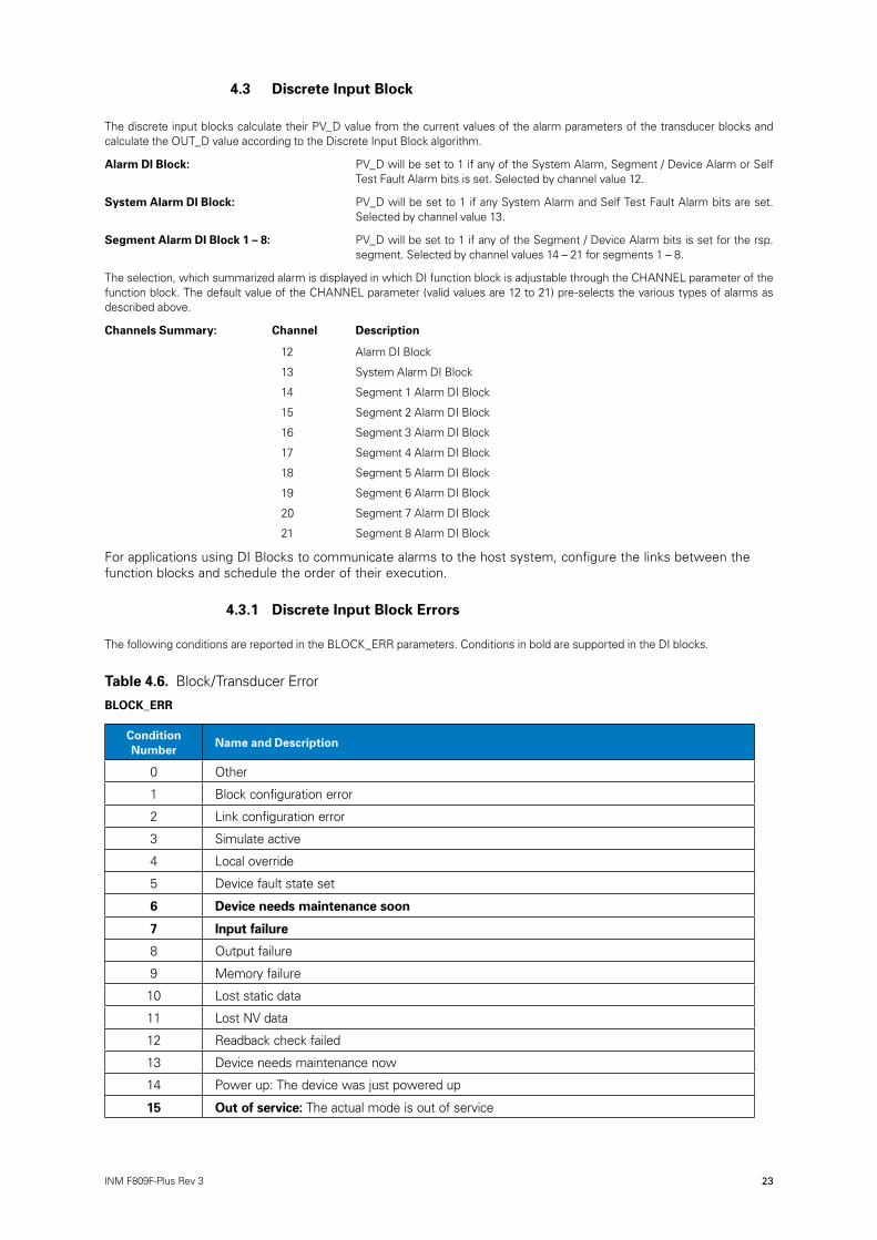
4.3 Discrete Input Block
The discrete input blocks calculate their PV_D value from the current values of the alarm parameters of the transducer blocks and calculate the OUT_D value according to the Discrete Input Block algorithm.
Alarm DI Block: PV_D will be set to 1 if any of the System Alarm, Segment / Device Alarm or Self Test Fault Alarm bits is set. Selected by channel value 12.
System Alarm DI Block: PV_D will be set to 1 if any System Alarm and Self Test Fault Alarm bits are set. Selected by channel value 13.
Segment Alarm DI Block 1 – 8: PV_D will be set to 1 if any of the Segment / Device Alarm bits is set for the rsp. segment. Selected by channel values 14 – 21 for segments 1 – 8.
The selection, which summarized alarm is displayed in which DI function block is adjustable through the CHANNEL parameter of the function block. The default value of the CHANNEL parameter (valid values are 12 to 21) pre-selects the various types of alarms as described above.
Channels Summary: Channel Description
12 Alarm DI Block
13 System Alarm DI Block
14 Segment 1 Alarm DI Block
15 Segment 2 Alarm DI Block
16 Segment 3 Alarm DI Block
17 Segment 4 Alarm DI Block
18 Segment 5 Alarm DI Block
19 Segment 6 Alarm DI Block
20 Segment 7 Alarm DI Block
21 Segment 8 Alarm DI Block
For applications using DI Blocks to communicate alarms to the host system, configure the links between the function blocks and schedule the order of their execution.
4.3.1 Discrete Input Block Errors
The following conditions are reported in the BLOCK_ERR parameters. Conditions in bold are supported in the DI blocks.
Table 4.6. Block/Transducer Error
BLOCK_ERR
Condition Number
Name and Description
0 Other
1 Block configuration error
2 Link configuration error
3 Simulate active
4 Local override
5 Device fault state set
6 Device needs maintenance soon
7 Input failure
8 Output failure
9 Memory failure
10 Lost static data
11 Lost NV data
12 Readback check failed
13 Device needs maintenance now
14 Power up: The device was just powered up
15 Out of service: The actual mode is out of service

24 INM F809F-Plus Rev 3
DRAFT - 02 March 2017
5 OPERATION AND MAINTENANCE
5.1 LED indicators Power status (green)
ON power on
OFF power off/fail
Segment status (amber)
ON segment monitored
OFF segment not monitored
FLASHING active segment alarm
5.2 FoundationtM fieldbus Information
FOUNDATIONTM fieldbus is an all-digital, serial, two-way, multidrop communication protocol that interconnects devices such as transmitters and valve controllers. It is a local area network (LAN) for instruments that enables basic control and I/O to be moved to the field devices. The model F809F-Plus uses FOUNDATIONTM fieldbus technology developed and supported by Eaton and the other members of the independent Fieldbus FOUNDATIONTM.
5.2.1 Commissioning (Addressing)
To be able to setup, configure, and have it communicate with other devices on a segment, a device must be assigned a permanent address. Unless requested otherwise, it is assigned a temporary address when shipped from the factory.
If there are two or more devices on a segment with the same address, the first device to start up will use the assigned address (ex. Address 20). Each of the other devices will be given one of the four available temporary addresses. If a temporary address is not available, the device will be unavailable until a temporary address becomes available.
Use the host system documentation to commission a device and assign a permanent address.
5.3 Hardware Maintenance The F809F-Plus has no moving parts and requires a minimal amount of scheduled maintenance. If a malfunction is suspected, check for an external cause before performing the diagnostics presented below.
5.3.1 Communication/Power Check If the Fieldbus Diagnostic Module does not communicate, or provides an erratic output, check for adequate voltage to it. The F809F-Plus requires between 9.0 and 32.0V DC on the communicating fieldbus segment. This is selected as Segment 1 or 8 of the monitored segment or a separate fieldbus segment. Check for wire shorts, open circuits, and multiple grounds on the communicating fieldbus segment.
5.3.2 Resetting the Configuration (RESTART) The Restart Processor parameter in the Resource Block offers the choice of:
a) an uninitialised restart that restarts the processor with the current configuration, or
b) a default restart that restores the default configuration. Note: Following a default restart the block is in OOS Mode. The block must be manually placed back into Auto Mode.
a) Restart resource, is accepted, but no function executed.
b) Run is the normal state for the block. To clear field after a Processor restart the parameter should be manually set to Run with some systems.
c) Restart processor will trigger an immediate reset of the processor. As the F809F-Plus does not acknowledge the request this may cause an error message with some systems.

25INM F809F-Plus Rev 3
DRAFT - 02 March 2017 DRAFT - 02 March 2017
5.4 Troubleshooting
5.4.1 FOUNDATIONTM fieldbus
Symptom Possible Cause Corrective Action
Device does not show up in the live list
Device that is acting as aLAS does not send out CD
All devices go off live list and then return
Network configuration parameters are incorrect
Network address is not in polled range. Power to the device is below the 9 VDC minimum.
Noise on the power / communication is too high.
LAS Scheduler was not downloaded to the Backup LAS device
Live list must be reconstructedby Backup LAS device
Set the network parameters of the LAS (host system) according to the FF Communications Profile:ST: 8MRD: 10DLPDU PhLO: 4MID: 7TSC: 4 (1 ms)T1: 1920000 (60 s)T2: 5760000 (180 s)T3: 480000 (15 s)
Set first Unpolled Node and Number of UnPolled Nodes so that the device address is within range.Increase the voltage to at least 9V.
Verify terminators and power conditioners are within specification Verify that the shield is properly terminated and not grounded at both ends. It is best to ground the shield at the power conditioner.
Ensure that all of the devices that are intended to be a Backup LAS are marked to receive the LAS schedule
Current link setting and configured links settings are different. Set the current link setting equal to the configured settings.
5.4.2 Resource Block
Symptom Possible Cause Corrective Action
Mode will not leave OOS
Block Alarms Will not work
Target mode not set
Memory Failure
Features
Notification
Set target mode to something other than OOS.
BLOCK_ERR will show the lost NV Data or Lost Static Data bit set.Restart the device by setting RESTART to Processor. If the block error does not clear, call the factory.
FEATURES_SEL does not have Alerts enabled. Enable the report bit. LIM_NOTIFY is not high enough. Set equal to MAX_NOTIFY.
5.4.3 System and Segment Transducer Block Troubleshooting
Symptom Possible Cause Corrective Action
Mode will not leave OOS Target mode not set
Resource block
Set target mode to AUTO
The actual mode of the Resource block is in OOS therefore set target mode to AUTO.

26 INM F809F-Plus Rev 3
DRAFT - 02 March 2017
Appendix A: Troubleshooting Table
Symptom Possible Causes
High peak or average noise Water/condensation in wiring, improperly connected shield, bad fieldbus device, bad physical layer component (power supply, terminator, wiring block), segment is not isolated from ground, fieldbus cable is located near noise producing cable, loose wire termination.
Recommendations: Inspect the network cable and connections. Tighten screw terminals and connector hold-down screws. Look for waterlogged cables, condensation in junction boxes, loose wires, FF cable routed near other signaling cables or AC power cables, loose strands of wire shorting to other wires/conductive objects. Check if fieldbus to shield short is present and if so follow recommendations below. Verify the segment is powered by an isolated fieldbus power supply or that the bulk supply for the fieldbus power supply is isolated and only powers one segment. Take noise measurements at multiple locations on the network to identify where noise is highest and most likely located. Measure resistance from shield to ground with a DMM and verify it is <100 . Disconnect devices one at a time to see if noise disappears. Replace terminators, fieldbus power supplies, and wiring blocks.
Symptom Possible Causes
Excessive retransmissions rate (on one device)
Bad spur wiring connection to device, not enough power to the device, bad device, bad port on the wiring block, noise on the spur.
Recommendations: Check if high noise levels are present and if so follow recommendations above. If the wiring block has a current limiting (SpurGuard™) feature, check the associated LED to make sure it isn’t constantly or intermittently lit. Inspect the wiring and connections from the wiring block to the device looking for waterlogged cables, condensation in junc-tion boxes, loose wires, FF cable routed near other signaling cables or AC power cables, loose strands of wire shorting to other wires/conductive objects. Try putting the device on a different spur from the wiring block. Replace the device.
Symptom Possible Causes
Excessive retransmissions rate (on all or multiple devices)
Wiring problem, not enough power to the devices, bad physical layer device (power supply, terminator, wiring block), noise on the bus
Recommendations: Determine if the entire network is affected or just part of it. Focus on the part of the network with problems. Check if high noise levels are present and if so follow recommendations above. Use the FBT-3/6 to check for high noise levels at the device and check the bus voltage is >9VDC at the device furthest from the power supply. Inspect the network looking for waterlogged cables, condensation in junction boxes, loose wires, FF cable routed near other signaling cables or AC power cables, loose strands of wire shorting to other wires/conductive objects. Replace the terminators, power supply/conditioner.
Symptom Possible Causes
Low device signal level (one device)
Bad spur wiring connection to device, not enough power to the device, bad device, bad port on
Recommendations: Use FBT-3/6 to check the voltage at the device is >9VDC. If the wiring block has a current limiting (SpurGuard™) feature, check the associated LED to make sure it isn’t constantly or intermittently triggered. Inspect the wiring and connections from the wiring block to the device looking for waterlogged cable, condensation, loose wires, loose strands of wire shorting to other wires/ conductive objects. Verify the maximum length of cable between any 2 devices does not exceed 1900m and spur length does not exceed 120m. Try connecting the device on a different spur from the wiring block. Replace the device.
Symptom Possible Causes
Low device signal level (all devices)
Wiring problem, not enough power to the devices, bad physical layer device (power supply, terminator, wiring block)
Recommendations: Use FBT 3/6 to check the voltage at the device furthest from it is >9VDC. Check the power LEDs on the wiring blocks are steadily lit. Inspect the wiring and connections (especially at the parts common to all devices such as power supply/conditioner, terminators, trunk cable, etc.) looking for waterlogged cable, condensation, loose wires, loose strands of wire shorting to other wires / conductive objects. Replace suspect physical layer components (power supply/conditioner, terminators, wiring blocks).
continued

27INM F809F-Plus Rev 3
DRAFT - 02 March 2017 DRAFT - 02 March 2017
Symptom Possible Causes
High device signal level (one device)
Bad device
Recommendations: Replace the device.
Symptom Possible Causes
High device signal level (all devices)
Missing terminator, failed terminator, improperly connected terminator, failed fieldbus power supply
Recommendations: Verify two terminators are installed (note that some terminators are built-in to power supplies/conditioners and wiring blocks, some are turned on/off with a switch and some are automatic). Check wiring to the terminators. Replace suspect terminators or the products that contain them. Replace the fieldbus power supply.
Symptom Possible Causes
Shield short to fieldbus Wiring problem, un-isolated device connected to the fieldbus, water in a cable/device/wiring block
Recommendations: Check for damaged cable, make sure all devices are properly connected. Verify that fieldbus is not connected to a ground at the power supply or to a device case. Look for shield connections to the fieldbus cable including stray strands of wire at wire terminations or un-insulated shield wire loose at the device. Disconnect portions of cable and check if the short goes away. Verify the fieldbus power supply is isolated from ground.
Symptom Possible Causes
Device is not “seen” on the bus/not communicating
Bad spur wiring connection to device, not enough power to the device, bad device, bad port on the wiring block
Recommendations: Check DC voltage at the device is >9VDC. If the wiring block the device is connected to has a current limiting (SpurGuard™) feature, check the associated LED to make sure it isn’t constantly or intermittently triggered. Inspect the wiring and connections from the wiring block to the device looking for waterlogged cable, condensation, loose wires, loose strands of wire shorting to other wires/conductive objects. Try putting the device on a different spur from the wiring block. Replace the device.

28 INM F809F-Plus Rev 3
DRAFT - 02 March 2017
this page is left intentionally blank

29INM F809F-Plus Rev 3
DRAFT - 02 March 2017 DRAFT - 02 March 2017
this page is left intentionally blank

DRAFT - 27 November 2014DRAFT - 02 March 2017
AUSTRALIAMTL Instruments Pty Ltd, 10 Kent Road, Mascot, New South Wales, 2020, Australia
Tel: +61 1300 308 374 Fax: +61 1300 308 463E-mail: [email protected]
BeNeLuxMTL Instruments BVAmbacht 6, 5301 KW ZaltbommelThe Netherlands
Tel: +31 (0) 418 570290 Fax: +31 (0) 418 541044E-mail: [email protected]
CHINACooper Electric (Shanghai) Co. Ltd955 Shengli Road, Heqing Industrial ParkPudong New Area, Shanghai 201201
Tel: +86 21 2899 3817 Fax: +86 21 2899 3992E-mail: [email protected]
FRANCEMTL Instruments sarl,7 rue des Rosiéristes, 69410 Champagne au Mont d’OrFrance
Tel: +33 (0)4 37 46 16 53 Fax: +33 (0)4 37 46 17 20E-mail: [email protected]
GERMANYMTL Instruments GmbH, Heinrich-Hertz-Str. 12, 50170 Kerpen, Germany
Tel: +49 (0)22 73 98 12 - 0 Fax: +49 (0)22 73 98 12 - 2 00E-mail: [email protected]
INDIAMTL India, No.36, Nehru Street, Off Old Mahabalipuram RoadSholinganallur, Chennai - 600 119, India
Tel: +91 (0) 44 24501660 /24501857 Fax: +91 (0) 44 24501463E-mail: [email protected]
ITALYMTL Italia srl, Via San Bovio, 3, 20090 Segrate, Milano, Italy
Tel: +39 02 959501 Fax: +39 02 95950759E-mail: [email protected]
JAPANCooper Crouse-Hinds Japan KK, MT Building 3F, 2-7-5 Shiba Daimon, Minato-ku,Tokyo, Japan 105-0012
Tel: +81 (0)3 6430 3128 Fax: +81 (0)3 6430 3129E-mail: [email protected]
NORWAYNorex ASFekjan 7c, Postboks 147, N-1378 Nesbru, Norway
Tel: +47 66 77 43 80 Fax: +47 66 84 55 33E-mail: [email protected]
RUSSIACooper Industries Russia LLCElektrozavodskaya Str 33Building 4Moscow 107076, Russia
Tel: +7 (495) 981 3770 Fax: +7 (495) 981 3771E-mail: [email protected]
SINGAPORECooper Crouse-Hinds Pte LtdNo 2 Serangoon North Avenue 5, #06-01 Fu Yu BuildingSingapore 554911
Tel: +65 6645 9864 / 6645 9865 Fax: +65 6 645 9865E-mail: [email protected]
SOUTH KOREACooper Crouse-Hinds Korea7F. Parkland Building 237-11 Nonhyun-dong Gangnam-gu,Seoul 135-546, South Korea.
Tel: +82 6380 4805 Fax: +82 6380 4839E-mail: [email protected]
UNITED ARAB EMIRATESCooper Industries/Eaton Corporation Office 205/206, 2nd Floor SJ Towers, off. Old Airport Road, Abu Dhabi, United Arab Emirates
Tel: +971 2 44 66 840 Fax: +971 2 44 66 841E-mail: [email protected]
UNITED KINGDOMEaton Electric Limited, Great Marlings, Butterfield, LutonBeds LU2 8DL
Tel: +44 (0)1582 723633 Fax: +44 (0)1582 422283E-mail: [email protected]
AMERICASCooper Crouse-Hinds MTL Inc. 3413 N. Sam Houston Parkway W.Suite 200, Houston TX 77086, USA
Tel: +1 281-571-8065 Fax: +1 281-571-8069E-mail: [email protected]
The given data is only intended as a product description and should not be regarded as a legal warranty of properties or guarantee. In the interest of further technical developments, we reserve the right to make design changes.
EUROPE (EMEA): +44 (0)1582 723633 [email protected]
THE AMERICAS: +1 800 835 7075 [email protected]
ASIA-PACIFIC: +65 6645 9864 / 9865 [email protected]
Eaton Electric Limited, Great Marlings, Butterfield, LutonBeds, LU2 8DL, UK.Tel: + 44 (0)1582 723633 Fax: + 44 (0)1582 422283E-mail: [email protected] © 2017 Eaton All Rights ReservedPublication No. INM F809F-Plus Rev 3 020317March 2017


![Profibus PA Fieldbus Display [ Revision 2 ] and Fieldbus ... Instruments... · Profibus PA Fieldbus Display [ Revision 2 ] and Fieldbus Indicator Fieldbus Interface Guide. ... Siemens](https://static.documents.pub/doc/80x56/5b2fe38e7f8b9ae16e8da83d/profibus-pa-fieldbus-display-revision-2-and-fieldbus-instruments.jpg)


