32
1 Instruction Manual Pneumatic Power

1
Instruction Manual Pneumatic Power

2
Table of Contents
Series 7000 Large Power Pneumatic Instrument System
Introduction and General Warnings . . . . . . . . . . . . . . . . . . . . . . . . . . . . . . . . . . . . . . . . . . . . . . . . . . . . . . . . . . . . . . . . . . . . 3
Markings . . . . . . . . . . . . . . . . . . . . . . . . . . . . . . . . . . . . . . . . . . . . . . . . . . . . . . . . . . . . . . . . . . . . . . . . . . . . . . . . . . . . . . . . . . . . . . 4
Standards & Environmental Parameters . . . . . . . . . . . . . . . . . . . . . . . . . . . . . . . . . . . . . . . . . . . . . . . . . . . . . . . . . . . . . . . . 4
REF 7105-XXX Drill Reamer Handpiece . . . . . . . . . . . . . . . . . . . . . . . . . . . . . . . . . . . . . . . . . . . . . . . . . . . . . . . . . . . . . . . 5-8
REF 7205-XXX Oscillating Saw . . . . . . . . . . . . . . . . . . . . . . . . . . . . . . . . . . . . . . . . . . . . . . . . . . . . . . . . . . . . . . . . . . . . . . . 8-11
REF 7405-XXX Reciprocating Saw . . . . . . . . . . . . . . . . . . . . . . . . . . . . . . . . . . . . . . . . . . . . . . . . . . . . . . . . . . . . . . . . . .12-15
Drive Couplers . . . . . . . . . . . . . . . . . . . . . . . . . . . . . . . . . . . . . . . . . . . . . . . . . . . . . . . . . . . . . . . . . . . . . . . . . . . . . . . . . . . .16-24
Cleaning and Sterilization Instructions . . . . . . . . . . . . . . . . . . . . . . . . . . . . . . . . . . . . . . . . . . . . . . . . . . . . . . . . . . . . .25-28
Troubleshooting . . . . . . . . . . . . . . . . . . . . . . . . . . . . . . . . . . . . . . . . . . . . . . . . . . . . . . . . . . . . . . . . . . . . . . . . . . . . . . . . . . . . . . 29
Warranty, Service & Repair . . . . . . . . . . . . . . . . . . . . . . . . . . . . . . . . . . . . . . . . . . . . . . . . . . . . . . . . . . . . . . . . . . . . . . . . .30-31
3
Introduction This manual has been written to help describe the procedures required to keep the MicroAire Series 7000 Pneumatic Large Power System with Handpiece Models: REF 7105-XXX, REF 7205-XXX, and REF 7405-XXX operating properly .
Throughout the manual, the following terms are used to identify tips and precautions that will help avoid accidental injury to patients or personnel, or prevent damage to the system .
NOTE: Used to point out the easiest means of carrying out techniques .
WARNING: Used to indicate that the safety of the patient and hospital personnel could be involved .
CAUTION: Used to point out special procedures or precautions that must be followed to avoid damaging the system/instruments .
General Warnings:
CAUTION: The Series 7000 pneumatic handpieces are powered by standard hospital compressed nitrogen or dried and filtered compressed air (99 .7% pure) .
CAUTION: It is essential to dry and filter compressed air as the air lines frequently contain oil vapor, moisture, and bacteria .
CAUTION: Federal law (USA) restricts this device to sale by or on the order of a physician (or properly licensed practitioner) .
WARNING: Prior to use, all system components (handpiece, couplers, and air hose) should be inspected to detect any damage or malfunction . DO NOT use any component if damage is apparent .
WARNING: Prior to use, all system component manuals should be reviewed for important warnings and instructions for use .
WARNING: Eye protection must be worn when operating any power equipment . Dislodged burs, blades, or bone fragments can result in eye injury, blindness, or contamination of the eye from patient tissue or body fluids .
NOTE: All personnel should become familiar with the power equipment before it is set-up for use in any procedure . Personnel trained should include, but not be limited to, central processing personnel, members of the surgical team, and the bioengineering department .

4
Markings:
Attention, see instructions for use . This unit is designed for Short-Time Operation (2 Minutes Maximum ON Time . Allow to cool before Re-Use .)
Forward Direction: Rotation will be counterclockwise when viewed from the front of the instrument .
Reverse Direction: Rotation will be when clockwise when viewed from the front of the instrument
Neutral Position: Position when forward/reverse control is in the middle . Output shaft will NOT turn . Motor will run .
DO NOT lubricate
DO NOT immerse
Lock
Unlock
0086
European Conformity mark with MicroAire notified body number
REF Product catalog number
SN Serial number
Environmental Parameters:
OPERATING and STORAGE CONDITIONSThe devices in this manual have been tested and proven to operate after repeated exposure within/to the following conditions:
Operation Storage and Transportation
Temperature 50°F (10°C) 104°F (40°C)0°F (-20°C) 120°F (49°C)
Relative Humidity Limits 0% 91%
0% 91%
Atmospheric Pressure Limits 86 106
86 106
Shipping: The materials and components used in the construction of this device were selected to ensure that the device could be shipped by any standard commercial method without special handling conditions .

5
REF 7105-XXX Drill Reamer Handpiece
Features and Descriptions1 . Coupler Locking Ring – The coupler locking
ring locks and releases a drive coupler on the REF 7105-XXX Drill Reamer . The Coupler Locking Ring must be pulled back completely to fully insert or remove a drive coupler into the REF 7105 Drill Reamer .
2 . Trigger / Safety Lock – The MicroAire REF 7105-XXX Drill Reamer handpiece operates at variable speeds and is controlled by depressing the trigger . The instrument is in the “OFF” position when the trigger is not depressed . As the trigger is depressed fully, the speed increases slowly from 0% - 100% . The trigger also serves as the safety lock for the handpiece by rotating to the right or left .
3 . Forward/Reverse/Neutral Control Switch– The Drill Reamer will operate in forward and reverse; clockwise and counterclockwise rotation . The direction control is located on the back of the handpiece and is operated by moving the forward/reverse control from right to left . To select the forward direction, move the control switch to the position all the way to the right . To select the reverse direction, move the control switch to the position all the way to the left . The Drill Reamer has a neutral position when the forward/reverse control is in the middle . The motor will run, but the output shaft will not turn .
4 . Air Hose Connector - The MicroAire REF 7105-XXX Drill Reamer handpiece is available with a choice of air hose connectors . Hall®, 3M Maxi®, Stryker®, or Synthes® .
3 1
2
4

Handpiece Safety Mechanisms:
Trigger in upright – “ON” position Trigger in turned – “OFF” position(Trigger can be turned in either the right or left direction from the upright “ON” position to be turned “OFF” .)
Technical Data – Specifications*
High Torque Output: 0 – 250 rpm, 0-150 in/lbs (16 .9 N-m)
High Speed Output: 0 – 750 rpm, 0 – 50 in/lbs . (5 .6 N-m)
Cannulation: 5 .0 mm ( .200”)
Handpiece Weight: 1 .9lbs (879g)
*Values are typical and may vary
REF 7105-XXX Drill Reamer Handpiece
The MicroAire REF 7105-XXX Drill Reamer is a single-trigger, two-speed, multi-purpose (drill, ream, pin drive) handpiece with a selection of quick-connect Drive Couplers . The couplers automatically key to the correct drive speed (250 rpm or 750 rpm) . The individual drive couplers are designed to accept standard orthopaedic instrument fittings including Jacobs®, Zimmer ®(Also referred to as Hudson® Modified Trinkle), Hudson®, Aesculap®, Synthes®, and Trinkle® . Adjustable wire and pin driver couplers allow for easy insertion of smooth or threaded wires and pins from 1 .6 mm – 4 .0mm ( .062” – 5/32”) .
All personnel should become familiar with the power equipment before it is set-up for use in any surgical procedure . Personnel to be in-serviced should include, but not be limited to, central processing personnel, members of the surgical team, and the bio-engineering departments .
6

Drill Reamer Setup:
WARNING: To prevent inadvertent running of the handpiece while loading a drive coupler or surgical accessory, do not attach the air hose until the coupler and surgical accessory have been loaded for use .
1 . Inspect the handpiece and couplers for damage, corrosion, or signs of excessive wear . WARNING: If any corrosion or debris is detected in/on the instrument, it must be considered contaminated . Replace the instrument immediately or remove it from the surgical field and reprocess . If the instrument looks damaged or shows signs of excessive wear, it should not be used .
2 . Make sure the handpiece trigger is set to the “OFF” position .3 . Check all surgical accessories . Make sure that reamers, drills, pins, etc .
are not dull or bent, and that they lock correctly into the handpiece .4 . Attach a large power Drive Coupler (REF 7100-XXX series) to the front
of the drill reamer handpiece . To connect a Drive Coupler to the REF 7105-XXX Drill Reamer Handpiece, pull back on the coupler locking ring and insert the drive coupler with a slight twisting motion as the coupler locks into position . Release the coupler locking ring to lock the coupler in place before use . The coupler locking ring must release completely and set flush with the base of the drive coupler .
5 . Insert the surgical accessory (drill, reamer, pin, etc .) into the drive coupler, checking for as secure and proper fit . Use blue and red color coding for easy coupler selection . Red banded couplers provide the high torque and slower speed preferred for reaming . Blue banded couplers provide less torque and higher speed preferred for drilling and pin driving .
a . Make sure that , when the trigger is in the “OFF” position, it prevents activation of the motor .b . Make sure that, when the trigger is in the “ON” position, it allows activation of the motor by depressing
the trigger .c . Make sure that the trigger does not stick in the fully depressed position . If it has any tendency to stick,
re-clean and re-sterilize the handpiece . If the handpiece still does not meet the above requirements, return the handpiece for service .
6 . Attach the appropriate MicroAire or other manufacturer’s air hose to handpiece . To attach the air hose to the handpiece, place the air hose connector inside the air hose connector on the bottom of the handpiece, push and twist to the right to secure in place . Before use, check to make sure the air hose is locked securely on the handpiece by giving the air hose a firm tug . The air hose should remain securely attached to the handpiece . If the air hose is lose or not secure, reinstall or replace with another air hose .
7 . Choose designated drive direction on back of handpiece . To select the forward direction, move the control switch to the position . To select the reverse direction, move the control switch to the position .
8 . With the surgical accessory inserted, test run the instrument in the sterile field for 3 short 5 – 10 seconds bursts, checking for any indications of irregular noise, or excessive heat or vibration . Irregular grinding noises may indicate incomplete drive coupler connection or impending failure or over heating of the handpiece . If any irregular grinding noises are present, check for proper setup or return the instrument for service .
9 . Drill Reamer is ready for use .
CAUTION:Check the trigger safety lock before operating the handpiece . If the trigger should stick in the depressed “ON” position, do not use the handpiece . Immediately disconnect the air hose from the handpeice and return the handpiece to the factory for service . Always use the trigger safety lock when the handpiece is not running .
Check the forward/reverse control . Make certain that the handpiece is fully in the forward position for drilling, pinning, and reaming . The handpiece should be fully in the forward position for backing out screws, taps or threaded Steinmann pins .
7

8
Make sure that the drive coupler and attachments are firmly locked in place by testing at low speed . When using a reaming attachment or driving a large pin, keep both hands on the handpiece and advance the trigger slowly to control the reactive torque .
When driving Steinmann pins, use caution to avoid the sharp point that may protrude from the rear cannulation of the instrument .
Air Pressure:Use the MicroAire REF 9500-000 or similar pressure regulator . The main tank pressure gauge should indicate a minimum of 500 psi (35kg/cm2) . Set the output pressure gauge to indicate 100 psi (7kg/cm2) with the handpiece running at full throttle .
If you have a wall or ceiling mounted air system and the air hose is longer than 3 meters, the air pressure must be increased by 6 psi (0 .4kg/cm2) for each additional meter of hose length . This may cause the gauge to indicate 125 to 150 psi (8 .75kg/cm2 - 10 .5kg/cm2) when the handpiece is not running . This is OK . If the handpiece runs slowly and lacks power, it is probably not getting adequate air pressure .
REF 7205-XXX Oscillating Saw Handpiece
2
1
3
4
5
9
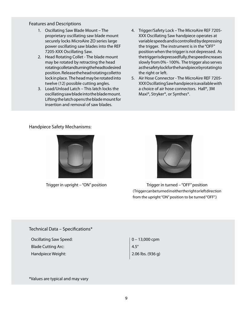
Features and Descriptions1 . Oscillating Saw Blade Mount – The
proprietary oscillating saw blade mount securely locks MicroAire ZO series large power oscillating saw blades into the REF 7205-XXX Oscillating Saw .
2 . Head Rotating Collet - The blade mount may be rotated by retracting the head rotating collet and turning the head to desired position . Release the head rotating collet to lock in place . The head may be rotated into twelve (12) possible cutting angles .
3 . Load/Unload Latch – This latch locks the oscillating saw blade into the blade mount . Lifting the latch opens the blade mount for insertion and removal of saw blades .
4 . Trigger/Safety Lock – The MicroAire REF 7205-XXX Oscillating Saw handpiece operates at variable speeds and is controlled by depressing the trigger . The instrument is in the “OFF” position when the trigger is not depressed . As the trigger is depressed fully, the speed increases slowly from 0% - 100% . The trigger also serves as the safety lock for the handpiece by rotating to the right or left .
5 . Air Hose Connector - The MicroAire REF 7205-XXX Oscillating Saw handpiece is available with a choice of air hose connectors . Hall®, 3M Maxi®, Stryker®, or Synthes® .
Handpiece Safety Mechanisms:
Trigger in upright – “ON” position Trigger in turned – “OFF” position(Trigger can be turned in either the right or left direction from the upright “ON” position to be turned “OFF” .)
Technical Data – Specifications*
Oscillating Saw Speed: 0 – 13,000 cpm
Blade Cutting Arc: 4 .5°
Handpiece Weight: 2 .06 lbs . (936 g)
*Values are typical and may vary

REF 7506 Oscillating Saw Handpiece
The MicroAire REF 7205-XXX Oscillating Saw is a single-trigger, variable speed, multi-purpose handpiece designed for total joint arthroplasty . The saws heavy-duty high speed oscillating mechanism is designed to drive the extra long and wide saw blades required for today’s total knee osteotomies . The oscillating saw may also be used in total hip arthroplasty, trauma, and revision sternotomies .
All personnel should become familiar with the power equipment before it is set-up for use in any surgical procedure . Personnel to be in-serviced should include, but not be limited to, central processing personnel, members of the surgical team, and the bio-engineering departments .
Oscillating Saw Setup:
WARNING: To prevent inadvertent running of the handpiece while loading a saw blade, do not attach the air hose until the saw blade has been securely locked into place and is ready for use .
1 . Inspect the handpiece for damage, corrosion, or signs of excessive wear .
WARNING: If any corrosion or debris is detected in/on the instrument, it must be considered contaminated . Replace the instrument immediately or remove it from the surgical field and reprocess . If the instrument looks damaged or shows signs of excessive wear, it should not be used .
2 . Make sure the handpiece trigger is set to the “OFF” position .3 . Check all surgical accessories . Make sure that saw blades are not dull or bent, and that they lock correctly into
the handpiece .4 . To load a saw blade, use ONLY MicroAire “ZO” series large oscillating saw
blades . Release the Load/Unload Latch by pulling down and away from the cutting head . The blade mount is spring loaded and will open to reveal blade alignment pins . Insert the blade so it sits flat against the back of the blade mount and the blade hub is seated over the alignment pins . Hold the saw blade securely in place and push up and back on the latch to lock the blade into place . To remove a saw blade from the saw, release the Load/Unload Latch and remove saw blade .
a . Make sure that, when the trigger is in the “OFF” position, it prevents activation of the motor .
b . Make sure that, when the trigger is in the “ON” position, it allows activation of the motor by depressing the trigger .
c . Make sure that the trigger does not stick in the fully depressed position . If it has any tendency to stick, re-clean and re-sterilize the handpiece . If the handpiece still does not meet the above requirements, return the handpiece for service .
5 . Attach the appropriate MicroAire or other manufacturer’s air hose to handpiece . To attach the air hose to the handpiece, place the air hose connector inside the air hose connector on the bottom of the handpiece, push and twist to the right to secure in place . Before use, check to make sure the air hose is locked securely on the handpiece by giving the air hose a firm tug . The air hose should remain securely attached to the handpiece . If the air hose is lose or not secure, reinstall or replace with another air hose .
6 . The oscillating saw head may be positioned in twelve (12) possible cutting angle positions . (30° increments) To rotate the oscillating saw head, pull back the head rotating collet and turn the saw head in either direction to the desired angle . Release the head rotating collet to lock the head in place .
10

WARNING: To prevent damage to the instrument, the oscillating saw head must be firmly locked into place before use . The neck of the oscillating saw head must be seated flush with the head locking collet to ensure that it is properly locked in position .
7 . With the saw blade securely locked in place, test run the instrument in the sterile field for 3 short 5 – 10 seconds bursts, checking for any indications of irregular noise, or excessive heat or vibration . If any irregular grinding noises are present, check for proper setup or return the instrument for service .
8 . Check for excessive heat .
WARNING: Excessive heat is the most likely cause of patient injury . Any power instrument is subject to overheating, especially in the nose section . Even normal operation of the system in a cycle other than 2 minutes “ON” and allowing the handpiece to cool to room temperature may cause the handpiece to become hot .
To check for overheating, test run the handpiece for approximately 30 seconds . Periodically monitor the temperature of the nose section . The temperature should not rise above 115°F (46°C) and should not become uncomfortable to touch with gloved fingers . If the instrument temperature exceeds 115°F (46°C), please return for service .
The following conditions may cause overheating or total failure of the instrument:
Surgical usage, cleaning, and sterilization can be destructive to instruments for several reasons:• Blood deposits, saline, and bone fragments often enter the forward section of the handpiece during
operation . Saline causes corrosion, and blood produces restrictive deposits .• Repeated sterilization removes grease from the bearings, and leaves mineral deposits on moving parts .
Regular maintenance is recommended to replace lubrication, bearings, seals, and o-rings .• The force of high torque and high speed commonly encountered in many surgical procedures produces
wear on bearings and gear train mechanisms .
WARNING: Do not use excessive force or pry on the saw blade when in use . Doing so may cause the blade to bend or break, causing potential patient injury .
CAUTION: Allow the saw blade to do the cutting when operating the saw . Applying too much pressure may bend the blade and reduce the cutting quality .
9 . Oscillating saw is ready for use .
Air Pressure:Use the MicroAire REF 9500-000 or similar pressure regulator . The main tank pressure gauge should indicate a minimum of 500 psi (35kg/cm2) . Set the output pressure gauge to indicate 100 psi (7kg/cm2) with the handpiece running at full throttle .
If you have a wall or ceiling mounted air system and the air hose is longer than 3 meters, the air pressure must be increased by 6 psi (0 .4kg/cm2) for each additional meter of hose length . This may cause the gauge to indicate 125 to 150 psi (8 .75kg/cm2 - 10 .5kg/cm2) when the handpiece is not running . This is OK . If the handpiece runs slowly and lacks power, it is probably not getting adequate air pressure .
11

12
REF 7405-XXX Reciprocating Saw Handpiece
Features and Descriptions1 . Blade Mount – Grippers that hold and align
reciprocating saw blades in the reciprocating saw . The blade mount with blade may be oriented in any 360° position .
2 . Blade Locking Collar – The locking collar rotates to securely lock the saw blade in the saw .
3 . Trigger/Safety Lock – The MicroAire REF 7405-XXX Reciprocating Saw handpiece operates at variable speeds and is controlled by depressing the trigger . The instrument is in the “OFF” position when the trigger is not depressed . As the trigger is depressed fully, the speed increases slowly from 0% - 100% . The trigger also serves as the safety lock for the handpiece by rotating to the right or left .
4 . Air Hose Connector - The MicroAire REF 7405-XXX Reciprocating Saw handpiece is available with a choice of air hose connectors . Hall®, 3M Maxi®, Stryker®, or Synthes® .
1
2
3
4

13
Handpiece Safety Mechanisms:
Trigger in upright – “ON” position Trigger in turned – “OFF” position(Trigger can be turned in either the right or left direction from the upright “ON” position to be turned “OFF” .)
Technical Data – Specifications*
Reciprocating Saw Speed: 0 – 14,000 cpm
Blade Cutting Stroke: 3 .2 mm ( .125”)
Handpiece Weight: 1 .75 lbs . (794 g)
*Values are typical and may vary

REF 7405-XXX Reciprocating Saw Handpiece
The MicroAire REF 7405-XXX Reciprocating Saw handpiece is a single-trigger, variable speed, multi-purpose handpiece designed for linear bone cutting in total joint arthroplasy and other large bone orthopaedic procedures .
All personnel should become familiar with the power equipment before it is set-up for use in any surgical procedure . Personnel to be in-serviced should include, but not be limited to, central processing personnel, members of the surgical team, and the bio-engineering departments .
Reciprocating Saw Setup:
WARNING: To prevent inadvertent running of the handpiece while loading a saw blade, do not attach the air hose until the saw blade has been securely locked into place and is ready for use .
1 . Inspect the handpiece for damage, corrosion, or signs of excessive wear .
WARNING: If any corrosion or debris is detected in/on the instrument, it must be considered contaminated . Replace the instrument immediately or remove it from the surgical field and reprocess . If the instrument looks damaged or shows signs of excessive wear, it should not be used .
2 . Make sure the handpiece trigger is set to the “OFF” position .3 . Check all surgical accessories . Make sure that saw blades are not dull or bent, and that they lock correctly into
the handpiece .4 . To load a saw blade, use MicroAire “ZR” series large reciprocating saw blades . Rotate the locking collar in the
counterclockwise direction to open the blade mount . Insert the saw blade in-between the blade mount grippers and push the blade back into the saw hub until it stops and is fully seated . Tighten the blade by rotating the blade locking collar in the clockwise direction until it is hand tight and will no longer turn . Hold the blade in place while tightening the blade locking collar to prevent the saw blade from rotating . To remove the saw blade, follow the above steps in reverse .
a . Make sure that, when the trigger is in the “OFF” position, it prevents activation of the motor .b . Make sure that, when the trigger is in the “ON” position, it allows activation of the motor by depressing
the trigger .c . Make sure that the trigger does not stick in the fully depressed position . If it has any tendency to stick,
re-clean and re-sterilize the handpiece . If the handpiece still does not meet the above requirements, return the handpiece for service .
5 . Attach the appropriate MicroAire or other manufacturer’s air hose to handpiece . To attach the air hose to the handpiece, place the air hose connector inside the air hose connector on the bottom of the handpiece, push and twist to the right to secure in place . Before use, check to make sure the air hose is locked securely on the handpiece by giving the air hose a firm tug . The air hose should remain securely attached to the handpiece . If the air hose is lose or not secure, reinstall or replace with another air hose .
6 . With the saw blade securely locked in place, test run the instrument in the sterile field for 3 short 5 – 10 seconds bursts, checking for any indications of irregular noise, or excessive heat or vibration . Irregular grinding noises may indicate impending failure or over heating of the handpiece . If any irregular grinding noises are present, check for proper setup or return the instrument for service .
7 . Check for excessive heat .
WARNING: Excessive heat is the most likely cause of patient injury . Any power instrument is subject to 14

15
overheating, especially in the nose section . Even normal operation of the system in a cycle other than 2 minutes “ON” and allowing the handpiece to cool to room temperature may cause the handpiece to become hot .
To check for overheating, test run the handpiece for approximately 30 seconds . Periodically monitor the temperature of the nose section . The temperature should not rise above 115°F (46°C) and should not become uncomfortable to touch with gloved fingers . If the instrument temperature exceeds 115°F (46°C), please return for service .
The following conditions may cause overheating or total failure of the instrument:
Surgical usage, cleaning, and sterilization can be destructive to instruments for several reasons:• Blood deposits, saline, and bone fragments often enter the forward section of the handpiece during
operation . Saline causes corrosion, and blood produces restrictive deposits .• Repeated sterilization removes grease from the bearings, and leaves mineral deposits on moving parts .
Regular maintenance is recommended to replace lubrication, bearings, seals, and o-rings .• The force of high torque and high speed commonly encountered in many surgical procedures produces
wear on bearings and gear train mechanisms .
WARNING: Large reciprocating saw blades are longer in length and can whip when the handpiece is operated below the maximum speed . Personnel should be alert . Blade whip can increase the chance of blade fracture and user/patient injury .
WARNING: Do not use excessive force or pry on the saw blade when in use . Doing so may cause the blade to bend or break, causing potential patient injury .
CAUTION: Allow the saw blade to do the cutting when operating the saw . Applying too much pressure may bend the blade and reduce the cutting quality .
8 . Reciprocating saw is ready for use .
Air Pressure:Use the MicroAire REF 9500-000 or similar pressure regulator . The main tank pressure gauge should indicate a minimum of 500 psi (35kg/cm2) . Set the output pressure gauge to indicate 100 psi (7kg/cm2) with the handpiece running at full throttle .
If you have a wall or ceiling mounted air system and the air hose is longer than 3 meters, the air pressure must be increased by 6 psi (0 .4kg/cm2) for each additional meter of hose length . This may cause the gauge to indicate 125 to 150 psi (8 .75kg/cm2 - 10 .5kg/cm2) when the handpiece is not running . This is OK . If the handpiece runs slowly
and lacks power, it is probably not getting adequate air pressure .

16
Drive Couplers (For use with REF 7105-XXX Drill Reamer Handpiece)
The MicroAire Series 7000 REF 7105-XXX Drill Reamer handpiece operates using a selection of quick-connect drive couplers . The couplers automatically key to the correct drive speed (250 rpm or 750 rpm) . The individual drive couplers are designed to accept standard orthopaedic instrument fittings including Jacobs, Zimmer ®(Also referred to as Hudson® Modified Trinkle), Hudson®, Aesculap®, Synthes®, and Trinkle® . Adjustable wire and pin driver couplers allow for easy insertion of smooth or threaded wires and pins from 1 .6 mm – 4 .0mm ( .062” – 5/32”) .
How to connect drive couplers and wire/pin drivers
Attach a large power Drive Coupler (REF 7100/7505-XXX) to the front of the drill reamer handpiece . To connect a Drive Coupler to the REF 7105-XXX Drill Reamer Handpiece, pull back on the coupler locking ring and insert the drive coupler with a slight twisting motion as the coupler locks into position . Release the coupler locking ring to lock the coupler in place before use . The coupler locking ring must release completely and set flush with the base of the drive coupler .
Drill/Screwdriver Drive Couplers (750 rpm) Blue ID Band
REF 7100-002 Trinkle Drive Coupler – 750 rpm (nominal)
The Trinkle drive coupler accepts standard Trinkle shank twist drills and screw driver bits .
To insert a Trinkle accessory into the REF 7100-002 Trinkle drive coupler:1 . Make sure the handpiece trigger is set to the “OFF” position and the coupler is properly locked into the
handpiece .2 . Pull back on the drive coupler locking collar located on the nose end of the coupler .3 . Insert the Trinkle accessory, making sure that it seats and locks properly into the drive coupler .4 . Release the locking collar .5 . Being careful of sharp drill flutes, pull on the accessory to make sure it does not slip loose .

17
REF 7100-003 ¼” Jacobs® Drill Coupler (6 .35 mm) – 750 rpm (nominal) Requires REF 4100-030 ¼” Jacobs® Key (included)
This Jacobs® drill coupler accepts MicroAire 8051 and 8054 series Jacobs® style twist drills with diameters between 1 .0 mm ( .039”) and 6 .5 mm ( .25”) and smooth shank reamers .
To insert a twist drill into the REF 7100-003 ¼” Jacobs® drill coupler:1 . Make sure the handpiece trigger is set to the “OFF” position and the coupler is properly locked into the
handpiece .2 . Using the ¼” Jacobs® key (REF 4100-030), open the chuck to the desired size .3 . Insert the twist drill, making sure it seats properly in the coupler .4 . Tighten the Jacobs® chuck using the same Jacobs® key (REF 4100-030) .5 . Being careful of sharp drill flutes, pull on the drill bit to make sure it does not disengage .
REF 7100-004 ¼” Keyless Drill Coupler (6 .35 mm) – 750 rpm (nominal)
This keyless drill coupler accept MicroAire 8051 and 8054 series Jacobs® style twist drills with diameters between 1 .0 mm (0 .39”) and 6 .5mm ( .25”) and smooth shank reamers . Due to loosening potential, applications requiring high torque are not recommended while running in reverse with the keyless drive couplers .
To insert a twist drill into the REF 7100-004 ¼” keyless drill coupler:1 . Make sure the handpiece trigger is set to the “OFF” position and the coupler is properly locked into the
handpiece .2 . Open the ¼” keyless drive coupler to desired size by firmly holding the middle adjustment ring and twisting
the nose of the coupler counterclockwise .3 . Insert the twist drill, making sure it seats properly in the coupler .4 . Tighten the keyless coupler by firmly holding the middle adjustment ring and twisting the nose of the
coupler clockwise until it is finger tight and the twist drill is secure .5 . Being careful of sharp drill flutes, pull on the drill bit to make sure it does not disengage .

18
REF 7100-005 1/8” Keyless Drill Coupler (3 .2mm) – 750 rpm (nominal)
This keyless drill coupler accept MicroAire 8051 and 8054 series Jacobs® style twist drills with diameters between 1 .0 mm (0 .39”) and 3 .2 mm (1/8”) and smooth shank reamers . Due to loosening potential, applications requiring high torque are not recommended while running in reverse with the keyless drive couplers .
To insert a twist drill into the REF 7100-005 1/8” keyless drill coupler:1 . Make sure the handpiece trigger is set to the “OFF” position and the coupler is properly locked into the
handpiece .2 . Open the 1/8” keyless drive coupler to desired size by firmly holding the middle adjustment ring and
twisting the nose of the coupler counterclockwise .3 . Insert the twist drill, making sure it seats properly in the coupler .4 . Tighten the keyless coupler by firmly holding the middle adjustment ring and twisting the nose of the
coupler clockwise until it is finger tight and the twist drill is secure .5 . Being careful of sharp drill flutes, pull on the drill bit to make sure it does not disengage .
REF 7100-006 Synthes® Style Quick-Connect Drill Coupler – 750 rpm (nominal)
The Synthes® style drill coupler accepts MicroAire 8053-type twist drills and taps and other accessories with the Synthes® style drill fitting .
NOTE: The REF 7100-006 will not accept MicroAire twist drill numbers REF 8053-020, REF 8053-024, REF 8053-032, REF 8053-036, REF 8053-115, and REF 8053-119 .
To insert a twist drill into the REF 7100-006 Synthes® Style Quick-Connect Drill Coupler:1 . Make sure the handpiece trigger is set to the “OFF” position and the coupler is properly locked into the
handpiece .2 . Pull back on the locking collar located on the front of the coupler . (knurled section) 3 . Insert the twist drill making sure it seats fully in the coupler .4 . Release the locking collar on the coupler .5 . Being careful of sharp drill flutes, pull on the drill bit to make sure it does not disengage .

REF 7100-051 Zimmer® Drill Coupler – 750 rpm (nominal) (Commonly referred to as by other manufacturers)
The REF 7100-051 Zimmer® Drill coupler is designed to accept standard Zimmer® (Hudson® modified Trinkle) quick-connect drill/reamer attachments . The 750 rpm high speed drive coupler does not provide the high torque often required for reaming in total hip arthroplasty and is more appropriate for low torque reaming/drilling . (Total knee arthroplasty)
To insert a reamer or quick-connect adapter into the REF 7100-051 Zimmer® Drill Coupler:1 . Make sure the handpiece trigger is set to the “OFF” position and the coupler is properly locked into the
handpiece .2 . Pull back on the locking collar located on the front of the coupler . 3 . Insert the reamer/ drill making sure it seats fully in the coupler .4 . Release the locking collar on the coupler .5 . Being careful of sharp reamers or drill flutes, pull on the accessory to make sure it does not disengage .
REF 7100-058 Hudson® Drill Coupler – 750 rpm (nominal)
The REF 7100-058 Hudson® Drill coupler is designed to accept standard Hudson® quick-connect drill/reamer attachments . The 750 rpm high speed drive coupler does not provide the high torque often required for reaming in total hip arthroplasty and is more appropriate for low torque reaming/drilling . (Total knee arthroplasty)
To insert a reamer or quick-connect adapter into the REF 7100-058 Hudson® Drill Coupler:1 . Make sure the handpiece trigger is set to the “OFF” position and the coupler is properly locked into the
handpiece .2 . Pull back on the locking collar located on the front of the coupler . 3 . Insert the reamer/ drill making sure it seats fully in the coupler .4 . Release the locking collar on the coupler .5 . Being careful of sharp reamers or drill flutes, pull on the accessory to make sure it does not disengage .
19

20
Reaming Drive Couplers (250 rpm) Red ID Band
REF 7100-001 Zimmer® Reamer Coupler – 250 rpm (nominal)(Often referred to as Hudson® Modified Trinkle)
The REF 7100-001 Zimmer® Reamer Coupler (Hudson® Modified Trinkle) is designed to accept standard Zimmer® style quick-connect reamer attachments . The 250 rpm drive coupler has been designed to provide the high torque required for reaming in total hip arthroplasty .
To insert a reamer into the REF 7100-001 Zimmer® Reamer Coupler:1 . Make sure the handpiece trigger is set to the “OFF” position and the coupler is properly locked into the
handpiece .2 . Pull back on the locking collar located on the front of the coupler . 3 . Insert the reamer making sure it seats fully in the coupler .4 . Release the locking collar on the coupler .5 . Being careful of sharp reamers or drill flutes, pull on the accessory to make sure it does not disengage .
REF 7100-008 Hudson® Reamer Coupler – 250 rpm (nominal)
The REF 7100-008 Hudson® Reamer Coupler is designed to accept standard Hudson® style quick-connect reamer attachments . The 250 rpm drive coupler has been designed to provide the high torque required for reaming in total hip arthroplasty .
To insert a reamer into the REF 7100-008 Hudson® Reamer Coupler:1 . Make sure the handpiece trigger is set to the “OFF” position and the coupler is properly locked into the
handpiece .2 . Pull back on the locking collar located on the front of the coupler . 3 . Insert the reamer making sure it seats fully in the coupler .4 . Release the locking collar on the coupler .5 . Being careful of sharp reamers or drill flutes, pull on the accessory to make sure it does not disengage .

21
REF 7100-010 ¼” Jacobs® Reamer Coupler (6 .35 mm) – 250 rpm (nominal)
The REF 7100-010 ¼” Jacobs® Reamer Coupler is designed to accept smooth shank reamers and adapters that do not contain a quick-connect fitting . The couplers 250 rpm drive speed provides for maximum reaming torque .
To insert a reamer or twist drill into the REF 7100-010 ¼” Jacobs® reamer coupler:1 . Make sure the handpiece trigger is set to the “OFF” position and the coupler is properly locked into the
handpiece .2 . Using the ¼” Jacobs® key (REF 4100-030), open the chuck to the desired size .3 . Insert the twist drill, making sure it seats properly in the coupler .4 . Tighten the Jacobs® chuck using the same Jacobs® key (REF 4100-030) .5 . Being careful of sharp reamer and drill flutes, pull on the drill bit to make sure it does not disengage .
REF 7100-011 Harris/Aesculap® Reamer Coupler – 250 rpm (nominal)
The REF 7100-011 Harris/Aesculap® Reamer Coupler is designed to accept standard Harris/Aesculap® style quick-connect reamer attachments . The 250 rpm drive coupler has been designed to provide the high torque required for reaming in total hip arthroplasty .
To insert a reamer into the REF 7100-011 Harris/Aesculap® Reamer Coupler:1 . Make sure the handpiece trigger is set to the “OFF” position and the coupler is properly locked into the
handpiece .2 . Pull back on the locking collar located on the front of the coupler . 3 . Insert the reamer making sure it seats fully in the coupler .4 . Release the locking collar on the coupler .5 . Being careful of sharp reamers or drill flutes, pull on the accessory to make sure it does not disengage .
REF 7100-111 Synthes® Reaming Coupler – 250 rpm (nominal)
22
The REF 7100-111 Synthes® Reamer Coupler is designed to accept standard Synthes® style quick-connect reamer attachments and flexible intermedullary reamers . The 250 rpm drive coupler has been designed to provide the high torque required for reaming .
To insert a reamer into the REF 7100-111 Synthes® Reamer Coupler:1 . Make sure the handpiece trigger is set to the “OFF” position and the coupler is properly locked into the
handpiece .2 . Pull back on the locking collar located on the front of the coupler . 3 . Insert the reamer making sure it seats fully in the coupler .4 . Release the locking collar on the coupler .5 . Being careful of sharp reamers or drill flutes, pull on the accessory to make sure it does not disengage .
WARNING: Some flexible IM reamers can bind in the medullary canal if inadvertently run in reverse . Pay close attention to the direction of the drill reamer before actuating during reaming with a flexible reamer .
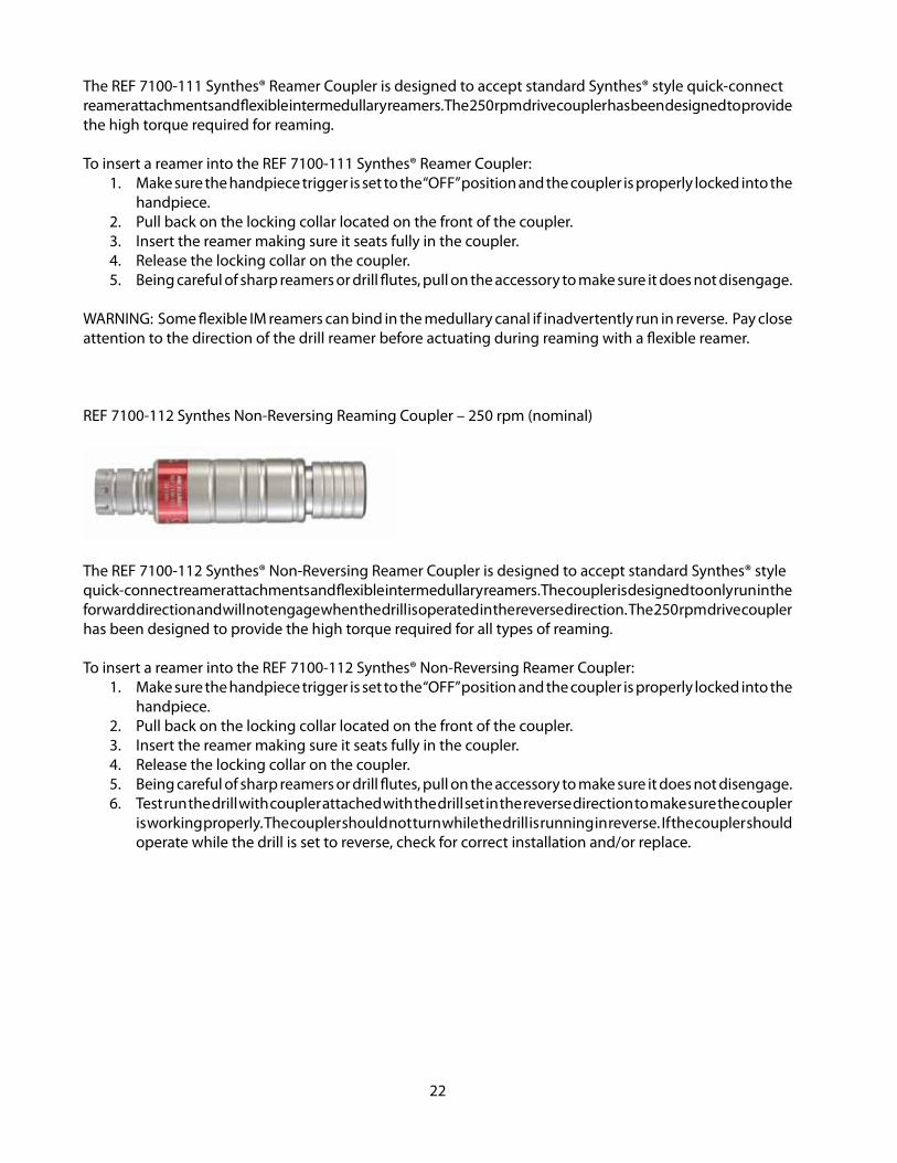
REF 7100-112 Synthes Non-Reversing Reaming Coupler – 250 rpm (nominal)
The REF 7100-112 Synthes® Non-Reversing Reamer Coupler is designed to accept standard Synthes® style quick-connect reamer attachments and flexible intermedullary reamers . The coupler is designed to only run in the forward direction and will not engage when the drill is operated in the reverse direction . The 250 rpm drive coupler has been designed to provide the high torque required for all types of reaming .
To insert a reamer into the REF 7100-112 Synthes® Non-Reversing Reamer Coupler:1 . Make sure the handpiece trigger is set to the “OFF” position and the coupler is properly locked into the
handpiece .2 . Pull back on the locking collar located on the front of the coupler . 3 . Insert the reamer making sure it seats fully in the coupler .4 . Release the locking collar on the coupler .5 . Being careful of sharp reamers or drill flutes, pull on the accessory to make sure it does not disengage .6 . Test run the drill with coupler attached with the drill set in the reverse direction to make sure the coupler
is working properly . The coupler should not turn while the drill is running in reverse . If the coupler should operate while the drill is set to reverse, check for correct installation and/or replace .

23
Wire and Pin Driving Couplers – (750 rpm)
REF 7100-045 Wire/Pin Driver CouplerAccepts wire/pins from 1 .6 mm – 2 .8mm (1/16” – 7/64”)
REF 7100-050 Pin Driver CouplerAccepts pins from 3 .2 mm – 4 .0mm (1/8” – 5/32”)
To insert a wire or pin into the wire and pin driver couplers:1 . Make sure handpiece trigger is set to the “OFF” position and the coupler is properly locked into the
handpiece .2 . Insert wire or pin into the front of the coupler .3 . Insert battery/power pack into the handpiece and set trigger to “ON” position .4 . Squeeze the wire/pin advance lever to hold wire/pin in place .5 . Depress the trigger while holding advance lever to drive wire/pin .6 . Release advance lever and pull back on handpiece to advance more wire/pin .7 . Use reverse when removing threaded wire/pins . Hold advance lever and depress the trigger while
pulling back on the handpiece .

24
REF 7100-003/7100-010 ¼” Jacobs® Drill/Ream Couplers* – 250/750 rpm (nominal)Requires REF 4100-030 ¼” Jacobs® Key (included)
The ¼” Jacobs® couplers are often used for pin and wire driving, especially with some of the larger diameters . The REF 7100-010 offers very high torque at slow speed and the REF 7100-003 provides higher speed with the same amount of torque as the pin drivers . Please see additional instructions for these couplers earlier in the DRIVE COUPLER section of this manual .
Pulse Lavage Coupler
REF 7100-474 Pulse Lavage Coupler
This coupler is designed to adapt the REF 7105-XXX Drill Reamer handpiece to the MicroAire Pulse Lavage irrigation tubing sets .
To attach Pulse Lavage tubing to the REF 7100-474 Pulse Lavage Coupler:1 . Make sure handpiece trigger is set to the “OFF” position and the coupler is properly locked into the
handpiece .2 . Insert the MicroAire Pulse Lavage pump assembly (REF 5740-XXX) into the Pulse Lavage Coupler, lining up
the tabs on the pump with the notches on the coupler .3 . Once inserted, twist in a clockwise direction to lock into place .4 . Attach any nozzles or accessories to pump assembly .
NOTE: The REF 7505 Drill Reamer will operate the REF 7100-474 Pulse Lavage Coupler while running in forward or reverse.

25
Instrument Cleaning and Sterilization Instructions per ISO17664:2003 and AAMIST81:2004Devices: WARNING:Universal precautions for handling contaminated materials should be observed at all times .
CAUTION:• DO NOT lubricate or oil the handpieces . Lubrication may damage the internal motor mechanism . Also
take special precautions to avoid the use of cleaners that contain lubrication . • DO NOT immerse the handpiece in any fluid .• DO NOT utilize cleaning solutions that are not mild pH unless they are approved for use with Anodized
Aluminum and Surgical Instruments .• DO NOT utilize cleaning agents with chlorine or chloride as the active ingredient is corrosive to stainless
steel .• DO NOT use an ultrasonic cleaner . Ultrasonic cleaning can damage the bearings in the handpiece,
potentially resulting in overheating or failure of the handpiece .• Dried blood, saline, and other deposits inside the handpiece are a major cause of equipment malfunction .
Proper cleaning and inspection prior to sterilization will avoid delays during the surgical procedure .
Limitations On Reprocessing:Repeated processing, according to the instructions below, has minimal effect on MicroAire reusable surgical instruments . End of life is normally determined by wear and damage due to use .
Point Of Use:Remove excess body fluids and tissue with a disposable, non-shedding wipe and cover with a cloth dampened with purified water . Body fluids and tissue should not be allowed to dry on instruments prior to cleaning (MAXIMUM 30 minutes) .
Preparation For Decontamination a . Disposable surgical accessories should be discarded after use, handling them as any
contaminated sharp accessory is handled . Reuse of surgical cutting accessories (burs, blades, drills) is not recommended .
b . Turn the trigger to the “OFF” position .c . Remove the air hose from the handpiece . d . Remove the surgical accessory from the coupler .e . Remove the coupler from the handpiece .
Preparation of Cleaning AgentPrepare mild pH enzyme and cleaning agents at the use-dilution and temperature recommended by the manufacturer . Determination of cleaning agents shall be by local or country regulations .
Cleaning: Automated
1) Load the medical devices into the Washer Disinfector .a) Avoid contact between devices (movement during washing could cause damage and washing action could
be obstructed) . DO NOT overload the trays .b) Arrange medical devices so that cannulations are not horizontal and are oriented downwards (to assist
drainage) .2) The minimum recommended Washer/Disinfector cycle is below:

26
# Title Detergent Minutes Temp
1 Pre-Wash Mild pH Enzymatic * 4 < = 50 °C (122 °F)
2 Rinse None 1** < = 50 °C (122 °F)
3 Wash Mild pH 4 > = 60 °C (140 °F)
4 Drain for 1 minute minimum
5 Rinse None 2** > = 60 °C (140 °F)
6 Drain for 1 minute minimum
7 Thermal Disinfect None 10 > = 93 °C (200 °F)
8 Drain for 1 minute minimum
* Detergent can be omitted at the pre-wash stage if the equipment does not have this ability .** If not using mild pH detergent, extend rinse time if possible to reduce possible degradation .
Cleaning: Manual
1 . Clean the device immediately with warm (> 60 °C / 140 °F) water, mild pH enzymatic detergent, and a soft brush . Scrub the handpiece with the brush, paying close attention to instrument crevices . Make sure the handpiece is held upright as often as possible during cleaning and rinsing to keep moisture away from the aire hose connector .
1 . Use a cannulation brush on cannulation of the REF 7105-XXX drill reamer and cannulated drive couplers . a . Clean the cannulated shaft of the wire/pin drivers with the small cylindrical wire driver cannulation
brush (9600-063), or equivalent brush or pipe-cleaner .b . Continue to brush clean the cannulation in the handpiece and drive couplers until the brush comes
out “clean” and no longer contains signs of blood or tissue .2 . Rinse thoroughly under running (< 50 °C / 122 °F) water for a minimum of 2 minutes .3 . Clean the handpiece thoroughly with warm (> 60 °C / 140 °F) water, mild pH detergent, and a soft brush .
Scrub the handpiece with the brush, paying close attention to the instrument crevices . 4 . Flush the lumens of instruments and the nose of drills and wire drivers with a Water-Pik or similar device .
Flushing removes blood, debris, and saline deposits . 5 . Rinse all items thoroughly under running (< 50 °C / 122 °F) water for a minimum of 2 minutes . If
possible, use distilled water for the final rinse .
Disinfection:Disinfection is only acceptable as an adjunct to full terminal sterilization for reusable surgical instruments . See sterilization section below .
Drying:Wipe off any water from the handpiece with a soft lint-free towel . An air gun can also be used to dry the handpiece .
Maintenance, Inspection and Function Testing:1 . Carefully inspect each device to ensure that all visible blood and soil has been removed .2 . Visually inspect for damage and/or wear .3 . Check the action of moving parts to ensure smooth operation throughout the intended range of motion .4 . Where instruments form part of a larger assembly, check that the devices assemble with mating componentsNote: If concerns are noted that may compromise the function of the device, please contact your MicroAire
27
representative .
Accidental ImmersionIf a handpiece is accidentally immersed in saline, disinfectant, cleaning fluid or any other corrosive substance, take the following steps to save the handpiece .
a . Totally immerse the handpiece in distilled water for 1 minute to dilute the corrosive fluid . DO NOT allow water to dry in the handpiece .
b . Immediately after soaking, steam sterilize in a prevacuum sterilizer at 270°F (132°C) for 4 minutes followed by a minimum drying time of 8 minutes . Sterilizing will dry out the handpiece, avoid rusting, and prevent contamination from collecting in the motor .
c . Return the handpiece to MicroAire or MicroAire authorized service center for service .
Packaging:
1 . Single Instruments – A standard medical grade steam sterilization wrap may be used . Ensure that the wrap is large enough to contain the instrument without stressing the packaging . (ANSI/AAMI ST46-1993)
2 . Sets of Instruments – sets of instruments may be loaded into dedicated instrument trays or general purpose sterilization trays for sterilization . If applicable, use standard medical grade steam sterilization wrap following the AAMI double wrap method (ANSI/AAMI ST46-1993)
Instrument Sterilization Instructions
MicroAire powered surgical instruments (including handpieces and drive couplers) are normally sterilized by steam, using either a gravity displacement or prevacuum sterilizer .
1 . Steam Sterilization
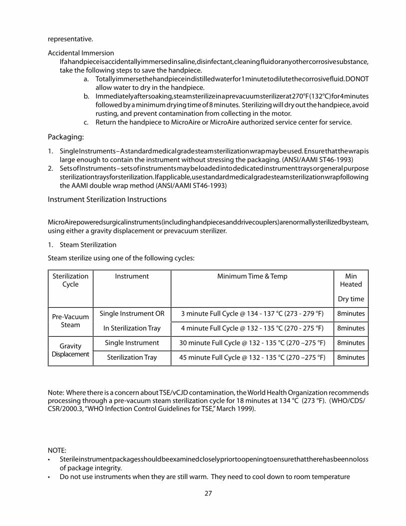
Steam sterilize using one of the following cycles:
Sterilization Cycle
Instrument Minimum Time & Temp Min Heated
Dry time
Pre-Vacuum Steam
Single Instrument OR
In Sterilization Tray
3 minute Full Cycle @ 134 - 137 °C (273 - 279 °F) 8 minutes
4 minute Full Cycle @ 132 - 135 °C (270 - 275 °F) 8 minutes
Gravity Displacement
Single Instrument 30 minute Full Cycle @ 132 - 135 °C (270 –275 °F) 8 minutes
Sterilization Tray 45 minute Full Cycle @ 132 - 135 °C (270 –275 °F) 8 minutes
Note: Where there is a concern about TSE/vCJD contamination, the World Health Organization recommends processing through a pre-vacuum steam sterilization cycle for 18 minutes at 134 °C (273 °F) . (WHO/CDS/CSR/2000 .3, “WHO Infection Control Guidelines for TSE,” March 1999) .
NOTE: • Sterile instrument packages should be examined closely prior to opening to ensure that there has been no loss
of package integrity .• Do not use instruments when they are still warm . They need to cool down to room temperature
28
• Do not soak instruments to cool them down or wrap cold towels around them .
2 . Flash SterilizationMicroAire Surgical Instruments does not recommend “flash” sterilization for powered surgical instruments . The series 7000 has not been validated for flash sterilization . Please contact MicroAire for the most up-to-date information on this sterilization method .
3 . Ethylene Oxide SterilizationEthylene is NOT recommended for powered surgical instruments because lengthy aeration time is needed to assure that no ethylene oxide is left in the internal mechanisms or on the surface of the instrument .
4 . Peracetic AcidDO NOT process powered surgical instruments in equipment that uses peracetic acid as a liquid sterilant .
5 . Sterrad™SterilizersSterrad™ systems use concentrated hydrogen peroxide that will strip some of the metal surfaces throughout the handpiece . Sterrad™ is not recommended for powered surgical instruments .
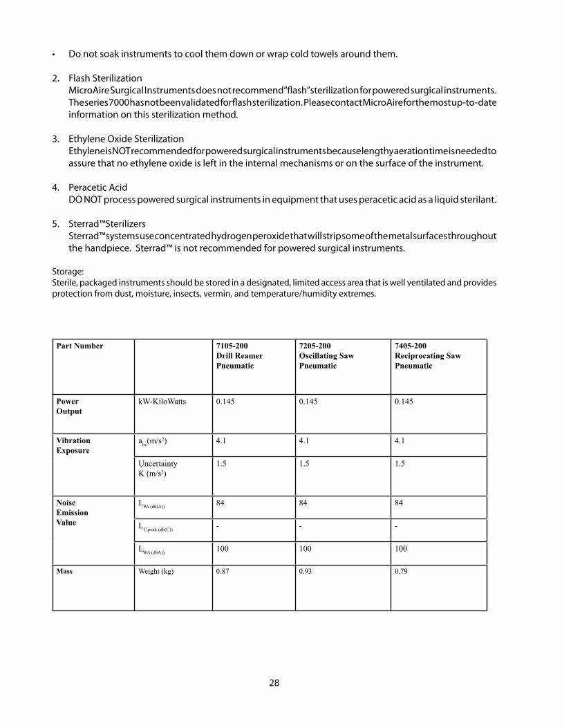
Storage:Sterile, packaged instruments should be stored in a designated, limited access area that is well ventilated and provides protection from dust, moisture, insects, vermin, and temperature/humidity extremes .
Part Number 7105-200Drill Reamer Pneumatic
7205-200Oscillating Saw Pneumatic
7405-200Reciprocating Saw Pneumatic
Power Output
kW-KiloWatts 0.145 0.145 0.145
Vibration Exposure
ahv(m/s2) 4.1 4.1 4.1
UncertaintyK (m/s2)
1.5 1.5 1.5
Noise Emission Value
LPA (db(A)) 84 84 84
LC,peak (db(C)) - - -
LWA (dbA)) 100 100 100
Mass Weight (kg) 0.87 0.93 0.79
29
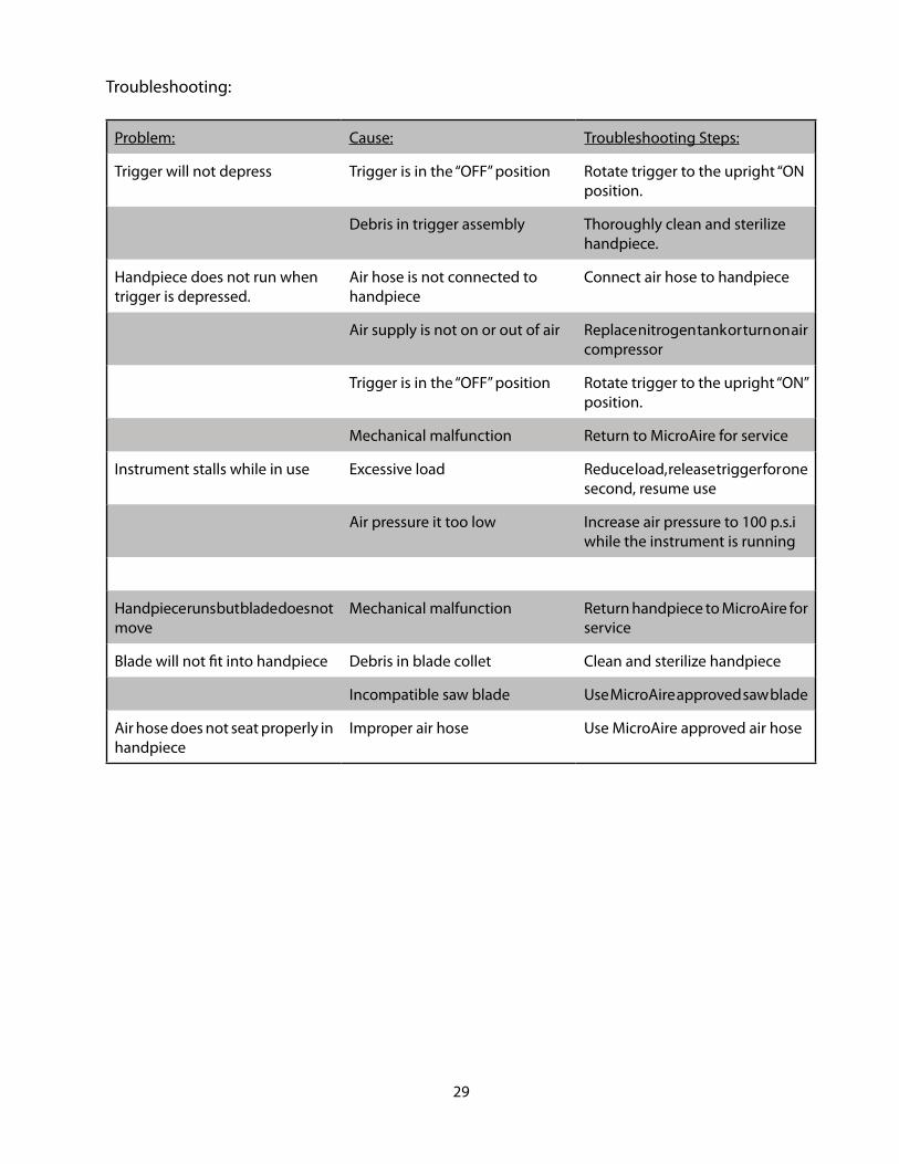
Troubleshooting:
Problem: Cause: Troubleshooting Steps:
Trigger will not depress Trigger is in the “OFF” position Rotate trigger to the upright “ON position .
Debris in trigger assembly Thoroughly clean and sterilize handpiece .
Handpiece does not run when trigger is depressed .
Air hose is not connected to handpiece
Connect air hose to handpiece
Air supply is not on or out of air Replace nitrogen tank or turn on air compressor
Trigger is in the “OFF” position Rotate trigger to the upright “ON” position .
Mechanical malfunction Return to MicroAire for service
Instrument stalls while in use Excessive load Reduce load, release trigger for one second, resume use
Air pressure it too low Increase air pressure to 100 p .s .i while the instrument is running
Handpiece runs but blade does not move
Mechanical malfunction Return handpiece to MicroAire for service
Blade will not fit into handpiece Debris in blade collet Clean and sterilize handpiece
Incompatible saw blade Use MicroAire approved saw blade
Air hose does not seat properly in handpiece
Improper air hose Use MicroAire approved air hose

30
Warranty, Service and Repair
Periodic inspection and service is essential to keep precision MicroAire instruments running properly . If repairs are required, they can be accomplished quickly with a minimum of disruption to the hospital’s schedule .
In hospital service
All MicroAire equipment should be inspected and tested periodically in accordance with the facility’s bio-engineering policy . Such service should be documented within the bio-engineering department .
CAUTION: Repairs or alterations to MicroAire products made by anyone other than MicroAire or an Authorized MicroAire Repair Facility will void that product’s warranty, and the customer will be responsible for any costs related to returning the product to working condition .
MicroAire Repair Service
Responsive service comes with every MicroAire product . If a problem with your equipment should arise, contact our Customer Service Department at:
Telephone: Fax: E-mail:USA: 800-722-0822 800-438-4309 inquiry@microaire .comOutside USA: 434-975-8000 434-975-4134 intlsvc@microaire .com
NOTE: Mailing address information located on back cover .
We may be able to help solve the problem quickly without returning the instrument for service . DO NOT disassemble or attempt to service the equipment . It can only be serviced by MicroAire or an Authorized MicroAire Repair Facility . Unauthorized service will void the warranty .
To return an item for service, follow this procedure:
1 . Contact Customer Service for a Return Material Authorization (RMA) number .
NOTE: DO NOT return equipment without an RMA number . This could cause delays in service, and/or problems tracking your return .
2 . Clean and disinfect equipment before sending for repair .3 . Along with the items sent for repair, enclose description of the problem encountered, the type of use,
the place of use, a contact name, and a telephone number . This information is helpful to our repair technicians in expediting your repair .
4 . If the instrument is out of warranty, enclose a purchase order number with the instrument . If the instrument is under warranty, include the purchase date .
5 . In the United States, ship the merchandise by Express Mail, Federal Express, or UPS Blue Label to prevent shipping delays . From outside the United States, return goods by UPS, Federal Express or Air Freight .
6 . Return the merchandise prepaid .

31
7 . If an estimate of repair costs is needed before the repair technicians start work, include the name and telephone number of the person to contact .
8 . We will repair and reship the item by 2nd day air within the United States and by UPS or Air Freight outside the US, unless specified otherwise .
Periodic Inspection
Because of the stressful nature of surgical use, decontamination, and sterilization, we recommend that all instruments be returned for routine inspection and service at least once a year . There is no charge for this service during the warranty period .
MicroAire Product Lifespan
The series 7000 Large Power Instrument System should provide years of reliable service . This life-expectancy is based on the proper handling and care of the instruments, including annual maintenance at MicroAire or a MicroAire Authorized Service Center . Any abuse, misuse, or use in other than recommended operating parameters may affect the life of the equipment .
REF 7105-XXX, REF 7205-XXX, REF 7405-XXX, and Series 7000 Drive Couplers Warranty
MicroAire Surgical Instruments LLC warrants its REF 7105-XXX, REF 7205-XXX, REF 7405-XXX, and all REF 7100-XXX Drive Couplers to be free from defects in material and workmanship in their manufacture for a period of one year (1) from the original purchase date by the end customer . The warranty is limited to the repair or replacement of the product without charge .
This warranty is void in the event of abuse, misuse, or use in other than normal surgical environment, or in the event disassembly, alteration, or repair of the product not authorized by MicroAire, or in the event that the product has not been used in a reasonable manner and in compliance with the written instructions furnished by MicroAire .
All other expressed or implied warranties of fitness and merchantability are excluded here from, and MicroAire shall have no liability of any kind for incidental or consequential damages .
Extended Warranty/Service Agreement
Extended warranties and services agreements are available on MicroAire power equipment . Extended warranties may be purchased while the equipment is covered by the original first year of warranty . If the equipment is out of warranty, it must first be restored, if necessary, to full serviceable condition before being eligible for a service agreement .

©2010 MicroAire Surgical Instruments LLCIM-7105, Rev . D, Printed in USA 04/12
Zimmer® is a registered trademark of Zimmer, Inc .Synthes® is a registered trademark of Synthes (USA) .These companies are not affiliated with MicroAire Surgical Instruments LLC
MicroAire Surgical Instruments, LLC3590 Grand Forks BoulevardCharlottesville, Virginia 22911 USAPhone: (800) 722-0822 (434) 975-8000Order Fax: (800) 648-4309 or (434) 975-4131www .microaire .com
MediMarkEurope 11, rue Emile ZolaBP 2332F-38033 Grenoble Cedex 2France


