62
— INSTRUCTION MANUAL Power Factor Controller RVT-D Installation and operating instructions

— I NS TRUC TI O N M A N UA L
Power Factor Controller RVT-DInstallation and operating instructions
2 RV T- D I NS TR U C TI O N M A N UA L
Read this firstAbout this Instruction Manual................................................................3Safety .......................................................................................................3Electromagnetic compatibility...............................................................31. Description1.1. RVT-D features .................................................................................41.2. Front view .........................................................................................41.3. Full graphics display and keypad ...................................................52. Installation2.1. Mounting......................................................................................62.2. Rear view............................................................................................72.3. Leads connection .............................................................................72.4. Wiring diagram..................................................................................83. Easy start3.1. Menu navigation ..............................................................................93.2. Starting the RVT-D ..........................................................................93.3. Easy commissioning3.3.1. Description....................................................................................103.3.2. Parameters ..................................................................................103.3.3. Automatic commissioning..........................................................114. Menus chart .........................................................................125. Measurements5.1. Measurements description............................................................135.2. Overview .........................................................................................155.3. System values..................................................................................155.4. Event logging .................................................................................165.4.1. Description....................................................................................165.4.2. Recorded values............................................................................175.4.3. Example.........................................................................................175.5. Measurements printing .................................................................17
—Table of contents
6. Setting6.1. Change mode (AUTO – MAN – SET) ..............................................186.1.1. Settings protection ....................................................................186.1.2. Automatic mode (AUTO).............................................................196.1.3. Manual mode (MAN)....................................................................196.1.4. Set mode (SET) ...........................................................................206.2. Commissioning (SET Mode)6.2.1. Automatic ....................................................................................206.2.2. Guided...........................................................................................206.3. Manual settings (SET Mode)6.3.1. Description of parameters ........................................................226.3.2. Control: closed loop ...................................................................226.3.3. Control: open loop......................................................................286.3.4. Control: external trigger ...........................................................346.3.5. Restore sefault settings.............................................................436.4. Input / output configuration .......................................................446.4.1. Various configuration ................................................................446.4.2. Communication (Printer or Modbus) .......................................446.5. Test function...................................................................................456.6. Settings printing ...........................................................................48
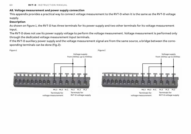
7. Bank monitoring...................................................................48AppendicesA1. Dimensions.......................................................................................49A2. Technical specifications.................................................................50A3. Testing & troubleshooting ............................................................52A4. Post alarm restarting procedure ..................................................55A5. Check in case of maloperation of RVT-D .....................................56A6. Phase shift table..............................................................................57A7. RVT-D cabling possibilities ............................................................58A8. Voltage measurement and power supply connection ...............59
3 RV T- D I NS TR U C TI O N M A N UA L
About this Instruction ManualThis Instruction Manual is designed to help you quickly install and operate the RVT-D Controller.Before installation and operation of the RVT-D Controller, read this notice carefully.Keep it at the disposal of people in charge of installation, main-tenance and operation.
SafetyInstallation, maintenance and operation of the RVT-D Controller must be performed by qualified electricians.Do not work under voltage.For cleaning, remove the dust with a dry cloth. Do not use abra-sives, solvents or alcohol. Before cleaning please turn off the power supply and voltage measurement circuit.Do not open the RVT-D Controller’s housing. There are no user serviceable parts inside.Disconnect the voltage before replacing the fuse.The RVT-D Controller is connected to two current transformers. Do not unplug the current transformers connections before making sure they are short-circuited or connected to another parallel load of sufficiently low impedance. Failure to do so can create dangerous over voltages.Do not use this product for any other purpose than its original aim.
—Read this first
Electromagnetic compatibilityThis RVT-D Controller has been verified for compliance with EU (European Union) directives for EMC (electromagnetic compati-bility) for operation at 50 Hz and bears the CE marking to this effect.
When an apparatus is used in a system, EU directives may re-quire that the system be verified for EMC compliance.The following guidelines are helpful in improving the EMC per-formance of a system:
Metallic enclosures generally improve EMC performance.1. Run cables away from apertures in the enclosure.2. Run cables close to grounded metallic structures.3. Use multiple ground straps for doors or other panels parts as required.4. Avoid common ground impedances.
The RVT-D Controller is UL Recognized.
The RVT-D Controller is CSA certified for use in 120Vac system voltage.
4 RV T- D I NS TR U C TI O N M A N UA L
1.1. RVT-D featuresThe RVT-D Controller is the control unit of an automatic capaci-tor bank equipped with static switches (dynamic compensa-tion).It performs the switching of capacitors with a view to reaching a user-defined target cos ϕ and/or to reducing voltage drops.• All the switching parameters may be programmed automati-
cally or manually (description in paragraphs 6.2 and 6.3).• The target cos ϕ and the control mode (open loop / closed
loop / external trigger) may be programmed (description in paragraph 6.3).
Additionally the RVT-D Controller provides useful functions:• Measurements (description in paragraph 5.1).• Protection against unexpected phenomena and/or unautho-
rized use (description in paragraphs 6.1.1, 6.1.4, 6.3.2.1, 6.3.3.1 and 6.3.4.1).
• Logging of data and alarm messages (description in para-graphs 5.4 and 7).
• Checking and testing of outputs status (description in para-graphs 6.5 and 7).
Moreover with the addition of optional accessories, the RVT-D provides:• Printout of measurements and parameters.• Temperature measurements.Each accessory is delivered with its own Instruction Manual.
—1. Description
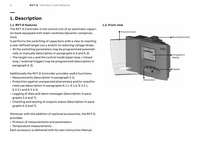
1.2. Front view
Protective door
Help button
Mounting bracket
Full graphics display
Keypad
5 RV T- D I NS TR U C TI O N M A N UA L
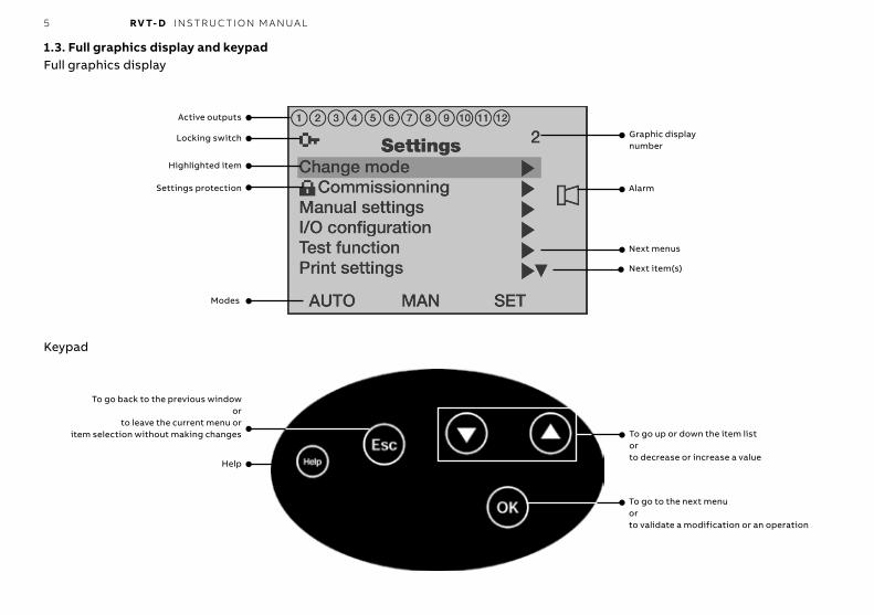
1.3. Full graphics display and keypadFull graphics display
Keypad
Active outputs
Next item(s)
Next menus
Alarm
Graphic display number
Locking switch
Highlighted item
Settings protection
Modes
To go to the next menuorto validate a modification or an operation
To go up or down the item listorto decrease or increase a value
Help
To go back to the previous windowor
to leave the current menu oritem selection without making changes

6 RV T- D I NS TR U C TI O N M A N UA L
2.1. MountingStep 1 : Slide the RVT-D (a) perpendicularlyto the capacitor bank Ccbicle (b).Step 2 : Rotate the RVT-D to insert it into thecapacitor bank cubicle.
—2. Installation
Step 3 : Insert the mounting bracket (c) in the corresponding fixation holes (d) of the RVT-D.Step 4 : Pull the mounting bracket backwards.Step 5 : Turn the screw (e) into the mounting bracket and tighten until the RVT-D is secured in place.
(c)Step 2
Step 1
(a)
(b)
Step 3
(d)
(e)
Step 4
Step 5
Repeat steps 3 to 5 forthe bottom mountingbracket.
7 RV T- D I NS TR U C TI O N M A N UA L
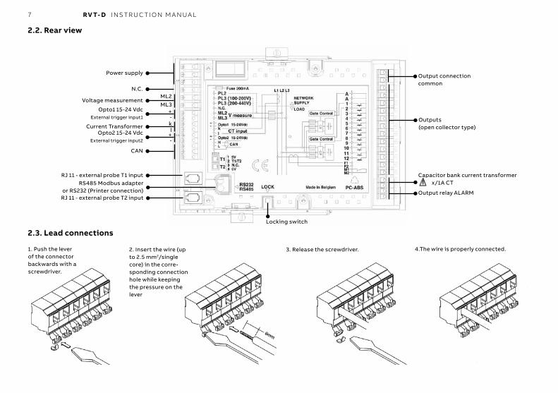
2.2. Rear view
Power supply
Output relay ALARM
N.C.
Voltage measurement
Opto1 15-24 VdcExternal trigger input1
1. Push the lever of the connector backwards with a screwdriver.
2.3. Lead connections
4.The wire is properly connected.2. Insert the wire (up to 2.5 mm2/single core) in the corre-sponding connection hole while keeping the pressure on the lever
3. Release the screwdriver.
ML2ML3
+
Current Transformer kl
-
Opto2 15-24 VdcExternal trigger input2
+-
CAN
RJ 11 - external probe T1 inputRS485 Modbus adapter
or RS232 (Printer connection)RJ 11 - external probe T2 input
Locking switch
Output connectioncommon
Outputs(open collector type)
Capacitor bank current transformer x/1A CT

8 RV T- D I NS TR U C TI O N M A N UA L
2.2. Wiring diagram
PL2, PL3 : power supply ML2, ML3 : measurementOPTO1 : external trigger input1k, l : network curent transformerOPTO2 : external trigger input2/Dynaswitch status inputT1, T2 : temperature probe inputs
H, L : CAN : for controlling up to 32 DynaswitchesA, A : output connection common1-12 : outputs (open collector type)F1, F2 : capacitor bank current transformer (1A)M1, M2 : output relay ALARM
Important comment: please note that the network CT must be placed in the same phase as the capacitor bank CT

9 RV T- D I NS TR U C TI O N M A N UA L
3.2. Starting the RVT-DWhen the RVT-D is powered-up, the Welcome menu is displayed.The RVT-D is in MAN mode and needs to be set in SET mode in order to commission it or to modify its parameters (see paragraph 6.1)
—3. Easy start3.1. Menu navigation

10 RV T- D I NS TR U C TI O N M A N UA L
3.3. Easy commissioning3.3.1. DescriptionThe RVT-D performs automatic commissioning including:• automatic recognition of :
- special connection (C.T. leads) - number of outputs - type of switching sequence
• automatic setting of : - Qstep - Istep - Invert Icap
3.3.2. ParametersRequested parameters during the easy commissioning process are:CT scale-net : Current Transformer ratio (for instance a 250A / 5A CT has a CT scale-net of 50).Target cos ϕ : Target displacement power factorCT scale-cap : Capacitor bank current transformer ratio. x/1A CTV scaling : external voltage transformer ratio.Control : regulation type: open loop, closed loop and external trigger
Increase or decreasethe V scaling value
using the buttons
Enable or disablethe CAN control
using the buttons
Select the node type
using the buttons

11 RV T- D I NS TR U C TI O N M A N UA L
3.3.3. Automatic commissioningNote: 1°) if you have a short-circuit on the CT’s secondary winding do not forget to open it after having connected the current input of the PF Controller2°) if a transformer is used for the voltage measurement, the Vscaling value has to be changed accordingly (see paragraph 6.3.).
Increase or decreasethe CT scale-net value
using the buttons
Increase of decreasethe target cos ϕ value
using the buttons
Automatic commissioning is now completed. The RVT-D will return automatically to AUTO mode if no key is pressed for 5 minutes. To return to AUTO mode manually select Automatic in the Change mode menu.
Comment: when the icon appears in the upper left-hand corner of the display, this means that the RVT-D is locked. SET Mode access is denied and commissioning cannot be per-formed until the RVT-D is unlocked (see description in para-graph 6.1.1)
Increase or decrease the CT scale-cap value
using the buttons
Select the control mode
using the buttons
then press
12 RV T- D I NS TR U C TI O N M A N UA L
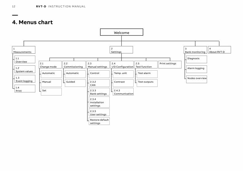
—4. Menus chart
Welcome
1Measurements
2Settings
3Bank monitoring
4About RVT-D
1.1Overview
1.2System values
1.3Event logging
1.4Print
2.1Change mode
2.2Commissioning
2.3Manual settings
2.4I/O Configuration
2.5Test function
Print settings
Automatic
Manual
Set
Automatic
Guided
Control
2.3.2CAN
2.3.3Bank settings
2.3.4Installation settings
2.3.5User settings
Restore default settings
Temp. unit
Contrast
2.4.3Communication
Test alarm
Test outputs
Diagnosis
Alarm logging
Nodes overview
13 RV T- D I NS TR U C TI O N M A N UA L
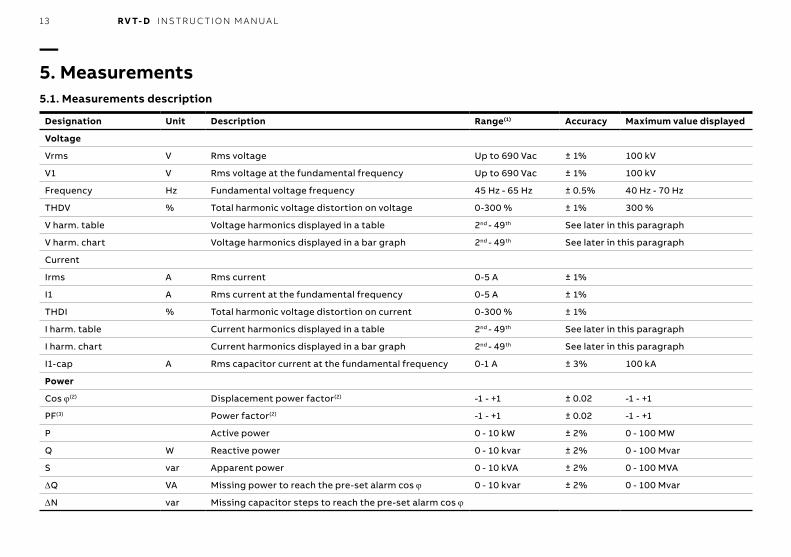
—5. Measurements5.1. Measurements description
Designation Unit Description Range(1) Accuracy Maximum value displayed
Voltage
Vrms V Rms voltage Up to 690 Vac ± 1% 100 kV
V1 V Rms voltage at the fundamental frequency Up to 690 Vac ± 1% 100 kV
Frequency Hz Fundamental voltage frequency 45 Hz - 65 Hz ± 0.5% 40 Hz - 70 Hz
THDV % Total harmonic voltage distortion on voltage 0-300 % ± 1% 300 %
V harm. table Voltage harmonics displayed in a table 2nd - 49th See later in this paragraph
V harm. chart Voltage harmonics displayed in a bar graph 2nd - 49th See later in this paragraph
Current
Irms A Rms current 0-5 A ± 1%
I1 A Rms current at the fundamental frequency 0-5 A ± 1%
THDI % Total harmonic voltage distortion on current 0-300 % ± 1%
I harm. table Current harmonics displayed in a table 2nd - 49th See later in this paragraph
I harm. chart Current harmonics displayed in a bar graph 2nd - 49th See later in this paragraph
I1-cap A Rms capacitor current at the fundamental frequency 0-1 A ± 3% 100 kA
Power
Cos ϕ(2) Displacement power factor(2) -1 - +1 ± 0.02 -1 - +1
PF(3) Power factor(2) -1 - +1 ± 0.02 -1 - +1
P Active power 0 - 10 kW ± 2% 0 - 100 MW
Q W Reactive power 0 - 10 kvar ± 2% 0 - 100 Mvar
S var Apparent power 0 - 10 kVA ± 2% 0 - 100 MVA
ΔQ VA Missing power to reach the pre-set alarm cos ϕ 0 - 10 kvar ± 2% 0 - 100 Mvar
ΔN var Missing capacitor steps to reach the pre-set alarm cos ϕ
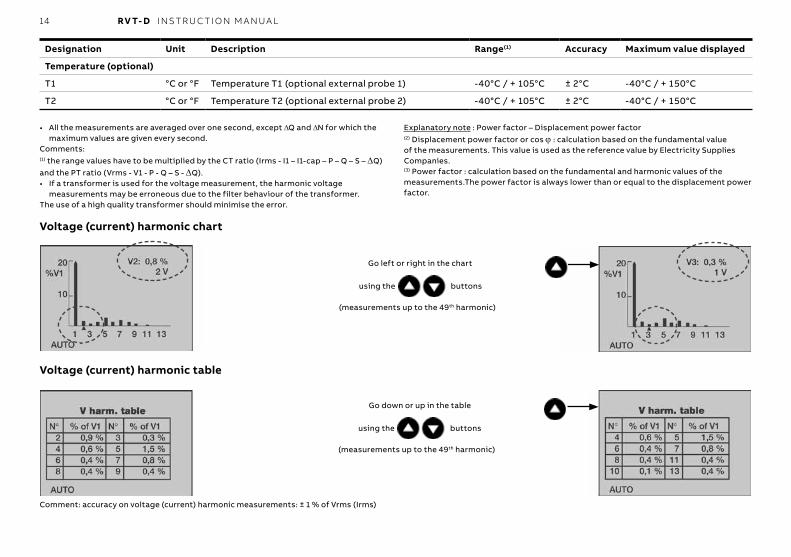
14 RV T- D I NS TR U C TI O N M A N UA L
Designation Unit Description Range(1) Accuracy Maximum value displayed
Temperature (optional)
T1 °C or °F Temperature T1 (optional external probe 1) -40°C / + 105°C ± 2°C -40°C / + 150°C
T2 °C or °F Temperature T2 (optional external probe 2) -40°C / + 105°C ± 2°C -40°C / + 150°C
• All the measurements are averaged over one second, except ΔQ and ΔN for which the maximum values are given every second.
Comments:(1) the range values have to be multiplied by the CT ratio (Irms - I1 – I1-cap – P – Q – S – ΔQ) and the PT ratio (Vrms - V1 - P - Q – S - ΔQ).• If a transformer is used for the voltage measurement, the harmonic voltage
measurements may be erroneous due to the filter behaviour of the transformer.The use of a high quality transformer should minimise the error.
Explanatory note : Power factor – Displacement power factor(2) Displacement power factor or cos ϕ : calculation based on the fundamental value of the measurements. This value is used as the reference value by Electricity Supplies Companies.(3) Power factor : calculation based on the fundamental and harmonic values of the measurements.The power factor is always lower than or equal to the displacement power factor.
Voltage (current) harmonic chart
Voltage (current) harmonic table
Go left or right in the chart
using the buttons
(measurements up to the 49th harmonic)
Go down or up in the table
using the buttons
(measurements up to the 49th harmonic)
Comment: accuracy on voltage (current) harmonic measurements: ± 1 % of Vrms (Irms)
15 RV T- D I NS TR U C TI O N M A N UA L
5.2. Overview
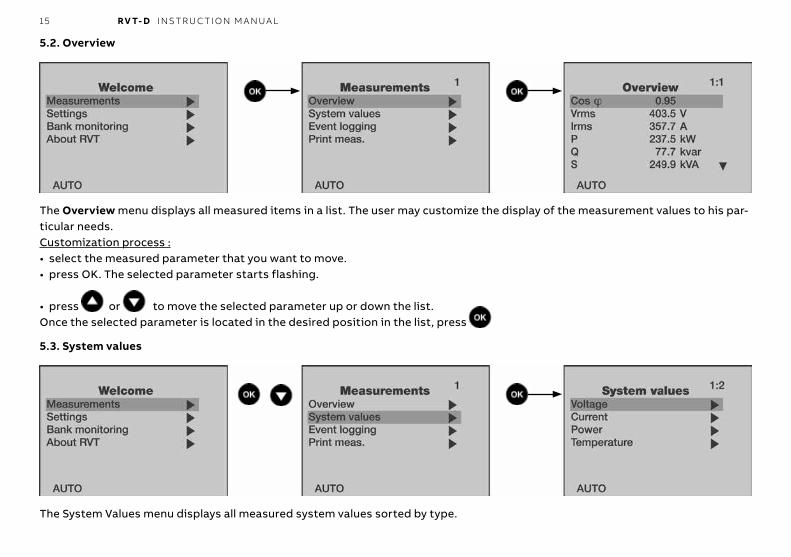
The Overview menu displays all measured items in a list. The user may customize the display of the measurement values to his par-ticular needs.Customization process :• select the measured parameter that you want to move.• press OK. The selected parameter starts flashing.
• press or to move the selected parameter up or down the list.Once the selected parameter is located in the desired position in the list, press .
5.3. System values
The System Values menu displays all measured system values sorted by type.
16 RV T- D I NS TR U C TI O N M A N UA L
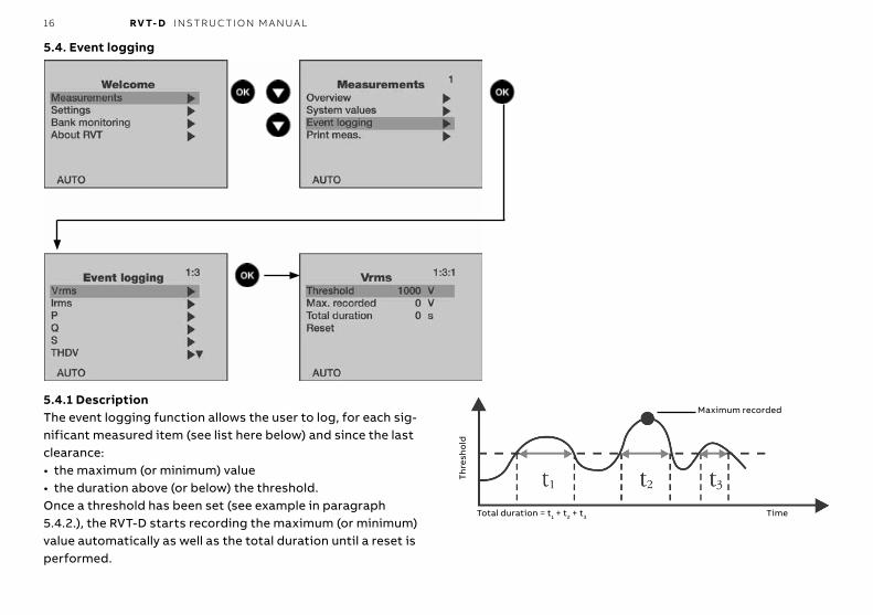
5.4. Event logging
5.4.1 DescriptionThe event logging function allows the user to log, for each sig-nificant measured item (see list here below) and since the last clearance:• the maximum (or minimum) value• the duration above (or below) the threshold.Once a threshold has been set (see example in paragraph 5.4.2.), the RVT-D starts recording the maximum (or minimum) value automatically as well as the total duration until a reset is performed.
Maximum recorded
Total duration = t1 + t2 + t3 Time
Th
resh
old

17 RV T- D I NS TR U C TI O N M A N UA L
5.4.2. Recorded valuesThe event logging function allows the user to record the time during wich a measured value exceeds a threshold and its maximum value for the following parameters : Vrms [V], Irms [A], P [W], Q [var], S [VA], THDV [%], THDI [%], ΔQ [var], frequency(1) [Hz], T1(1) [°C or °F] and T2(1) [°C or °F].(1) Minimum values and duration below a threshold are also recorded for the frequency and the temperatures.
5.4.3. ExampleRecording of information on Vrms.Voltage network : 400V.
Print once: when selected and validated, all the measurements are printed once.Repeat printing: when set “on”, all the measurements are repeatedly printed according to the Repeat-Delay.Repeat-Delay: time between two successive measurement printings.the duration above (or below) the threshold.
The recorded information (maximum value and total duration) may be cleared by selecting and validating the “Reset” item.5.5. Measurements printing

18 RV T- D I NS TR U C TI O N M A N UA L
The Change Mode menu allows the operating mode of the RVT-D to be selected.Comment: after a power outage, once the power returns the RVT-D starts in the Mode previously selected, except for the SET Mode. In this case, the RVT-D will start in AUTO mode and changes previously made in SET Mode that have not been validated are not saved.
—6. Settings6.1 Change Mode (AUTO – MAN – SET)
Select the mode
with the buttons then press
6.1.1. Settings ProtectionUnauthorised modification of all or some of the parameters can be prevented in a number of ways.Locking switch:A locking switch, located at the back of the RVT-D (see RVT-D rear view in paragraph 2.2), allows the RVT-D to be locked in AUTO mode or in MAN mode.When the lock is set:• a will appear in the upper left-hand corner of the graphics
display.• a will appear beside the Change mode menu, Commission-
ing menu and all the settings.• access to the Change mode and Commissioning menus will be
denied.
• no modification can be made to the settings (including the Event logging settings).
• the setting values may be consulted.AUTO/MAN mode:The RVT-D has three functional modes which are described in the following paragraphs.When the AUTO or the MAN mode is set:• a will appear beside all the settings.• access to the Commissioning menu will be denied.• access to the Change mode menu will be allowed.• the setting values may be consulted.• no modification can be made to the settings (except to the
Event logging settings).
19 RV T- D I NS TR U C TI O N M A N UA L
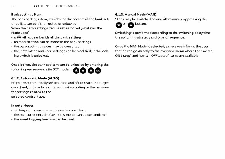
Bank settings item:The bank settings item, available at the bottom of the bank set-tings list, can be either locked or unlocked.When the bank settings item is set as locked (whatever the Mode used):• a will appear beside all the bank settings.• no modification can be made to the bank settings• the bank settings values may be consulted.• the installation and user settings can be modified, if the lock-
ing switch is unlocked.
Once locked, the bank set item can be unlocked by entering the following key sequence (in SET mode) :
6.1.2. Automatic Mode (AUTO)Steps are automatically switched on and off to reach the target cos ϕ (and/or to reduce voltage drop) according to the parame-ter settings related to theselected control type.
In Auto Mode:• settings and measurements can be consulted.• the measurements list (Overview menu) can be customized.• the event logging function can be used.
6.1.3. Manual Mode (MAN)Steps may be switched on and off manually by pressing the
or buttons.
Switching is performed according to the switching delay time, the switching strategy and type of sequence.
Once the MAN Mode is selected, a message informs the user that he can go directly to the overview menu where the “switch ON 1 step” and “switch OFF 1 step” items are available.
20 RV T- D I NS TR U C TI O N M A N UA L
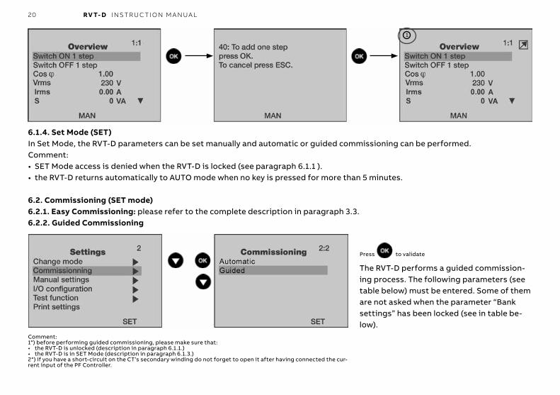
6.1.4. Set Mode (SET)In Set Mode, the RVT-D parameters can be set manually and automatic or guided commissioning can be performed.Comment:• SET Mode access is denied when the RVT-D is locked (see paragraph 6.1.1 ).• the RVT-D returns automatically to AUTO mode when no key is pressed for more than 5 minutes.
6.2. Commissioning (SET mode)6.2.1. Easy Commissioning: please refer to the complete description in paragraph 3.3.6.2.2. Guided Commissioning
Press to validate
The RVT-D performs a guided commission-ing process. The following parameters (see table below) must be entered. Some of them are not asked when the parameter “Bank settings” has been locked (see in table be-low).
1
Comment:1°) before performing guided commissioning, please make sure that:• the RVT-D is unlocked (description in paragraph 6.1.1.)• the RVT-D is in SET Mode (description in paragraph 6.1.3.)2°) if you have a short-circuit on the CT’s secondary winding do not forget to open it after having connected the cur-rent input of the PF Controller.
21 RV T- D I NS TR U C TI O N M A N UA L
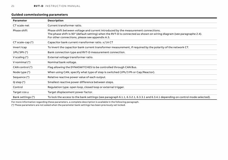
Parameter Description
CT scale-net Current transformer ratio.
Phase shift Phase shift between voltage and current introduced by the measurement connections.The phase shift is 90° (default setting) when the RVT-D is connected as shown on wiring diagram (see paragraphe 2.4).For other connections, please see appendix A.5.
CT scale-cap (*) Capacitor bank current rransformer ratio. x/1A CT
Invert Icap To invert the capacitor bank current transformer measurement, if required by the polarity of the network CT.
1Ph/3Ph (*) Bank connection type and RVT-D measurement connection.
V scaling (*) External voltage transformer ratio.
V nomimal (*) Nominal bank voltage.
CAN control (*) Flag allowing the DYNASWITCHES to be controlled through CAN Bus.
Node type (*) When using CAN, specify what type of step is switched (1Ph/3 Ph or Cap/Reactor).
Sequence (*) Relative reactive power value of each output.
Q step (*) Smallest reactive power difference between steps.
Control Regulation type: open loop, closed loop or external trigger.
Target cos ϕ Target displacement power factor.
Bank settings (*) To lock the access to the bank settings (see paragraph 6.1.1, 6.3.2.1, 6.3.3.1 and 6.3.4.1 depending on control mode selected).
Guided commissioning parameters
For more information regarding these parameters, a complete description is available in the following paragraph.(*) These parameters are not asked when the parameter bank settings has been previously set locked.
22 RV T- D I NS TR U C TI O N M A N UA L
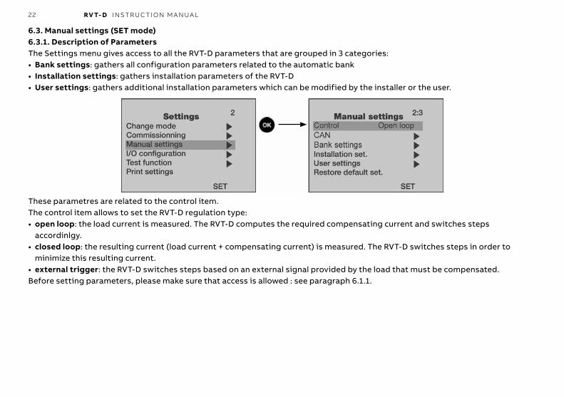
6.3. Manual settings (SET mode)6.3.1. Description of ParametersThe Settings menu gives access to all the RVT-D parameters that are grouped in 3 categories:• Bank settings: gathers all configuration parameters related to the automatic bank• Installation settings: gathers installation parameters of the RVT-D• User settings: gathers additional installation parameters which can be modified by the installer or the user.
These parametres are related to the control item.The control item allows to set the RVT-D regulation type:• open loop: the load current is measured. The RVT-D computes the required compensating current and switches steps
accordinlgy.• closed loop: the resulting current (load current + compensating current) is measured. The RVT-D switches steps in order to
minimize this resulting current.• external trigger: the RVT-D switches steps based on an external signal provided by the load that must be compensated.Before setting parameters, please make sure that access is allowed : see paragraph 6.1.1.
23 RV T- D I NS TR U C TI O N M A N UA L
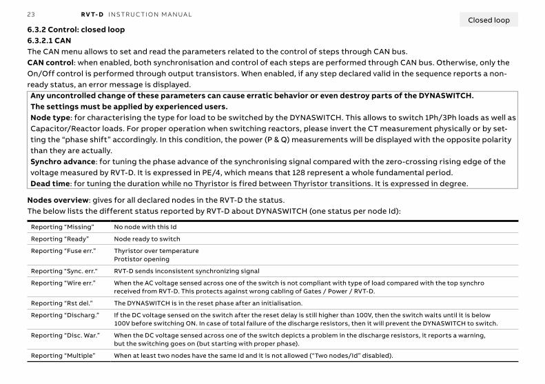
6.3.2 Control: closed loop6.3.2.1 CANThe CAN menu allows to set and read the parameters related to the control of steps through CAN bus.CAN control: when enabled, both synchronisation and control of each steps are performed through CAN bus. Otherwise, only the On/Off control is performed through output transistors. When enabled, if any step declared valid in the sequence reports a non-ready status, an error message is displayed.Any uncontrolled change of these parameters can cause erratic behavior or even destroy parts of the DYNASWITCH.The settings must be applied by experienced users.Node type: for characterising the type for load to be switched by the DYNASWITCH. This allows to switch 1Ph/3Ph loads as well as Capacitor/Reactor loads. For proper operation when switching reactors, please invert the CT measurement physically or by set-ting the “phase shift” accordingly. In this condition, the power (P & Q) measurements will be displayed with the opposite polarity than they are actually.Synchro advance: for tuning the phase advance of the synchronising signal compared with the zero-crossing rising edge of the voltage measured by RVT-D. It is expressed in PE/4, which means that 128 represent a whole fundamental period.Dead time: for tuning the duration while no Thyristor is fired between Thyristor transitions. It is expressed in degree.
Reporting “Missing” No node with this Id
Reporting “Ready” Node ready to switch
Reporting “Fuse err.” Thyristor over temperatureProtistor opening
Reporting "Sync. err." RVT-D sends inconsistent synchronizing signal
Reporting “Wire err.” When the AC voltage sensed across one of the switch is not compliant with type of load compared with the top synchroreceived from RVT-D. This protects against wrong cabling of Gates / Power / RVT-D.
Reporting “Rst del.” The DYNASWITCH is in the reset phase after an initialisation.
Reporting “Discharg.” If the DC voltage sensed on the switch after the reset delay is still higher than 100V, then the switch waits until it is below100V before switching ON. In case of total failure of the discharge resistors, then it will prevent the DYNASWITCH to switch.
Reporting “Disc. War.” When the DC voltage sensed across one of the switch depicts a problem in the discharge resistors, it reports a warning,but the switching goes on (but starting with proper phase).
Reporting “Multiple” When at least two nodes have the same Id and it is not allowed (“Two nodes/Id” disabled).
Nodes overview: gives for all declared nodes in the RVT-D the status.The below lists the different status reported by RVT-D about DYNASWITCH (one status per node Id):
Closed loop
24 RV T- D I NS TR U C TI O N M A N UA L
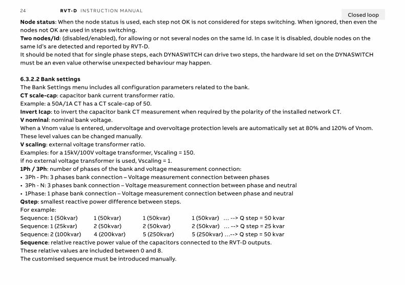
Node status: When the node status is used, each step not OK is not considered for steps switching. When ignored, then even the nodes not OK are used in steps switching.Two nodes/Id: (disabled/enabled), for allowing or not several nodes on the same Id. In case it is disabled, double nodes on the same Id’s are detected and reported by RVT-D.It should be noted that for single phase steps, each DYNASWITCH can drive two steps, the hardware Id set on the DYNASWITCH must be an even value otherwise unexpected behaviour may happen.
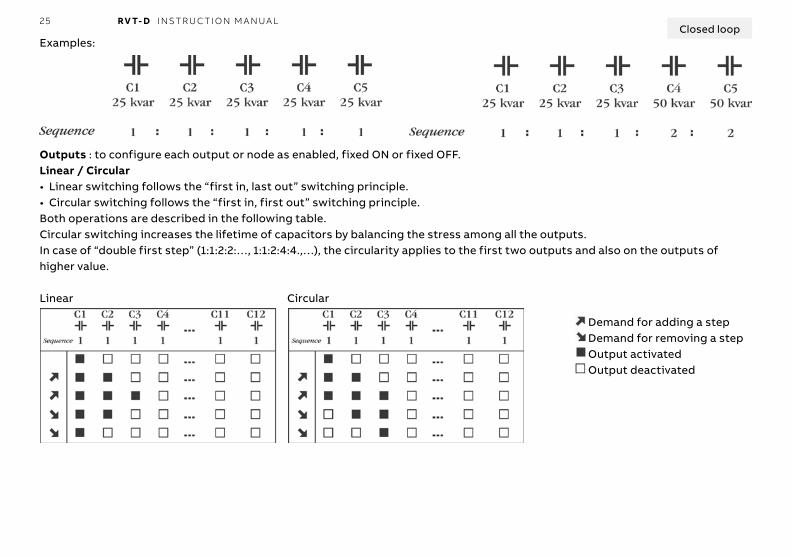
6.3.2.2 Bank settingsThe Bank Settings menu includes all configuration parameters related to the bank.CT scale-cap: capacitor bank current transformer ratio.Example: a 50A/1A CT has a CT scale-cap of 50.Invert Icap: to invert the capacitor bank CT measurement when required by the polarity of the installed network CT.V nominal: nominal bank voltage.When a Vnom value is entered, undervoltage and overvoltage protection levels are automatically set at 80% and 120% of Vnom.These level values can be changed manually.V scaling: external voltage transformer ratio.Examples: for a 15kV/100V voltage transformer, Vscaling = 150.if no external voltage transformer is used, Vscaling = 1.1Ph / 3Ph: number of phases of the bank and voltage measurement connection:• 3Ph - Ph: 3 phases bank connection – Voltage measurement connection between phases• 3Ph - N: 3 phases bank connection – Voltage measurement connection between phase and neutral• 1Phase: 1 phase bank connection – Voltage measurement connection between phase and neutralQstep: smallest reactive power difference between steps.For example: Sequence: 1 (50kvar) 1 (50kvar) 1 (50kvar) 1 (50kvar) … --> Q step = 50 kvarSequence: 1 (25kvar) 2 (50kvar) 2 (50kvar) 2 (50kvar) … --> Q step = 25 kvarSequence: 2 (100kvar) 4 (200kvar) 5 (250kvar) 5 (250kvar) …--> Q step = 50 kvarSequence: relative reactive power value of the capacitors connected to the RVT-D outputs.These relative values are included between 0 and 8.The customised sequence must be introduced manually.
Closed loop
25 RV T- D I NS TR U C TI O N M A N UA L
Examples:
Outputs : to configure each output or node as enabled, fixed ON or fixed OFF.Linear / Circular• Linear switching follows the “first in, last out” switching principle.• Circular switching follows the “first in, first out” switching principle.Both operations are described in the following table.Circular switching increases the lifetime of capacitors by balancing the stress among all the outputs.In case of “double first step” (1:1:2:2:…, 1:1:2:4:4.,…), the circularity applies to the first two outputs and also on the outputs of higher value.
Linear Circular
Demand for adding a stepDemand for removing a stepOutput activatedOutput deactivated
Closed loop
26 RV T- D I NS TR U C TI O N M A N UA L
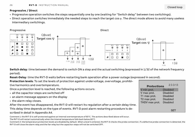
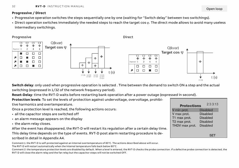
Progressive / Direct• Progressive operation switches the steps sequentially one by one (waiting for “Switch delay” between two switchings).• Direct operation switches immediately the needed steps to reach the target cos ϕ. The direct mode allows to avoid many useless
intermediary switchings.
Progressive Direct
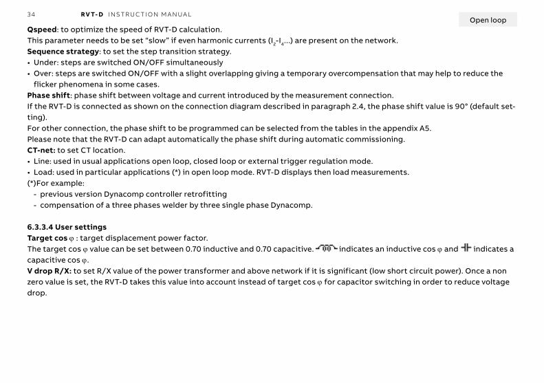
Switch delay: time between the demand to switch ON a step and the actual switching (expressed in 1/32 of the network frequency period).Reset-Delay: time the RVT-D waits before restarting bank operation after a power outage (expressed in second).Protection levels: To set the levels of protection against undervoltage, overvoltage, prohibi-tive harmonics and overtemperature.Once a protection level is reached, the following actions occurs:• all the capacitor steps are switched off• an alarm message appears on the display• the alarm relay closes.After the event has disappeared, the RVT-D will restart its regulation after a certain delay time.This delay time depends on the type of events. RVT-D post alarm restarting procedure is de-scribed in detail in Appendix A4.Comment 1: the RVT-D is self-protected against an internal overtemperature of 85°C. The actions described above will occur.The RVT-D will restart automatically when the intemal temperature falls back below 80°C.Comment 2: the temperature protection levels are disabled by default. When a level is entered, the RVT-D checks the probe connection. If a defective probe connection is detected, the RVT-D will close the alarm relay and the fan relay but the capacitor steps will not be switched OFF.
Closed loop
27 RV T- D I NS TR U C TI O N M A N UA L
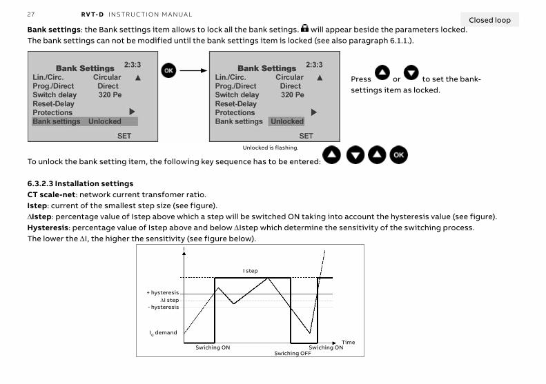
Bank settings: the Bank settings item allows to lock all the bank setings. will appear beside the parameters locked.The bank settings can not be modified until the bank settings item is locked (see also paragraph 6.1.1.).
Unlocked is flashing.
To unlock the bank setting item, the following key sequence has to be entered:
6.3.2.3 Installation settingsCT scale-net: network current transfomer ratio.Istep: current of the smallest step size (see figure).ΔIstep: percentage value of Istep above which a step will be switched ON taking into account the hysteresis value (see figure).Hysteresis: percentage value of Istep above and below ΔIstep which determine the sensitivity of the switching process.The lower the ΔI, the higher the sensitivity (see figure below).
Press or to set the bank-settings item as locked.
+ hysteresisΔI step
- hysteresis
IQ demand
Swiching ON Swiching ONSwiching OFF
I step
Time
I
Closed loop

28 RV T- D I NS TR U C TI O N M A N UA L
Qspeed: to optimize the speed of RVT-D calculation.This parameter needs to be set “slow” if even harmonic currents (I2-I4...) are present on the network.Sequence strategy: to set the step transition strategy.• Under: steps are switched ON/OFF simultaneously• Over: steps are switched ON/OFF with a slight overlapping giving a temporary overcompensation that may help to reduce the
flicker phenomena in some cases.Phase shift: phase shift between voltage and current introduced by the measurement connection.If the RVT-D is connected as shown on the connection diagram described in paragraph 2.4, the phase shift value is 90° (default set-ting).For other connection, the phase shift to be programmed can be selected from the tables in the appendix A5.Please note that the RVT-D can adapt automatically the phase shift during automatic commissioning.
6.3.2.4 User settingsTarget cos ϕ : target displacement power factor.The target cos ϕ value can be set between 0.70 inductive and 0.70 capacitive. indicates an inductive cos ϕ and indicates a capacitive cos ϕ.V drop R/X: to set R/X value of the power transformer and above network if it is significant (low short circuit power). Once a non zero value is set, the RVT-D takes this value into account instead of target cos ϕ for capacitor switching in order to reduce voltage drop.
Closed loop
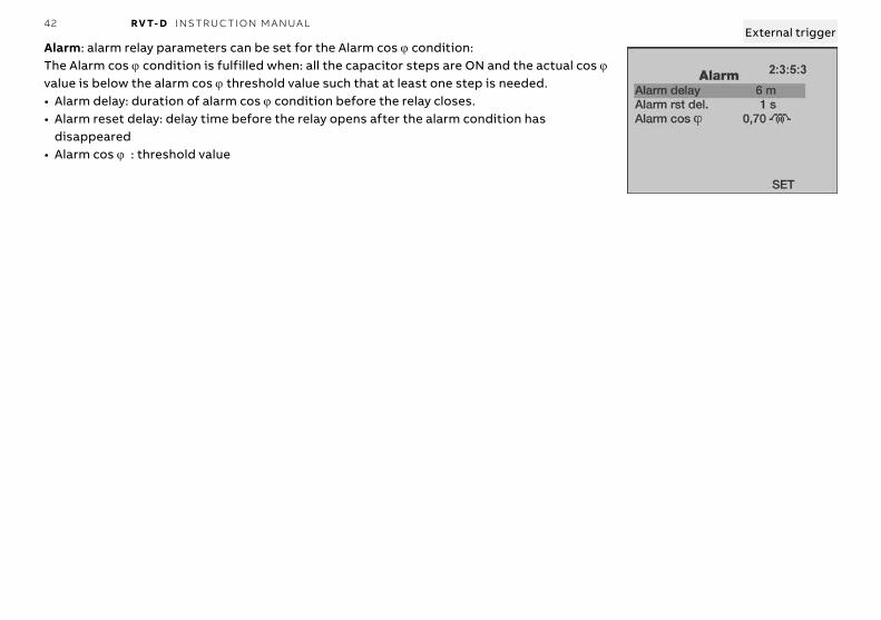
Alarm: alarm relay parameters can be set for the Alarm cos ϕ condition:In AUTO mode, the Alarm cos ϕ condition is fulfilled when: all the capacitor steps are ON and the actual cos ϕ value is below the alarm cos ϕ threshold value such that at least one step is needed.• Alarm delay: duration of alarm cos ϕ condition before the relay closes.• Alarm reset delay: delay time before the relay opens after the alarm condition has
disappeared• Alarm cos ϕ : threshold value

29 RV T- D I NS TR U C TI O N M A N UA L
6.3.3 Control: open loop6.3.3.1 CANThe CAN menu allows to set and read the parameters related to the control of steps through CAN bus.CAN control: when enabled, both synchronisation and control of each steps are performed through CAN bus. Otherwise, the On/Off control is performed only through output transistors. When enabled, if any step declared valid in the sequence reports a non-ready status, an error message is displayedAny uncontrolled change of these parameters can cause erratic behavior or even destroy parts of the DYNASWITCH.The settings must be applied by experienced users.Node type: for characterising the type for load to be switched by the DYNASWITCH. This allows to switch 1Ph/3Ph loads as well as Capacitor/Reactor loads. For proper operation when switching reactors, please invert the CT measurement physically or by set-ting the “phase shift” accordingly. In this condition, the power (P & Q) measurements will be displayed with the opposite polarity than they are actually.Synchro advance: for tuning the phase advance of the synchronising signal compared with the zero-crossing rising edge of the voltage measured by RVT-D. It is expressed in PE/4, which means that 128 represent a whole fundamental period.Dead time: for tuning the duration while no Thyristor is fired between Thyristor transitions. It is expressed in degree.
Reporting “Missing” No node with this Id
Reporting “Ready” Node ready to switch
Reporting “Fuse err.” Thyristor over temperatureProtistor opening
Reporting "Sync. err." RVT-D sends inconsistent synchronizing signal
Reporting “Wire err.” When the AC voltage sensed across one of the switch is not compliant with type of load compared with the top synchroreceived from RVT-D. This protects against wrong cabling of Gates / Power / RVT-D.
Reporting “Rst del.” The DYNASWITCH is in the reset phase after an initialisation.
Reporting “Discharg.” If the DC voltage sensed on the switch after the reset delay is still higher than 100V, then the switch waits until it is below100V before switching ON. In case of total failure of the discharge resistors, then it will prevent the DYNASWITCH to switch.
Reporting “Disc. War.” When the DC voltage sensed across one of the switch depicts a problem in the discharge resistors, it reports a warning,but the switching goes on (but starting with proper phase).
Reporting “Multiple” When at least two nodes have the same Id and it is not allowed (“Two nodes/Id” disabled).
Nodes overview: gives for all declared nodes in the RVT-D the status.The below lists the different status reported by RVT-D about DYNASWITCH (one status per node Id):
Open loop
30 RV T- D I NS TR U C TI O N M A N UA L
Node status: When the node status is used, each step not OK is not considered for steps switching. When ignored, then even the nodes not OK are used in steps switching.Two nodes/Id: (disabled/enabled), for allowing or not several nodes on the same Id. In case it is disabled, double nodes on the same Id’s are detected and reported by RVT-D.It should be noted that for single phase steps, each DYNASWITCH can drive two steps, the hardware Id set on the DYNASWITCH must be an even value otherwise unexpected behaviour may happen.
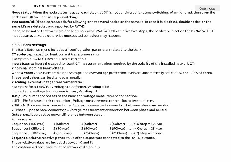
6.3.3.2 Bank settingsThe Bank Settings menu includes all configuration parameters related to the bank.CT scale-cap: capacitor bank current transformer ratio.Example: a 50A/1A CT has a CT scale-cap of 50.Invert Icap: to invert the capacitor bank CT measurement when required by the polarity of the installed network CT.V nominal: nominal bank voltage.When a Vnom value is entered, undervoltage and overvoltage protection levels are automatically set at 80% and 120% of Vnom.These level values can be changed manually.V scaling: external voltage transformer ratio.Examples: for a 15kV/100V voltage transformer, Vscaling = 150.if no external voltage transformer is used, Vscaling = 1.1Ph / 3Ph: number of phases of the bank and voltage measurement connection:• 3Ph - Ph: 3 phases bank connection – Voltage measurement connection between phases• 3Ph - N: 3 phases bank connection – Voltage measurement connection between phase and neutral• 1Phase: 1 phase bank connection – Voltage measurement connection between phase and neutralQstep: smallest reactive power difference between steps.For example: Sequence: 1 (50kvar) 1 (50kvar) 1 (50kvar) 1 (50kvar) … --> Q step = 50 kvarSequence: 1 (25kvar) 2 (50kvar) 2 (50kvar) 2 (50kvar) … --> Q step = 25 kvarSequence: 2 (100kvar) 4 (200kvar) 5 (250kvar) 5 (250kvar) …--> Q step = 50 kvarSequence: relative reactive power value of the capacitors connected to the RVT-D outputs.These relative values are included between 0 and 8.The customised sequence must be introduced manually.
Open loop

31 RV T- D I NS TR U C TI O N M A N UA L
Examples:
Outputs : to configure each output or node as enabled, fixed ON or fixed OFF.Linear / Circular• Linear switching follows the “first in, last out” switching principle.• Circular switching follows the “first in, first out” switching principle.Both operations are described in the following table.Circular switching increases the lifetime of capacitors by balancing the stress among all the outputs.In case of “double first step” (1:1:2:2:…, 1:1:2:4:4.,…), the circularity applies to the first two outputs and also on the outputs of higher value.
Linear Circular
Demand for adding a stepDemand for removing a stepOutput activatedOutput deactivated
Open loop
32 RV T- D I NS TR U C TI O N M A N UA L
Progressive / Direct• Progressive operation switches the steps sequentially one by one (waiting for “Switch delay” between two switchings).• Direct operation switches immediately the needed steps to reach the target cos ϕ. The direct mode allows to avoid many useless
intermediary switchings.
Progressive Direct
Switch delay: only used when progressive operation is selected . Time between the demand to switch ON a step and the actual switching (expressed in 1/32 of the network frequency period).Reset-Delay: time the RVT-D waits before restarting bank operation after a power outage (expressed in second).Protection levels: To set the levels of protection against undervoltage, overvoltage, prohibi-tive harmonics and overtemperature.Once a protection level is reached, the following actions occurs:• all the capacitor steps are switched off• an alarm message appears on the display• the alarm relay closes.After the event has disappeared, the RVT-D will restart its regulation after a certain delay time.This delay time depends on the type of events. RVT-D post alarm restarting procedure is de-scribed in detail in Appendix A4.Comment 1: the RVT-D is self-protected against an internal overtemperature of 85°C. The actions described above will occur.The RVT-D will restart automatically when the intemal temperature falls back below 80°C.Comment 2: the temperature protection levels are disabled by default. When a level is entered, the RVT-D checks the probe connection. If a defective probe connection is detected, the RVT-D will close the alarm relay and the fan relay but the capacitor steps will not be switched OFF.
Open loop

33 RV T- D I NS TR U C TI O N M A N UA L
Bank settings: the Bank settings item allows to lock all the bank setings. will appear beside the parameters locked.The bank settings can not be modified until the bank settings item is locked (see also paragraph 6.1.1.).
Unlocked is flashing.
To unlock the bank setting item, the following key sequence has to be entered:
6.3.3.3 Installation settingsCT scale-net: network current transfomer ratio.Istep: current of the smallest step size (see figure here below).ΔIstep: percentage value of Istep above which a step will be switched ON taking into account the hysteresis value (see figure).Hysteresis: percentage value of Istep above and below ΔIstep which determine the sensitivity of the switching process.The lower the ΔI, the higher the sensitivity (see figure below).
Press or to set the bank-settings item as locked.
+ hysteresisΔI step
- hysteresis
IQ demand
Swiching ON Swiching ONSwiching OFF
I step
Time
I
Open loop
34 RV T- D I NS TR U C TI O N M A N UA L
Qspeed: to optimize the speed of RVT-D calculation.This parameter needs to be set “slow” if even harmonic currents (I2-I4...) are present on the network.Sequence strategy: to set the step transition strategy.• Under: steps are switched ON/OFF simultaneously• Over: steps are switched ON/OFF with a slight overlapping giving a temporary overcompensation that may help to reduce the
flicker phenomena in some cases.Phase shift: phase shift between voltage and current introduced by the measurement connection.If the RVT-D is connected as shown on the connection diagram described in paragraph 2.4, the phase shift value is 90° (default set-ting).For other connection, the phase shift to be programmed can be selected from the tables in the appendix A5.Please note that the RVT-D can adapt automatically the phase shift during automatic commissioning.CT-net: to set CT location.• Line: used in usual applications open loop, closed loop or external trigger regulation mode.• Load: used in particular applications (*) in open loop mode. RVT-D displays then load measurements.(*)For example:
- previous version Dynacomp controller retrofitting - compensation of a three phases welder by three single phase Dynacomp.
6.3.3.4 User settingsTarget cos ϕ : target displacement power factor.The target cos ϕ value can be set between 0.70 inductive and 0.70 capacitive. indicates an inductive cos ϕ and indicates a capacitive cos ϕ.V drop R/X: to set R/X value of the power transformer and above network if it is significant (low short circuit power). Once a non zero value is set, the RVT-D takes this value into account instead of target cos ϕ for capacitor switching in order to reduce voltage drop.
Open loop

35 RV T- D I NS TR U C TI O N M A N UA LOpen loop
Alarm: alarm relay parameters can be set for the Alarm cos ϕ condition:The Alarm cos ϕ condition is fulfilled when: all the capacitor steps are ON and the actual cos ϕ value is below the alarm cos ϕ threshold value such that at least one step is needed.• Alarm delay: duration of alarm cos ϕ condition before the relay closes.• Alarm reset delay: delay time before the relay opens after the alarm condition has
disappeared• Alarm cos ϕ : threshold value
6.3.4 Control: external trigger6.3.4.1 CANThe CAN menu allows to set and read the parameters related to the control of steps through CAN bus.CAN control: when enabled, both synchronisation and control of each steps are performed through CAN bus. Otherwise, only the On/Off control is performed through output transistors. When enabled, if any step declared valid in the sequence reports a non-ready status, an error message is displayed
External trigger
Any uncontrolled change of these parameters can cause erratic behavior or even destroy parts of the DYNASWITCH.The settings must be applied by experienced users.Node type: for characterising the type for load to be switched by the DYNASWITCH. This allows to switch 1Ph/3Ph loads as well as Capacitor/Reactor loads. For proper operation when switching reactors, please invert the CT measurement physically or by set-ting the “phase shift” accordingly. In this condition, the power (P & Q) measurements will be displayed with the opposite polarity than they are actually.Synchro advance: for tuning the phase advance of the synchronising signal compared with the zero-crossing rising edge of the voltage measured by RVT-D. It is expressed in PE/4, which means that 128 represent a whole fundamental period.Dead time: for tuning the duration while no Thyristor is fired between Thyristor transitions. It is expressed in degree.

36 RV T- D I NS TR U C TI O N M A N UA L
Reporting “Missing” No node with this Id
Reporting “Ready” Node ready to switch
Reporting “Fuse err.” Thyristor over temperatureProtistor opening
Reporting "Sync. err." RVT-D sends inconsistent synchronizing signal
Reporting “Wire err.” When the AC voltage sensed across one of the switch is not compliant with type of load compared with the top synchroreceived from RVT-D. This protects against wrong cabling of Gates / Power / RVT-D.
Reporting “Rst del.” The DYNASWITCH is in the reset phase after an initialisation.
Reporting “Discharg.” If the DC voltage sensed on the switch after the reset delay is still higher than 100V, then the switch waits until it is below100V before switching ON. In case of total failure of the discharge resistors, then it will prevent the DYNASWITCH to switch.
Reporting “Disc. War.” When the DC voltage sensed across one of the switch depicts a problem in the discharge resistors, it reports a warning,but the switching goes on (but starting with proper phase).
Reporting “Multiple” When at least two nodes have the same Id and it is not allowed (“Two nodes/Id” disabled).
Nodes overview: gives for all declared nodes in the RVT-D the status.The below lists the different status reported by RVT-D about DYNASWITCH (one status per node Id):
External trigger
Node status: When the node status is used, each step not OK is not considered for steps switching. When ignored, then even the nodes not OK are used in steps switching.Two nodes/Id: (disabled/enabled), for allowing or not several nodes on the same Id. In case it is disabled, double nodes on the same Id’s are detected and reported by RVT-D.It should be noted that for single phase steps, each DYNASWITCH can drive two steps, the hardware Id set on the DYNASWITCH must be an even value otherwise unexpected behaviour may happen.
6.3.4.2 Bank settingsThe Bank Settings menu includes all configuration parameters related to the bank.CT scale-cap: capacitor bank current transformer ratio.Example: a 50A/1A CT has a CT scale-cap of 50.Invert Icap: to invert the capacitor bank CT measurement when required by the polarity of the installed network CT.V nominal: nominal bank voltage.When a Vnom value is entered, undervoltage and overvoltage protection levels are automatically set at 80% and 120% of Vnom.These level values can be changed manually.

37 RV T- D I NS TR U C TI O N M A N UA LExternal trigger
V scaling: external voltage transformer ratio.Examples: for a 15kV/100V voltage transformer, Vscaling = 150.if no external voltage transformer is used, Vscaling = 1.1Ph / 3Ph: number of phases of the bank and voltage measurement connection:• 3Ph - Ph: 3 phases bank connection – Voltage measurement connection between phases• 3Ph - N: 3 phases bank connection – Voltage measurement connection between phase and neutral• 1Phase: 1 phase bank connection – Voltage measurement connection between phase and neutralQstep: smallest reactive power difference between steps.For example: Sequence: 1 (50kvar) 1 (50kvar) 1 (50kvar) 1 (50kvar) … --> Q step = 50 kvarSequence: 1 (25kvar) 2 (50kvar) 2 (50kvar) 2 (50kvar) … --> Q step = 25 kvarSequence: 2 (100kvar) 4 (200kvar) 5 (250kvar) 5 (250kvar) …--> Q step = 50 kvarSequence: relative reactive power value of the capacitors connected to the RVT-D outputs.These relative values are included between 0 and 8.The customised sequence must be introduced manually.Examples:
Outputs : to configure each output or node as enabled, fixed ON or fixed OFF.Linear / Circular• Linear switching follows the “first in, last out” switching principle.• Circular switching follows the “first in, first out” switching principle.Both operations are described in the following table.Circular switching increases the lifetime of capacitors by balancing the stress among all the outputs.In case of “double first step” (1:1:2:2:…, 1:1:2:4:4.,…), the circularity applies to the first two outputs and also on the outputs of higher value.

38 RV T- D I NS TR U C TI O N M A N UA LExternal trigger
Linear Circular
Demand for adding a stepDemand for removing a stepOutput activatedOutput deactivated
Progressive / Direct• Progressive operation switches the steps sequentially one by one (waiting for “Switch delay” between two switchings).• Direct operation switches immediately the needed steps to reach the target cos ϕ. The direct mode allows to avoid many useless
intermediary switchings.
Progressive Direct
Switch delay: only used when progressive operation is selected . Time between the demand to switch ON a step and the actual switching (expressed in 1/32 of the network frequency period).Reset-Delay: time the RVT-D waits before restarting bank operation after a power outage (expressed in second).

39 RV T- D I NS TR U C TI O N M A N UA LExternal trigger
Protection levels: To set the levels of protection against undervoltage, overvoltage, prohibi-tive harmonics and overtemperature.Once a protection level is reached, the following actions occurs:• all the capacitor steps are switched off• an alarm message appears on the display• the alarm relay closes.After the event has disappeared, the RVT-D will restart its regulation after a certain delay time.This delay time depends on the type of events. RVT-D post alarm restarting procedure is de-scribed in detail in Appendix A4.Comment 1: the RVT-D is self-protected against an internal overtemperature of 85°C. The actions described above will occur.The RVT-D will restart automatically when the intemal temperature falls back below 80°C.Comment 2: the temperature protection levels are disabled by default. When a level is entered, the RVT-D checks the probe connection. If a defective probe connection is detected, the RVT-D will close the alarm relay and the fan relay but the capacitor steps will not be switched OFF.
Bank settings: the Bank settings item allows to lock all the bank setings. will appear beside the parameters locked.The bank settings can not be modified until the bank settings item is locked (see also paragraph 6.1.1.).
Unlocked is flashing.
To unlock the bank setting item, the following key sequence has to be entered:
Press or to set the bank-settings item as locked.
40 RV T- D I NS TR U C TI O N M A N UA LExternal trigger
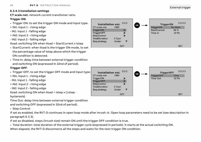
6.3.4.3 Installation settingsCT scale-net: network current transfomer ratio.Trigger ON:• Trigger ON: to set the trigger ON mode and input type:+ IN1: input 1 - rising edge- IN1: input 1 - falling edge+ IN2: input 2 - rising edge- IN2: input 2 - falling edgeIload: switching ON when Iload > StartCurrent x Istep• StartCurrent: when Iload is the trigger ON mode, to set
the percentage value of Istep above which the trigger ON condition is detected.
• Time In: delay time between external trigger condition and switching ON (expressed in 32nd of period).
Trigger OFF:• Trigger OFF: to set the trigger OFF mode and input type:+ IN1: input 1 - rising edge- IN1: input 1 - falling edge+ IN2: input 2 - rising edge- IN2: input 2 - falling edgeIload: switching ON when Iload < Istep x (Δstep - hysteresis)Time Out: delay time between external trigger condition and switching OFF (expressed in 32nd of period).• Step Control:If set as enabled, the RVT-D continues in open loop mode after Inrush Δt. Open loop parameters need to be set (see description in paragraph 6.3.3).If set as disabled, steps (Inrush size) remain ON until the trigger OFF condition is true.• Total duration: total duration of the external trigger cycle (expressed in periods). It starts at the actual switching ON.When elapsed, the RVT-D disconnects all the steps and waits for the next trigger ON condition.
41 RV T- D I NS TR U C TI O N M A N UA L
Sequence strategy: to set the step transition strategy.• Under: steps are switched ON/OFF simultaneously• Over: steps are switched ON/OFF with a slight overlapping giving a temporary overcompensation that may help to reduce the
flicker phenomena in some cases.Phase shift: phase shift between voltage and current introduced by the measurement connection.If the RVT-D is connected as shown on the connection diagram described in paragraph 2.4, the phase shift value is 90° (default set-ting).For other connection, the phase shift to be programmed can be selected from the tables in the appendix A5.Please note that the RVT-D can adapt automatically the phase shift during automatic commissioning.CT-net: to set CT location.• Line: used in usual applications open loop, closed loop or external trigger regulation mode.• Load: used in particular applications (*) in open loop mode. RVT-D displays then load measurements.(*)For example:
- previous version Dynacomp controller retrofitting - compensation of a three phases welder by three single phase Dynacomp.
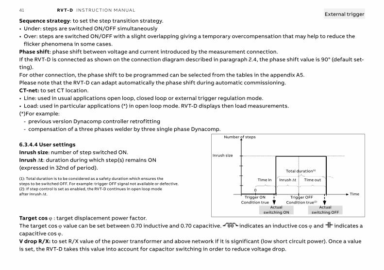
6.3.4.4 User settingsInrush size: number of step switched ON.Inrush Δt: duration during which step(s) remains ON (expressed in 32nd of period).
(1): Total duration is to be considered as a safety duration which ensures the steps to be switched OFF. For example: trigger OFF signal not available or defective.(2): If step control is set as enabled, the RVT-D continues in open loop mode after Inrush Δt.
Target cos ϕ : target displacement power factor.The target cos ϕ value can be set between 0.70 inductive and 0.70 capacitive. indicates an inductive cos ϕ and indicates a capacitive cos ϕ.V drop R/X: to set R/X value of the power transformer and above network if it is significant (low short circuit power). Once a value is set, the RVT-D takes this value into account for capacitor switching in order to reduce voltage drop.
External trigger
Inrush size
Trigger ONCondition true
Total duration(1)
Time
Number of steps
Time In Inrush Δt Time out
Trigger OFFCondition true(2)
Actual switching ON
Actual switching OFF
0
42 RV T- D I NS TR U C TI O N M A N UA L
Alarm: alarm relay parameters can be set for the Alarm cos ϕ condition:The Alarm cos ϕ condition is fulfilled when: all the capacitor steps are ON and the actual cos ϕ value is below the alarm cos ϕ threshold value such that at least one step is needed.• Alarm delay: duration of alarm cos ϕ condition before the relay closes.• Alarm reset delay: delay time before the relay opens after the alarm condition has
disappeared• Alarm cos ϕ : threshold value
External trigger

43 RV T- D I NS TR U C TI O N M A N UA LExternal trigger
Global overview of external trigger parameters
Standby
TriggerON cond.
TriggerON expired
Switch ON - Inrush size
Start open loop operation
Inrush Δt expired
Step control enabled
TriggerOFF cond.
TriggerOFF expired
Switch OFF all steps
Standby
All steps disconnected
Y
Y
Y
Y
Y
Y
N
N
N
N
N
N
TriggerON (by ext. trigger or current)StartCurrent
All steps disconnected
Time In
Inrush size
Inrush Δt
StepControl
TriggerOFF
Time Out
44 RV T- D I NS TR U C TI O N M A N UA L
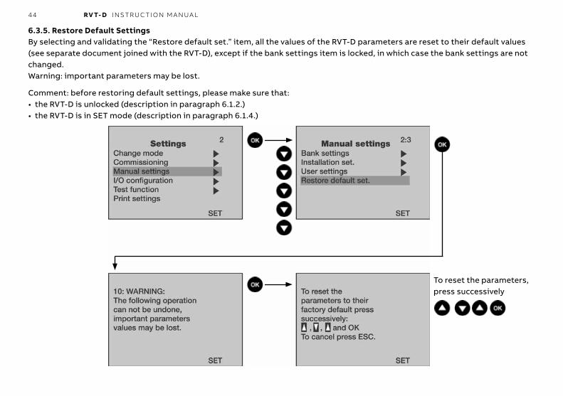
6.3.5. Restore Default SettingsBy selecting and validating the “Restore default set.” item, all the values of the RVT-D parameters are reset to their default values (see separate document joined with the RVT-D), except if the bank settings item is locked, in which case the bank settings are not changed.Warning: important parameters may be lost.
Comment: before restoring default settings, please make sure that:• the RVT-D is unlocked (description in paragraph 6.1.2.)• the RVT-D is in SET mode (description in paragraph 6.1.4.)
To reset the parameters, press successively

45 RV T- D I NS TR U C TI O N M A N UA L
6.4. Input / Output Configuration6.4.1. Various configurationThe I/O Configuration menu gives access to RVT-D parameters related to external communication and the graphic display.Before performing a parameter setting, please make sure that the RVT-D is unlocked (description in paragraph 6.1.1).
Temp unit: to select the temperature unit between degrees Celsius (°C) and degrees Farenheit (°F).Contrast: to adjust the contrast of the display (by +1 or –1 from the value indicated on the graphic display).Communication: to set the parameters relating to the serial communication link (this RVT-D version can be linked with a printer. For more information,please consult your ABB representative).
6.4.2. Communication (Printer or Modbus)The Communication menu gives access to RVT-D communication protocol (“Printer” or “Modbus”) and related parameters.

46 RV T- D I NS TR U C TI O N M A N UA L
Printer protocol: by selecting and validating the “Printer” protocol item, the RVT-D can communicate with a printer (DPU414 type - Seiko) by means of the ABB printer cable (optional). Parameters settings or measurements can be printed (description in para-graph 4.1.5 and 4.2.6).Modbus protocol: by selecting and validating the “Modbus” protocol item, the RVT-D can communicate in a Modbus supervision system. All RVT-D parameters as well as the RVT-D measurements are accessible (a comprehensive RVT-D Modbus instruction man-ual is provided separately).
Baud rate: to adjust the communication speed (bits/second).Parity: to set the parity checking.Stop bit: to set the number of stop bit(s).Slave address: to adjust the address of the Modbus/RTU slave. The Modbus master will refer to this address for each query / an-swer transaction with this RVT-D.Modbus lock: the “Modbus lock” item allows to lock the parameters access through the RVT-D padlock.Parameters then can only be modified with the Modbus communication.

47 RV T- D I NS TR U C TI O N M A N UA L
6.5. Test functionThe Test function menu allows the user to test each output of the RVT-D.Before proceeding the test functions, please make sure that:• the RVT-D is unlocked (description in paragraph 6.1.1.)• the RVT-D is in SET Mode (description in paragraph 6.1.4.)
Test alarm: allows testing of the alarm relay
or
48 RV T- D I NS TR U C TI O N M A N UA L
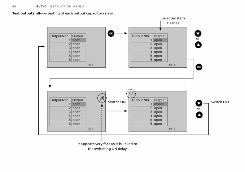
Test outputs: allows testing of each output capacitor relaysSelected item
flashes
Switch ON
or
or
Switch OFF
It appears very fast as it is linked to the switching ON delay
49 RV T- D I NS TR U C TI O N M A N UA L
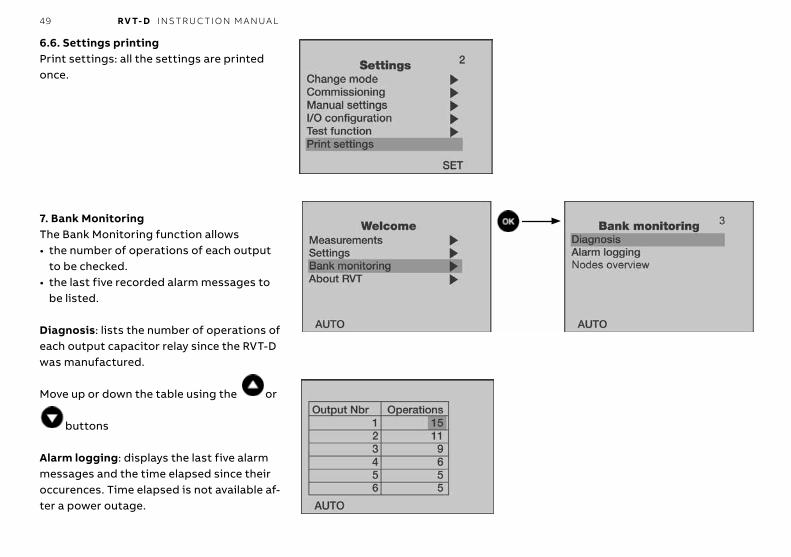
6.6. Settings printingPrint settings: all the settings are printed once.
7. Bank MonitoringThe Bank Monitoring function allows• the number of operations of each output
to be checked.• the last five recorded alarm messages to
be listed.
Diagnosis: lists the number of operations of each output capacitor relay since the RVT-D was manufactured.
Move up or down the table using the or
buttons
Alarm logging: displays the last five alarm messages and the time elapsed since their occurences. Time elapsed is not available af-ter a power outage.
50 RV T- D I NS TR U C TI O N M A N UA L
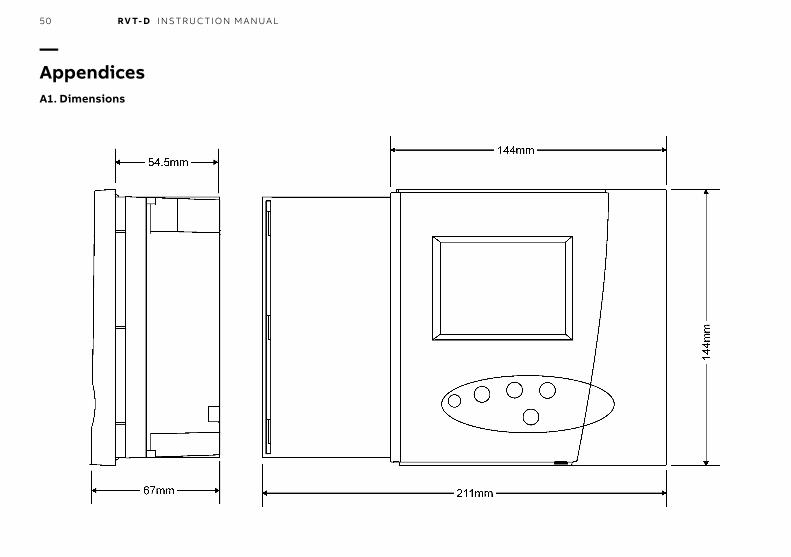
—AppendicesA1. Dimensions
51 RV T- D I NS TR U C TI O N M A N UA L
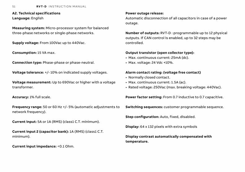
A2. Technical specificationsLanguage: English
Measuring system: Micro-processor system for balanced three-phase networks or single-phase networks.
Supply voltage: From 100Vac up to 440Vac.
Consumption: 15 VA max.
Connection type: Phase-phase or phase-neutral.
Voltage tolerance: +/- 10% on indicated supply voltages.
Voltage measurement: Up to 690Vac or higher with a voltage transformer.
Accuracy: 1% full scale.
Frequency range: 50 or 60 Hz +/- 5% (automatic adjustments to network frequency).
Current input: 5A or 1A (RMS) (class1 C.T. minimum).
Current input 2 (capacitor bank): 1A (RMS) (class1 C.T. minimum).
Current input impedance: <0.1 Ohm.
Power outage release:Automatic disconnection of all capacitors in case of a power outage.
Number of outputs: RVT-D : programmable up to 12 physical outputs. If CAN control is enabled, up to 32 steps may be controlled.
Output transistor (open collector type):• Max. continuous current: 25mA (dc).• Max. voltage: 24 Vdc +10%.
Alarm contact rating: (voltage free contact)• Normally closed contact.• Max. continuous current: 1.5A (ac).• Rated voltage: 250Vac (max. breaking voltage: 440Vac).
Power factor setting: From 0.7 inductive to 0.7 capacitive.
Switching sequences: customer programmable sequence.
Step configuration: Auto, fixed, disabled.
Display: 64 x 132 pixels with extra symbols
Display contrast automatically compensated with temperature.
52 RV T- D I NS TR U C TI O N M A N UA L
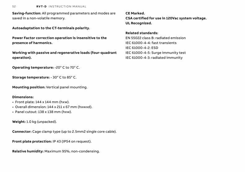
Saving-function: All programmed parameters and modes are saved in a non-volatile memory.
Autoadaptation to the CT-terminals polarity.
Power Factor correction operation is insensitive to the presence of harmonics.
Working with passive and regenerative loads (four-quadrant operation).
Operating temperature: -20° C to 70° C.
Storage temperature: - 30° C to 85° C.
Mounting position: Vertical panel mounting.
Dimensions:• Front plate: 144 x 144 mm (hxw).• Overall dimension: 144 x 211 x 67 mm (hxwxd).• Panel cutout: 138 x 138 mm (hxw).
Weight: 1.0 kg (unpacked).
Connector: Cage clamp type (up to 2.5mm2 single core cable).
Front plate protection: IP 43 (IP54 on request).
Relative humidity: Maximum 95%; non-condensing.
CE Marked.CSA certified for use in 120Vac system voltage.UL Recognized.
Related standards:EN 55022 class B: radiated emission IEC 61000-4-4: fast transientsIEC 61000-4-2: ESD IEC 61000-4-5: Surge immunity testIEC 61000-4-3: radiated immunity
53 RV T- D I NS TR U C TI O N M A N UA L
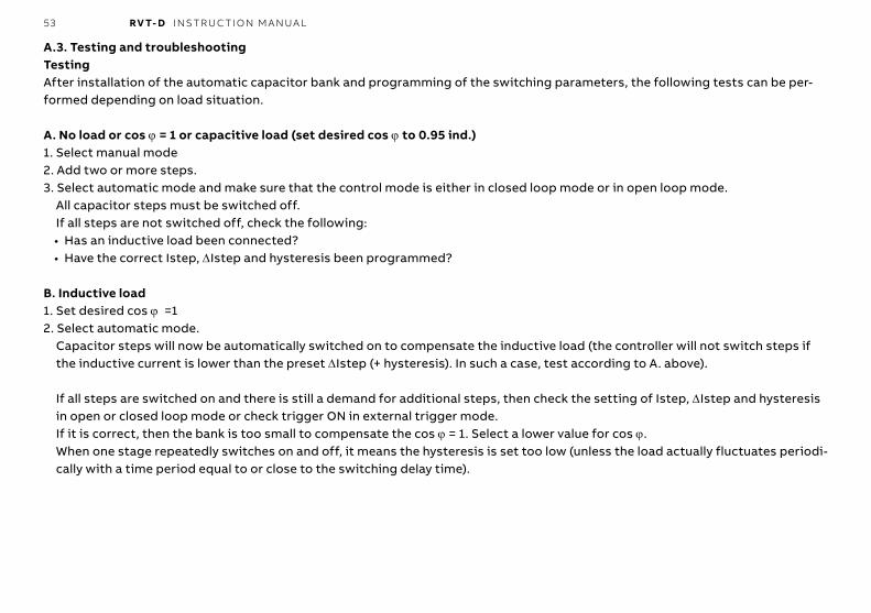
A.3. Testing and troubleshootingTestingAfter installation of the automatic capacitor bank and programming of the switching parameters, the following tests can be per-formed depending on load situation.
A. No load or cos ϕ = 1 or capacitive load (set desired cos ϕ to 0.95 ind.)1. Select manual mode2. Add two or more steps.3. Select automatic mode and make sure that the control mode is either in closed loop mode or in open loop mode.
All capacitor steps must be switched off.If all steps are not switched off, check the following:• Has an inductive load been connected?• Have the correct Istep, ΔIstep and hysteresis been programmed?
B. Inductive load1. Set desired cos ϕ =12. Select automatic mode.
Capacitor steps will now be automatically switched on to compensate the inductive load (the controller will not switch steps if the inductive current is lower than the preset ΔIstep (+ hysteresis). In such a case, test according to A. above).
If all steps are switched on and there is still a demand for additional steps, then check the setting of Istep, ΔIstep and hysteresis in open or closed loop mode or check trigger ON in external trigger mode.If it is correct, then the bank is too small to compensate the cos ϕ = 1. Select a lower value for cos ϕ.When one stage repeatedly switches on and off, it means the hysteresis is set too low (unless the load actually fluctuates periodi-cally with a time period equal to or close to the switching delay time).
54 RV T- D I NS TR U C TI O N M A N UA L
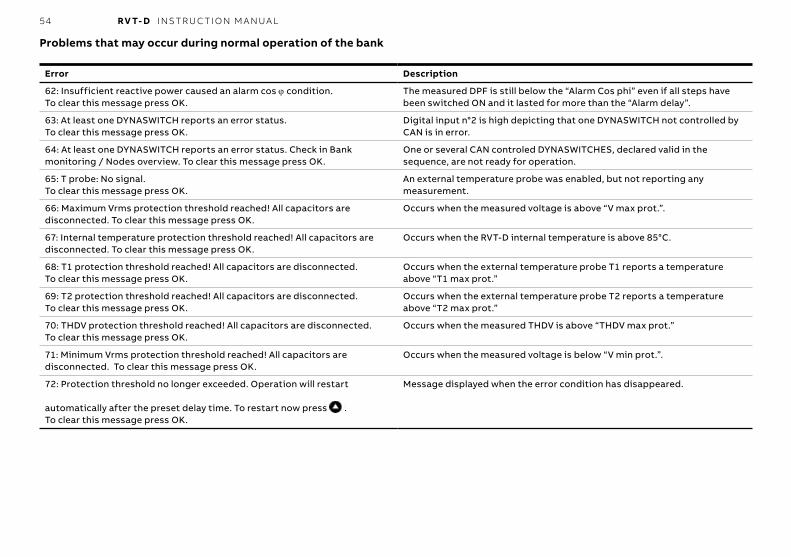
Problems that may occur during normal operation of the bank
Error Description
62: Insufficient reactive power caused an alarm cos ϕ condition. To clear this message press OK.
The measured DPF is still below the “Alarm Cos phi” even if all steps have been switched ON and it lasted for more than the “Alarm delay”.
63: At least one DYNASWITCH reports an error status. To clear this message press OK.
Digital input n°2 is high depicting that one DYNASWITCH not controlled by CAN is in error.
64: At least one DYNASWITCH reports an error status. Check in Bank monitoring / Nodes overview. To clear this message press OK.
One or several CAN controled DYNASWITCHES, declared valid in the sequence, are not ready for operation.
65: T probe: No signal. To clear this message press OK.
An external temperature probe was enabled, but not reporting any measurement.
66: Maximum Vrms protection threshold reached! All capacitors are disconnected. To clear this message press OK.
Occurs when the measured voltage is above “V max prot.”.
67: Internal temperature protection threshold reached! All capacitors are disconnected. To clear this message press OK.
Occurs when the RVT-D internal temperature is above 85°C.
68: T1 protection threshold reached! All capacitors are disconnected. To clear this message press OK.
Occurs when the external temperature probe T1 reports a temperature above “T1 max prot.”
69: T2 protection threshold reached! All capacitors are disconnected. To clear this message press OK.
Occurs when the external temperature probe T2 reports a temperature above “T2 max prot.”
70: THDV protection threshold reached! All capacitors are disconnected. To clear this message press OK.
Occurs when the measured THDV is above “THDV max prot.”
71: Minimum Vrms protection threshold reached! All capacitors are disconnected. To clear this message press OK.
Occurs when the measured voltage is below “V min prot.”.
72: Protection threshold no longer exceeded. Operation will restart
automatically after the preset delay time. To restart now press .To clear this message press OK.
Message displayed when the error condition has disappeared.
55 RV T- D I NS TR U C TI O N M A N UA L
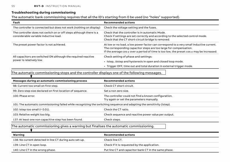
Troubleshooting during commissioningThe automatic bank commissining requires that all the ID’s starting from 0 be used (no “holes” supported).
Fault Recommended actions
The controller is connected but does not work (nothing on display) Check the voltage setting and the fuses.
The controller does not switch on or off steps although there is a considerable variable inductive load.
Check that the controller is in automatic Mode.Check if settings are set correctly and according to the selected control mode.Check that the CT short-circuit bridge is removed.
The preset power factor is not achieved. At low or no load, a low power factor can correspond to a very small inductive current. The corresponding capacitor steps are too large for compensation.If the average cos ϕ over a period of time is too low, the preset cos ϕ may be increased.
All capacitors are switched ON although the required reactive power is relatively low.
Check setting of phase and settings:
• Istep, ΔIstep and hysteresis in open and closed loop mode.
• Trigger OFF, time out and total duration in external trigger mode.
The automatic commissioning stops and the controller displays one of the following messages.
Messages during an automatic commissioning process Recommended actions
98: Current too small on first step. Check CT short circuit.
99: Zero step size declared on first location of sequence. Set a non zero size.
100: Phase error. The controller could not find a known configuration.Try again or set the parameters manually.
101: The automatic commissioning failed while recognizing the switching sequence and adapting the sensitivity (Istep).
102: Istep too small (< 0.01). Check the CT ratio.
103: Relative weight too big. Check sequence and reactive power value per output.
137: At least one non capacitive step has been found. Check steps.
The automatic commissioning gives a warning but finalises the automatic commissioning.
Warning Recommended actions
138: No current detected in line CT during auto set-up. Check line CT.
139: Line CT in open loop. Check if it is requested by the application.
140: Line CT in the wrong phase. Put line CT and capacitor bank CT in the same phase.

56 RV T- D I NS TR U C TI O N M A N UA L
A4. Post alarm restarting procedureOnce a protection level is reached (see paragraph 6.3.2) or when the internal temperature is higher than 85°C :• all the capacitor steps are switched off,• an alarm message appears on the LCD display,• the alarm relay closes.When the alarm condition disappears, the RVT-D will automatically restart.The restarting procedure will depend on the type of event that caused the alarm, as indicated in the following table:
Event having occured RVT-D restart behaviour after event has disappeared
Urms < Umin prot. Power outage
• Opens alarm relay immediately
• Resumes normal behaviour after a time equal to Reset-delay(*)
Urms > U max prot. • Opens alarm relay immediately
• Resumes normal behaviour after a time equal to Reset-Delay(*)
Tinternal > 85°C • Event considered as disappeared, when Tinternal < 80°C
• Opens alarm relay immediately
• Resumes normal behaviour after a time equal to Reset-Delay(*)
T1 > T1 max. prot. (external optional probe T1) • Opens alarm relay immediately
• Resumes normal behaviour after a time equal to Reset-Delay(*)
T2 > T2 max. prot. (external optional probe T2) • Opens alarm relay immediately.
• Resumes normal behaviour after a time equal to Rese-Delay(*)
THDV > THDV max prot. • Opens alarm relay immediately. • Resumes normal behaviour after a time equal to Reset-Delay(*).Anti-hunting protection:If the same event occurs within one hour, the RVT-D will resume normal operation after a time equal to 2x Reset-Delay.If the same event occurs again within one hour, the restart time will be doubled to 4 x Reset-Delay, and so on up to a maximum of one hour.This rule allows a hunting effect due to resonance phenomena to be avoided.
(*) For more information regarding the Reset-Delay parameter, a complete description is available in paragraph 6.3.2.

57 RV T- D I NS TR U C TI O N M A N UA L
A5. Check in case of maloperation of RVT-DSince no parts are serviceable in the RVT-D, it is important to know when it must be replaced. This is the purpose of this appendix.Connection checkBefore incriminating the RVT-D, some connection checks must be conduced. If one of the following requirements fails then the Dynacomp® problem does not come from the RVT-D (please refer to the Dynacomp® troubleshooting manual.)InputPower supply: is there at least 200Vac between pin PL2 and PL3 (200V-440V) or at least 100Vac between PL2 and PL3 (100V-200V) ?Voltage measurement: is the voltage applied between ML2 and ML3 a proper image of the line voltage (the same or with the proper scaling factor) ?Current measurement: is the current applied between k and I a proper image of the line current (with the proper scaling factor) ?External trigger: when used, with an oscilloscope, check that the voltage waveform applied on the corresponding input (Opto1 or/and Opto2) has the proper polarity and level. If one voltage is in the range of zero, please disconnect the wire from the RVT-D.OutputWhen all outputs are off (in MAN mode), the DC voltage between terminal A and the outputs used must be in the range of 15Vdc. If one volt-age is in the range of zero, please disconnect the corresponding output from the RVT-D connector and check the voltage on the wire. If the voltage is OK then this RVT-D output is dead, otherwise refer to the Dynacomp® troubleshooting manual.RVT-D checkIf all the above checks are OK, the RVT-D must be step by step checked as follows:
Step Comment
Power supply LCD display running ?
Measurement channels The measurements of Urms, frequency, I Line/Load and cos ϕ by RVT-D and on the line are similar ?
I capa measurement In MAN mode, switch ON one step. Does the I capa indication on the RVT-D follow the I capa measured ?
Output transistors With the test function in SET mode, switch each outupt successively and check if the voltage between the output pin and terminal A follows this switching (from about 15Vdc to about 0Vdc).
External trigger input If the external trigger is used (Control = Trigger) then set the parameters as follows:• Trigger ON = rising edge of the external trigger input to be tested• Trigger OFF = time• Inrush Δt = 2000Pe• Inrush size = 1
• Total duraction = 100 cyclesThen check on the LCD that at each rising edge of the external trigger, a step is switched.
Settings The settings are wrong, so the RVT-D does not have to be replaced, but a parameters setup must be conduced.
58 RV T- D I NS TR U C TI O N M A N UA L
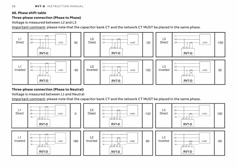
A6. Phase shift tableThree-phase connection (Phase to Phase)Voltage is measured between L2 and L3Important comment: please note that the capacitor bank CT and the network CT MUST be placed in the same phase.
Three-phase connection (Phase to Neutral)Voltage is measured between L1 and NeutralImportant comment: please note that the capacitor bank CT and the network CT MUST be placed in the same phase.
59 RV T- D I NS TR U C TI O N M A N UA L
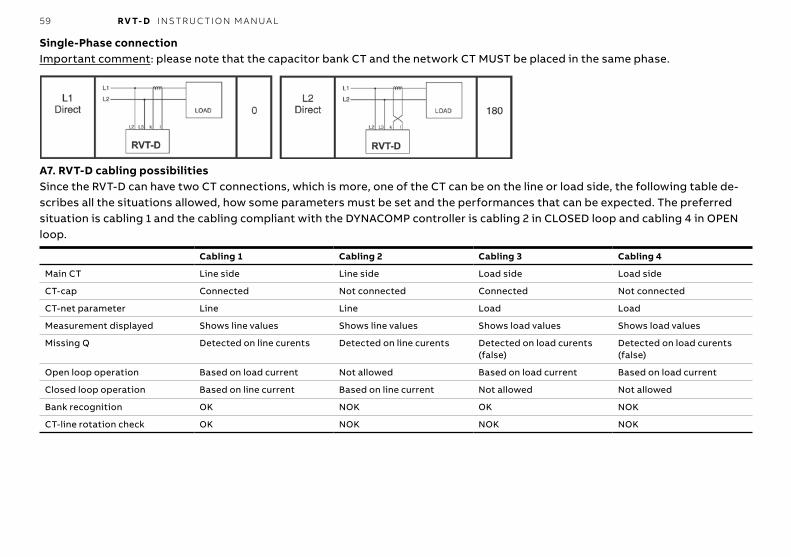
Single-Phase connectionImportant comment: please note that the capacitor bank CT and the network CT MUST be placed in the same phase.
A7. RVT-D cabling possibilitiesSince the RVT-D can have two CT connections, which is more, one of the CT can be on the line or load side, the following table de-scribes all the situations allowed, how some parameters must be set and the performances that can be expected. The preferred situation is cabling 1 and the cabling compliant with the DYNACOMP controller is cabling 2 in CLOSED loop and cabling 4 in OPEN loop.
Cabling 1 Cabling 2 Cabling 3 Cabling 4
Main CT Line side Line side Load side Load side
CT-cap Connected Not connected Connected Not connected
CT-net parameter Line Line Load Load
Measurement displayed Shows line values Shows line values Shows load values Shows load values
Missing Q Detected on line curents Detected on line curents Detected on load curents (false)
Detected on load curents (false)
Open loop operation Based on load current Not allowed Based on load current Based on load current
Closed loop operation Based on line current Based on line current Not allowed Not allowed
Bank recognition OK NOK OK NOK
CT-line rotation check OK NOK NOK NOK
60 RV T- D I NS TR U C TI O N M A N UA L
A8. Voltage measurement and power supply connectionThis appendix provides a practical way to connect voltage measurement to the RVT-D when it is the same as the RVT-D voltage supply.DescriptionAs shown on figure 1, the RVT-D has three terminals for its power supply and two other terminals for its voltage measurement input.The RVT-D does not use its power supply voltage to perform the voltage measurement. Voltage measurement is performed only through the dedicated voltage measurement input terminals.If the RVT-D auxiliary power supply and the voltage measurement signal are from the same source, a bridge between the corre-sponding terminals can be done (fig.2):
Figure 1 Figure 2
Voltage supplyfrom 200Vac up to 440Vac
ML3 ML2 N.C. PL3 PL3 PL2
Terminals forvoltage measurement
Terminals forRVT-D voltage supply
Voltage supplyfrom 100Vac up to 200Vac
ML3 ML2 N.C. PL3 PL3 PL2
Terminals forvoltage measurement
Terminals forRVT-D voltage supply
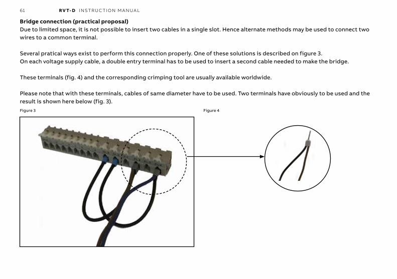
61 RV T- D I NS TR U C TI O N M A N UA L
Bridge connection (practical proposal)Due to limited space, it is not possible to insert two cables in a single slot. Hence alternate methods may be used to connect two wires to a common terminal.
Several pratical ways exist to perform this connection properly. One of these solutions is described on figure 3.On each voltage supply cable, a double entry terminal has to be used to insert a second cable needed to make the bridge.
These terminals (fig. 4) and the corresponding crimping tool are usually available worldwide.
Please note that with these terminals, cables of same diameter have to be used. Two terminals have obviously to be used and the result is shown here below (fig. 3).Figure 3 Figure 4

2GC
S21
00
14A
00
65
RE
V D
F 3
0.0
5.2
018
—We reserve the right to make technical changes or modify the contents of this document without prior notice. With re-gard to purchase orders, the agreed par-ticulars shall prevail. ABB does not accept any responsibility whatsoever for potential errors or possible lack of information in this document. We reserve all rights in this document and
in the subject matter and illustrations con-tained therein. Any reproduction, disclo-sure to third parties or utilization of its contents – in whole or in parts – is forbid-den without prior written consent of ABB.
© Copyright 2018 ABB. All rights reserved.Specifications subject to change without notice.
—s.a. ABB n.v.Power Quality ProductsAllée Centrale 10 Z.I. JumetB-6040 Charleroi (Jumet)BelgiumPhone: +32(0) 71 250 811Fax: +32(0) 71 344 007Email: [email protected]
new.abb.com/high-voltage/capacitors/lv


