• This manual provides important safety-related information. Thoroughly read and understand this manual before installing and using the product. • Keep this manual in a convenient location so that you can refer to it whenever necessary. • The contents of this manual are subject to change without notice. Uninterruptible Power Supply Instruction Manual BU300RW BU75RW/BU100RW/BU200RW/BU300RW
Transcript
• This manual provides important safety-related information. Thoroughly read and understand this manual before installing and using the product.
• Keep this manual in a convenient location so that you can refer to it whenever necessary.• The contents of this manual are subject to change without notice.
Uninterruptible Power Supply
Instruction Manual
BU300RW
BU75RW/BU100RW/BU200RW/BU300RW
i
IntroductionFeatures of this productThank you for purchasing Omron's Uninterruptible Power Supply (UPS).● The UPS protects computers and other devices from power failures, voltage variations, in-
stantaneous voltage drops, and surge voltage such as that caused by lightning (a phenom-enon in which extraordinary high voltage occurs instantaneously).
● Under normal conditions, commercial power is converted to direct current, and then it is converted back to a stable sine wave AC power before it is output.
When a commercial power failure is detected, the unit switches to battery supply to provide continuous sine wave output. This is especially suitable for use where power supply condi-tions are poor (for example, when there are large variations in voltage).
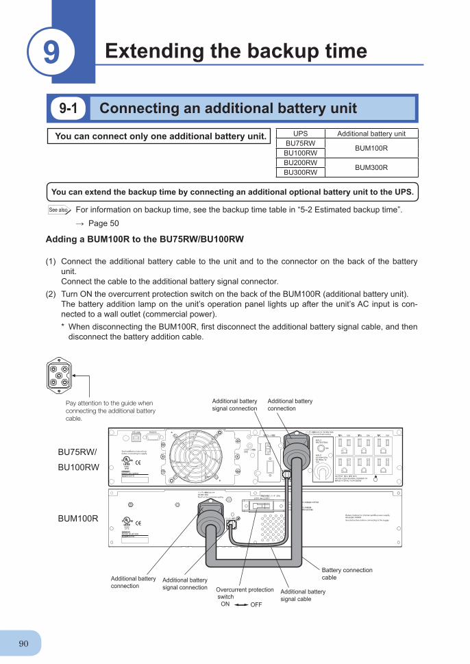
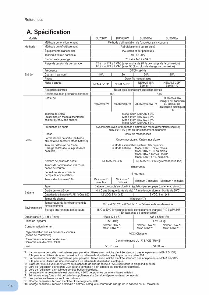
● Output capacity is 750VA/600W for the BU75RW, 1000VA/800W for the BU100RW, 2000VA/1600W for the BU200RW (when using 30A plug or power switchboard connection), and 3000VA/2400W for the BU300RW (when connected to power switchboard).
Notes on the use of the Backup Power Supply● This product is designed and manufactured for use with FA or OA equipment such as per-
sonal computers. Do not use it when very high reliability and safety are required as listed below.
• Medical equipment that may cause death directly• Applications that may cause injury (applications that directly affect the operation and con-
trol of planes, ships, railroads, elevators, and so on)• Applications that are always subjected to vibration such as cars and ships• Applications in which a failure of this product may cause signifi cant damage or effect to
the society and public (important computer systems, main communication equipment, public transportation systems, and so on)
• Equipment with the same level of importance● For equipment that greatly affects the safety of people and maintaining public functions,
special considerations related to operation, maintenance, and management must be taken such as duplicating the system and emergency power generation facilities.
● Observe the contents of this manual such as the use conditions and environments.● When you want to use this product for an important system that requires very high reliability,
contact the shop of purchase.● Do not modify/alter this product.
DisclaimersWe are not liable for any damage or secondary damage resulting from the use of our product, including malfunction and failure of equipment, connected devices, or software.
● Make sure to read the safety precautions before using the unit. ● In the event you transfer or sell this unit to a third party, please include all of the documenta-
tion that came with this unit. This is to ensure that the unit is used in line with the conditions described in the included documentation.
• This manual contains important safety-related information. Please read and understand the contents of the manual before beginning operation.
If you discover any omissions or errors in the manual, please contact the shop of pur-chase.
● Windows is the registered trademark of Microsoft Corporation in the United States and/or other countries.
● The names of other companies and products mentioned herein are the trademarks or regis-tered trademarks of their respective owners.
ii
IMPORTANT SAFETY INSTRUCTION1. SAVE THESE INSTRUCTIONS.
This manual contains important instructions for BU100RW/BU200RW/BU300RW that should be followed when using the UPS and batteries.
2. SYMBOL This symbol indicates earth ground.
This symbol indicates turning on UPS.
This symbol indicates turning off UPS.
3. INTERNAL BATTERYInternal battery voltage is 36V DC for BU100RW and 72V DC for BU200RW/BU300RW.
4. TEMPERATURE RATINGThe maximum ambient temperature of the UPS is 40°C.
5. ENVIRONMENTThe unit is intended for installation in a temperature controlled, indoor area free of conductive contaminants.
iii
INSTRUCTIONS DE SÉCURITÉ IMPORTANTES1. CONSERVER CES INSTRUCTIONS.
Ce manuel contient des instructions importantes pour BU100RW/BU200RW/BU300RW qui doivent être respectées lors de l’utilisation de l’onduleur et des batteries.
2. SYMBOLE Ce symbole indique la terre.
Ce symbole indique la mise sous tension de l’ASC.
Ce symbole indique la mise hors tension de l’ASC.
3. BATTERIE INTERNELa tension de la batterie interne est de 36V DC pour BU100RW et de 72V DC pour BU200RW/BU300RW.
4. TEMPÉRATURE NOMINALELa température ambiante maximale de l’ASC est de 40ºC.
5. ENVIRONNEMENTL’appareil est conçu pour une installation dans un espace intérieur à la température contrôlée et exempt de contaminants conducteurs.
iv
Procedure from installation to operation
Start
Installation/connection
Preparation for operation
Maintenance/ inspection
Yes
No
No
Yes Yes
No
Read “Safety precautions” Page vi
Remove the product from the package and check the contents
Page 1
Perform installation and connection Page 5
Check the operation and displays Page 29
Charge the battery Page 31
Measure the backup time Page 31
Read “Using the UPS monitoring software and contact signal” Page 68
1-1 Unpacking the product .......................................................................................................................... 11-2 Checking the contents ........................................................................................................................... 11-3 Name of each part ................................................................................................................................. 21-4 Explanation of symbols used on unit ..................................................................................................... 4
2. Installation and connection .............................................................................................................52-1 Precautions and notes on installation and connection ......................................................................................................... 52-2 Installation and connection .................................................................................................................. 132-3 Connecting the equipment .................................................................................................................. 212-4 Connecting the AC input...................................................................................................................... 242-5 Checking the operation ....................................................................................................................... 292-6 Charging the battery ............................................................................................................................ 312-7 Measuring the initial value of backup time .......................................................................................... 312-8 Recharging the battery ........................................................................................................................ 31
3. Operation ......................................................................................................................................32 3-1 Precautions and notes for operation ................................................................................................... 32
3-2 Start and stop procedures and basic operation ........................................................................................... 343-3 Interpreting beeps and displays ................................................................................................................... 37
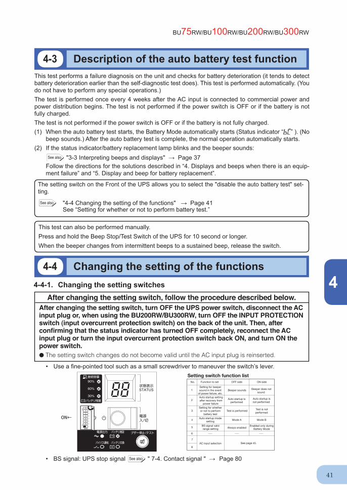
4. UPS functions ...............................................................................................................................40 4-1 Suspending a beep ............................................................................................................................. 40
4-2 Self-diagnosis test ............................................................................................................................... 404-3 Description of the auto battery test function ........................................................................................ 414-4 Changing the setting of the functions .................................................................................................. 41
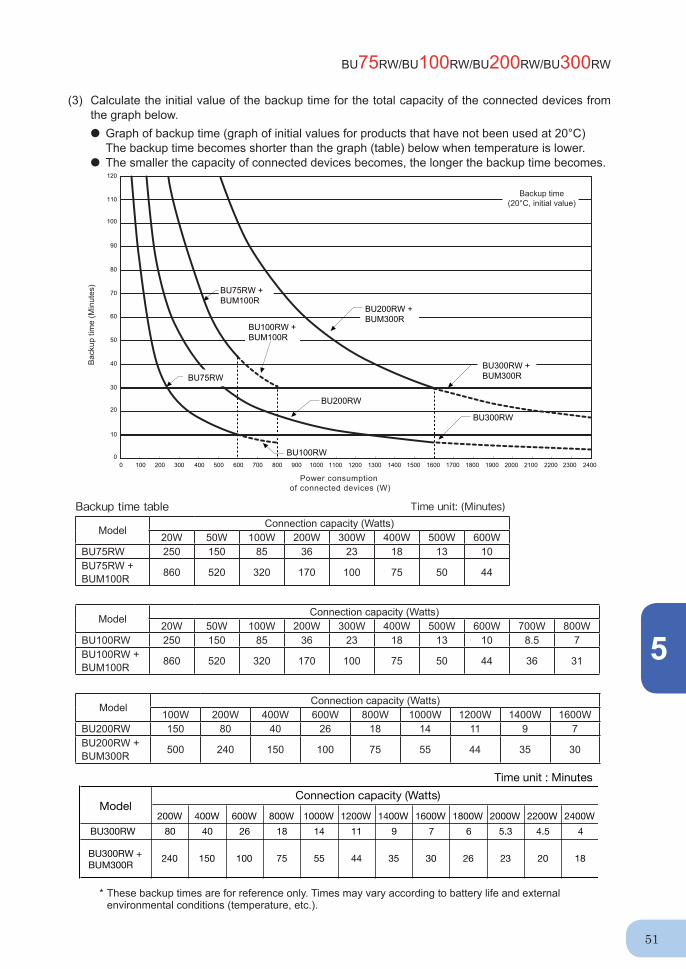
5. Measuring the backup time ..........................................................................................................505-1 How to measure backup time .............................................................................................................. 505-2 Estimated backup time ........................................................................................................................ 50
6. Maintenance and Inspection.........................................................................................................526-1 Checking the battery ........................................................................................................................... 536-2 Replacing the battery .......................................................................................................................... 546-3 Replacing the fan ................................................................................................................................ 646-4 Cleaning .............................................................................................................................................. 67
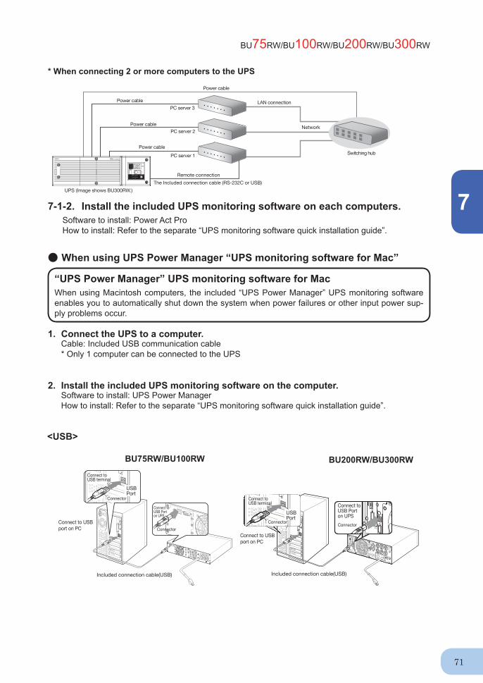
7. Using the UPS monitoring software and contact signal................................................................68 7-1 When using the included UPS monitoring software to perform auto shutdown .................................. 70
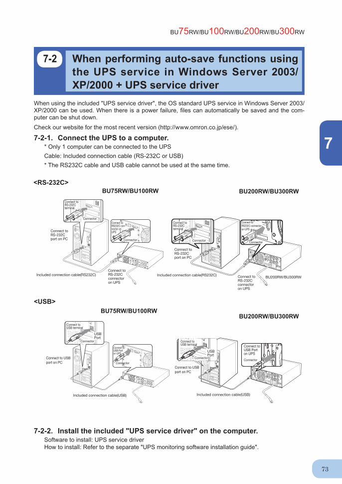
7-2 When performing auto-save functions using the UPS service in Windows Server 2003/XP/2000 + UPS service driver .............................................................................................................................. 737-3 When performing auto-save functions using the standard UPS service in Windows Server 2003/ XP/2000/NT ......................................................................................................................................... 747-4 Contact signal...................................................................................................................................... 80
8. Using an SNMP/Web card ............................................................................................................888-1 Adding an SNMP/Web card ................................................................................................................ 888-2 SNMP/Web card outline ...................................................................................................................... 89
9. Extending the backup time ...........................................................................................................909-1 Connecting an additional battery unit .................................................................................................. 90
A. Specifi cations ................................................................................................................................ 93 B. Dimensions .................................................................................................................................... 95 C. Circuit block diagram ..................................................................................................................... 97 D. Related products............................................................................................................................ 97
Safety precautions
vi
: Indicates prohibition. For example, indicates that disassembly is prohibited.
: Indicates obligation. For example, indicates that grounding is necessary.
Misuse may cause death or serious injury.Warning
Caution
Safety precautions
● The safety symbols and their meaning used in this manual are as follows:
* Property damage means damage to houses/household effects, livestock, and pets.
Note that events categorized as a caution required matter also may cause more serious results under certain conditions.
Do not use this unit when very high reliability and safety are required as listed below. This unit is designed and manufactured for use with FA or OA equipment such as personal computers. ● Medical equipment or system that may cause death directly.● Applications that directly affect the safety of people (For example, the operation and control of
cars and elevators).● Applications in which a failure of the unit may cause signifi cant damage to the society and public
(For example, essential computer systems and main communication equipment.)● Applications with the same level of importance.
Warning
Important information for safe operation is described.Be sure to read it before installation and start of use.
Misuse may cause injury or property damage.
Two or more people should work together to carry, unpack and install. ● Because the unit is heavy, you may injure yourself or drop the unit, or it may fall over.
Carry the unit considering its weight and balance, and place it on a stable and robust base.● Dropping or toppling the unit may cause injury.● The approximate weights of the units are 20kg (BU75RW/BU100RW) and 33kg (BU200RW/
BU300RW).● If you drop the unit, stop using it and have it inspected and repaired.
For repair, contact the shop of purchase.Keep plastic package bags out of reach of children.● Children may suffocate if they place their heads into plastic bags.Make sure to connect the unit’s AC input plug to a commercial power source with rated input voltage (100 VAC) and 50/60Hz frequency. ● Connecting to a commercial power source with a different rated input voltage or frequency may result in a fi re. ● The unit may fail.
Caution (for installation and connection)
BU75RW/BU100RW/BU200RWBU300RW
vii
When an abnormality (unusual sound or smell) occurs, turn OFF the unit’s power switch to stop the output, and stop the supply of commercial power. For the BU75RW/BU100RW, disconnect the AC input plug from the wall outlet. For the BU200RW/BU300RW, disconnect the AC input plug from the wall outlet (commercial power) or turn OFF the INPUT PROTECTION switch (input overcurrent protection switch) on the back of the unit. ● When performing maintenance on the connected devices, follow the above instructions to
ensure safety.Do not connect devices such as dryers, some solenoid valves, etc. , which have a half-wave rectifi er that allows only half-cycle AC power to fl ow through. ● Overcurrent may damage the UPS.Connect the unit to a wall outlet (commercial power) with the appropriate capacity (10A or greater for BU75RW, 12A or greater for BU100RW, 24A or greater for BU200RW, and 35A or greater for BU300RW). ● Otherwise, the power cord may be heated.● When equipment with the maximum output capacity is connected, a maximum current of 10A
(BU75RW), 12A (BU100RW), 24A (BU200RW) or 35A (BU300RW) fl ows. When using the 15A plug (NEMA 5-15P) that is connected to the BU200RW at shipment, the maximum capacity connectable to the output is approximately 1100VA/880W. ● When the power consumption exceeds this capacity, the input voltage becomes larger than 15A,
which may lead to overheating or fi re. . ● If the “overload” display appears, switch to a 20A or 30A plug or connect to a power switchboard
with a power capacity of 24A or more.
When using the 30A plug (NEMA L5-30P) that is connected to the BU300RW at shipment, the maximum capacity connectable to the output is approximately 2400VA/1920W. ● When the power consumption exceeds this capacity, the input voltage becomes larger than 30A,
which may lead to overheating or fi re. ● If “OVER LOAD” is displayed, connect to a power switchboard with a power capacity of 35A or
more.
When changing the input cable for the BU200RW and BU300RW, make sure to perform the connection as specifi ed. Make sure to properly match the AC input terminal with the appropriate wire color. Do not perform work on the AC input terminal while BU300RW is connected to a commercial power source.● Refer to “2-4 Connecting the AC input” on page 24. ● Failure to do so may result in electric shock or ground fault. Provide secure grounding.● After checking the plug shape of the wall outlet, directly connect the AC input plug of the unit to it. A
failure or leak that occurs when the unit is not properly grounded may result in electric shock. Do not disassemble, repair, or modify the unit.● Doing so may cause an electric shock or a fi re.Do not install the unit in other than specifi ed orientations.● Dropping or toppling the unit may cause injury.● If you install the unit in an orientation other than specifi ed, the unit cannot be protected from a
battery fl uid leakage.● Use the included vertical stand when positioning the unit vertically.
Caution (for installation and connection)
Safety precautions
viii
Do not use the unit where the maximum temperature exceeds 40°C.● The battery deteriorates rapidly.● Doing so may cause a failure or malfunction of the unit.Do not exceed the ranges specifi ed for environmental conditions during use/storage.Do not install or store the unit in the places listed below.● Do not store in places where the humidity is lower than 10% or higher than 90%.● Do not use the unit in places where the ambient temperature is lower than 0°C or higher than
40°C. ● Do not use in places where the humidity is lower than 25% or higher than 85%. ● Do not install/store the unit in closed places such as cabinets with no clearance, places where
there is fl ammable or corrosive gas, places with large amounts of dust, places exposed to direct sunlight, places exposed to shock or vibration, or outdoors.
● Installation or storing the unit in such a place may cause a fi re.
Do not connect equipment that exceeds the output capacity of the unit. You can use plug strip to connect additional devices, but do not connect devices that exceed the current capacity of the plug strip. ● The current protection of the unit may operate, which may stop the output.● The wiring of the plug strip heats up, which may cause a fi re.
Do not pinch or sharply bend the cable. Do not fold or knot the cable. ● Doing so may cause the cable to be damaged or heated, which may cause an electric shock or a fi re.● If the cable is damaged, stop using the unit and have the cable repaired. ● For repair, contact the shop of purchase.
All of the included accessories are designed to be used exclusively with the unit. Do not use the accessories with other devices.● Doing so may compromise the safety of devices. Do not block the air vents (front and rear).● Doing so will cause the internal temperature to rise, which may cause the unit to fail and the bat-
tery to deteriorate. ● Leave at least 5 cm of space between the vent and the wall.Do not connect a standalone transformer such as a voltage transformer or isolating transformer to the output side.● Overcurrent may damage the UPS or cause it to malfunction. ● There is no problem in connecting a transformer to the input side.Do not connect devices that cannot be used with commercial power supply.● When the unit’s power switch is turned ON and an error occurs with the connected device, by-
pass operation is performed and commercial power supply is supplied as is to the connected devices.
When installing the unit on a rack, place it on the lowest shelf. ● Injury may result if the unit falls.Make sure to use the mounting screws included with the brackets. ● Mounting screws other than those included may not be strong enough to support the unit, caus-
ing it to fall. ● If you attach the case using long screws other than those included with the product, you may
damage the internal parts of the unit.
Caution (for installation and connection)
BU75RW/BU100RW/BU200RWBU300RW
ix
Do not allow the unit to come in contact with water. If you drop the unit, stop using it. ● Doing so may cause an electric shock or a fi re.● If the unit becomes wet or is dropped, immediately stop using it, disconnect the AC input plug
from the wall outlet (commercial power) or, when using the BU200RW/BU300RW, turn OFF the INPUT PROTECTION switch (input overcurrent protection switch) on the back of the unit, and have it inspected and repaired.
● For repair, the shop of purchase.When the battery is dead, replace it immediately or stop using the unit.● Continuing the use of it may cause fi re or electric shock due to a fl uid leak.
Using a dry cloth, periodically wipe the dust from the AC input plug, input terminal block and power supply output receptacles. ● Accumulated dust may cause a fi re.Do not use the unit in a closed place and do not cover the unit. ● Doing so may cause abnormal heating or a fi re.If you notice an abnormal sound or smell, smoke, or leaking fluid, immediately turn OFF the unit’s power switch and stop the supply of commercial power. (For the BU75RW/BU100RW, disconnect the AC input plug from the wall outlet. For the BU200RW/BU300RW, disconnect the AC input plug from the wall outlet (commercial power) or turn OFF the INPUT PROTECTION switch (input overcurrent protection switch) on the back of the unit.) ● Using the unit under such conditions may cause a fi re.● If you notice such a condition, stop using the unit and contact the shop of purchase for inspection and
repairs.● Position the unit in such a way that you can immediately disconnect the AC input plug from
the wall outlet (commercial power) in the event a problem occurs, and if using the BU200RW/BU300RW, position it so that you can turn OFF the INPUT PROTECTION switch (input overcur-rent protection switch) on the back of the unit.
If fl uid leaks from the unit, do not touch the fl uid.● Doing so may cause blindness or burns.● If the fl uid contacts your eyes or skin, wash it out with lots of clean water and consult your doctor.Do not place objects heavier than 25kg on the unit, and do not drop heavy objects onto the unit. ● Doing so may cause distortion/damage to the case or a failure of the internal circuit, which may cause a fi re.BU300RW is equipped with a bypath circuit which is able to supply electric power to connected devices even when the inner control circuit is broken down by defects or malfunctions● Output is continuing even when all indicators of the front panel are off.● If you want to stop the output, either stop the source of commercial power, disconnect the AC
input plug from the wall outlet (commercial power) or, if using the BU200RW/BU300RW, turn OFF the input overcurrent protection switch (INPUT PROTECTION switch) on the back of the unit.
Ambient temperature Expected life20°C 4 to 5 years30°C 2 to 2.5 years
* The values in the table are the expected life under stan-dard use conditions and are not guaranteed.
Caution (for use)
Safety precautions
x
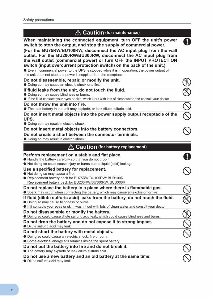
When maintaining the connected equipment, turn OFF the unit’s power switch to stop the output, and stop the supply of commercial power. (For the BU75RW/BU100RW, disconnect the AC input plug from the wall outlet. For the BU200RW/BU300RW, disconnect the AC input plug from the wall outlet (commercial power) or turn OFF the INPUT PROTECTION switch (input overcurrent protection switch) on the back of the unit.) ● Even if commercial power to the UPS is stopped while it is in operation, the power output of this unit does not stop and power is supplied from the receptacle. Do not disassemble, repair, or modify the unit.● Doing so may cause an electric shock or a fi re.If fl uid leaks from the unit, do not touch the fl uid.● Doing so may cause blindness or burns.● If the fl uid contacts your eyes or skin, wash it out with lots of clean water and consult your doctor.Do not throw the unit into fi re.● The lead battery in the unit may explode, or leak dilute sulfuric acid.Do not insert metal objects into the power supply output receptacle of the UPS.● Doing so may result in electric shock.Do not insert metal objects into the battery connectors.Do not create a short between the connector terminals. ● Doing so may result in electric shock.
Perform replacement on a stable and fl at place.● Handle the battery carefully so that you do not drop it.● Not doing so could cause injury or burns due to liquid (acid) leakage.Use a specifi ed battery for replacement.● Not doing so may cause a fi re.● Replacement battery pack for BU75RW/BU100RW: BUB100R
Replacement battery pack for BU200RW/BU300RW: BUB300R Do not replace the battery in a place where there is fl ammable gas.● Spark may occur when connecting the battery, which may cause an explosion or fi re.If fl uid (dilute sulfuric acid) leaks from the battery, do not touch the fl uid.● Doing so may cause blindness or burns.● If it contacts your eyes or skin, wash it out with lots of clean water and consult your doctor.Do not disassemble or modify the battery.● Doing so could cause dilute sulfuric acid leak, which could cause blindness and burns.Do not drop the battery and do not expose it to strong impact.● Dilute sulfuric acid may leak.Do not short the battery with metal objects.● Doing so could cause an electric shock, fi re or burn.● Some electrical energy still remains inside the spent battery.Do not put the battery into fi re and do not break it.● The battery may explode or leak dilute sulfuric acid.Do not use a new battery and an old battery at the same time.● Dilute sulfuric acid may leak.
Caution (for maintenance)
Caution (for battery replacement)
BU75RW/BU100RW/BU200RWBU300RW
xi
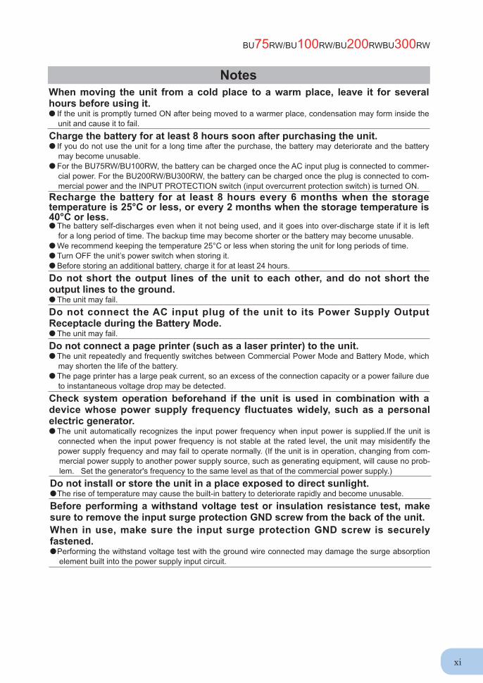
NotesWhen moving the unit from a cold place to a warm place, leave it for several hours before using it.● If the unit is promptly turned ON after being moved to a warmer place, condensation may form inside the
unit and cause it to fail. Charge the battery for at least 8 hours soon after purchasing the unit.● If you do not use the unit for a long time after the purchase, the battery may deteriorate and the battery
may become unusable.● For the BU75RW/BU100RW, the battery can be charged once the AC input plug is connected to commer-
cial power. For the BU200RW/BU300RW, the battery can be charged once the plug is connected to com-mercial power and the INPUT PROTECTION switch (input overcurrent protection switch) is turned ON.
Recharge the battery for at least 8 hours every 6 months when the storage temperature is 25°C or less, or every 2 months when the storage temperature is 40°C or less. ● The battery self-discharges even when it not being used, and it goes into over-discharge state if it is left
for a long period of time. The backup time may become shorter or the battery may become unusable. ● We recommend keeping the temperature 25°C or less when storing the unit for long periods of time. ● Turn OFF the unit’s power switch when storing it. ● Before storing an additional battery, charge it for at least 24 hours. Do not short the output lines of the unit to each other, and do not short the output lines to the ground. ● The unit may fail.Do not connect the AC input plug of the unit to its Power Supply Output Receptacle during the Battery Mode.● The unit may fail.Do not connect a page printer (such as a laser printer) to the unit.● The unit repeatedly and frequently switches between Commercial Power Mode and Battery Mode, which
may shorten the life of the battery.● The page printer has a large peak current, so an excess of the connection capacity or a power failure due
to instantaneous voltage drop may be detected.Check system operation beforehand if the unit is used in combination with a device whose power supply frequency fluctuates widely, such as a personal electric generator.● The unit automatically recognizes the input power frequency when input power is supplied.If the unit is
connected when the input power frequency is not stable at the rated level, the unit may misidentify the power supply frequency and may fail to operate normally. (If the unit is in operation, changing from com-mercial power supply to another power supply source, such as generating equipment, will cause no prob-lem. Set the generator's frequency to the same level as that of the commercial power supply.)
Do not install or store the unit in a place exposed to direct sunlight.● The rise of temperature may cause the built-in battery to deteriorate rapidly and become unusable.Before performing a withstand voltage test or insulation resistance test, make sure to remove the input surge protection GND screw from the back of the unit. When in use, make sure the input surge protection GND screw is securely fastened. ● Performing the withstand voltage test with the ground wire connected may damage the surge absorption
element built into the power supply input circuit.
Safety precautions
xii
ExplanationUsual operation ● You may either leave the power switch of the unit ON (operation status) or turn it OFF each time when
stopping the connected system. Choose whichever operation method is more convenient. We recommend turning OFF the power switch when you do not use connected devices for a long time.
● For the BU75RW/BU100RW, the battery can be charged once the AC input plug is connected to a com-mercial power source. For the BU200RW/BU300RW, the battery can be charged once the plug is con-nected and the INPUT PROTECTION switch (input overcurrent protection switch) is turned ON.
Quitting Battery Mode● If a power failure lasts for an extended period of time, the battery discharges and power output from the
unit stops. Shut down your computer after performing appropriate procedures (for example, saving data) while the unit is still supplying power.
Rebooting● If the battery discharges completely during a power failure, the output stops. After recovery from the
power failure, the unit automatically restarts and output begins. If you do not want to restart the connected devices, turn OFF the power switch of either the unit or the connected devices.
See also Setting switch 2 can be used to select whether or not auto restart is performed. See Page 42Scheduled operation using the UPS monitoring software ● When performing scheduled operation in which the UPS is stopped and a device such as a breaker is
used to stop the UPS at the same time that commercial power stops, specify a period of no more than 3 months for the start of the next operation.
If you specify a period longer than 3 months, the internal timer is reset and the scheduled operation does not start. Note that this period reduces to approximately half when the battery is dead. If a period of 3 months is exceeded, you start operation by supplying commercial power and pressing the start switch. However, if the battery is dead, you may not be able to start operation.
In this case, replace the battery according to the instructions in “6-2 Replacing the battery” on page 54.
Pb
NotesBefore stopping the commercial power to the unit, turn OFF the power switch of the unit.● The unit enters Battery Mode when commercial power is stopped. If you frequently use the unit in Battery
Mode, the battery life may be signifi cantly shortened. If this unit is used with an inductive device such as a coil or motor, check the operation beforehand.● With some types of devices, the effect of inrush current may cause this unit to stop operating properly.In the event you transfer or sell this unit to a third party, please include all of the documentation that came with the unit. This is to ensure that the unit is used in line with the conditions described in the included documentation. ● This manual contains important safety-related information. Please read and understand the contents of
the manual before beginning operation.
This unit uses lead acid batteries, ● Which are a valuable recyclable resource. Please recycle.
Take measures for handling unforeseen accidents, such as data backup and system redundancy. ● The output may stop when there is a circuit failure in the UPS.
BU75RW/BU100RW/BU200RWBU300RW
xiii
: Indique une interdiction. Par exemple, indique que le démontage est interdit.
: Indique une obligation. Par exemple, indique que la mise à la terre est nécessaire.
Une mauvaise utilisation peut entraîner la mort ou des blessures graves.Avertissement
Attention
● Les symboles de sécurité et leur signifi cation utilisés dans ce manuel sont les suivants :
* Les dommages matériels signifi ent les dommages aux habitations / effets mobiliers, bétail et animaux domestiques.
Noter que les événements classés comme mise en garde réglementaire peuvent également avoir des conséquences plus graves dans certaines conditions.
Ne pas utiliser cet appareil si une très haute fi abilité ou sécurité est nécessaire comme dans les cas indiqués ci-dessous. Cet appareil a été conçu et fabriqué pour être utilisé avec des équipements d'automation informatique ou industrielle comme des ordinateurs personnels. ● Équipement ou système médical pouvant directement entraîner la mort.● Applications qui affectent directement la sécurité des personnes (Par exemple, le fonctionnement
et le contrôle des voitures et des ascenseurs).● Applications pour lesquelles une défaillance de l’appareil peut causer des dommages importants
sur la société et le public (Par exemple, les systèmes informatiques essentiels et le matériel de communication principal.)
● Applications d’un niveau d’importance similaire.
Avertissement
Une mauvaise utilisation peut entraîner des blessures ou des dommages matériels.
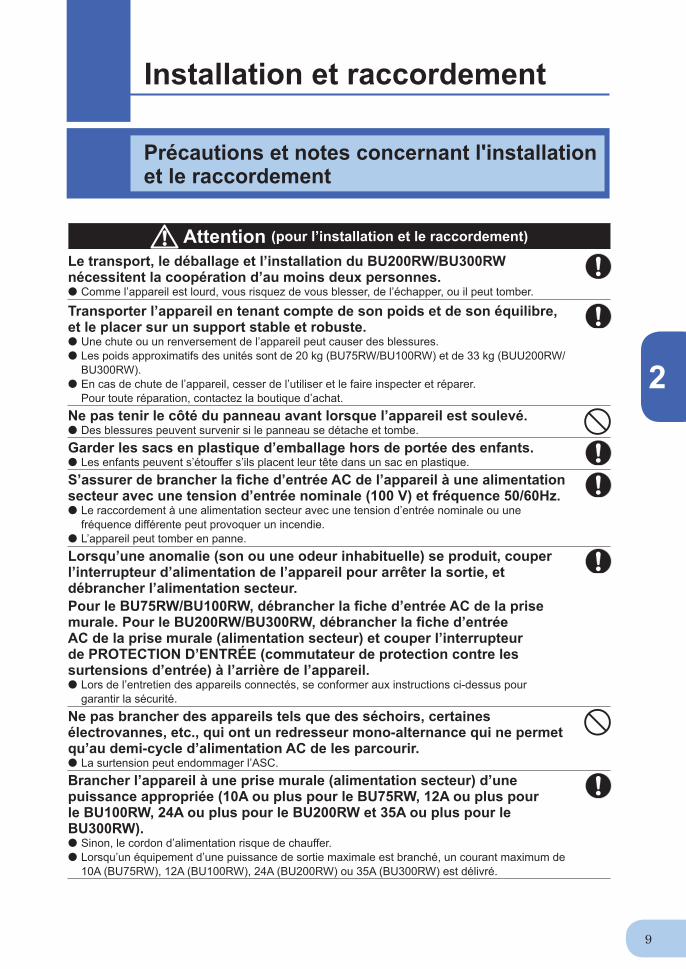
Le transport, le déballage et l'installation nécessitent la coopération d'au moins deux personnes. ● Comme l’appareil est lourd, vous risquez de vous blesser, de l’échapper, ou il peut tomber.
Transporter l’appareil en tenant compte de son poids et de son équilibre, et le placer sur un support stable et robuste.● Une chute ou un renversement de l’appareil peut causer des blessures.● Les poids approximatifs des unités sont de 20 kg (BU75RW/BU100RW) et de 33 kg (BU200RW/
BU300RW).● En cas de chute de l’appareil, cesser de l’utiliser et le faire inspecter et réparer.
Pour toute réparation, contactez la boutique d’achat.Garder les sacs en plastique d’emballage hors de portée des enfants.● Les enfants peuvent s’étouffer s’ils placent leur tête dans un sac en plastique.S’assurer de brancher la fi che d’entrée AC de l’appareil à une alimentation secteur source avec une tension d’entrée nominale (100 VAC) et une fréquence de 50/60Hz. ● Le raccordement à une alimentation secteur avec une tension d’entrée nominale ou une fréquence différente peut provoquer un incendie. ● L’appareil peut tomber en panne.
Attention (pour l’installation et le raccordement)
Consignes de sécuritéDes informations importantes pour un fonctionnement en toute sécurité sont données.À lire impérativement avant de commencer l’installation et l’utilisation.
Safety precautions
xiv
Lorsqu’une anomalie (son ou une odeur inhabituelle) se produit, couper l’interrupteur d’alimentation de l’appareil pour arrêter la sortie, et débrancher l’alimentation secteur. Pour le BU75RW/BU100RW, débrancher la fi che d’entrée AC de la prise murale. Pour le BU200RW/BU300RW, débrancher la fi che d’entrée AC de la prise m urale (alimentation secteur) ou couper l’interrupteur de PROTECTION D’ENTRÉE (commutateur de protection contre les surtensions d’entrée) à l’arrière de l’appareil.● Lors de l’entretien des appareils connectés, se conformer aux instructions ci-dessus pour
garantir la sécurité.Ne pas brancher des appareils tels que des séchoirs, certaines électrovannes, etc., qui ont un redresseur mono-alternance qui ne permet qu’au demi-cycle d’alimentation AC de les parcourir.● La surtension peut endommager l’ASC.Brancher l’appareil à une prise murale (alimentation secteur) d’une puissance appropriée (10A ou plus pour le BU75RW, 12A ou plus pour le BU100RW, 24A ou plus pour le BU200RW et 35A ou plus pour le BU300RW).● Sinon, le cordon d’alimentation risque de chauffer.● Lorsqu’un équipement d’une puissance de sortie maximale est branché, un courant maximum de
10A (BU75RW), 12A (BU100RW), 24A (BU200RW) ou 35A (BU300RW) est délivré.Lors de l’utilisation de la prise 15A (NEMA 5-15P) qui est connectée au BU200RW lors de l’expédition, la puissance maximale branchable en sortie est d’environ 1100VA/880W.● Lorsque la consommation électrique dépasse cette puissance, la tension d’entrée atteint alors
plus de 15A, ce qui peut provoquer une surchauffe ou un incendie.● Si l’affi chage “overload” (surcharge) apparaît, commuter sur une prise 20A ou 30A ou se connecter
à un tableau de distribution électrique d’une puissance de 24A ou plus.Lors de l’utilisation de la prise 30A (NEMA L5-30P) qui est connectée au BU300RW lors de l’expédition, la capacité maximale branchable en sortie est d’environ 2400VA/1920W.● Lorsque la consommation électrique dépasse cette puissance, la tension d’entrée atteint alors
plus de 30A, ce qui peut provoquer une surchauffe ou un incendie.● Si “OVER LOAD” (SURCHARGE) s’affi che, se connecter à un tableau de distribution électrique
d’une puissance de 35A ou plus.Lors du changement du câble d’entrée pour le BU200RW et le BU300RW, s’assurer d’effectuer le raccordement comme spécifi é. S’assurer de bien faire correspondre la borne d’entrée AC avec la couleur de fi l appropriée.Ne pas effectuer de travaux sur la borne d’entrée AC alors que le BU300RW est relié à une alimentation secteur.● Consulter “2-4 Connexion de l’entrée AC” à la page 24.● Ne pas le faire peut entraîner un choc électrique ou une faute à la terre.Assurer une mise à la terre correcte.● Après vérifi cation de la forme de la prise murale, y brancher directement la fi che d'entrée AC de
l'appareil. Une panne ou une fuite se produisant lorsque l'appareil n'est pas correctement relié à la terre peut provoquer un choc électrique.
Ne pas démonter, réparer ou modifi er l'appareil.● Cela peut provoquer un choc électrique ou un incendie.
Attention (pour l’installation et le raccordement)
BU75RW/BU100RW/BU200RWBU300RW
xv
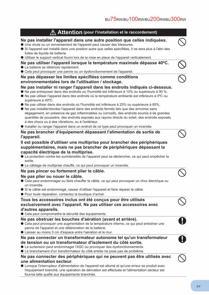
Ne pas installer l'appareil dans une autre position que celles indiquées.● Une chute ou un renversement de l'appareil peut causer des blessures.● Si l'appareil est installé dans une position autre que celles spécifi ées, il ne sera plus à l'abri des
fuites de liquide de batterie.● Utiliser le support vertical fourni lors de la mise en place de l'appareil verticalement.Ne pas utiliser l'appareil lorsque la température maximale dépasse 40ºC.● La batterie se détériore rapidement.● Cela peut provoquer une panne ou un dysfonctionnement de l'appareil.Ne pas dépasser les limites spécifi ées comme conditions environnementales lors de l'utilisation / stockage.Ne pas installer ni ranger l'appareil dans les endroits indiqués ci-dessous.● Ne pas entreposer dans des endroits où l'humidité est inférieure à 10% ou supérieure à 90 %.● Ne pas utiliser l'appareil dans des endroits où la température ambiante est inférieure à 0ºC ou
supérieure à 40ºC.● Ne pas utiliser dans des endroits où l'humidité est inférieure à 25% ou supérieure à 85%.● Ne pas installer/stocker l'appareil dans des endroits fermés tels que des armoires sans
dégagement, en présence de gaz infl ammables ou corrosifs, des endroits soumis à de grandes quantités de poussière, des endroits exposés aux rayons directs du soleil, des endroits exposés à des chocs ou à des vibrations, ou à l'extérieur.
● Installer ou ranger l'appareil dans un endroit de ce type peut provoquer un incendie.
Ne pas brancher d'équipement dépassant l'alimentation de sortie de l'appareil.Il est possible d'utiliser une multiprise pour brancher des périphériques supplémentaires, mais ne pas brancher de périphériques dépassant la capacité électrique de la multiprise.● La protection contre les surintensités de l'appareil peut se déclencher, ce qui peut empêcher la
sortie.● Le câblage de multiprise chauffe, ce qui peut provoquer un incendie.
Ne pas pincer ou fortement plier le câble.Ne pas plier ou nouer le câble.● Cela peut endommager ou faire chauffer le câble, ce qui peut provoquer un choc électrique ou
un incendie.● Si le câble est endommagé, cesser d'utiliser l'appareil et faire réparer le câble.● Pour toute réparation, contactez la boutique d’achat.
Tous les accessoires inclus ont été conçus pour être utilisés exclusivement avec l'appareil. Ne pas utiliser ces accessoires avec d'autres appareils.● Cela peut compromettre la sécurité des équipements.Ne pas obstruer les bouches d'aération (avant et arrière).● Cela peut provoquer une augmentation de la température interne, ce qui peut entraîner une
panne de l'appareil et une détérioration de la batterie.● Laisser au moins 5 cm d'espace entre l'aération et le mur.Ne pas connecter un transformateur autonome tel qu'un transformateur de tension ou un transformateur d'isolement du côté sortie.● La surtension peut endommager l'ASC ou provoquer des dysfonctionnements.● Le branchement d'un transformateur du côté entrée ne pose pas de problème.Ne pas connecter des périphériques qui ne peuvent pas être utilisés avec une alimentation secteur.● Lorsque l'interrupteur d'alimentation de l'appareil est allumé et qu'une erreur se produit avec
l'équipement branché, une opération de dérivation est effectuée et l'alimentation secteur est fournie telle quelle aux équipements branchés.
Attention (pour l'installation et le raccordement)
Safety precautions
xvi
Ne pas laisser l'appareil entrer en contact avec de l'eau.Si l'appareil tombe, cesser de l'utiliser.● Cela peut provoquer un choc électrique ou un incendie.● Si l'appareil est mouillé ou tombe, cesser immédiatement de l'utiliser, retirer la fi che d'entrée AC
de la prise murale (alimentation secteur) ou, en cas d'utilisation du BU200RW/BU300RW, couper l'interrupteur de PROTECTION D'ENTRÉE (commutateur de protection contre les surtensions d'entrée) à l'arrière de l'appareil et le faire inspecter et réparer.
● Pour les réparations, contactez la boutique d’achat.Lorsque la batterie est morte, la remplacer immédiatement ou cesser d'utiliser l'appareil.● Continuer l'utilisation pourrait causer un incendie ou une décharge électrique suite à une fuite de
liquide.
Température ambiante Durée de vie prévue
20°C 4 à 5 ans30°C 2 à 2,5 ans
* Les valeurs du tableau sont la durée de vie prévue dans les conditions normales d'utilisation mais ne sont pas garanties.
Essuyer régulièrement la poussière de la fi che d'entrée AC, du bornier d'entrée et des prises de sortie d'alimentation avec un chiffon sec.● Une accumulation de poussière peut provoquer un incendie.Ne pas utiliser l'appareil dans un endroit fermé et ne pas le couvrir.● Cela peut provoquer un échauffement anormal ou un incendie.En présence d'un son ou odeur anormale, de fumée ou de fuite de liquide, couper immédiatement l'interrupteur d'alimentation et débrancher l'alimentation secteur.Pour le BU75RW/BU100RW, débrancher la fi che d'entrée AC de la prise murale. Pour le BU200RW/BU300RW, débrancher la fi che d'entrée AC de la prise murale (alimentation secteur) et couper l'interrupteur de PROTECTION D'ENTRÉE (commutateur de protection contre les surtensions d'entrée) à l'arrière de l'appareil.● L'utilisation de l'appareil dans ces conditions peut provoquer un incendie.● En cas de constatation d'un tel état, cesser d'utiliser l'appareil et contactez la boutique d’achat
pour inspection et réparation.● Placer l'appareil de manière à pouvoir immédiatement débrancher la fi che d'entrée AC de la
prise murale (alimentation secteur) dans le cas où un problème survient, et si vous utilisez le BU200RW / BU300RW, le placer de manière à pouvoir couper l'interrupteur de PROTECTION D'ENTRÉE (commutateur de protection contre les surtensions d'entrée) à l'arrière de l'appareil
Si des fuites de liquide depuis l'appareil se produisent, ne pas toucher ce liquide.● Cela peut provoquer la cécité ou des brûlures.● Si le liquide entre en contact avec les yeux ou la peau, rincer abondamment à l'eau claire avant
de consulter un médecin.
Lors de l'installation de l'appareil sur un rack, le placer sur l'étagère la plus basse.● Des blessures peuvent survenir si l'appareil tombe.Toujours utiliser les vis de montage fournies avec les supports.● Des vis de fi xation autres que celles fournies peuvent ne pas être assez résistantes pour
supporter l'appareil et entraîner sa chute.● Si le boîtier est fi xé à l'aide de longues vis autres que celles fournies avec le produit, les
composants internes de l'appareil risquent d'être endommagés.
Attention (pour l'installation et le raccordement)
Attention (pour l'utilisation)
BU75RW/BU100RW/BU200RWBU300RW
xvii
Ne pas placer d'objet de plus de 25 kg sur l'appareil, et ne pas laisser tomber des objets lourds sur l'appareil.● Cela peut provoquer une altération/dommages du boîtier ou une panne du circuit interne, ce qui
peut provoquer un incendie.Le BU300RW est équipé d'un circuit de dérivation qui peut fournir une alimentation électrique à des dispositifs raccordés, même lorsque le circuit de commande interne est coupé par des défaillances ou des dysfonctionnements.● La sortie se poursuit même lorsque tous les indicateurs du panneau avant sont éteints.● Si vous voulez arrêter la sortie, arrêtez l'alimentation secteur et débranchez la fi che d'entrée
d'alimentation de la prise murale (alimentation secteur) ou, si vous utilisez le BU200RW/BU300RW, coupez le commutateur de protection contre les surtensions d'entrée (interrupteur de PROTECTION D'ENTRÉE) à l'arrière de l'appareil.
Lors de l'entretien de l'équipement connecté, couper l'interrupteur d'alimentation de l'appareil pour arrêter la sortie, et débrancher l'alimentation secteur.Pour le BU75RW/BU100RW, débrancher la fi che d'entrée AC de la prise murale. Pour le BU200RW/BU300RW, débrancher la fi che d'entrée AC de la prise murale (alimentation secteur) et couper l'interrupteur de PROTECTION D'ENTRÉE (commutateur de protection contre les surtensions d'entrée) à l'arrière de l'appareil.● Même si l'alimentation secteur est arrêtée alors que l'ASC est en marche, l'alimentation de sortie
de l'appareil ne s'arrête pas et est fournie par la prise.Ne pas démonter, réparer ou modifi er l'appareil.● Cela peut provoquer un choc électrique ou un incendie.Si des fuites de liquide depuis l'appareil se produisent, ne pas toucher ce liquide.● Cela peut provoquer la cécité ou des brûlures.● Si le liquide entre en contact avec les yeux ou la peau, rincer abondamment à l'eau claire avant
de consulter un médecin.Ne pas jeter l'appareil au feu.● La batterie au plomb dans l'appareil peut exploser ou laisser fuir de l'acide sulfurique dilué.Ne pas insérer d'objets métalliques dans la prise de sortie de l'alimentation électrique de l'ASC.● Cela peut provoquer un choc électrique.Ne pas insérer d'objets métalliques dans les connecteurs de la batterie.Ne pas créer de court-circuit entre les bornes du connecteur. ● Cela peut provoquer un choc électrique.
Attention (pour l'utilisation)
Attention (pour le remplacement de la batterie)
Effectuer le remplacement à un endroit stable et plat.● Manipuler soigneusement la batterie afi n de ne pas la laisser tomber.● Ne pas le faire peut entraîner des blessures ou des brûlures dues au liquide (acide) de fuite.Utiliser une batterie spécifi ée pour le remplacement.● Ne pas le faire peut provoquer un incendie.● Batterie de rechange pour BU75RW/BU100RW : BUB100R
Batterie de rechange pour le BU200RW/BU300RW : BUB300RNe pas changer la batterie en présence de gaz infl ammable.● Une étincelle peut se produire lors de la connexion de la batterie, ce qui peut provoquer une
explosion ou un incendie.
Safety precautions
xviii
Attention (pour le remplacement de la batterie)
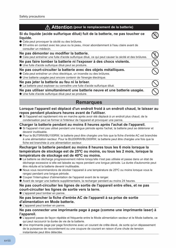
Si du liquide (acide sulfurique dilué) fuit de la batterie, ne pas toucher ce liquide.● Cela peut provoquer la cécité ou des brûlures.● S'il entre en contact avec les yeux ou la peau, rincer abondamment à l'eau claire avant de
consulter un médecin.Ne pas démonter ou modifi er la batterie.● Cela peut entraîner une fuite d'acide sulfurique dilué, ce qui peut causer la cécité et des brûlures.Ne pas faire tomber la batterie ni l'exposer à des chocs violents.● Une fuite d'acide sulfurique dilué peut se produire.Ne pas court-circuiter la batterie avec des objets métalliques.● Cela peut entraîner un choc électrique, un incendie ou des brûlures.● Une batterie usagée peut encore contenir de l'énergie électrique.Ne pas jeter la batterie au feu ni la briser.● La batterie peut exploser ou connaître une fuite d'acide sulfurique dilué.Ne pas utiliser simultanément une batterie neuve et une batterie usagée.● Une fuite d'acide sulfurique dilué peut se produire.
RemarquesLorsque l'appareil est déplacé d'un endroit froid à un endroit chaud, le laisser au repos pendant plusieurs heures avant de l'utiliser.● Si l'appareil est rapidement mis en marche après avoir été déplacé à un endroit plus chaud, de la
condensation peut se former à l'intérieur de l'appareil et provoquer une panne.Charger la batterie pendant au moins 8 heures après l'achat de l'appareil.● Si l'appareil n'est pas utilisé pendant une longue période après l'achat, la batterie peut se détériorer et
devenir inutilisable.● Pour le BU75RW/BU100RW, la batterie peut être chargée une fois que la fi che d'entrée AC est branchée
à une alimentation secteur. Pour le BU200RW/BU300RW, la batterie peut être chargée une fois que la fi che est branchée à une alimentation secteur.
Recharger la batterie pendant au moins 8 heures tous les 6 mois lorsque la température de stockage est de 25ºC ou moins, ou tous les 2 mois, lorsque la température de stockage est de 40ºC ou moins.● La batterie se décharge progressivement même lorsqu'elle n'est pas utilisée et passe dans un état de
décharge excessive si elle est laissée au repos pendant une longue période. La durée d'autonomie peut être réduite et la batterie devenir inutilisable.
● Nous vous recommandons de stocker l'appareil à une température de 25ºC ou moins lorsque vous le rangez pendant une longue période.
● Couper l'interrupteur d'alimentation de l'appareil avant de le ranger.● Avant de ranger une batterie supplémentaire, la recharger pendant au moins 24 heures.Ne pas court-circuiter les lignes de sortie de l'appareil entre elles, et ne pas court-circuiter les lignes de sortie vers la terre.● L'appareil peut tomber en panne.Ne pas brancher la fi che d'entrée AC de l'appareil à sa prise de sortie d'alimentation en Mode batterie.● L'appareil peut tomber en panne.Ne pas connecter une imprimante page à page (comme une imprimante laser) à l'appareil.● L'appareil passe de façon répétée et fréquente entre le Mode alimentation secteur et le Mode batterie, ce
qui peut raccourcir la durée de vie de la batterie.● Une imprimante page par page fonctionne avec un courant de crête élevé, de sorte qu'un dépassement
de la puissance de raccordement ou une coupure de courant en raison d'une chute de tension instantanée peut être détectée.
BU75RW/BU100RW/BU200RWBU300RW
xix
RemarquesVérifi er le fonctionnement du système préalablement si l'appareil est utilisé en combinaison avec un équipement dont la fréquence d'alimentation électrique varie de façon importante, comme un générateur électrique individuel.● L'appareil reconnaît automatiquement la fréquence de l'alimentation d'entrée lorsque l'alimentation
d'entrée est fournie. Si l'appareil est branché lorsque la fréquence de l'alimentation d'entrée n'est pas stable au niveau nominal, l'appareil risque de mal identifi er la fréquence d'alimentation et de ne pas fonctionner. (Si l'appareil est en marche, le passage de l'alimentation secteur à une autre source d'alimentation, tel un générateur, ne pose pas de problème. Régler la fréquence du générateur au même niveau que celle de l'alimentation secteur.)
Ne pas installer ni ranger l'appareil dans un endroit exposé à la lumière directe du soleil.● L'augmentation de la température peut provoquer une détérioration accélérée de la batterie intégrée et la
rendre inutilisable.Avant d'effectuer un test de rigidité diélectrique ou un test de résistance d'isolation, s'assurer de bien retirer la vis GND de protection contre les surtensions d'entrée à l'arrière de l'appareil.Lors de l'utilisation, s'assurer que la vis GND de protection contre les surtensions d'entrée est bien serrée.● Effectuer un essai de rigidité diélectrique avec le fi l de mise à la terre relié risque d'endommager l'élément
d'absorption de surtension intégré dans le circuit d'entrée de l'alimentation.Avant d'arrêter l'alimentation secteur de l'appareil, éteindre l'interrupteur d'alimentation de l'appareil.● L'appareil passe en Mode batterie lorsque l'alimentation secteur est arrêtée. Si l'appareil est fréquemment
utilisé en Mode batterie, l'autonomie de la batterie peut se voir considérablement réduite.Si cet appareil est utilisé avec un dispositif inductif comme une bobine ou un moteur, vérifi er préalablement le fonctionnement.● Avec certains types d'équipements, l'effet du courant d'appel peut interrompre le fonctionnement normal
de l'appareil.Dans le cas de la cession ou de la vente de cet appareil à un tiers, veuillez inclure toute la documentation fournie avec l'appareil. Il s'agit de veiller à ce que l'appareil soit utilisé conformément aux conditions décrites dans la documentation fournie.● Ce manuel contient des informations importantes relatives à la sécurité. Veuillez bien lire et comprendre
le contenu du manuel avant de commencer à utiliser le produit.
Cet appareil utilise des batteries● au plomb qui sont de précieuses ressources recyclables. Veuillez les recycler.
Prendre les mesures nécessaires pour répondre aux accidents imprévisibles, telles que les sauvegardes de données et la redondance du système.● La sortie peut s'arrêter lors d'une panne de circuit dans l'ASC.
Pb
1
1
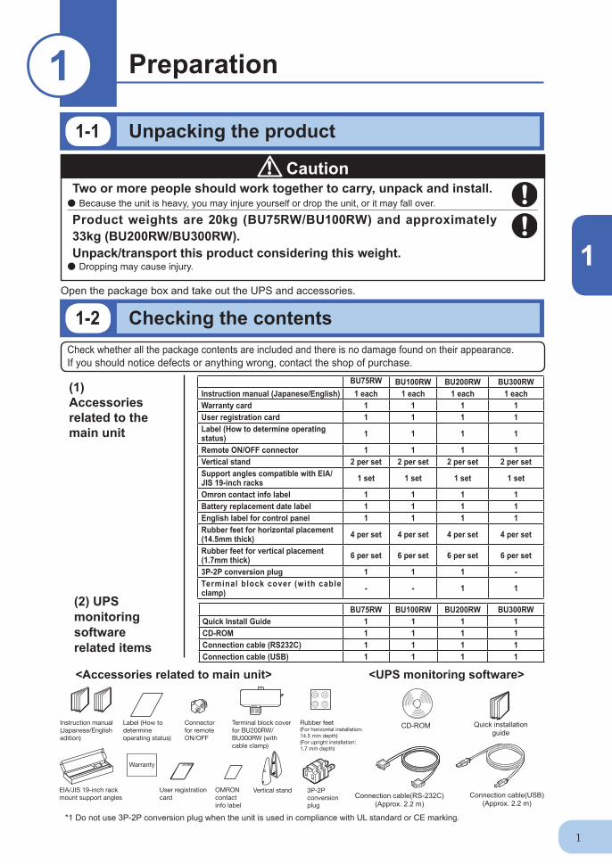
Open the package box and take out the UPS and accessories.
Two or more people should work together to carry, unpack and install. ● Because the unit is heavy, you may injure yourself or drop the unit, or it may fall over.
Product weights are 20kg (BU75RW/BU100RW) and approximately 33kg (BU200RW/BU300RW).Unpack/transport this product considering this weight.● Dropping may cause injury.
Caution
Instruction manual(Japanese/Englishedition)
Label (How todetermineoperating status)
User registrationcard
Connectorfor remote ON/OFF
Terminal block cover for BU200RW/BU300RW (with cable clamp)
Warranty
OMRON contactinfo label
Rubber feet(For horizontal installation: 14.5 mm depth)(For upright installation: 1.7 mm depth)
EIA/JIS 19-inch rackmount support angles
Vertical stand 3P-2P conversion plug
CD-ROM
Connection cable(USB) (Approx. 2.2 m)
<Accessories related to main unit> <UPS monitoring software>
Connection cable(RS-232C) (Approx. 2.2 m)
1-1 Unpacking the product
Preparation11
1-2 Checking the contentsCheck whether all the package contents are included and there is no damage found on their appearance.If you should notice defects or anything wrong, contact the shop of purchase.
(1) Accessories related to the main unit
(2) UPS monitoring software related items
Quick installation guide
BU75RW BU100RW BU200RW BU300RWInstruction manual (Japanese/English) 1 each 1 each 1 each 1 eachWarranty card 1 1 1 1User registration card 1 1 1 1Label (How to determine operating status) 1 1 1 1
Remote ON/OFF connector 1 1 1 1Vertical stand 2 per set 2 per set 2 per set 2 per setSupport angles compatible with EIA/JIS 19-inch racks 1 set 1 set 1 set 1 set
Omron contact info label 1 1 1 1Battery replacement date label 1 1 1 1English label for control panel 1 1 1 1Rubber feet for horizontal placement (14.5mm thick) 4 per set 4 per set 4 per set 4 per set
Rubber feet for vertical placement (1.7mm thick) 6 per set 6 per set 6 per set 6 per set
This section describes the name of each part of the UPS.For information on the function of each part, refer to "2. Installation and connection" on page 5 and "3. Operation" on page 32 that provides the details.
Front view
< Enlarged view of the display panel >
A. Status indicator digital display B. Power switch C. Beep stop/test switchD. Battery addition lampE. Battery replacement lampF. Bypass operation lamp (The input power supply is output as is.)G. Power supply output lampH. Setting switch cover/Setting switchesI. Connection capacity/battery level meter
ON
DIP
1
2
56
78
3
4
AI
B
C
H
E DG F
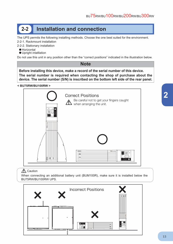
<BU75RW/BU100RW>
<Control display panel><Air vent>
1-3 Name of each part
<Front cooling fan (intake) >
<Control display panel>
<BU200RW/300RW> (Image shows BU300RW)
<Air vent>
BU75RW/BU100RW/BU200RW/BU300RW
1
3
Rear view
C HD F
E
BA G I J K L
N
M
OQRS P
A. Contact signal card B. Remote ON/OFF connectorC. Contact signal connectorD. USB connectorE. RS-232C connectorF. Rear cooling fan (exhaust) G. Input surge protection GND H. Additional battery signal connectorI. Additional battery connectorJ. Power supply output receptacle AK. Power supply output receptacle B
L. Power supply output receptacle CM. Grounding terminalN. AC input overcurrent protection switch 45AO. Terminal CoverP. AC input cableQ. Power supply output receptacle C overcurrent breaker (20A) R. Power supply output receptacle B overcurrent breaker (20A) S. Power supply output receptacle A overcurrent breaker (20A)
<BU200RW/BU300RW>
<BU75RW/BU100RW>
C D E F H
MNO
I JGBA K L
A. USB connectorB. RS-232C connector C. Cooling fanD. Input surge protection GNDE. Contact signal cardF. Remote ON/OFF connector G. Contact signal connectorH. Additional battery connector
I. AC input overcurrent protection switch INPUT PROTECTION 15AJ. Power supply output receptacle AK. Power supply output receptacle BL. Power supply output receptacle CM. Grounding terminal N. AC input cableO. Additional battery signal connector
1.Preparation
4
1-4 Explanation of symbols used on unit
Symbol Description
Start the UPS.
Stop the UPS.
Suspend a beep.
UPS output power enabled, supplied by operating on line mode, battery mode.
Bypass output “ON”.
Additional battery unit connected to the UPS.
Batteries at end of useful life, necessary to replace the batteries.
Two or more people should work together to carry, unpack and install the BU200RW/BU300RW. ● Because the unit is heavy, you may injure yourself or drop the unit, or it may fall over.
Carry the unit considering its weight and balance, and place it on a stable and robust base.● Dropping or toppling the unit may cause injury.● The approximate weights of the units are 20kg (BU75RW/BU100RW) and 33kg (BUU200RW/
BU300RW). ● If you drop the unit, stop using it and have it inspected and repaired.
For repair, contact the shop of purchase.Do not hold the side of the front panel when lifting.● Injury may result if the panel comes off and falls.Keep plastic package bags out of reach of children.● Children may suffocate if they place their heads into plastic bags.Make sure to connect the unit’s AC input plug to a commercial power source with rated input voltage (100 VAC) and 50/60Hz frequency. ● Connecting to a commercial power source with a different rated input voltage or frequency may result in a fi re. ● The unit may fail.When an abnormality (unusual sound or smell) occurs, turn OFF the unit’s power switch to stop the output, and stop the supply of commercial power. For the BU75RW/BU100RW, disconnect the AC input plug from the wall outlet. For the BU200RW/BU300RW, disconnect the AC input plug from the wall outlet (commercial power) or turn OFF the INPUT PROTECTION switch (input overcurrent protection switch) on the back of the unit.● When performing maintenance on the connected devices, follow the above instructions to ensure
safety.Do not connect devices such as dryers, some solenoid valves, etc. , which have a half-wave rectifi er that allows only half-cycle AC power to fl ow through. ● Overcurrent may damage the UPS.Connect the unit to a wall outlet (commercial power) with the appropriate capacity (10A or greater for BU75RW, 12A or greater for BU100RW, 24A or greater for BU200RW, and 35A or greater for BU300RW). ● Otherwise, the power cord may be heated.● When equipment with the maximum output capacity is connected, a maximum current of 10A
(BU75RW), 12A (BU100RW), 24A (BU200RW) or 35A (BU300RW) fl ows. .When using the 15A plug (NEMA 5-15P) that is connected to the BU200RW at shipment, the maximum capacity connectable to the output is approximately 1100VA/880W.● When the power consumption exceeds this capacity, the input voltage becomes larger than 15A,
which may lead to overheating or fi re. ● If the “overload” display appears, switch to a 20A or 30A plug or connect to a power switchboard
with a power capacity of 24A or more.
2-1 Precautions and notes on installation and connection
Installation and connection22
Caution (for installation and connection)
2
5
Caution (for installation and connection)
When using the 30A plug (NEMAL5-30P) that is connected to the BU300RW at shipment, the maximum capacity connectable to the output is approximately 2400VA/1920W. ● When the power consumption exceeds this capacity, the input voltage becomes larger than 30A,
which may lead to overheating or fi re. ● If “OVER LOAD” is displayed, connect to a power switchboard with a power capacity of 35A or
more.
Provide secure grounding.● After checking the plug shape of the wall outlet, directly connect the AC input plug of the unit to it.
A failure or leak that occurs when the unit is not properly grounded may result in electric shock. Do not disassemble, repair, or modify the unit.● Doing so may cause an electric shock or a fi re.Do not install the unit in other than specifi ed orientations.● Dropping or toppling the unit may cause injury.● If you install the unit in an orientation other than specifi ed, the unit cannot be protected from a
battery fl uid leakage.Do not use the unit where the maximum temperature exceeds 40°C.● The battery becomes weak rapidly, which may cause a fi re.● Doing so may cause a failure or malfunction of the unit.Do not exceed the ranges specifi ed for environmental conditions during use/storage.Do not install or store the unit in the places listed below.● Do not store in places where the humidity is lower than 10% or higher than 90%.● Do not use the unit in places where the ambient temperature is lower than 0°C or higher than
40°C. ● Do not use in places where the humidity is lower than 25% or higher than 85%. ● Do not install/store the unit in closed places such as cabinets with no clearance, places where
there is flammable or corrosive gas, places with large amounts of dust, places exposed to direct sunlight, places exposed to shock or vibration, or outdoors.
● Installation or storing the unit in such a place may cause a fi re.Do not connect equipment that exceeds the output capacity of the unit. You can use a plug strip to connect additional devices, but do not connect devices that exceed the current capacity of the plug strip. ● The current protection of the unit may operate, which may stop the output.● The wiring of the plug strip heats up, which may cause a fi re.Do not pinch or sharply bend the cable. Do not fold or knot the cable. ● Doing so may cause the cable to be damaged or heated, which may cause an electric shock or a fi re.● If the cable is damaged, stop using the unit and have the cable repaired. For repair, contact the shop of purchase.Do not use any of the included accessories with other devices.● The accessories are designed exclusively for use with this unit.● Doing so may compromise the safety of devices. Do not block the air vents (front and rear).● Doing so will cause the internal temperature to rise, which may cause the unit to fail and the bat-
tery to deteriorate. ● Leave at least 5 cm of space between the vent and the wall.
2.Installation and connection
6
NotesWhen moving the unit from a cold place to a warm place, leave it for several hours before using it.● If the unit is promptly turned ON after being moved to a warmer place, condensation may form inside the
unit and cause it to fail. Charge the battery for at least 8 hours soon after purchasing the unit.● The battery self-discharges even when it not being used, and it goes into over-discharge state if it is left
for a long period of time. ● For the BU75RW/BU100RW, the battery can be charged once the AC input plug is connected to a com-
mercial power source. For the BU200RW/BU300RW, the battery can be charged once the plug is con-nected and the INPUT PROTECTION switch (input overcurrent protection switch) is turned ON.
● When connecting an additional battery, charge it for at least 24 hours.When storing the unit, charge the battery for at least 8 hours and turn OFF the power switch.● Even if the unit is not used, the battery gradually discharges, and if it is left for a long time, it goes into an
over discharge state. The backup time may become shorter or the battery may become unusable.● Connect the unit to a commercial power source every 6 months when the storage temperature is 25°C or
less, or every 2 months when the storage temperature is 40°C or less. ● Turn off the power switch of the unit during storage.● Before storing an additional battery, charge it for at least 24 hours.
Do not short the output lines of the unit to each other, and do not short the output lines to the ground. ● The unit may fail.Do not connect the AC input plug of the unit to its Power Supply Output Receptacle during the Battery Mode.● The unit may fail.Do not connect a page printer (such as a laser printer) to the unit.● The unit repeatedly and frequently switches between Commercial Power Mode and Battery Mode, which
may shorten the life of the battery.● The page printer has a large peak current, so an excess of the connection capacity or a power failure due
to instantaneous voltage drop may be detected.
Caution (for installation and connection)Do not connect a standalone transformer such as a voltage transformer or isolating transformer to the output side.● Overcurrent may damage the UPS. ● There is no problem in connecting a transformer to the input side.Do not connect devices that cannot be used with commercial power supply.● When the unit’s power switch is turned ON and an error occurs with the connected device, by-
pass operation is performed and commercial power supply is supplied as is to the connected devices.
When installing the unit on a rack, place it on the lowest shelf. ● Injury may result if the unit falls.Make sure to use the mounting screws included with the brackets. ● Mounting screws other than those included may not be strong enough to support the unit, caus-
ing it to fall. ● If you attach the case using long screws other than those included with the product, you may
damage the internal parts of the unit.
BU75RW/BU100RW/BU200RW/BU300RW
2
7
NotesCheck system operation beforehand if the unit is used in combination with a device whose power supply frequency fluctuates widely, such as a personal electric generator.● The unit automatically recognizes the input power frequency when input power is supplied.If the unit is
connected when the input power frequency is not stable at the rated level, the unit may misidentify the power supply frequency and may fail to operate normally. (If the unit is in operation, changing from com-mercial power supply to another power supply source, such as generating equipment, will cause no prob-lem. Set the generator's frequency to the same level as that of the commercial power supply.)
Do not install or store the unit in a place exposed to direct sunlight.● The rise of temperature may cause the built-in battery to deteriorate rapidly and become unusable.Before performing a withstand voltage test or insulation resistance test, make sure to remove the input surge protection GND screw from the back of the unit. When in use, make sure the input surge protection GND screw is securely fastened. ● Performing the withstand voltage test with the ground wire connected may damage the surge absorption
element built into the power supply input circuit. Before stopping the commercial power to the unit, turn OFF the power switch of the unit.● The unit enters Battery Mode when commercial power is stopped. If you frequently use the unit in Battery
Mode, the battery life may be signifi cantly shortened. If this unit is used with an inductive device such as a coil or motor, check the operation beforehand.● With some types of devices, the effect of inrush current may cause this unit to stop operating properly.
2.Installation and connection
8
Le transport, le déballage et l’installation du BU200RW/BU300RW nécessitent la coopération d’au moins deux personnes.● Comme l’appareil est lourd, vous risquez de vous blesser, de l’échapper, ou il peut tomber.
Transporter l’appareil en tenant compte de son poids et de son équilibre, et le placer sur un support stable et robuste.● Une chute ou un renversement de l’appareil peut causer des blessures.● Les poids approximatifs des unités sont de 20 kg (BU75RW/BU100RW) et de 33 kg (BUU200RW/
BU300RW).● En cas de chute de l’appareil, cesser de l’utiliser et le faire inspecter et réparer.
Pour toute réparation, contactez la boutique d’achat. Ne pas tenir le côté du panneau avant lorsque l’appareil est soulevé.● Des blessures peuvent survenir si le panneau se détache et tombe.Garder les sacs en plastique d’emballage hors de portée des enfants.● Les enfants peuvent s’étouffer s’ils placent leur tête dans un sac en plastique.S’assurer de brancher la fi che d’entrée AC de l’appareil à une alimentation secteur avec une tension d’entrée nominale (100 V) et fréquence 50/60Hz.● Le raccordement à une alimentation secteur avec une tension d’entrée nominale ou une
fréquence différente peut provoquer un incendie.● L’appareil peut tomber en panne.Lorsqu’une anomalie (son ou une odeur inhabituelle) se produit, couper l’interrupteur d’alimentation de l’appareil pour arrêter la sortie, et débrancher l’alimentation secteur.Pour le BU75RW/BU100RW, débrancher la fi che d’entrée AC de la prise murale. Pour le BU200RW/BU300RW, débrancher la fi che d’entrée AC de la prise murale (alimentation secteur) et couper l’interrupteur de PROTECTION D’ENTRÉE (commutateur de protection contre les surtensions d’entrée) à l’arrière de l’appareil.● Lors de l’entretien des appareils connectés, se conformer aux instructions ci-dessus pour
garantir la sécurité.Ne pas brancher des appareils tels que des séchoirs, certaines électrovannes, etc., qui ont un redresseur mono-alternance qui ne permet qu’au demi-cycle d’alimentation AC de les parcourir.● La surtension peut endommager l’ASC.Brancher l’appareil à une prise murale (alimentation secteur) d’une puissance appropriée (10A ou plus pour le BU75RW, 12A ou plus pour le BU100RW, 24A ou plus pour le BU200RW et 35A ou plus pour le BU300RW).● Sinon, le cordon d’alimentation risque de chauffer.● Lorsqu’un équipement d’une puissance de sortie maximale est branché, un courant maximum de
10A (BU75RW), 12A (BU100RW), 24A (BU200RW) ou 35A (BU300RW) est délivré.
Installation et raccordement
Attention (pour l’installation et le raccordement)
Précautions et notes concernant l'installation et le raccordement
2
9
Lors de l’utilisation de la prise 15 A (NEMA 5-15P) qui est connectée au BU200RW lors de l’expédition, la capacité maximale branchable en sortie est d’environ 1100VA/880W.● Lorsque la consommation électrique dépasse cette puissance, la tension d’entrée atteint alors
plus de 15A, ce qui peut provoquer une surchauffe ou un incendie.● Si l’affi chage “overload” (surcharge) apparaît, commuter sur une prise 20A ou 30A ou se connecter
à un tableau de distribution électrique d’une puissance de 24A ou plus.Lors de l'utilisation de la prise 30A (NEMA L5-30P) qui est connectée au BU300RW lors de l'expédition, la capacité maximale branchable en sortie est d'environ 2400VA/1920W.● Lorsque la consommation électrique dépasse cette puissance, la tension d’entrée atteint alors
plus de 30A, ce qui peut provoquer une surchauffe ou un incendie.● Si “OVER LOAD” (SURCHARGE) s’affi che, se connecter à un tableau de distribution électrique
d’une puissance de 35A ou plus.Assurer une mise à la terre correcte.● Après vérifi cation de la forme de la prise murale, y brancher directement la fi che d’entrée AC de
l’appareil.Une panne ou une fuite se produisant lorsque l’appareil n’est pas correctement relié à la terre peut provoquer un choc électrique.
Ne pas démonter, réparer ou modifi er l'appareil.● Cela peut provoquer un choc électrique ou un incendie.Ne pas installer l'appareil dans une autre position que celles indiquées.● Une chute ou un renversement de l’appareil peut causer des blessures.● Si l’appareil est installé dans une position autre que celles spécifi ées, il ne sera plus à l’abri des
fuites de liquide de batterie.Ne pas utiliser l'appareil lorsque la température maximale dépasse 40ºC.● La batterie s’affaiblit rapidement, ce qui peut provoquer un incendie.● Cela peut provoquer une panne ou un dysfonctionnement de l’appareil.Ne pas dépasser les limites spécifi ées comme conditions environnementales lors de l'utilisation / stockage.Ne pas installer ni ranger l'appareil dans les endroits indiqués ci-dessous.● Ne pas entreposer dans des endroits où l’humidité est inférieure à 10% ou supérieure à 90 %.● Ne pas utiliser l’appareil dans des endroits où la température ambiante est inférieure à 0ºC ou
supérieure à 40ºC.● Ne pas utiliser dans des endroits où l’humidité est inférieure à 25% ou supérieure à 85%.● Ne pas installer/stocker l’appareil dans des endroits fermés tels que des armoires sans
dégagement, en présence de gaz infl ammables ou corrosifs, des endroits soumis à de grandes quantités de poussière, des endroits exposés aux rayons directs du soleil, des endroits exposés à des chocs ou à des vibrations, ou à l’extérieur.
● Installer ou ranger l’appareil dans un endroit de ce type peut provoquer un incendie.Ne pas brancher d'équipement dépassant l'alimentation de sortie de l'appareil.Il est possible d'utiliser une multiprise pour brancher des périphériques supplémentaires, mais ne pas brancher de périphériques dépassant la capacité électrique de la multiprise.● La protection contre les surintensités de l’appareil peut se déclencher, ce qui peut empêcher la
sortie.● Le câblage de multiprise chauffe, ce qui peut provoquer un incendie.
Attention (pour l’installation et le raccordement)
2.Installation and connection
10
Ne pas pincer ou fortement plier le câble.Ne pas plier ou nouer le câble.● Cela peut endommager ou faire chauffer le câble, ce qui peut provoquer un choc électrique ou
un incendie.● Si le câble est endommagé, cesser d’utiliser l’appareil et faire réparer le câble.
Pour toute réparation, contactez la boutique d’achat. N'utiliser aucun des accessoires fournis avec d'autres appareils.● Les accessoires ont été conçus exclusivement pour une utilisation avec cet appareil.● Cela peut compromettre la sécurité des équipements.Ne pas obstruer les bouches d'aération (avant et arrière).● Cela peut provoquer une augmentation de la température interne, ce qui peut entraîner une
panne de l’appareil et une détérioration de la batterie.● Laisser au moins 5 cm d’espace entre l’aération et le mur.Ne pas connecter un transformateur autonome tel qu'un transformateur de tension ou un transformateur d'isolement du côté sortie.● La surtension peut endommager l’ASC.● Le branchement d’un transformateur du côté entrée ne pose pas de problème.Ne pas connecter des périphériques qui ne peuvent pas être utilisés avec une alimentation secteur.● Lorsque l’interrupteur d’alimentation de l’appareil est allumé et qu’une erreur se produit avec
l’équipement branché, une opération de dérivation est effectuée et l’alimentation secteur est fournie telle quelle aux équipements branchés.
Lors de l'installation de l'appareil sur un rack, le placer sur l'étagère la plus basse.● Des blessures peuvent survenir si l’appareil tombe.Toujours utiliser les vis de montage fournies avec les supports.● Des vis de fi xation autres que celles fournies peuvent ne pas être assez résistantes pour
supporter l’appareil et entraîner sa chute.● Si le boîtier est fi xé à l’aide de longues vis autres que celles fournies avec le produit, les
composants internes de l’appareil risquent d’être endommagés.
Attention (pour l’installation et le raccordement)
RemarquesLorsque l’appareil est déplacé d’un endroit froid à un endroit chaud, le laisser au repos pendant plusieurs heures avant de l’utiliser.● Si l’appareil est rapidement mis en marche après avoir été déplacé à un endroit plus chaud, de la
condensation peut se former à l’intérieur de l’appareil et provoquer une panne.Charger la batterie pendant au moins 8 heures après l’achat de l’appareil.● La batterie se décharge progressivement même lorsqu’elle n’est pas utilisée et passe dans un état de
décharge excessive si elle est laissée au repos pendant une longue période.● Pour le BU75RW/BU100RW, la batterie peut être chargée une fois que la fi che d’entrée AC est branchée
à une alimentation secteur. Pour le BU200RW/BU300RW, la batterie peut être chargée une fois que la fi che est branchée à une alimentation secteur.
● Lors de la connexion d’une batterie supplémentaire, la recharger pendant au moins 24 heures.Lors du stockage de l’appareil, charger la batterie pendant au moins 8 heures et couper l’interrupteur d’alimentation.● Même si l’appareil n’est pas utilisé, sa batterie se décharge progressivement, et s’il est laissé pendant
une longue période, il passe dans un état de décharge excessive. La durée d’autonomie peut être réduite et la batterie devenir inutilisable.● Raccorder l’appareil à une alimentation secteur tous les 6 mois lorsque la température de stockage est de
25ºC ou moins, ou tous les deux mois, lorsque la température de stockage est de 40ºC ou moins.● Couper l’interrupteur d’alimentation de l’appareil pendant son stockage.● Avant de ranger une batterie supplémentaire, la recharger pendant au moins 24 heures.
BU75RW/BU100RW/BU200RW/BU300RW
2
11
RemarquesNe pas court-circuiter les lignes de sortie de l’appareil entre elles, et ne pas court-circuiter les lignes de sortie vers la terre.● L’appareil peut tomber en panne.Ne pas brancher la fi che d'entrée AC de l'appareil à sa prise de sortie d'alimentation en Mode batterie.● L’appareil peut tomber en panne.Ne pas connecter une imprimante page à page (comme une imprimante laser) à l'appareil.● L’appareil passe de façon répétée et fréquente entre le Mode alimentation secteur et le Mode batterie, ce
qui peut raccourcir la durée de vie de la batterie.● Une imprimante page par page fonctionne avec un courant de crête élevé, de sorte qu’un dépassement
de la puissance de raccordement ou une coupure de courant en raison d’une chute de tension instantanée peut être détectée.
Vérifi er le fonctionnement du système préalablement si l'appareil est utilisé en combinaison avec un équipement dont la fréquence d'alimentation électrique varie de façon importante, comme un générateur électrique individuel.● L’appareil reconnaît automatiquement la fréquence de l’alimentation d’entrée lorsque l’alimentation d’entrée
est fournie. Si l’appareil est connecté lorsque la fréquence de l’alimentation d’entrée n’est pas stable au niveau nominal, l’appareil risque de mal identifi er la fréquence d’alimentation et de ne pas fonctionner (Si l’appareil est en marche, le passage de l’alimentation secteur à une autre source d’alimentation, tel un générateur, ne pose pas de problème. Régler la fréquence du générateur au même niveau que celle de l’alimentation secteur.)
Ne pas installer ni ranger l'appareil dans un endroit exposé à la lumière directe du soleil.● L’augmentation de la température peut provoquer une détérioration accélérée de la batterie intégrée et la
rendre inutilisable.Avant d'effectuer un test de rigidité diélectrique ou un test de résistance d'isolation, s'assurer de bien retirer la vis GND de protection contre les surtensions d'entrée à l'arrière de l'appareil.Lors de l'utilisation, s'assurer que la vis GND de protection contre les surtensions d'entrée est bien serrée.● Effectuer un essai de rigidité diélectrique avec le fi l de mise à la terre relié risque d’endommager l’élément
d’absorption de surtension intégré dans le circuit d’entrée de l’alimentation.Avant d'arrêter l'alimentation secteur de l'appareil, éteindre l'interrupteur d'alimentation de l'appareil.● L’appareil passe en Mode batterie lorsque l’alimentation secteur est arrêtée. Si l’appareil est fréquemment
utilisé en Mode batterie, l’autonomie de la batterie peut se voir considérablement réduite.Si cet appareil est utilisé avec un dispositif inductif comme une bobine ou un moteur, vérifi er préalablement le fonctionnement.● Avec certains types d’équipements, l’effet du courant d’appel peut interrompre le fonctionnement normal
de l’appareil.
2.Installation and connection
12
Do not use this unit in any position other than the “correct positions” indicated in the illustration below.
NoteBefore installing this device, make a record of the serial number of this device.The serial number is required when contacting the shop of purchase about the device. The serial number (S/N) is inscribed on the bottom left side of the rear panel.
2-2 Installation and connection
< BU75RW/BU100RW >
Correct Positions
Incorrect Positions
The UPS permits the following installing methods. Choose the one best suited for the environment.2-2-1. Rackmount installation 2-2-2. Stationary installation● Horizontal● Upright intatllation
CautionWhen connecting an additional battery unit (BUM100R), make sure it is installed below the BU75RW/BU100RW UPS.
BU75RW/BU100RW/BU200RW/BU300RW
2
13
< BU200RW/BU300RW >
Correct Positions
Incorrect Positions
CautionWhen connecting an additional battery unit (BUM300R), make sure it is installed below the BU200RW/BU300RW UPS.
2.Installation and connection
14
RemarqueAvant d’installer cet appareil, consigner son numéro de série. Le numéro de série est nécessaire pour lorsque vous contacter la boutique d’achat concernant l’appareil. Le numéro de série (S/N) est inscrit sur le côté inférieur gauche du panneau arrière.
Installation et raccordement
< BU75RW/BU100RW >
Correct Positions
Incorrect Positions
L’ASC permet les méthodes d’installation suivantes. Choisir la plus adaptée à l’environnement.2-2-1. Installation en rack2-2-2. Installation stationnaire● Horizontal● Installation en position droite
Ne pas utiliser cet appareil dans toute position autre que les «positions correctes» indiquées sur l’illustration ci-dessous.
AttentionLors de la connexion d’une unité de batterie supplémentaire (BUM100R), s’assurer qu’elle est bien installée en dessous de l’ASC BU75RW/BU100RW.
BU75RW/BU100RW/BU200RW/BU300RW
2
15
< BU200RW/BU300RW >
Correct Positions
Incorrect Positions
AttentionLors de la connexion d’une unité de batterie supplémentaire (BUM300R), s’assurer qu’elle est bien installée en dessous de l’ASC BU200RW/BU300RW
● Items included in the 19-inch rack support angle mounting bracket set Rack rail (front) L ....................................... 1 Rack rail (front) R ...................................... 1 Rack rail (rear) ........................................... 2 Ear brackets .............................................. 2
Unit fixing screws (M6) .............................. 2
Unit fixing nuts (M6) .................................. 2
When performing rack installation, ensure that the UPS is supported and stabilized by using both the support angles and the table clamps that were included.When connecting a battery unit and/or adding another battery unit, be sure to place the battery unit in a position lower than the main unit.● When installing on a rack, make sure that the UPS is supported by the each unit individually.● When installing on a rack, make sure to use the support angles and table clamps included with
the product. Without the support angles, the front clamp alone cannot support the weight of the UPS.
● The mass of the UPS: BU75RW/BU100RW: Approx. 20kg BUM100R: Approx. 26kg BU200RW/BU300RW: Approx. 33kg BUM300R: Approx. 42kg In a case where the UPS is to be mounted on a rack, place it on the lowest part of the rack.● Dropping it may result in injury.Be sure to use the supplied mounting screws. ● Screws other than those supplied may not be strong enough to support the UPS, causing it to fall.
Lors d'une installation en rack, s'assurer que l'ASC est supportée et stabilisée à l'aide des équerres de soutien et des pinces de table fournies.Lors de la connexion d’une unité de batterie et/ou l’ajout d’une autre unité de batterie, placer l’unité de batterie plus bas que l’unité principale.● Lors de l’installation sur un rack, s’assurer que l’ASC est soutenue par chaque unité
individuellement.● Lors de l’installation sur un rack, veiller à utiliser les équerres de soutien et les pinces de table
incluses avec le produit. Sans les équerres de soutien, la pince avant ne peut supporter seule le poids de l’ASC.
● Poids de l’ASC : BU75RW/BU100RW : Env. 20 kg BUM100R : Env. 26 kg BU200RW/BU300RW : Env. 33 kg BUM300R : Env. 42 kgDans le cas où l’ASC doit être montée sur un rack, la placer sur la partie la plus basse de ce rack.● Le laisser tomber peut entraîner des blessures.Veiller à utiliser les vis de montage fournies.● Des vis autres que celles fournies peuvent ne pas être assez résistantes pour supporter l’ASC et
entraîner sa chute.
BU75RW/BU100RW/BU200RW/BU300RW
2
17
(2) Adjust the length of support angles to suit the server rack, and then securely tighten the screws that were half-tightened in step 1. ②
(3) Use the 4 included rack fi xing screws and nuts (medium-sized) to securely fasten the front (the side displaying “L” or “R”) and back of the support angles to the server rack. (JIS stan dards) ③
For JIS standards, use 4 sets of screws and nuts to fasten the left and right support angles (one screw and nut at the back and front of each support angle) (middle screw holes). ③
③
②
②
③
Adjust the length tosuit the server rackand tighten securely.
● BU75RW/BU100RW/BU200RW/BU300RW rack mounting procedure (1) Insert the 4 included rail length fi xing screws and half-tighten them to hold the front and
rear rack rails in place.①
4 rail length fixing screws (small)
2.Installation and connection
18
(4) Use the 8 included ear bracket mounting screws (2 sets of 4 screws) to securely fasten the ear brackets to the left and right sides of the UPS. ④
The support angles cannot be attached to special EIA/JIS racks.
Ear bracket mounting screws
4
4
Always use the support angles.
(5) Place the UPS on the support angles and push it completely into the rack ⑤ , and use the 2 included unit fi xing screws and unit fi xing nuts to securely fasten the ear brackets to the server rack. ⑥
If the position of the screw holes on the ear brackets do not match up with those on the JIS rack, use a single screw and the elongated screw holes in the middle of the ear brackets to fasten each the left and right bracket to the rack.
5
Push completely in
6 Use the unitfixing screws to fasten
BU75RW/BU100RW/BU200RW/BU300RW
2
19
2-2-2. Stationary installation Perform installation only as shown in the diagrams below.
● Horizontal installation Attach the included rubber feet for horizontal installation (14.5 mm depth) to the round stickers
on the unit (4 locations) and position the unit horizontally. For stationary horizontal installation, make sure that this product does not slide or fall.
BU200RW/BU300RW
● Upright installation (1) Upright installation Use the stand included with the product. Attach the included rubber feet for upright installation (1.7 mm depth) to the bottom of the unit (4
locations illustrated below) and to the bottom of the stand (1 for each).
BU200RW/BU300RW
BU75RW/BU100RW
2.Installation and connection
20
ComputerBU300RW/BU300RW
To power supply output receptacle
2-3 Connecting the equipment
Do not connect devices with rated voltage of 100 to 120 VAC or higher. ● The rated output voltage of this device is 100 to 120 VAC. ● Overcurrent may damage the connected devices. Before connecting the BU200RW and BU300RW to commercial power, make sure the input terminal block cover is attached. Do not use the unit without the cover attached. ● Voltage is applied to the input terminal block when the unit is connected to the commercial power source, which can result in electric shock.
Ne pas brancher des périphériques d’une tension nominale de 100 à 120 VAC ou plus.● La tension de sortie nominale de cet appareil est de 100 à 120 VAC.● La surtension peut endommager les équipements connectés.Avant de brancher le BU200RW et le BU300RW à une alimentation secteur, s’assurer que le couvercle du bornier d’entrée est bien fi xé. Ne pas utiliser l’appareil sans le couvercle fi xé.● Une tension est appliquée au bornier de sortie lorsque l’interrupteur d’alimentation est allumé,
ce qui peut provoquer un choc électrique.
Computer
To power supply output receptacle
BU75RW/BU100RW
Attention
Caution
● Group control of power supply outputThis function can be used with the UPS monitoring software included with the UPS.The output receptacles of the UPS unit are separated into 3 groups: A, B, and C.
• The output start times for power supply output group B and C are independent of power supply output group A, so they can be delayed or set to precede the output stop time.
• The output start/stop time control funtion is available when using the included “PowerAct Pro” UPS monitoring software, “UPS Power Manager” or “SNMP/Web card”.
• Output ON/OFF can be controlled with the included UPS monitoring software while the UPS unit is operating.
BU75RW/BU100RW/BU200RW/BU300RW
2
21
2-3-1. Connecting a device to the power supply output (BU75RW/BU100RW)(1) Connect devices (computer, server, peripherals, etc.) that require backup to the power supply out-
put receptacle on the back of the unit.
Make sure that the total capacity of devices connected to the output receptacle does not exceed the output capacity rating of the BU75RW/BU100RW. If the overload indi-cator ( ) appears, reduce the number of connected devices.
BU100RW (rated output capacity: 1kVA/800W)
BU75RW (rated output capacity: 750VA/600W)
Power supply output group Output receptacle Group A NEMA5-15R x 2 (rated value: 10A) Group B NEMA5-15R x 2 (rated value: 10A) Group C NEMA5-15R x 2 (rated value: 10A)
Power supply output group Output receptacle Group A NEMA5-15R x 2 (rated value: 7.5A) Group B NEMA5-15R x 2 (rated value: 7.5A) Group C NEMA5-15R x 2 (rated value: 7.5A)
Group control of power supply output See Page 21See also
Group A Group B Group CBU75RW/BU100RW
Power supply output group A
Output ON
Time setting
Time setting Time setting
Time setting
Output OFF
Power supply output group B
Power supply output group C
• When using a 2-pin input plug, you may directly connect to a Power Supply Output Receptacle of the UPS. Note 1) When using a 2-pin input plug with a grounding wire, connect the ground-ing wire to earth in building.
• When you want to use an AC adaptor, connect it to a Power Supply Output Receptacle of the UPS with space enough for the connection.
Connect it directly. Connect it directly.
(Note 1) This connection is prohibited to use the UPS as device complying with UL Standards or CE Marking.
Connect the plug directly.
Plug of connected device
Plug of connected device
Plug of connected device
Connect the grounding wire to earth in building.
Connect the grounding wire of connect devices to earth of the UPS. (Note 1)
• The delay settings and ON/OFF control described here can be performed independently for power supply output group B and power supply output group C.
This function can be used to set the startup order of servers, peripheral devices, etc.The output receptacles can also be forcibly turned ON/OFF remotely.
2.Installation and connection
22
2-3-2. Connecting a device to the power supply output (BU200RW/BU300RW)(1) Connect devices (computer, server, peripherals, etc.) that require backup to the power supply out-
put receptacle on the back of the unit.
Make sure that the total capacity of the devices connected to the output receptacle does not exceed the output rated capacity of the BU200RW/BU300RW. If the over-load indication ( ) is displayed, reduce the number of connected devices.
Group A Group B Group C
Group control of power supply output See Page 21See also
• Procedure for connection to power supply output receptacle
Connect it directly.
Plug of connected device
“Power supply output” group Output receptacleGroup A NEMA5-20R: 2 (Rated capacity: 20A)Group B NEMA5-20R: 2 (Rated capacity: 20A)Group C NEMA5-20R: 2 (Rated capacity: 20A)
“Power supply output” group Output receptacleGroup A NEMA5-20R: 2 (Rated capacity: 20A)Group B NEMA5-20R: 2 (Rated capacity: 20A)Group C NEMA5-20R: 2 (Rated capacity: 20A)
BU200RW (Rated output capacity: 2kVA/1600W)
BU300RW (Rated output capacity: 3kVA/2400W)
BU200RW /BU300RW
(2) When using the included UPS monitoring software and the Windows standard UPS service, use a connection cable to connect the unit to the PC.
See also "7. Using the UPS monitoring software and Contact Signal" on page 68.* If you do not use the UPS monitoring software and Contact Signal, this step is not required.
BU75RW/BU100RW/BU200RW/BU300RW
2
23
2-4 Connecting the AC inputWhen installation and connection are complete, connect the unit’s AC input to a commercial power source.
Make sure to connect the AC input plug of the unit into a wall outlet (commercial power) with rated input voltage (100V to 120V AC).● Connecting to a wall outlet (commercial power) of a different rated voltage may result in fi re. ● The unit may fail.
Caution
● The BU75RW/BU100RW AC input plug cannot be changed. AC input plug selection: Use the factory settings for setting switches 7 and 8 (both OFF). ● The AC input connection method can be changed according to the operating environment. ● The table below shows the status at shipment, how to change the connection, and the allowable connection capacity. Change the way to connect to commercial power according to the connection capacity you use.
Model Input power capacity (Plug capacity)
Recommended AC inputplug that complies with
unit’s UL standard
Maximum output capacity
(Allowable connec-tion capacity)
AC input plug selectionsetting switch
Setting switch 7
Setting switch 8
BU75RW 15A(attached when shipped) NEMA 5-15P 750VA/600W OFF OFF
BU100RW 15A(attached when shipped) NEMA 5-15P 1000VA/800W OFF OFF
BU200RW
15A(attached when shipped) NEMA 5-15P 1100VA/880W OFF OFF
20A NEMA 5-20PNEMA L5-20P 1600VA/1280W ON OFF
30A NEMA L5-30P 2000VA/1600W OFF ON
BU300RW
15A NEMA 5-15P 1100VA/880W OFF OFF20A NEMA 5-20P
NEMA L5-20P 1600VA/1280W ON OFF
30(attached when shipped) NEMA L5-30P 2400VA/1920W OFF ON
35A or more Switchboard connection 3000VA/2400W ON ON* The bold font indicates factory settings.
S’assurer de brancher la fi che d’entrée AC de l’appareil à une prise murale (alimentation secteur) avec une tension nominale d’entrée (200 à 240V AC).● Le branchement à une prise murale (alimentation secteur) d’une tension d’entrée nominale
différente peut entraîner un incendie.● L’appareil peut tomber en panne.
Attention
2.Installation and connection
24
Caution
BU300RW connection procedure ● When using the 30A plug (connected when shipped) Provide a wall outlet (commercial power) compatible with the shape of the 30A plug (NEMA L5-30P). ● The BU300RW comes equipped with a 30A input plug (NEMA L5-30P) at shipment. If this plug is used, make sure that the capacity of the connected devices stays below the maximum
capacities shown in the table above.● After connecting to commercial power, turn ON the INPUT PROTECTION switch (input overcurrent
protection switch) on the back of the unit. ● When the overload display appears (“ “ or “ “ is displayed on the status indicator), you must con-
nect to a power switchboard or switch to a 30A plug. Follow the directions provided in the “Changing the AC input cable” section below.
When using the 30A plug (NEMAL5-30P) with the BU300RW, the maximum capacity connectable to the output is approximately 2400VA/1920W. ● When the power consumption exceeds this capacity, the input voltage becomes larger than
30A, which may lead to overheating or fi re. ● When the overload display appears (“ “ or “ “ is displayed on the status indicator), you
must change the AC input cable and connect to a commercial power line with a capacity of 35A or more. Follow the directions provided in the “Changing the AC input cable” section below.
Caution
When using the 15A plug (NEMA 5-15P) with the BU200RW, the maximum capacity connectable to the output is approximately 1100VA/880W. ● When the power consumption exceeds this capacity, the input voltage becomes larger than
15A, which may lead to overheating or fi re. ● When the overload display appears (“ “ or “ “ is displayed on the status indicator), you
must switch to a 30A plug. Follow the directions provided in the “Changing the AC input cable” section below.
AttentionLors de l'utilisation de la prise 15A (NEMA 5-15P) avec le BU200RW, la puissance maximale branchable en sortie est d'environ 1100VA/880W. ● Lorsque la consommation électrique dépasse cette puissance, la tension d’entrée atteint al-
ors plus de 30A, ce qui peut provoquer une surchauffe ou un incendie. ● Lorsque l’affi chage de surcharge apparaît (“ ” ou “ “ est affi ché sur l’indicateur d’état),
vous devez passer à une prise 30A. Suivre les instructions fournies dans la section “Change-ment du câble d’entrée AC” ci-dessous.
Lors de l'utilisation de la prise 30A (NEMAL5-30P) avec le BU300RW, la puissance maximale branchable en sortie est d'environ 2400VA/1920W.● Lorsque la consommation électrique dépasse cette puissance, la tension d’entrée atteint al-
ors plus de 30A, ce qui peut provoquer une surchauffe ou un incendie. ● Lorsque l’affi chage de surcharge apparaît (“ ” ou “ “ est affi ché sur l’indicateur d’état),
vous devez changer le câble d’entrée AC et brancher à une ligne d’alimentation secteur d’une capacité de 35A ou plus. Suivre les instructions fournies dans la section “Changement du câble d’entrée AC” ci-dessous.
Attention
BU75RW/BU100RW/BU200RW/BU300RW
2
25
<BU200RW/BU300RW>
3P receptacle
3P receptacle
3P receptacle100 VAC
BU200RWBU300RW
Connect the grounding wire to earth in building
<BU75RW/BU100RW>P C
3P receptacle
2P receptacle
Connect the grounding wire to earth in building
Input plug (L5-30P)(Front view)
EN
L
When one wire is used to ground the AC input power supply, make sure to use this unit's N terminal (phase) side as the ground. ● A misconnection may result in malfunction.
CautionBU300RW
Fiche d’entrée (L5 -30P) (Vue de face)
EN
L
Quand un seul fil est utilisé pour relier à la terre l'alimentation d'entrée AC, s'assurer d'utiliser le côté de la borne N (phase) de l'appareil comme la terre. ● Un mauvais branchement peut entraîner un dysfonctionnement.
AttentionBU300RW
2.Installation and connection
26
2-4-2. Changing the BU200RW/BU300RW AC input plug
Caution
CautionMake sure to change the AC input plug selection setting switches 7 , 8 ( See also Page 45) according to the input power capacity. ● If the proper settings are not made, the warning will not be issued when there is excessive input current. Overcurrent may result in smoke or fi re.
Caution
When connecting the AC input directly from a power switchboard to the BU200RW/BU300RW, make sure that the wiring work is performed by a qualifi ed electrical engineer (with Type II certifi cation or higher). ● To use the BU200RW with up to 2000VA/1600W, a wiring capacity of 24A or more is required. ● To use the BU300RW with up to 3000VA/2400W, a wiring capacity of 35A or more is required.
When changing the input cable for the BU200RW and BU300RW, make sure to perform the connection as specifi ed. Make sure to properly match the AC input terminal with the appropriate wire color. Do not connect the unit’s AC input terminal while it is connected to commercial power.● Failure to do so may result in electric shock or ground fault.
Attention
AttentionS'assurer de modifier les commutateurs de réglage 7, 8 de sélection de la fi che d'entrée AC ( Voir Aussi voir aussi page 45) en fonction de la puissance d'entrée. ● Si les réglages appropriés ne sont pas effectués, l’avertissement ne sera pas émis en cas
de courant d’entrée excessif.La surtension peut provoquer de la fumée ou un incendie.
Attention
Lors de la connexion de l'entrée AC du BU200RW/BU300RW directement à partir d'un tableau de distribution, s'assurer que les travaux de raccordement sont réalisés par un électricien qualifi é (avec Certifi cation de type II ou supérieure). ● Pour utiliser le BU200RW jusqu’à 2000VA/1600W, une capacité de câblage de 24A ou plus
est nécessaire. ● Pour utiliser le BU300RW jusqu’à 3000VA/2400W, une capacité de câblage de 35A ou plus
est nécessaire.
Lors du changement du câble d'entrée pour le BU200RW et le BU300RW, s'assurer d'effectuer le raccordement comme spécifi é. S'assurer de bien faire correspondre la borne d'entrée AC avec la couleur de fi l appropriée. Ne pas brancher la borne d'entrée AC de l'appareil lorsqu'il est relié à l'alimentation secteur.● Ne pas le faire peut entraîner un choc électrique ou une faute à la terre.
BU75RW/BU100RW/BU200RW/BU300RW
2
27
(1) Remove the terminal-cover at AC input. (Two screws)
Use the new AC input terminal-cover attached to the new cable.
(2) Remove screws at terminals (L, N, G) connecting the cable to the terminals and remove the old AC input cable.
(3) Run the newly connected cable through the included AC input terminal cover.(4) Connect the new AC input cable to AC input terminals by screws. Be careful to polarities of L, N, G terminals and connect correctly.
unscrew these
Terminal-cover
(5) Fix the AC input terminal-cover to the console by screws.
Connect to AC input terminals by screws.
Replacing the BU200RW/BU300RW AC input cable
● The unit was charged before shipment, but it may have self-discharged during shipment, resulting in a reduced backup time.
We recommend charging the unit before use. When the AC input plug is connected to commercial power (BU75RW/BU100RW), or
when it is connected to commercial power and the INPUT PROTECTION switch (input overcurrent protection switch) on the back of the unit is turned ON (BU200RW/BU300RW), the battery automatically starts charging, taking up to 8 hours to complete (24 hours when an additional battery unit is connected).
● You can perform "2-5 Checking the operation" on page 29 also before charging the battery.
Screw
G N L
AC100-120V Securely fasten the screws with a tightening torque
(6) After connecting to commercial power, turn ON the INPUT PROTECTION switch (input overcur-rent protection switch) on the back of the unit.
2.Installation and connection
28
When you fi nish connecting the unit, confi rm that the backup operation works properly. Check that the Battery Mode is performed normally according to the following procedure.(In this operation check, the effects of a power failure are reproduced by disconnecting the AC input plug from the wall outlet (commercial power) or, when using the BU200RW/BU300RW, by turning OFF the INPUT PROTECTION switch (input overcurrent protection switch).)(1) Turn ON the unit's power switch. The beeper sounds and the current settings are displayed on the LED. After 5 secounds, the self-diagnostic test is performed in Battery Mode for approximately 10
seconds. When the self-diagnosis test fi nishes normally, the unit’s operation switches to commercial power
and the status indication below is displayed. (When the battery voltage is low, the self-diagnostic test is not performed and output begins
immediately via commercial power.)
(2) Bring all the connected devices into operation.
(Including devices connected to the AC outlet of your PC.) The unit was charged before shipment, but it may have
self-discharged during shipment, resulting in a reduced backup time. We recommend charging the unit before use. .
(3) Under this condition, check the the unit's LED display and beep sound. Are they in the same status as shown below?
Status indicator
Beep NonePower supply output receptacles Outputs power (connected devices are powered)
If the same as the one shown above: → The operation is normal. Proceed to (4).If not the same as the one shown above: → The operation is abnormal. One of the cases described in
"4. Display and beeps when there is an equipment failure" of "3-3 Interpreting a beep and displays" on page 37 must apply.
Take necessary measures and then proceed to (4).(4) Disconnect the unit’s AC input plug from the wall outlet (commercial power) or, when us-
ing the BU200RW/BU300RW, turn OFF the INPUT PROTECTION switch (input o vercurrent protection switch) on the back of the unit.
The unit enters Battery Mode.
2-5 Checking the operation
Status indicator DescriptionPower switch “ON”Operating normally
ON
D
IP
1
2
5 6
7 8
3
4 ON←
ON OFF ON, OFF, or blinking depending on status
BU75RW/BU100RW/BU200RW/BU300RW
2
29
(5) In Battery Mode, check the unit's LED display and beep sound. Does the status indicator appear as one of those shown below?
If not the same as one of those shown above: → Operation is abnormal. Check the status of lamps and beep and turn OFF the Power Switch.• If the display is one of those shown in “4. Displays and
beeps when there is an equipment failure” in “3-3 Inter-preting beeps and displays” on page 37, take the neces-sary measures and then go back to (1) on page 29.
• If no Battery Mode is performed and the UPS and the devices connected to the UPS stop, this may be attrib-uted to an insuffi cient battery charge.
For the BU75RW/BU100RW: After connecting the AC input plug to a wall outlet (commercial power) and wait-ing 8 hours for the battery to charge (24 hours when an additional battery unit is connected), go back to step (4) on page 29.
For the BU200RW/BU300RW: After connecting the AC input plug to a wall outlet (commercial power), turning ON the INPUT PROTECTION switch (input overcurrent protection switch) on the back of the unit, and waiting at least 8 hours for the battery to charge (24 hours when an additional battery unit is connected), go back to item 4 on page 29.
• If the problem persists after checking the 2 points above, contact the shop of purchase.
See also Setting switch 1 can be used to turn the beeper ON/OFF. → Page 42(6) Reconnect the AC input plug to the commercial power source. Turn ON the INPUT PROTECTION switch (input overcurrent protection switch)
on the back of the BU200RW/BU300RW. The status indicator returns to its normal state and the beeping sound stops. (The status is as shown below.)
Checking the operation is now complete.
Installation and connection is now complete.
( indicates blinking)
Status indicator Beep Output Charging DescriptionIntermittent 4-second intervals
ONOFF
DischargingBackup is operating due to power failure or AC input er-ror. Output will stop if Battery Mode continues.
Intermittent 1-second intervals
ONOFF
Discharging(Same as above.)Battery level is low, so output will stop soon.
None OFFOFF
DischargingBattery is dead, so output stopped. (This is displayed only for a few seconds.)
Status indicator DescriptionPower switch “ON”Operating normally
2.Installation and connection
30
For the BU75RW/BU100RW: The battery automatically starts charging when the AC input plug is connected to a wall outlet (commercial power). (This occurs regardless of whether the power switch is ON or OFF.) The charging takes 8 hours to complete (24 hours when additional battery unit is connected). For the BU200RW/BU300RW: The battery automatically starts charging when the AC input plug is connected and the INPUT PROTECTION switch (input overcurrent protection switch) is turned ON. (This occurs regardless of whether the power switch is ON or OFF.) The charging takes up to 8 hours to complete (24 hours when additional battery unit is con-nected). ● The unit was charged before shipment, but it may have self-discharged during shipment, resulting in
a reduced backup time. We recommend charging the unit before use.● If you do not perform the initial backup time measurement described below in “2-7 Measuring the
initial value of backup time”, proceed to “3. Operation. → Page 32”
● When you measure the backup time initial value of the unit in your environment, this value can be used as a guide when checking the battery and deciding the UPS monitoring software setting values.
See also "5. Measuring the backup time" → Page 50
The battery is discharged completely when the backup time is measured, so you need to recharge it before using the UPS.● You can use connected devices while recharging the battery, but the backup time when a power fail-
ure occurs is shorter until the battery is fully charged. (If a power failure occurs immediately after the start of charging, backup stops immediately.) See also Charge the battery as described in "2-6 Charging the battery."
Preparation for starting operation is now complete.
2-6 Charging the battery
2-8 Recharging the battery
2-7 Measuring the initial value of backup time
BU75RW/BU100RW/BU200RW/BU300RW
2
31
32
3-1 Precautions and notes for operation
Operation33
Do not allow the unit to come in contact with water. ● Doing so may cause an electric shock or a fi re.● If the unit becomes wet, immediately stop using it, disconnect the AC input cable from the wall
outlet (commercial power) or, when using the BU200RW/BU300RW, turn OFF the INPUT PRO-TECTION switch (input overcurrent protection switch) on the back of the unit, and have it in-spected and repaired.
For repair, contact the shop of purchase.When the battery is dead, replace it immediately or stop using the unit.● Continuing the use of it may cause fi re or electric shock due to a fl uid leak.
Using a dry cloth, periodically wipe the dust from the AC input plug and power supply output receptacles.● Accumulated dust may cause a fi re.Do not use the unit in a closed place and do not cover the unit. ● Doing so may cause abnormal heating or a fi re.If you notice an abnormal sound or smell, smoke, or leaking fluid, immediately turn OFF the unit’s power switch and stop the supply of commercial power. (For the BU75RW/BU100RW, disconnect the AC input plug from the wall outlet. For the BU200RW/BU300RW, disconnect the AC input plug from the wall outlet (commercial power) or turn OFF the INPUT PROTECTION switch (input overcurrent protection switch) on the back of the unit.) ● Using the unit under such conditions may cause a fi re.● If you notice such a condition, stop using the unit and contact the shop of purchase for inspection and repairs.● Position the BU200RW/BU300RW in such a way that you can immediately disconnect the AC
input plug from the wall outlet (commercial power) or turn OFF the INPUT PROTECTION switch (input overcurrent protection switch) on the back of the unit in the event a problem occurs.
If fl uid leaks from the unit, do not touch the fl uid.● Doing so may cause blindness or burns.● If the fl uid contacts your eyes or skin, wash it out with lots of clean water and consult your doctor.Do not place objects heavier than 25kg on the unit, and do not drop heavy objects onto the unit. ● Doing so may cause distortion/damage to the case or a failure of the internal circuit, which may cause a fi re. BU300RW is equipped with a bypath circuit which is able to supply electric power to connected devices even when the inner control circuit is broken down by defects or malfunctions● Output is continuing even when all indicators of the front panel are off.● If you want to stop the output, either stop the source of commercial power, disconnect the AC
input plug from the wall outlet (commercial power) or, if using the BU200RW/BU300RW, turn OFF the input overcurrent protection switch (INPUT PROTECTION switch) on the back of the unit.
Ambient temperature Expected life20°C 4 to 5 years30°C 2 to 2.5 years
* The values in the table are the expected life under standard use conditions and are not guaranteed.
Caution (for use)
Take notice of following items during operation.
BU75RW/BU100RW/BU200RW/BU300RW
3
33
ExplanationUsual operation● You may either leave the power switch of the unit ON (operation status) or turn it OFF each time when
stopping the connected system. Choose whichever operation method is more convenient. We recom-mend turning OFF the power switch when you do not use connected devices for a long time.
● BU75RW/BU100RW: The battery can be charged once the AC input plug of the unit is connected to a wall outlet (commercial power).
BU200RW/BU300RW: The battery can be charged once the AC input plug is connected to a wall outlet (commercial power) and the INPUT PROTECTION switch (input overcurrent protection switch) on the back of the unit is turned ON.
Quitting Battery Mode● If a power failure lasts for an extended period of time, the battery discharges and power output from the
unit stops. Shut down your computer after performing appropriate procedures (for example, saving data) while the unit is still supplying power.
Rebooting● If the battery discharges completely during a power failure, the unit stops. After recovery from the power
failure, the unit automatically restarts and supplies power. If you do not want to restart the connected de-vices, turn OFF the power switch of either the unit or the connected devices.
See also Setting switch 2 can be used to select whether or not auto restart is performed. See Page 42
Scheduled operation using the UPS monitoring software ● When performing scheduled operation in which the UPS is stopped and a device such as a breaker is
used to stop the UPS at the same time that commercial power stops, specify a period of no more than 3 months for the start of the next operation. If you specify a period longer than 3 months, the internal timer is reset and the scheduled operation does not start.
Note that this period reduces to less than half when the battery is at the end of its life. If a period of 3 months is exceeded, you start operation by supplying commercial power and pressing the
Start Switch. However, if the battery is deteriorated, you may not be able to start operation. In this case, replace the battery according to the instructions in “6-2 Replacing the battery” on page 54.
NotesBefore stopping the commercial power to the unit, turn OFF the power switch of the unit.● The unit enters Battery Mode when commercial power is stopped. If you frequently use the unit in Battery
Mode, the battery life may be signifi cantly shortened.
Take measures for handling unforeseen accidents, such as data backup and system redundancy. ● The output may stop when there is a circuit failure in the UPS.
3.Operation
34
3-2 Start and stop procedures and basic operation
See also Cold start ON/OFF setting → Page 46
• During operation, the battery is charged automatically.
● When the power switch is OFF and the AC input plug is connected to a commercial power supply:
(Turn ON the INPUT PROTECTION switch (input overcurrent protection switch) on the back of the BU200RW/BU300RW.)
• The details of the most recent error are displayed. (item 4 on page 38)• The status indicator displays " ".• Power output is stopped.• The battery automatically starts recharging.
● Start procedure Operation Turn on the power switch of the UPS.
• Output begins in Bypass Mode about 5 seconds after the switch is activated. (Status indicator “ “)
However, “ “ is displayed at cold start, and output begins in Battery Mode.• The status indicator displays “ “, and the self-diagnostic test is performed in Battery Mode
for about 10 seconds. (If the battery voltage is low, the self-diagnostic test is not performed. It is automatically executed after the battery is charged.)1. When the self-diagnostic test fi nishes successfully, switching to AC output from commercial
power is performed and normal operation starts.2. Self-diagnostic test is not performed at cold start.
• When the self-diagnosis test fi nishes normally, the unit switches to AC output via commercial power and enters the normal operating state through inverter operation.
• When the self-diagnostic test is not performed, AC output begins immediately via commercial power.
ON
OFF
ON
OFF
ON
OFF
ON
OFF
Commercial Power
Battery
Bypass
Inverter
Commercial Power
Battery
D-1
<Note>D-1 : The most recently displayed error code (refer to item 4 on page 38)(If no errors have occurred, " " is displayed.)
Commercial operation
AC input
7 seg.
Power supply SW
Power supply output lamp
Bypass operation lamp
Operating mode
Operating mode
Output Startup
preparation
about 5 sec.
about 10 sec.
about 2 to 3 sec.
Bypass mode
Self-diagnostic test
1 sec.
Status indicatorBeep NonePower supply output receptacles Outputs power (connected devices are powered)
BU75RW/BU100RW/BU200RW/BU300RW
3
35
● Operation after a power failure• If a power failure or abnormal input power supply occurs, the UPS automatically switches to
Battery Mode, continuing power output from the Power Supply Output Receptacles supplied from the battery.
• The status is displayed and the beeper sounds intermittently to alert the user. See also Setting switch 1 can be used to turn the beeper ON/OFF. → Page 42
In Battery Mode due to power failure or AC power error.
Perform shutdown operations for the connected devices and stop them.
Intermittent1-secondintervals
ON OFFDischarging
(Same as above.)Battery level is low, so output will stop soon.
(Same as above.)
None OFF OFFDischarging
Battery is dead, so output stopped. Charge the battery.
3.Operation
36
● Connection capacity/battery level meter In Commercial Power Mode (normal operation), the power consumption of devices connected to the
capacity/battery level meter is displayed as a percentage. BU75RW: Displayed in 3 levels, with 100% indicating 750VA/600W. BU100RW: Displayed in 3 levels, with 100% indicating 1000VA/800W. BU200RW: Displayed in 3 levels, with 100% indicating 2000VA/1600W (when 30A plug or power switchboard
is connected), 1600VA/1280W (when 20A plug is connected), or 1100VA/880W (when 15A plug is connected).
BU300RW: Displayed in 3 levels, with 100% indicating 3000VA/2400W (when power switchboard is connected), 2400VA/1920W (when 30A plug is connected), 1600VA/1280W (when 20A plug is connected), or 1100VA/880W (when 15A plug is connected).
When the connection capacity is 30% or less, the level meter turns OFF.
In Battery Mode, the battery level is displayed as a percentage.
Connection capacityBattery level
● Operation during recovery from a power failure• The unit automatically resumes output via commercial power if it recovers from a pow er
failure/input power supply error while it is providing power supply output. The spent battery starts charging.
• If a power failure or abnormal power input is resolved after the battery is discharged completely and power output is stopped, the UPS restarts automatically and resumes power output. The expended battery begins to charge.
See also Setting switch 2 can be used to select whether or not auto restart is performed. → Page 42
● Stop procedureOperation Turn ON the power switch of the UPS.
• The power output from the UPS stops.• Even if you turn off the power switch, if AC is supplied from commercial power, the battery is
automatically charged.
* In Commercial Power Mode (normal operation), the battery level is displayed when the beeper stop/test switch is pressed.
(Please note that if the button is pressed and held for 5 seconds or more, the beeper begins to sound and the self-diagnostic test starts.)
In Commercial Power Mode Connection capacity Indicator is ON
Indicator is ON In Bat-tery Mode Battery level Indicator blinks
90% lamp60% lamp30% lampAll OFF
90% or more60% or more30% or more30% or less
60% or more30 to 60%0 to 30%—
BU75RW/BU100RW/BU200RW/BU300RW
3
37
1. Displays and beeps in normal operation (1) When power switch is OFF
No.Status
indicator
Power supply output lamp
Beep Charging Description Solution
1 None OFFNo AC input. _ _
_ _
Operation stopped.
2 None ONThere is AC input.
Power switch is OFF.
ONPower switch is ON.
Operating normally.
Bypass operation
lamp
Battery replacement
lamp
( indicates blinking)( indicates the display is ON)( indicates the display is OFF)
(2) When power switch is ON
3 None _ _
4 None ONBattery charge is low, so the unit is waiting to start up.
Continue charging the battery. Output will start when the battery is charged.
2. Displays and beeps while testing
5 None
6 None
OFFDischarging
Discharging
Self-diagnostic test in progress.
OFFAuto battery test in progress.
_ _
_ _
3. Displays and beeps during power failure or AC input error (1) When power switch is ON
(2) When power switch is OFF
7
8
OFF Discharging
OFF Discharging
Discharging 9 None OFF
In Battery Mode due to power failure or AC input error. Output will stop if Battery Mode continues.
(Same as above.) Battery level is low, so output will soon stop.
Battery is dead, so output stopped. (This is displayed only for a few seconds.)
Use within the AC input voltage/frequency range described in the specifications. See Page 93
Intermittent 4-second intervals
Intermittent 1-second intervals (Same as above.)
Perform shutdown operations for the connected devices and stop them.
Charge the battery.
10
11
12
13
None
(ON)
None (ON)
None (ON)
None (ON)
14 None (ON)
15 None (ON)
16 None (ON)
17 None (ON)
AC input voltage is too high.
AC input voltage is too low.
AC input voltage and AC input frequency are both too low.
AC input frequency is too low.
AC input voltage and AC input frequency are too high.
AC input voltage is too low and AC input frequency is too high.
AC input voltage is too high and AC input frequency is too low.
AC input frequency is too high.
3-3 Interpreting beeps and displays
3.Operation
38
See also “6-3 Replacing the fan”(Note 2)
Switched to bypass operation due to problem with external cooling fan (Note 1).
Failure occurred. When the beep stop switch is pressed, the details of the error are displayed (No. 25 to 30).
Turn OFF this unit and all connected devices. Then, turn the power switch back ON for this unit only. If the display does not change, there is a problem with this unit. Contact the shop of purchase.
(Same as above.)Moved to bypass operation due to the direct current bus voltage error (Note 1).
4. Displays and beeps when there is an equipment failure(1) When power switch is ON
ON or
discharging
ON or
discharging
ON or
discharging
18
19
20
ON or
discharging21
22
OFF
(Note 3)_ _
(Note 3)_ _
_ _
_ _
23
25
_ _26
_ _29
_ _30
28
OFF
OFF
27
24
( indicates blinking)( indicates the display is ON)( indicates the display is OFF)
Stopped charging due to abnormal drop in battery charge voltage. When the battery discharges, bypass output is performed. (The display disappears completely.)
No. Status indicator
Power supply output lamp
Beep Charging Description SolutionBypass
operation lamp
Battery replacement
lamp
Switched to bypass operation due to abnormal rise in output voltage. (Note 1).
Displays the details of the error that occurred only while pressing the beep stop switch while in state No. 24.
Displays the details of the error that occurred only while pressing the beep stop switch while in state No. 23.
Displays the details of the error that occurred only while pressing the beep stop switch while in state No. 24.
Switched to bypass operation due to abnormal drop in output voltage. (Note 1).
(Same as above.)
(Same as above.)
Moved to bypass operation due to problem with the internal temperature (Note 1).
Intermittent 0.5-second intervals
Intermittent 0.5-second intervals
Continuous
Continuous
Continuous
Continuous
There are too many connected devices and the rated capacity is exceeded. If this state continues for as long as or longer than the times described below, commercial power continues to be supplied through bypass operation (Note 1). When connection capacity is at 110% or higher: Bypass operation begins after 10 seconds
When connection capacity is at 130% or higher: Output stops after 1 minute (Go to No.20) When connection capacity is at 150% or higher: Output stops after 10 seconds (Go to No.20)
Reduce the number of connected devices until the display appears as in status No. 3.
Turn OFF the power switches of all devices connected to the unit, reduce the number of connected devices, and turn the power switch back ON again.
Output stopped due to exceeded connection capacity.
Continuous
Continuous
Continuous
Continuous
Continuous
Continuous
Continuous
Stopped charging due to abnormal rise in battery charge voltage. When the battery discharges, bypass output is performed. (The display disappears completely.)
Check that the connectioncapacity has not exceededthe rated capacity.
Replace the cooling fan if it does not function properly.
Note 1: In bypass operation, commercial power is output directly. Output stops when a power failure (AC input OFF) occurs in bypass operation. Note 2: Fan replacement performed by the user does not comply with UL, CE standards. Note 3: The displays and operations vary according to the status.
Blinking
Blinking
Blinking
Check that the AC input of connected devices is not short-circuited, or that the connection capacity does notexceed the rated capacity.
BU75RW/BU100RW/BU200RW/BU300RW
3
39
OFF
OFF
OFF
There is a problem with the unit. Contact the shop of purchase. 31
32
Failure occurred. When the beep stop switch is pressed, the details of the error are displayed.
33 (Same as above.)Stopped charging due to abnormal drop in battery charge voltage.
Displays the details of the error that occurred only while pressing the beep stop switch while in state No. 31.
Continuous
Continuous
Continuous
No. Status indicator
Power supply output lamp
Beep Charging Description SolutionBypass
operation lamp
Battery replacement
lamp
4. Displays and beeps when there is an equipment failure(2) When power switch is OFF ( indicates blinking)
( indicates the display is ON)( indicates the display is OFF)
Stopped charging due to abnormal rise in battery charge voltage.
See also Replacing the battery 54 Page
5. Display and beep for battery replacement
34 The battery test detected a weak battery (warning only, output continues).
Replace the battery. You can replace the weak battery with a separately purchased replacement battery as needed.
Intermittent 2-second intervals ON
40
When the beep is sounding, you can suspend it by pressing and holding the beep stop/test switch for 0.5 seconds or longer.
This test performs a failure diagnosis on the unit and performs a simple test to check for battery dete-rioration.Use the procedure below to check whether a circuit failure has occurred inside the unit and whether battery replacement is required.
If the battery is not fully charged, the self-diagnostic test is not executed immediately.After charging is complete, it is automatically executed.
(1) Connect your computer and other devices to the UPS and then turn ON the power switch of the UPS.
(2) The Battery Mode starts for testing purpose automatically (Status indicator “ ” ). (No beep sounds.) After about 10 seconds, when the test is complete the normal operation automatically starts.
(3) If the status indicator/battery replacement lamp blinks and the beeper sounds: See also "3-3 Interpreting beeps and displays" → Page 37
Follow the directions for the solutions described in “4. Displays and beeps when there is an equip-ment failure” and “5. Display and beep for battery replacement”.
* This test can also be run from the included UPS monitoring software. For more details, refer to the online help for the UPS monitoring software.
This test can also be performed manually. Press and hold the Beep Stop/Test Switch of the UPS for 5 second or longer.When the beeper begins to sound intermittently, release the Switch.
4-1 Suspending a beep
UPS functions44
4-2 Self-diagnosis test
BU75RW/BU100RW/BU200RW/BU300RW
4
41
This test performs a failure diagnosis on the unit and checks for battery deterioration (it tends to detect battery deterioration earlier than the self-diagnostic test does). This test is performed automatically. (You do not have to perform any special operations.) The test is performed once every 4 weeks after the AC input is connected to commercial power and power distribution begins. The test is not performed if the power switch is OFF or if the battery is not fully charged. The test is not performed if the power switch is OFF or if the battery is not fully charged. (1) When the auto battery test starts, the Battery Mode automatically starts (Status indicator “ ” ). (No
beep sounds.) After the auto battery test is complete, the normal operation automatically starts.(2) If the status indicator/battery replacement lamp blinks and the beeper sounds: See also "3-3 Interpreting beeps and displays" → Page 37 Follow the directions for the solutions described in “4. Displays and beeps when there is an equip-
ment failure” and “5. Display and beep for battery replacement”.
ON
D
IP
1
2
5 6
7 8
3
4 ON←
4-4-1. Changing the setting switches
This test can also be performed manually. Press and hold the Beep Stop/Test Switch of the UPS for 10 second or longer.When the beeper changes from intermittent beeps to a sustained beep, release the switch.
• Use a fi ne-pointed tool such as a small screwdriver to maneuver the switch’s lever.
4-3 Description of the auto battery test function
4-4 Changing the setting of the functions
Setting switch function list No. Function to set OFF side ON side
Setting for beeper sound in the event
of power failure, etc. 1 Beeper sounds Beeper does not
sound
2
3
Auto startup setting after recovery from
power failure
Auto startup is performed
Auto startup is not performed
Setting for whether or not to perform
battery test Test is performed Test is not
performed
4 Auto startup mode
setting Mode A Mode B
5 BS signal valid range setting Always enabled
Enabled only during Battery Mode
6
7 AC input selection See page 45.
8
• BS signal: UPS stop signal See also " 7-4. Contact signal " → Page 80
The setting switch on the Front of the UPS allows you to select the "disable the auto battery test" set-ting.
See also "4-4 Changing the setting of the functions" → Page 41 See “Setting for whether or not to perform battery test.”
After changing the setting switch, turn OFF the UPS power switch, disconnect the AC input plug or, when using the BU200RW/BU300RW, turn OFF the INPUT PROTECTION switch (input overcurrent protection switch) on the back of the unit. Then, after confi rming that the status indicator has turned OFF completely, reconnect the AC input plug or turn the input overcurrent protection switch back ON, and turn ON the power switch. ● The setting switch changes do not become valid until the AC input plug is reinserted.
After changing the setting switch, follow the procedure described below.
4. UPS functions
42
● Setting for beeper sound in the event of power failure, etc. (setting switch 1 ) … Factory setting: OFF
OFF: The beeper sounds when an alarm is necessary.ON: The beeper does not sound for backup operation or battery replacement. The beeper
sounds for other errors (connection capacity exceeded, operation error, etc.).
ON DIP
1 2 5 6 7 83 4
● Auto startup setting after recovery from power failure (setting switch 2 ) … Factory setting: OFF
OFF: Automatically starts when power is restored. After a power failure occurs and the unit shuts down using the shutdown software or contact
signal(BS signal), the unit automatically starts and begins to output when the commercial power is restored.
ON: Does not automatically start when power is restored. After the unit is shut down with the UPS monitoring software or contact signal (BS signal), it
does not start up when commercial power is restored. Startup is performed by turning the power switch OFF once, and then back ON again.
1 2 53 4 86 7
ON DIP
● Setting for whether or not to perform battery test (setting switch 3 ) … Factory setting: OFF
OFF: The battery test is automatically executed once every 4 weeks.ON: Does not perform the auto battery test. Use this setting to disable Battery Mode for for the regularly performed auto battery test.
1 2 53 4 86 7
ON DIP
BU75RW/BU100RW/BU200RW/BU300RW
4
43
(1) When BS signal is used to stop the UPS after a power failure occurs.
AC input
Power output(Setting switch 4 OFF: Mode A)
Power output(Setting switch 4 ON: Mode B)
ON
OFF
ON
OFF
ON
OFF
ON
OFF
BS signal
*1
● Auto startup mode setting (setting switch 4 ) … Factory setting: OFF
OFF: (Mode A) After UPS stopped, the UPS is automatically started immediately when “ON” is detected for the AC input.
ON: (Mode B) After UPS stopped, the UPS is automatically started in the AC input’s “OFF to ON” timing that is detected.
(Defi nition of AC input OFF: When AC input is OFF for 1 second or more)
* Setting switch 4 is valid when the auto startup after recovery from power failure setting (setting switch 2) is set to OFF (auto restart is performed).
* This setting mode is valid only after the UPS has been stopped by the contact signal backup stop signal (BS).
* When a cable is connected to the RS-232C connector and the UPS monitoring software is used, the unit operates in Mode A regardless of this setting.
1 2 53 4 86 7
ON DIP
4. UPS functions
44
(2) When BS signal is used to shut down the UPS when AC input is ON
*1
Starts up when BS signal turns OFF
Starts up when AC input turns from OFF to ON
ON
OFF
ON
OFF
ON
OFF
ON
OFF
1 sec
AC input
Power output(Setting switch 4 OFF: Mode A)
Power output(Setting switch 4 ON: Mode B)
BS signal
* 1: BS signal reception time corresponds to the setting switch 5.
● BS signal valid range setting (setting switch 5 ) … Factory setting: OFF
OFF: The BS signal is always valid (receivable). The unit’s “power output” can be stopped by inputting a “ON” backup power supply stop sig-
nal (BS) that continues for 10 seconds or more. ON: The BS signal is valid (receivable) only when in Battery Mode. (The signal is not received
when in Commercial Power Mode.) The unit’s “power output” can be stopped by inputting a “ON” backup power supply stop sig-
nal (BS) that continues for 0.01 (10 ms) seconds or more. Use this setting in commercial operation when you do not want to stop operations when a
backup power supply stop signal (BS) is received.
•Auto startup operation when power is restored Auto startup when power is restored is associated with setting switch 2.
However, the unit does not start up when the BS signal is ON.
1 2 53 4 86 7
ON DIP
*1*1
*1
AC input
●BS signal valid range setting (setting switch 5 )
BS signal
Power supply output(Setting switch OFF)
Power supply output(Setting switch ON)
Note 1: Operation when setting switch 2 is OFF (auto startup is performed). When it is ON (auto startup is not performed) auto startup is not performed.
10 sec 10 sec
0.01 sec
ON
OFF
ON
OFF
ON
OFF
ON
OFF
Commercial Power Mode
Battery ModeOperationg Mode
BU75RW/BU100RW/BU200RW/BU300RW
4
45
● AC input plug selection (setting switch 7, 8 ) … Factory setting: Refer to the table below.
BU75RWUse the factory settings for 7 and 8 (both OFF). The UPS can be connected to a rated output capacity as high as 750VA/600W (factory settings).BU100RWUse the factory settings for 7 and 8 (both OFF). The UPS can be connected to a rated output capacity as high as 1000VA/800W (factory settings).
BU200RW7 OFF, 8 OFF: Use this setting when using the 15A AC plug that is connected at shipment. The
UPS can be connected to a rated output capacity as high as 1100VA/880W (factory settings).
7 ON, 8 OFF: Use this setting when changing to a 20A AC input plug. The UPS can be con-nected to a rated output capacity as high as 1600VA/1280W.
7 OFF, 8 ON: Use this setting when changing to a 30A AC input plug or power switchboard con-nection.
The UPS can be connected to a rated output capacity as high as 2000VA/1600W.
BU300RW7 OFF, 8 OFF: Use this setting when changing to a 15A AC input plug. The UPS can be connected to a rated output capacity as high as 1100VA/880W. 7 ON, 8 OFF: Use this setting when changing to a 20A AC input plug. The UPS can be connected to a rated output capacity as high as 1600VA/1280W. 7 OFF, 8 ON: Use this setting when using the 30A AC input plug that is connected at shipment. The UPS can be connected to a rated output capacity as high as
2400VA/1920W. (Factory settings)7 ON, 8 ON: Use this setting when changing to an AC input plug that is connected to a power
switchboard. The UPS can be connected to a rated output capacity as high as 3000VA/2400W.
1 2 53 4 86 7
ON DIP
4. UPS functions
46
3) Power output stop delay time setting It is possible to set the delay time for stopping the power supply output after the BS signal is received. (Setting range: 0 to 10 minutes, 6 steps)
<Note> The remote ON/OFF signal is not related to this setting. When the remote ON/OFF signal is “High”, the UPS stops the output immediately.
See also → Page 44
4-4-2. UPS operation mode settings1. Settable items and explanations
There are 4 items to select. 1) Cold start ON/OFF setting2) Output voltage setting 3) Power output stop delay time setting 4) Signal input/output test
The settings available for this operation are shown below.
1) Cold start ON/OFF setting • Cold start OFF mode The unit can start up only when there is AC input.
• Cold start ON
It is possible to start up the unit even when there is no AC input plug.(It is not possible, however, to start up the unit by the remote signals.)
Normal operation occurs when AC input is ON. The output frequency is the same as the fre-quency the last time there was AC input.
2) Output voltage setting (100V/110V/115V/120V) Four types of output voltage can be set. (Setting range: 100V/110V/115V/120V) Output is performed at the set voltage, with no relation to the input voltage.
See also → Page 49
BU75RW/BU100RW/BU200RW/BU300RW
4
47
Out
put
sig
nal
Inp
ut s
igna
l
Battery Low signal (BL)(Between pins 1 and 5)
Trouble signal (TR)(Between pins 2 and 5)
Backup signal (BU) (Between pins 8 and 5)
Deteriorated battery signal (WB) (Between pins 9 and 5)
Backup power supply stop signal (BS)(Between pins 3 and 5)
Remote ON/OFF signal(Between pins 6 and 7)
While the signal is being input, these status indications blink and the beep sounds.
Beep
Signal input/output test start
ON
OFF
ON
OFF
ON
OFF
ON
OFF
ON
OFF
ON
OFF
ON
OFF
Signal output testContact signal is forced to turn ON.
Signal input test While the signal is being input, the status indicator blinks and the beep sounds.
Signal input/output test end
4) Signal input/output test (BL/TR/BU/WB/BS/remote) ● Four types of output signal can be forcibly turned ON. ● The ON/OFF state of two types of input signal can be checked with the status indicator and the beeper.
4. UPS functions
48
(1) When the beeper stop switch is briefl y pressed (for less than 1 second), the next item is dis-played.
(2) The unit enters the “individual item setting mode” when the beeper stop switch is pressed and held (for more than 1 second).
(3) When the power switch is turned OFF, the setting mode quits and the unit enters power switch OFF status (status ).
Cold start ON/OFF setting
Output voltage setting
Power supply output stop delay time setting
Signal input/output test
The UPS operation mode can be set if the power switch is turned ON while the beeper stop switch is pressed. Note: While in setting mode, output from the power supply output is OFF even if the power switch
is ON.
2. Settings
BU75RW/BU100RW/BU200RW/BU300RW
4
49
ON Cold start ON mode
C
C *1
C
C
C *1
C
C *1
C
D D
D
D
D
D
D
D
D
D
D
D
D
D
D
D
D
D
D
D D
D
A B
OFF Cold start OFF mode (Factory-shipped setting)
Remote Remote ON/OFF signal output test
BL Battery low signal output test (Factory-shipped setting)
BS Backup power supply stop signal output test
Signal input/output test
TR Trouble signal output test
BU Backup signal output test
WB Battery replacement signal output test
*1 Displays the current setting value.
Cold start ON/OFF setting
Setting mode
Normal status
Output voltage setting
Output voltage setting
100V Output 100V mode (Factory-shipped setting)
110V Output 110V mode
115V Output 115V mode
120V Output 120V mode
10 minute delay
0 minute delay (Factory-shipped setting)
2 minute delay
0.2 minute delay
0.5 minute delay
1 minute delay
There is AC inputPower switch “OFF” (Status No. 2) B
CD
A Turn ON the power switch while the beep stop/test switch is pressed. Turn OFF the power switch. Press and hold the beep stop/test switch (for more than 1 seconds). Press the beep stop/test switch (for less than 1 seconds).
50
The backup time varies depending on the capacity of connected devices.After calculating the total capacity of connected devices, refer to the graph of the backup time to obtain an estimation of the initial value of the backup time. (This is also applied to checking the battery.) (1) Convert the total capacity (power consumption) of the connected devices to watts (W). For the indication of connected devices, check your computer and the rear of the display. The indicator can show values in three different ways: volt-amperes (VA), amperes (A), and watts
(W).
Example 1) 100 VAC, 50/60Hz, 145 WExample 2) 100 VAC, 50/60Hz, 1.8 AExample 3) 100 VAC, 50/60Hz, 150 VA
For devices that use the VA or A indication, convert the capacity into W. Multiply the value indi-cated on devices by the value in the right table for conversion.
(When the power factor is unknown, enter “1”. The power factor usually ranges between 0.6 and 1.) (2) Add the values converted into W to obtain the total capacity of the connected devices.
Indication ValueVA × power factor = WA × power factor × 100 = W
(1) BU75RW/BU100RW: Connect the AC input plug to commercial power and charge the battery for 8 hours (24 hours if additional battery unit is connected).
BU200RW/BU300RW: Connect the AC input plug, turn ON the INPUT PROTECTION switch (input overcurrent protection switch) on the back of the unit, and charge the battery for at least 8 hours (24 hours if an additional battery unit is connected).
(2) Turn ON all devices connected to the power output to be “backed up during a power failure”.
(This includes devices connected to the AC outlet of your computer.) Operate the connected devices in a way that allows the power supply to be stopped at any time.
● For Windows Server 2003/Vista/XP/Me/2000/Windows NT/Linux/Mac: Perform measurement while the hard drive is stopped.● For Windows 98/95: Choose "Shut Down" in Windows and follow the procedure below to shut down your OS. Choose "Restart in MS-DOS mode" to exit from OS and display the MS-DOS mode screen.
(3) BU75RW/BU100RW: Disconnect the AC input plug and measure the backup time. BU200RW/BU200RW: Disconnect the AC input plug or turn OFF the INPUT PROTECTION switch
(input overcurrent protection switch), and measure the backup time.
In Battery Mode, measure the time until the unit automatically stops and all displays disappear. * The backup time you measure for the fi rst time after purchase is the "initial value of the backup
time."
5-1 How to measure backup time
Measuring the backup time55
5-2 Estimated backup time
BU75RW/BU100RW/BU200RW/BU300RW
5
51
(3) Calculate the initial value of the backup time for the total capacity of the connected devices from the graph below.● Graph of backup time (graph of initial values for products that have not been used at 20°C) The backup time becomes shorter than the graph (table) below when temperature is lower.● The smaller the capacity of connected devices becomes, the longer the backup time becomes.
When maintaining the connected equipment, turn OFF the BU75RW/BU100RW’s power switch and disconnect the AC input plug. For BU200RW/BU300RW, make sure to turn OFF the power switch and either disconnect the AC input plug or turn OFF the INPUT PROTECTION switch (input overcurrent protection switch).● Even if commercial power to the UPS is stopped while it is in operation, the power output of this
unit does not stop and power is supplied from the receptacle.Do not disassemble, repair, or modify the unit.● Doing so may cause an electric shock or a fi re.If fl uid leaks from the unit, do not touch the fl uid.● Doing so may cause blindness or burns.● If the fl uid contacts your eyes or skin, wash it out with lots of clean water and consult your doctor.Do not throw the unit into fi re.● The lead battery in the unit may explode, or leak dilute sulfuric acid.Do not insert metal objects into the power supply output receptacles of the UPS.● Doing so may result in electric shock.Do not insert metal objects into the battery connectors.Do not create a short between the connector terminals. ● Doing so may cause an electric shock.
Maintenance and Inspection66 Caution (for maintenance)
Lors de l'entretien de l'équipement connecté, couper l'interrupteur d'alimentation du BU75RW/BU100RW et débrancher la fi che d'entrée AC. Pour le BU200RW/BU300RW, s'assurer d'éteindre l ' interrupteur d'alimentation et de débrancher la fiche d'entrée AC ou de couper l'interrupteur de PROTECTION D'ENTRÉE (commutateur de protection contre les surtensions d'entrée).● Même si l’alimentation secteur est arrêtée alors que l’ASC est en marche, l’alimentation de sortie
de l’appareil ne s’arrête pas et est fournie par la prise.Ne pas démonter, réparer ou modifi er l'appareil.● Cela peut provoquer un choc électrique ou un incendie.Si des fuites de liquide depuis l'appareil se produisent, ne pas toucher ce liquide.● Cela peut provoquer la cécité ou des brûlures.● Si le liquide entre en contact avec les yeux ou la peau, rincer abondamment à l’eau claire avant de
consulter un médecin.Ne pas jeter l'appareil au feu.● La batterie au plomb dans l’appareil peut exploser ou laisser fuir de l’acide sulfurique dilué.Ne pas insérer d'objets métalliques dans les prises de sortie d'alimentation électrique de l'ASC.● Cela peut provoquer un choc électrique.Ne pas insérer d'objets métalliques dans les connecteurs de la batterie.Ne pas créer de court-circuit entre les bornes du connecteur. ● Cela peut provoquer un choc électrique.
Attention ((pour l’entretien)
BU75RW/BU100RW/BU200RW/BU300RW
6
53
3. Guidelines for how often to check the battery (measure the backup time)
* The battery deteriorates even if it is stored. The higher the temperature is, the shorter the life becomes.
Ambient temperature Check once every 6 months Check once a month20°C For the fi rst 3 years after purchase When 3 or more years have passed since purchase30°C For the fi rst 1.5 years after purchase When 1.5 or more years have passed since purchase
The lead battery used in the unit has a limited lifespan. (The life varies depending on your storage/use environment and backup frequency.)The nearer the end of the life is, the more rapidly deterioration proceeds.
1. Life of battery (estimated replacement timing)
2. Methods for checking the battery There are 3 methods for checking the battery.
• Perform a self-diagnostic test. (See page 40.) • Use the auto battery test function. (See page 41.) • Measure the backup time. (See page 50.)
By measuring the backup time, the battery life can be determined more accurately. See also Measure the backup time according to "5-1 How to measure backup time" → Page 50 If the measured value is equal to the "initial value of the backup time" or less than half the value
obtained from the graph of "Estimated backup time" on page 50, replace the battery.• When you compare the "initial value of the backup time" you measured and the current
backup time, make the capacity of devices connected to the UPS same as when you mea-sured the initial value to make judgment accurately.
6-1 Checking the battery
Ambient temperature Life of battery Replacement estimation20°C 4 to 5 years 4 to 5 years after staring use30°C 2 to 2.5 years 2 years after staring use
6. Maintenance and Inspection
54
* Remplacement de la batterie pendant que l’ASC est arrêtée : Pour le BU75RW/BU100RW, arrêter les appareils connectés, éteindre l’interrupteur d’alimentation
de l’appareil et débrancher la fi che d’entrée AC du mur. Pour le BU200RW/BU300RW, arrêter les appareils connectés, éteindre l’interrupteur d’alimentation
de l’appareil et débrancher la fiche d’entrée AC ou couper l’interrupteur de PROTECTION D’ENTRÉE (commutateur de protection contre les surtensions d’entrée).
* Si une erreur d’alimentation d’entrée comme une panne de courant se produit lors du remplace-ment de la batterie pendant que l’appareil est en marche, le fonctionnement autonome ne peut se déclencher et la sortie est alors interrompue.
* Ne pas remplacer la batterie pendant le fonctionnement autonome. La sortie sera alors interrom-pue.
CautionWhen the unit is used in compliance with UL standards or CE marking, do not replace the battery while in operation (while power is being output). Replacing the battery while in operation does not comply with UL standards or CE marking. Make sure to stop the operation of the unit before replacing the battery.
The battery can be replaced while the unit is stopped (power supply output stopped).
6-2 Replacing the battery
AttentionLorsque l’appareil est utilisé conformément aux normes UL ou au marquage CE, ne pas remplacer la batterie en cours de fonctionnement (lorsque l’appareil est en cours de sortie). Le remplacement de la batterie pendant le fonctionnement n’est pas conforme aux normes UL ou au marquage CE. S’assurer d’arrêter l’appareil avant de remplacer la batterie.
* Replacing the battery while the UPS is stopped: For the BU75RW/BU100RW, stop the connected devices, turn OFF the unit’s power switch, and
disconnect the AC input plug from the wall. For the BU200RW/BU300RW, stop the connected devices, turn OFF the unit’s power switch and
either disconnect the AC input plug or turn OFF the INPUT PROTECTION switch (input overcur-rent protection switch).
* If an input power supply error such as a power failure occurs when replacing the battery while in operation, backup cannot be performed and output stops.
* Do not replace the battery during backup operation. Output will stop.
BU75RW/BU100RW/BU200RW/BU300RW
6
55
Perform replacement on a stable and fl at place.● Handle the battery carefully so that you do not drop it.● Not doing so could cause injury or burns due to liquid (acid) leakage.Use a specifi ed battery for replacement.● Not doing so may cause a fi re.● Product model: Replacement battery pack for BU75RW/BU100RW: BUB100R Replacement battery pack for BU200RW/BU300RW: BUB300R Do not replace the battery in a place where there is fl ammable gas.● Spark may occur when connecting the battery, which may cause an explosion or fi re.If fl uid (dilute sulfuric acid) leaks from the battery, do not touch the fl uid.● Doing so may cause blindness or burns.● If it contacts your eyes or skin, wash it out with lots of clean water and consult your doctor.Do not disassemble or modify the battery.● Doing so could cause dilute sulfuric acid leak, which could cause blindness and burns.Do not drop the battery and do not expose it to strong impact.● Dilute sulfuric acid may leak.Do not short the battery with metal objects.● Doing so could cause an electric shock, fi re or burn.● Some electrical energy still remains inside the spent battery.
Do not put the battery into fi re and do not break it.●The battery may explode or leak dilute sulfuric acid.Do not use a new battery and an old battery at the same time.● Dilute sulfuric acid may leak.
● A battery can present a risk of electrical shock and high short circuit current.The following pre-cautions should be observed when working on batteries:
1) Remove watches, rings, or other metal objects from the hands. 2) Use tools with insulated handles. 3) Wear rubber gloves and boots. 4) Do not lay tools or metal parts on top of batteries. 5) Disconnect charging source prior to connecting or disconnecting batteries terminals.● Servicing of batteries should be performed or supervised by personnel knowledgeable of batter-
ies and the required precautions. Keep unauthorized personnel away from batteries.
Caution (for battery replacement)
6. Maintenance and Inspection
56
Effectuer le remplacement à un endroit stable et plat.● Manipuler soigneusement la batterie afi n de ne pas la laisser tomber.● Ne pas le faire peut entraîner des blessures ou des brûlures dues au liquide (acide) de fuite.Utiliser une batterie spécifi ée lors du remplacement.● Ne pas le faire peut provoquer un incendie.● Modèle du produit : Batterie de rechange pour BU75RW/BU100RW : BUB100R Batterie de rechange pour le BU200RW/BU300RW : BUB300R Ne pas remplacer la batterie en présence de gaz infl ammable.● Une étincelle peut se produire lors de la connexion de la batterie, ce qui peut provoquer une ex-
plosion ou un incendie.Si du liquide (acide sulfurique dilué) fuit de la batterie, ne pas le toucher.● Cela peut provoquer la cécité ou des brûlures.● S’il entre en contact avec les yeux ou la peau, rincer abondamment à l’eau claire avant de con-
sulter un médecin.Ne pas démonter ou modifi er la batterie.● Cela peut entraîner une fuite d’acide sulfurique dilué, ce qui peut causer la cécité et des brûlures.Ne pas faire tomber la batterie ni l'exposer à des chocs violents.● Une fuite d’acide sulfurique dilué peut se produire.Ne pas court-circuiter la batterie avec des objets métalliques.● Cela peut entraîner un choc électrique, un incendie ou des brûlures.● Une batterie usagée peut encore contenir de l’énergie électrique.
Ne pas jeter la batterie au feu ni la briser.●La batterie peut exploser ou connaître une fuite d’acide sulfurique dilué.Ne pas utiliser simultanément une batterie neuve et une batterie usagée.● Une fuite d’acide sulfurique dilué peut se produire.
● Une batterie peut présenter un risque de choc électrique et de courant élevé de court-circuit. Les précautions suivantes doivent être observées lors des interventions sur les batteries :
1) Retirer les montres, bagues ou autres objets métalliques des mains. 2) Utiliser des outils pourvus de poignées isolées. 3) Porter des gants et bottes en caoutchouc.. 4) Ne pas poser d’outils ou de pièces métalliques sur les batteries. 5) Débrancher la source de chargement avant de connecter ou déconnecter les bornes des
batteries.● L’entretien des batteries doit être effectué ou supervisé par un personnel connaissant bien les
batteries et les précautions nécessaires. Tenir le personnel non autorisé à l’écart des batteries.
Attention (pour le remplacement de la batterie)
BU75RW/BU100RW/BU200RW/BU300RW
6
57
■ Procedure for recycling the battery <BU75RW/BU100RW>
1. Use a screwdriver to loosen (turn clockwise) the 2 screws at the top of the front panel of the unit, until they turn freely. (The screws cannot be removed from the front panel.) ①
Pull the left side of the front panel towards you to remove it. ②
2. Remove (turn clockwise) the screw that holds the plate cover in place. ① Pull the right side of the plate cover towards you to remove it. ②
Loosen the 2 screws. ①
Pull the left side towards you to remove it. ②
Remove the screw. ①Pull to the right and towards you to remove it. ②
3. Disconnect the battery connectors ① . ②
① Hold here to disconnect.
6. Maintenance and Inspection
58
4. Remove the battery pack by pulling on the pullout labels at the top and bottom of the battery pack.
Caution: Do not hold the battery pack by the connector or cable.
Use the red tape on top of the battery pack, which is 10 cm from the inner edge of the battery, to gauge how much further you need to pull the battery to remove it. Hold the battery securely with both hands so as not to drop it.
Red tape
Battery pack
Battery connectorPullout label (Pull here to remove the battery pack)
5. Insert the new battery upright into the unit as far as it will go. ① ● Replacement battery pack For BU75RW/BU100RW: Model BUB100R
Securely connect the connectors. ②Insert into the unit. ③
② ③
BU75RW/BU100RW/BU200RW/BU300RW
6
59
6. Attach the plate cover. Insert the tab on the left side of the plate cover into the hole in the BU75RW/BU100RW ① , and
push the plate cover toward the BU75RW/BU100RW. Securely tighten the screw that was removed from the right side of the plate cover.
①
Tighten the screw. ②
7. Attach the front panel. Insert the tab on the right side of the front panel into the hole in the main unit ① , and push the
plate cover towards the main body. Use a screwdriver to securely tighten (turn clockwise) the 2 screws on the left side of the front
panel. ②
Insert the tab on the right into the main unit. ①
②
Battery replacement is complete.
Write the date you start using the battery on the included battery usage start date label, and attach the label to the unit.
<After replacing the battery when operation was stopped...>Connect to commercial power and turn ON the unit’s power switch. When operation starts, the self-diagnostic test is automatically performed. Normal operation resumes after the 10-second test.
<After replacing the battery during operation...>If the battery replacement indicator is displayed and the beeper sounds before replacement, press the beeper stop/test button once to stop the beeper, and hold it for 5 sec. to perform a self-diagnostic test. The beeper stops and normal operation resumes after the 10-second test is complete.
6. Maintenance and Inspection
60
2
Battery recycling The unit uses lead acid batteries, which are a valuable recyclable resource. Please recycle.
For information on recycling, please contact the shop of purchase.
2
■ Procedure for recycling the battery <BU200RW/BU300RW>
1. Use a screwdriver to loosen (turn counter-clockwise) the 4 screws at the top of the front panel of the unit, until they turn freely. (The screws cannot be removed from the front panel.) ①
Pull the left side of the front panel towards you to remove it. ②
2. Remove the battery connectors from the plate cover ① and disconnect the connectors. ②
1
Pb
Disconnect by holding here.
BU75RW/BU100RW/BU200RW/BU300RW
6
61
Pullout handle(Pull here to removethe battery pack.)
Red tapeBattery pack
Battery connector
3. Remove (turn counter-clockwise) the 2 screws on either side that hold the plate cover in place. ① Pull the right side of the plate cover towards you to remove it. ②
4. Hold the pullout label at the bottom of the battery pack and remove the battery pack.
Do not hold the connector or cable of the battery pack.
Use the red tape on the top of the battery pack, which is 10 cm from the inner edge of the battery, to gauge how much further you need to pull the battery to remove it. Hold the battery securely with both hands so as not to drop it.
2
1
6. Maintenance and Inspection
62
3
1 2
1
Secure the connector by the 2 supports on the plate cover.
5. Insert a new battery into the UPS as far as it will go. ① ● Replacement battery pack For BU200RW/BU300RW: Model BUB300R Attach the plate cover. Insert the lug at the left of the cover into the hole in the main body and push it towards the main body. ②
Use a screwdriver to securely tighten (clockwise) the 2 screws you removed. ③ Fasten the right screw fi rst. This makes it easier to tighten the left screw. Do not pinch the cable with the plate cover.
6. Insert the connector until it is locked. ① Secure the connector to the plate cover. ②
You may hear a “pop” sound when you connect the battery if it is replaced after the unit’s operation is stopped, but this sound is not abnormal.
If you cannot secure the connector to the plate cover, the connector is not inserted completely.Insert the connector again.
2
BU75RW/BU100RW/BU200RW/BU300RW
6
63
7. Attach the front panel. Move the front panel in the right and push it towards the main body. ① Use a screwdriver to securely tighten (clockwise) the 4 screws at the top of the front panel. ②
Battery replacement is now complete.
1 2 Tighten the 4 screws.
<After replacing the battery when operation was stopped...>Connect to commercial power and turn ON the unit’s power switch. When operation starts, the self-diagnostic test is automatically performed. Normal operation resumes after the 10-second test.
<After replacing the battery during operation...>If the battery replacement indicator is displayed and the beeper sounds before replacement, press the beeper stop/test button once to stop the beeper, and hold it for 5 sec. to perform a self-diagnostic test. The beeper stops and normal operation resumes after the 10-second test is complete.
Write the date you start using the battery on the included battery usage start date label, and attach the label to the unit.
6. Maintenance and Inspection
64
The fan in the unit has an expected lifespan of approximately 5 years.Replace it when the Error Lamp is lit and the fan is stopped.
The fan can be replaced while the unit is in operation (power supply is being output) or while the unit is stopped (power supply output is stopped). Choose whichever replacement method is more convenient.* If the fan stops or is removed while the unit is in operation, the “EF” status indicator blinks, the
beep sounds continuously, and output is supplied through bypass operation. In this state, if an input power supply error occurs due to a power failure or other reason, the unit
stops without entering Battery Mode.* Do not replace the fan while in Battery Mode. The unit will stop.
When this product is used in compliance with UL standards or CE marking, do not replace the fan. ● Fan replacement does not comply with UL, CE standards or CE marking.
6-3 Replacing the fan
Caution
Lorsque ce produit est utilisé en conformité avec les normes UL ou le marquage CE, ne pas remplacer le ventilateur. ● Le remplacement du ventilateur n’est pas conforme aux normes UL, CE ou au marquage CE.
Attention
e ventilateur peut être remplacé pendant que l’appareil est en marche (alimentation électrique en cours de sortie) ou lorsque l’appareil est à l’arrêt (alimentation électrique de sortie arrê-tée). Choisir la méthode de remplacement la plus commode.* Si le ventilateur s’arrête ou est retiré alors que l’appareil est en marche, le voyant d’état “EF“
clignote, le signal sonore retentit de façon ininterrompue, et la sortie est fournie via l’opération de dérivation.
Dans cet état, si une erreur d’alimentation d’entrée se produit à cause d’une panne de courant ou pour toute autre raison, l’appareil s’arrête sans passer en Mode batterie.
* Ne pas remplacer le ventilateur pendant le Mode batterie. L’appareil va s’arrêter.
BU75RW/BU100RW/BU200RW/BU300RW
6
65
■ Precautions when replacing the fan
Detect abnormally working fans.(Not rotating, abnormal noise, vibrating, the fan contacting the cover, etc)
Warning
BU200RW/BU300RW Rear view
Rear cooling fan Model: BUF300RF
Fixing screws(Phillips-type, 4 locations)
Front cooling fan Model: BUF300FF* Different model from the rear cooling fan
Fixing screws(Phillips-type, 4 locations)
BU200RW/BU300RW Front view(after removing the front panel)
BU75RW/BU100RW Rear view
Rear cooling fan Model: BUF100R
Fixing screws(Phillips-type, 4 locations)
Do not insert metal objects into the fan recess.• Doing so may cause electric shock or short-circuit.
Do not put your fi ngers into the fan.• The fan spins when the unit is connected to commercial power, even when the power switch is OFF. • Doing so may result in injury.
• BU75RW/BU100RW: Rear fan only. The unit does not have a front fan. • BU200RW/BU300RW: There are fans on the front and back sides of the
unit.
AvertissementNe pas insérer d’objets métalliques dans les interstices du ventilateur.• Cela peut provoquer un choc électrique ou un court-circuit.
Ne pas mettre les doigts dans le ventilateur.• Le ventilateur tourne lorsque l’appareil est connecté à l’alimentation secteur, même
lorsque l’interrupteur d’alimentation est sur OFF.• Cela peut entraîner des blessures.
6. Maintenance and Inspection
66
● Replacement fan For BU75RW/BU100RW rear: Model BUF100R For BU200RW/BU300RW rear: Model BUF300RF For BU200RW/BU300RW front: Model BUF300FF
■ Fan replacement procedure
1. Use a screwdriver to loosen (turn counter-clockwise) and remove the cooling fan screws 4 screws. ① (The diagram shows the BU200RW/BU300RW rear cooling fan.)
Fan replacement is complete.
4. Insert the fan into the unit’s fan recess. ① Use the screwdriver to securely tighten (turn clockwise) the removed screws (4 screws for rear
fan, front fan). ② When doing so, make sure the cable does not become pinned under the fan cover.
3. Insert the new fan connector until it clicks into place. ③ The beep stops, and the "EF" status display lamp turns OFF.
2. While pressing down on the tip of the fan connector ① , pull it toward you to disconnect it. ②
The beep stops, and the error lamp turns OFF.
Loosen the 4 Phillips-type screws.
1
2
3
2
See also → Page 64
BU75RW/BU100RW/BU200RW/BU300RW
6
67
1. Cleaning the UPSMoisten a soft cloth with water or detergent, squeeze it tightly, and wipe the product lightly.Do not use chemicals such as thinner and benzene. (They cause deformation or discoloration.)
2. Removing dust from the AC input plug, power supply output receptacles of the UPSStop all the connected devices and the UPS and disconnect the AC input plug from a wall outlet (commercial power).Then, remove dust with a dry cloth and make the connection again.
(For information on the connection procedure:) See also "2-3 Connecting the equipment" → Page 21
6-4 Cleaning
7. Using the UPS monitoring software and contact signal
68
Using the UPS monitoring software and contact signal77
■ UPS monitoring software“PowerAct Pro (for Windows/Linux)” , “UPS service driver” and “UPS Power Manager (Mac)” UPS monitoring software is included with this product. Refer to the table below for details about compat-ibility. Choose which one to use based on the application. Refer to the table below for details about compatibility. For further details about the software functions, refer to the separate "UPS Monitoring Software Quick Installation Guide."
* If you do not use the UPS monitoring software and contact signal, this step is not required.
• UPS monitoring software selection table
Model OS Communication method UPS monitoring softwareRequired options (sold separately)
Reference
BU75RWBU100RW/BU200RW/BU300RW
Windows Vista Serial(RS232C or USB 1.1)
PowerAct Pro (Note 1) - → See 7-1
Windows server2003x64 EditionWindows XP/2000x64 Edition
Serial(RS232C or USB 1.1)
PowerAct Pro (Note 1) - → See 7-1UPS service (OS standard) + UPS service driver (included software)
- → See 7-2
Contact signal (Note 2) (Note 4)
UPS service (OS standard) BUC26 → See 7-3
LAN Shutdown software for SNMP/web card SC20G → See 8-1Windows server2003Windows XP/2000
Serial(RS232C or USB 1.1)
PowerAct Pro (Note 1) - → See 7-1UPS service (OS standard) + UPS service driver (included software)
- → See 7-2
Contact signal (Note 2) (Note 3)
UPS service (OS standard) BUC26 → See 7-3
LAN Shutdown software for SNMP/web card SC20G → See 8-1Windows NT 4.0 Contact signal (Note 2)
(Note 3)UPS service (OS standard) BUC26 → See 7-3
LAN Shutdown software for SNMP/web card SC20G → See 8-1Windows Me/98 Serial
(RS232C or USB 1.1) PowerAct Pro (Note 1) - → See 7-1
Linux (Note:2) Serial(RS232C or USB 1.1)
PowerAct Pro (Note 1) - → See 7-1
LAN Shutdown software for SNMP/web card SC20G → See 8-1Mac OS X (10.3, 10.4)Mac OS X Server (10.3, 10.4)
Serial(USB 1.1)
UPS Power Manager (Note 5) - → See 7-1
LAN Shutdown software for SNMP/web card SC20G → See 8-1
Note 1: The most recent version can be downloaded from our homepage (http://www.omron.co.jp/ese/). Note 2: Files cannot be automatically saved. Note 3: To automatically stop the UPS, it may be necessary to change the PC’s BIOS settings. Change the PC’s BIOS settings so that the PC’s power supply is not cut after OS shutdown is performed.Note 4: The UPS automatically stops once the battery is depleted.Note 5: Compatible only with Macintosh computers equipped with PowerPC CPU.
When this product is used in compliance with CE marking, please use under 3m connection cable.
Caution
BU75RW/BU100RW/BU200RW/BU300RW
7
69
• UPS monitoring software function list
Note 1: Visit our website for the latest information (http://www.omron.co.jp/ese/).Note 2: Only the battery capacity can be monitored. Note 3: This function can be used with Windows only. It cannot be used with Linux. Note 4: For the latest information, check our website at: http://www.omron.co.jp/ese/Note 5: Compatible only with Macintosh computers equipped with PowerPC CPU.
[Explanation of software functions] 1 Auto shutdown The computer can be shut down automatically when a problem occurs with the power supply. 2 UPS monitoring (operating
status)The operating status of the UPS can be monitored (in Commercial Power Mode/Battery Mode).
3 UPS monitoring (data) Monitoring can be performed for input voltage value, connection capacity, battery capacity, etc. 4 Pop-up notifi cation When a problem such as a power failure occurs, a pop-up window that shows the details of the problem can be displayed. 5 Shu tdown when OS i s
inactiveShutdown can be performed when the computer is in an inactive state. The operating status is retained at shutdown in inactive state, so operation details are not lost.
6 Auto fi le save Files such as open Word and Excel documents are automatically saved at shutdown. 7 Schedule operation Schedule settings can be made for UPS stop/start. 8 UPS setting change UPS settings (beep ON/OFF, etc.) can be changed. (Items that can be set vary according to the UPS.) 9 External command
executionBy executing commands at shutdown, items such as application programs can be launched.
10 Event log save Information of events that occur on the UPS (power supply problems, setting changes, occurrences of failure, etc.) are saved as a log.
11 Data log save Data of input/output voltage value, connection capacity, etc. is periodically saved as a log (the save frequency can be set). 12 Coordinated shutdown When a problem occurs with the power supply, multiple computers connected to the UPS can coordinate to perform auto
shutdown. 13 Output receptacle control The UPS output receptacles can be individually set to ON/OFF. 14 Redundant power supply
supportTwo or more UPS can be connected to computers equipped with redundant power supply. Shutdown is not performed when a power supply proble affects only one of the units. Shutdown is performed only when a power supply problem occurs with both UPS, so the system's operating rate is improved.
15 Remote UPS management The UPS can be managed remotely from a computer on the network. 16 Mail send When a problem such as a power failure occurs, a notification email describing the problem can be sent to the system
administrator. 17 SNMP management UPS management information can be sent to the SNMP manager. 18 Telnet connection Settings such as shutdown parameters can be made via the Telnet connection. 19 SYSLOG support UPS management information can be recorded in SYSLOG.
Software title
Function
General applications (Simple functions, standalone)
Network management applications
(Advanced functions, network support)
SNMP management applications
(Advanced functions, network support)
UPS service driver
OS standard UPS service
UPS Power Manager (*5) PowerAct Pro SNMP/Web
card
Required optionsConnection
cableBUC26
SNMP/Web card SC20G
Compatible OS
Windows VistaWindows Server 2003 x64 EditionWindows XP x64 EditionWindows Server 2003Windows XP/2000Windows NT4.0Windows Me/98LinuxMac OS X v10.4/Server v10.4Mac OS X v10.3/Server v10.3
Softwarefunction
Auto shutdown (*1)UPS monitoring (operating status)UPS monitoring (data)Pop-up notification
(*2)
End when OS is inactive (Note 3)Auto file sabe (Note 3)
Schedule operationUPS setting changeExternal command executionEvent log saveData log saveCoordinated shutdown (shutdown of multiple units)Output receptacle controlRedundant power supply supportRemote UPS managementMail sendSNMP managementTelnet connectionSYSLOG support
Standard Option Limited
7. Using the UPS monitoring software and contact signal
70
7-1-1. Connect the UPS to a computer. Cable: Included connection cable (RS-232C or USB) * The RS232C and USB cannot be used at the same time.
<RS-232C>
<USB>
● When using PowerAct Pro “UPS monitoring software for Windows/Linux”"PowerAct Pro" UPS monitoring softwareThe included "PowerAct Pro" UPS monitoring software allows you to automatically save fi les and perform shutdown processing of your PC when a power failure occurs.(It is possible to shut down multiple computers on the network.) Also, you can perform desired operation by setting the automatic start/stop of the UPS based on the schedule setting.* The time between the occurrence of a power failure and the shutdown of your PC must be
within the backup time measured in "5-1 How to measure backup time" on page 50. For more information, refer to the Instruction Manual and online help of the UPS monitoring
software.
7-1 When using the included UPS monitoring software to perform auto shutdown
RS-232C端子RS-232C端子に接続するに接続する
コネクタ
ConnectorConnector
Connector
Connector
USBPort
USBPort
Connect to USB Port on UPS
Connect to USB port on PC
Connect to USB port on PC
Included connection cable(USB) Included connection cable(USB)
Connect to USB Port on UPS
Connect to USB terminal
Connect to USB terminal
BU200RW/BU300RW
Connect to RS-232C port on PC
Connect to RS-232C port on PC
Included connection cable(RS232C) Included connection cable(RS232C)
RS-232C端子RS-232C端子に接続するに接続する
コネクタコネクタ
RS-232C端子RS-232C端子に接続するに接続する
UPSのRS-232CUPSのRS-232C端子に接続する端子に接続する
Connector
Connector
Connector Connector
Connect to RS-232C terminal
Connect to RS-232C terminal
Connect to RS232C connectoron UPS
Connect to RS232C con-nector on UPS
Connect to RS-232C connector on UPS
Connect to RS-232C connector on UPS
BU75RW/BU100RW BU200RW/BU300RW
BU75RW/BU100RW BU200RW/BU300RW
BU75RW/BU100RW/BU200RW/BU300RW
7
71
7-1-2. Install the included UPS monitoring software on each computers. Software to install: Power Act Pro How to install: Refer to the separate “UPS monitoring software quick installation guide”.
* When connecting 2 or more computers to the UPS
Switching hub
UPS (Image shows BU300RW.)
PC server 3
Power cable
Power cable
Power cable
LAN connection
Remote connection
The Included connection cable (RS-232C or USB)
Power cable
PC server 2
PC server 1
Network
● When using UPS Power Manager “UPS monitoring software for Mac”
1. Connect the UPS to a computer. Cable: Included USB communication cable * Only 1 computer can be connected to the UPS
2. Install the included UPS monitoring software on the computer. Software to install: UPS Power Manager How to install: Refer to the separate “UPS monitoring software quick installation guide”.
<USB>
RS-232C端子RS-232C端子に接続するに接続する
コネクタ
ConnectorConnector
Connector
Connector
USBPort
USBPort
Connect to USB Port on UPS
Connect to USB port on PC
Connect to USB port on PC
Included connection cable(USB) Included connection cable(USB)
Connect to USB Port on UPS
Connect to USB terminal
Connect to USB terminal
“UPS Power Manager” UPS monitoring software for Mac When using Macintosh computers, the included “UPS Power Manager” UPS monitoring software enables you to automatically shut down the system when power failures or other input power sup-ply problems occur.
BU200RW/BU300RWBU75RW/BU100RW
7. Using the UPS monitoring software and contact signal
72
ExplanationScheduled operation using the UPS monitoring software● When performing scheduled operation in which the UPS is stopped and a device such as a breaker is
used to stop the UPS at the same time that commercial power stops, specify a period of no more than 3 months for the start of the next operation.
If you specify a period longer than 3 months, the internal timer is reset and the scheduled operation does not start.
Note that this period reduces to approximately half when the battery is dead. If a period of 3 months is exceeded, you start operation by supplying commercial power and pressing
the Start Switch. However, if the battery is dead, you may not be able to start operation. In this case, replace the battery according to "6-2 Replacing the battery" on page 54.
Start of operation in scheduled operation using the UPS monitoring software● To manually start up this unit after it has been stopped by a scheduled operation, turn OFF the power
switch and turn it back ON again. To stop the unit when it is in operation, turn OFF the power switch.Auto restart after OS closing processing using the UPS monitoring software● When a power failure occurs, certain PCs (*1) automatically restart immediately after the OS is shut
down by auto shutdown. In this case, the UPS stops during or after the restart of the PC, which may damage fi les and the hard
disk. You can avoid this phenomenon by disabling POWER MANAGEMENT in the BIOS settings of the PC.
*1) Certain PC: It is known that this phenomenon occurs for MICRON's Millennia Mme.Precautions when “setting the UPS to stop automatically” after OS shutdown● If, after a power failure occurs, the power is restored while auto shutdown processing is being per-
formed, UPS output stops once after the set time elapses. After shutdown processing is complete, do not turn ON the computer until the UPS has fi nished restarting.
BU75RW/BU100RW/BU200RW/BU300RW
7
73
When using the included "UPS service driver", the OS standard UPS service in Windows Server 2003/XP/2000 can be used. When there is a power failure, fi les can automatically be saved and the com-puter can be shut down.Check our website for the most recent version (http://www.omron.co.jp/ese/).
7-2-1. Connect the UPS to a computer. * Only 1 computer can be connected to the UPS Cable: Included connection cable (RS-232C or USB) * The RS232C cable and USB cable cannot be used at the same time.
<RS-232C>
7-2-2. Install the included "UPS service driver" on the computer. Software to install: UPS service driver How to install: Refer to the separate "UPS monitoring software installation guide".
7-2 When performing auto-save functions using the UPS service in Windows Server 2003/XP/2000 + UPS service driver
RS-232C端子RS-232C端子に接続するに接続する
コネクタ
ConnectorConnector
Connector
Connector
USBPort
USBPort
Connect to USB Port on UPS
Connect to USB port on PC
Connect to USB port on PC
Included connection cable(USB) Included connection cable(USB)
Connect to USB Port on UPS
Connect to USB terminal
Connect to USB terminal
<USB>
BU200RW/BU300RW
Connect to RS-232C port on PC
Connect to RS-232C port on PC
Included connection cable(RS232C) Included connection cable(RS232C)
RS-232C端子RS-232C端子に接続するに接続する
コネクタコネクタ
RS-232C端子RS-232C端子に接続するに接続する
UPSのRS-232CUPSのRS-232C端子に接続する端子に接続する
Connector
Connector
Connector Connector
Connect to RS-232C terminal
Connect to RS-232C terminal
Connect to RS232C connectoron UPS
Connect to RS232C con-nector on UPS
Connect to RS-232C connector on UPS
Connect to RS-232C connector on UPS
BU200RW/BU300RW
BU200RW/BU300RW
BU75RW/BU100RW
BU75RW/BU100RW
7. Using the UPS monitoring software and contact signal
74
When using in combination with the BUC26 cable (sold separately), the OS standard UPS service in Windows Server 2003/XP/2000/NT can be used. When there is a power failure, the computer can be shut down.
7-3-1. Connect the UPS to a computer. Cable: Connection cable (BUC26), sold separately * Only 1 computer can be connected to the UPS
7-3 When performing auto-save functions using the standard UPS service in Windows Server 2003/XP/2000/NT
Connect to RS-232C port on PC
BUC26 cable
BUC26 cable
Connect to RS-232C port on PC
BU100RW
BU300RW
RS-232C端子RS-232C端子に接続するに接続する
コネクタコネクタConnector
ConnectorConnector
Connector
Connect to RS-232C terminal Connect to
RS-232C terminal Connect to contact
signal connectoron UPS
Connect to contact signal connectoron UPS
BU200RW/BU300RWBU75RW/BU100RW
BU75RW/BU100RW/BU200RW/BU300RW
7
75
7-3-2. Perform UPS service setup.You need to make Windows settings in order to perform auto shutdown. There is no need to install software.
<When using the Windows Server 2003/XP/2000 standard UPS service>Start up the computer after connecting it with the UPS.Perform "Log on to Windows" as the Administrator.After logging on, follow the instructions below to set up the UPS service.
● How to set up UPS service (shut down Windows when low battery level is detected)1) Double-click the "Power supply options" icon in "Control Panels".2) Click the "UPS" tab in the "Power supply options" window. Click the "Select (S)" button.
Click
Click
Click
Click
Click
Click
3) Click the button on the right of the "Select manufacturer (S)" window, and select "General" from the list.
Click on "Custom" in the "Select model (M)" window. Click the button on the right of the "Port (P)" window, and select from the list the port that the
UPS is connected to. (In the example screen below, the UPS is connected to COM1.)
Click the "Next (N)" button.
7. Using the UPS monitoring software and contact signal
76
4) In the "UPS signal polarity" box, click on the boxes to the right of "Power supply failure/battery drive (P)" and "Low battery (L)" signals to insert check marks.
Set the polarity for each signal to "Negative". Click the "End" button.
Recycling and Discarding the Battery In the Windows Vista/Windows Server 2003/XP/2000 UPS service, there is no function to stop the UPS. After Windows is shut down, manually turn OFF the unit's power switch.
Stopping the UPS
Click
Check
Check
Click
Click
5) Click the "OK" button in the "Power supply options" window. Setup is complete.
When a power failure occurs, Windows shutdown starts once the Low battery level signal is de-tected.
If the power is restored before the Low battery level signal is detected, Windows shutdown does not start and the normal monitoring state is restored.
BU75RW/BU100RW/BU200RW/BU300RW
7
77
● How to set up UPS service (set the time to shut down Windows)1) After performing the setup described in the previous section, click the "Confi gure (C)" button in the
"Power supply options" window.
2) In the "Warning" box, place a check mark in the box to the left of "Time from when battery drive starts until warning is issued (M)" by clicking on it.
In the window to the right, set the amount of time to wait before starting Windows shutdown after a
power failure occurs. (Setting range: 2 to 720 minutes) Click the "OK" button.
Click
Check Set
Click
7. Using the UPS monitoring software and contact signal
78
3) Click the "OK" button in the "Power supply options" window. Setup is complete.
Click
Check
Check
Set
Set
<Setting to detect low battery singal and shut down Windows>
When a power failure occurs, Windows shutdown starts once the set time is exceeded or the low battery voltage signal is detected.
If the power is restored before the set time is exceeded, Windows shutdown does not start and the normal monitoring state is restored.
<When using the Windows NT standard UPS service>● How to set up UPS service 1) Double-click the "UPS" icon in "Control Panels".2) Insert a check mark in the checkbox to the right of "Port where UPS is installed (U)..." by click-
ing on it. In the setting fi eld, select the number of the serial port (COM1 to 4) the unit is connected to.3) To shut down Windows when a low battery is detected, click on the checkboxes to the left of
"Power failure signal (P)" , "Low battery level signal (L)" and "Remote uninterruptible power source shutdown signal (R)" to insert check marks.
Set each signal interface voltage setting as shown below. - Power failure signal (P) ... Negative - Low battery signal (L) ... Negative - Remote uninterruptible power source shutdown ... Positive
BU75RW/BU100RW/BU200RW/BU300RW
7
79
Please note that in the case of incorrect interface voltage signal settings, Windows NT will not re-ceive the signal from the UPS and the UPS will not stop when there is a power failure.Failure to put check marks in the boxes will lead to the same result.
Note
4) To set the time to shut down Windows, click on the checkboxes to the left of “Power failure sig-nal (P)” and “Remote uninterruptible power source shutdown signal (R)” to insert check marks.
Check
Check
Check
Set
Set
Set each signal interface voltage setting as shown below. - Power failure signal (P) ... Negative- Remote uninterruptible power source shutdown ... Positive
Set the attributes for the uninterruptible power source and the time for each UPS service item.
<Setting to detect low battery singal and shut down Windows after the set delay period>
5) After the settings are made, double-click the "Service" icon in "Control Panels".6) Select the UPS service and click the "Start" button.
Click
By starting the alerter service, messenger service, and event log service in advance, the UPS service sends warning messages to the user and records a history of events such as power failures when they occur.
When a power failure occurs, Windows shutdown is performed once the Low battery level signal is detected. If the power is restored before the Low battery level signal is detected, Win-dows shutdown is not performed and the normal monitoring state is restored.
7. Using the UPS monitoring software and contact signal
80
Contact SignalYou can develop your unique system based on the following specifi cations to automate the process at a power failure. You can perform power-failure processing by allowing the system to detect the backup signal and also perform system shutdown processing by allowing the system to detect the Low battery level signal. Also, by inputting the backup stop signal from the system, you can stop the UPS with a suffi cient battery level to prepare for the next occurrence of a power failure.
7-4-1. Signal output The UPS has 4 kinds of output signals. The output circuit consists of an open collector circuit using
a photo coupler (a kind of electronic switch). ● Backup Signal output: BU BU stays ON during a power failure. ● Low battery level signal output: BL Goes ON when the battery becomes weak
during the Battery Mode. ● Trouble Signal output: TR Goes ON when an internal failure of the UPS
occurs. ● Battery Replacement Signal output (WB) Goes ON when the test determines that battery replacement is necessary due to
deterioration.
BU-COM ON when a power failure occurs
BL-COM ON when the battery is low
TR-COM ON when a power failure occurs
WB-COM ON when battery deterioration is detected
7-4-2. Signal input● Input of the UPS Stop Signal (BS) Stops the output of the UPS after the time period specifi ed by the “power output stop delay time
setting” has elapsed. (1) When the "BS signal valid range setting" (setting switch 5 ) is set to OFF: You can stop the output of the UPS by inputting the voltage signal (HIGH) that lasts at least 10
seconds from the outside.(2) When the "BS signal valid range setting" (setting switch 5 ) is set to ON: You can stop power output by inputting the voltage signal (HIGH) that lasts at least 0.01 sec-
ond (10 ms) from the outside that is accepted only during backup. See also "4-4 Changing the setting of the functions" "4-4-2. UPS operation mode settings" → Page 41, 46
BS-COM UPS stops
7-4 Contact signal
BU75RW/BU100RW/BU200RW/BU300RW
7
81
Jumper setting:(9 digits)
DIP switches(3 digits)
● Remote ON/OFF Signal Remote ON/OFF signals can be used to start
and stop the UPS, by using either an externally connected contact or the ON/OFF status of the open collector circuit. To use this function, turn on the Power Switch of the UPS. (Note: When there is no AC power supply, it is not possible to start up UPS by the remote ON/OFF signals even though cold start is set ON.)
Connection terminals are at contact signal con-nector pins 6 ,7 and the remote ON/OFF con-nector.
7-4-3. Items that can be set using the contact signal card
External contact OperateOpen StartClose Stop
■ Setting the switches
By using the switches of contact signal card, set the item below.
After changing the setting switch, turn OFF the UPS power switch, disconnect the AC input plug or, when using the BU200RW/BU300RW, turn OFF the INPUT PROTECTION switch (input overcurrent protection switch) on the back of the unit. Then, after confi rming that the status indicator has turned OFF completely, reconnect the AC input plug or turn the input overcurrent protection switch back ON, and turn ON the power switch. ● The setting switch changes do not become valid until the AC input plug is reinserted.
After changing the setting switch, follow the procedure described below.
7. Using the UPS monitoring software and contact signal
82
● BU/BL signal reverse output setting BU and BL signals are output in reverse.
AC input ON
OFF
ON
OFF
ON
OFF
BU signal((setting switch 3: OFF (normal output))
BU signal((setting switch 3: ON (reverse output))
ON1 2 3
Setting switch 3 Backup signal output (BU)OFF Normal output (factory setting)ON Reverse output
■ Jumper settingsBy making jumper settings, the contact signal card SC05/06 connector pin assignments can be changed.Turn over the contact signal card, and change the contact sugnal card’s JP2 to JP9 jumper settings (8 settings) to "SC05/06".
* Use the [SC05/06/07] side for JP10.
* Factory settings
JP2 to JP9: SC07 side
JP10: SC05/06/07 side
SC05/06
SC07
SC05/06
Jumper settings(8 digits)
<Before change> <After change>
SC07
BU75RW/BU100RW/BU200RW/BU300RW
7
83
7-4-4. Contact Signal Connector (female DSUB9P)
■ Insert/ removal method of contact signal card
(1) Turn OFF the power switch, turn OFF the INPUT PROTECTION switch (input overcurrent protec-tion switch), remove the top and bottom screws (2 screws) of the contact signal card on the back of the unit, and carefully remove the contact signal card.
(2) After changing the settings, carefully reinsert the contact signal card and securely tighten the 2 screws.
Pin assignment Pin number For jumper setting “SC07”* Factory settings For jumper setting “SC05/06”
5 4 3 2 1
9 8 7 6
Front viewScrew size: inch screw #4-40 UNC
1 Battery LOW signal output (BL) NC2 Trouble signal output (TR) Backup signal output (BU)
3 Backup stop signal input (BS)Backup reverse signal output
(BU)4 NC COMMON (COM)
5 COMMON (COM)Battery Low Signal output
(BL)6 Remote ON/OFF input (-) Backup stop signal input (BS)7 Remote ON/OFF input (+) Remote ON/OFF input (-)8 Backup signal output (BU) Trouble Signal output (TR)9 Battery replacement signal output (WB) Remote ON/OFF input (+)
BU200RW/BU300RW
BU200RW/BU300RWBU75RW/BU100RW
BU75RW/BU100RW
7. Using the UPS monitoring software and contact signal
84
7-4-6. Contact Signal ratings● Signal output (BL, TR, BU, WB, BU) ● UPS Stop Signal input
(BS) Photo coupler ratings Input voltage HIGH(ON) 5 to 12 VDC Appliable voltage: 35 VDC or less LOW(OFF) 0.7 VDC or less Maximum current: 20 mA● Remote ON/OFF Voltage between terminals: 5 VDC Current when closed: max.10 mA
7-4-7. Contact Signal circuit inside the UPS
7-4-5. Remote ON/OFF connector
7-4-8. Example of the use of the Contact Signal circuit
● Example of BU signal output circuit and the connected circuit
● Example of BS signal input circuit and the connected circuit
COM
UPS side
BU
12V1K
TLP627
To port on PCSystem side
Connecting cable(twisted or shielded)
BL
TR
BU
WB
BS
COM
2.4V 560Ω Remote ON/OFF (+)
Remote ON/OFF (-)
5V
10kΩ
COM
UPS side GND
System side Connecting cable (twisted or shielded)
BS
12V 1K
1.2K
TLP521
From port on PC
C2458
Pin assignment Pin number Signal name1 2 1 Remote ON/OFF (+)
2 Remote ON/OFF (-)Front viewScrew size: Inch screw #4-40 UNC
BU75RW/BU100RW/BU200RW/BU300RW
7
85
● Remote ON/OFF circuit
UPS side
remote ON/OFF ( + )
remote ON/OFF ( - )
Example of remote ON/OFF
Notes● When connecting a device such as a relay that generates counter electromotive force to the
signal output circuit, connect diodes that prevent counter electromotive force to both ends of the relay.
7-4-9. Precautions and notes for the use of the Contact Signal
Explanation● When power is restored after the unit stopped automatically during a power failure, the unit
automatically restarts and supplies power. If you do not want to start the connected devices, turn OFF their switches or set the auto startup setting after recovery from power failure (setting switch 2) to ON(Auto startup is not performed). (See page 42.)
7. Using the UPS monitoring software and contact signal
86
7-4-10. Xserve RAID connection procedureApple’s Xserve RAID can be controlled by changing the unit’s contact signal card settings. * Cable: Connection cable (BUC28), sold separately
1. UPS connection procedure(1) Turn OFF the unit’s power switch and remove the contact signal card from the rear of the unit. See also - How to insert/remove the contact signal card Page 83
(2) Change the contact signal card’s JP2 to JP9 jumper settings (8 settings) to “SC05/06.”
(3) Change the JP10 jumper setting to “SC05XSR.”
(4) Insert the contact signal card into the UPS.
(5) Connect the BUC28 cable connector (female end) to the Xserve RAID serial port and turn the con-nector fi xing screw clockwise to tighten it. Connect the other end (male end) of the same cable to the contact signal card and turn the connec-tor fi xing screw clockwise to tighten it.
Change Jumper settings(9 degits)
BUC28cable
XserveRAID XserveRAID
Xserve Xserve
BU75RW/BU100RWBU200RW/BU300RW
BUC28cable
Contact signal card
USB connector
USB cable
USB cable
USB connector
Contact signal card
(6) Turn ON the power switches for the Xserve RAID and the UPS.
BU75RW/BU100RW/BU200RW/BU300RW
7
87
2. Procedure for changing settings so that Xserve RAID performs auto startup when UPS starts up
(1) Open RAID Admin.
(2) Select the target Xserve RAID and log in to it.
(3) After login is complete, the Settings button on the RAID Admin screen is enabled. Click this button to open the Settings screen. (A RAID Admin administrator password is required when changing the settings. Enter the password when prompted.)
(4) After the Settings screen opens, click the System tab and fi nd the Options section. In the Options section, place a check mark in the check box next to “Auto restart after power failure.”
(5) Click the OK button when fi nished.
3. Checking operation
(1) Put the UPS into Battery Mode by disconnecting the unit’s AC input plug from the wall outlet (com-mercial power) or, when using the BU200RW/BU300RW, by turning OFF the INPUT PROTECTION switch (input overcurrent protection switch) on the back of the unit to stop commercial power. • For the BU75RW/BU100RW, disconnect the AC input plug from the commercial power to put the
unit into Battery Mode. • For the BU200RW/BU300RW, put the unit into Battery Mode by disconnecting the UPS AC input
plug from commercial power or by turning OFF the INPUT PROTECTION switch (input overcur-rent protection switch) on the back of the unit to stop commercial power.
(2) When in Battery Mode, the UPS outputs the power outage signal. When the Xserve RAID receives the power outage signal, the write cache is closed.
(The write cache section on the operating system’s RAID Admin data screen displays “Not in use.”)
(3) Power to the Xserve RAID can be turned OFF.
(4) After checking the operation, reconnect the UPS to the commercial power source and turn ON the INPUT PROTECTION switch (input overcurrent protection switch).
88
An SNMP/Web card can be loaded into the card slot on the back of the unit. Remove the contact signal card that the unit came equipped with, and plug the SNMP/Web card in its place. Store the re-moved contact signal card in a safe place.
• SNMP/Web card (model number: SC20G), sold separately
(1) Turn OFF the power switch and turn OFF the INPUT PROTECTION (AC input overcurrent protection switch) on the back of the unit. Remove the 2 screws, and carefully pull out the contact signal card.
8-1 Adding an SNMP/Web card
Using an SNMP/Web card88
(2) Carefully insert the SNMP/Web card (model number: SC20G), and securely tighten the 2 screws. * Replace with BU50SW/BU75SW/BU100SW/BU150SW/BU1002SW/BU3002SW brackets.
BU200RW/BU300RW
BU200RW/BU300RW
BU75RW/BU100RW
BU75RW/BU100RW
BU75RW/BU100RW/BU200RW/BU300RW
8
89
For more details, refer to the instruction manual included with the SNMP/Web card.
The most recent fi rmware can be downloaded from our homepage(http://www.omron.co.jp/ese/).
Visit our website for the latest information (http://www.omron.co.jp/ese/).
■ Description (features)• Direct connection between UPS and network Inserting an SNMP/Web card (SC20G) into the UPS enables a LAN connection, allowing the
UPS to be controlled via computers with no serial port. • Remote UPS management Using a commercially available SNMP manager or web browser, you can control the UPS via a
computer connected to the network. • Possible to make function settings for the UPS and SNMP/Web card via a computer on the net-
work UPS and SNMP/Web card (SC20G) parameter settings can be made via any SNMP man-agement station or internet browser. (Functions that act as an SNMP agent can make settings via Telnet and serial connection.)
• Enhanced security functions For HTTP and SNMP connections, access can be controlled for each IP. • Coordinated shutdown Multiple UPS can coordinate with each other to perform shutdown. • Log function * The UPS power status, battery status, etc. can be stored in the built-in fl ash memory. * Compatible with SYSLOG. • Auto shutdown function Shutdown is automatically performed when there is a power supply error or when a shutdown
has been scheduled. Scheduled operations (auto startup and auto shutdown) can be performed over the network.
• Equipped with UPS standard MIB (RFC1628) and proprietary MIB (swc mib) • Using JAVA applet to monitor the power supply status The power supply status can be visually checked on a graph display.
■ Specifi cationsLAN port 10/100 MbitNetwork protocol SNMP, HTTP, APR, RARP, TFTP, ICMPOther communication route Serial connection: asynchronous method (setting only)Number of controllable computers 32 max. (including slave UPS when coordinated shutdown is enabled)
Support MIBUPSMIB (RFC1628)OMRON MIB
Other Equipped with real-time lock
Shutdown software-compatible OS
Windows NT 4.0, Windows 2000, Windows XP, Windows Server 2003Red Hat Linux 7.2/7.3/8.0Red Hat Enterprise Linux AS/ES/WS (Red Hat Linux Advanced Server2.1)Max OS X v10.3*/Server 10.3 (*1) Max OS X v10.4*/Server 10.4 (*1) Compatible only with Macintosh computers equipped with PowerPC CPU.Unix Solaris 10
8-2 SNMP/Web card outline
90
You can connect only one additional battery unit.
For information on backup time, see the backup time table in “5-2 Estimated backup time”. → Page 50
See also
UPS Additional battery unitBU75RW
BUM100RBU100RWBU200RW
BUM300RBU300RW
9-1 Connecting an additional battery unit
Extending the backup time99
You can extend the backup time by connecting an additional optional battery unit to the UPS.
Adding a BUM100R to the BU75RW/BU100RW
(1) Connect the additional battery cable to the unit and to the connector on the back of the battery unit.
Connect the cable to the additional battery signal connector. (2) Turn ON the overcurrent protection switch on the back of the BUM100R (additional battery unit). The battery addition lamp on the unit’s operation panel lights up after the unit’s AC input is con-
nected to a wall outlet (commercial power). * When disconnecting the BUM100R, fi rst disconnect the additional battery signal cable, and then
disconnect the battery addition cable.
BU75RW/
BU100RW
BUM100R
Battery connection cableAdditional battery
signal connectionAdditional batteryconnection
Additional batterysignal connection
Additional batterysignal cable
Additional batteryconnection
Overcurrent protection switch
ON OFF
BU75RW/BU100RW/BU200RW/BU300RW
9
91
Battery connection cable
Additional batterysignal connection
Overcurrent protection switch
ON OFF
Additional batteryconnection
Additional batterysignal connection
Additional batterysignal cable
Additional batteryconnection
AC input overcurrent protection switch ON OFF
BU200RW/BU300RW
BUM300R
Adding a BUM300R to the BU200RW/BU300RW (1) Connect the battery connection cable to the battery connectors on the rear side of the unit and the
battery unit. Connect the battery connection cable to the additional battery signal connector also. (2) Turn ON the overcurrent protection switch on the back of the battery unit. The battery addition
lamp on the operation panel lights up after the AC input plug is connected to a commercial power source and the INPUT PROTECTION switch (AC input overcurrent protection switch) is turned ON.
* When disconnecting the BUM300R, fi rst disconnect the additional battery signal cable, and then disconnect the battery addition cable.
92
Perform the checks shown below if the unit is operating abnormally. If the unit continues to operate abnormally, please contact the shop of purchase.
Troubleshooting1010
Problem Check and remedyThe LED does not appear when the BU75RW/BU100RW AC input plug is connected to com-mercial power and the power switch is turned ON. The LED display does not appear when the BU200RW/BU300RW is connected to commercial power, the INPUT PROTECTION switch (input overcurrent protection switch) on the back of the unit is turned ON, and the power switch is turned ON.
1. For the BU75RW/BU100RW, make sure the AC input is securely connected to commercial power. • For the BU200RW/BU300RW, make sure the AC input plug is securely
connected to commercial power, and that the INPUT PROTECTION switch (overcurrent protection switch) on the back of the unit is turned ON.
2. TAC input overcurrent protection is activated and power is cut. • BU75RW/BU100RW: If the black INPUT PROTECTION button pops up,
there are too many connected devices or there was a short-circuit with the connected devices. Disconnect all the connected devices, press the black INPUT PROTECTION switch (overcurrent protection switch), and turn on the power switch.
• BU200RW/BU300RW: There may be too many devices connected or a short-circuit may have occurred with the connected devices while the AC overcurrent protection switch was OFF. Turn ON the AC input overcurrent protection switch on the back of the unit and turn the power switch back ON. If the status indicator does not display properly after you perform the above operation, there is a problem with the unit.
(See “Interpreting beeps and displays” on page 37.)Backup is not possible.The computer stops when a power failure occurs.
Is charging insuffi cient?Perform the test after charging the battery for at least 8 hours. (When an addi-tional battery is connected, the charging time is 24 hours.)(BU75RW/BU100RW: The battery can be charged by connecting the AC input plug to a wall outlet. BU200RW/BU300RW: The battery can be charged once the AC input is connected to commercial power and the AC overcurrent protec-tion switch is turned ON.)
Backup is performed too fre-quently.Frequent switching is performed although a power failure does not occur.You hear the sound of switching.
Variations (decrease) in the input power occur frequently. Or, noise is included that signifi cantly distorts the voltage waveform of the input power.● Try connecting the unit to a different wall outlet (commercial power) located
some distance away from the device consuming a large amount of power.● This problem may occur also when you connect many devices to a plug strip
or extension cord connected to the UPS if it is a long or thin cable.Does not turn ON when power switch is pressed.
The unit does not start up when the input power supply voltage/frequency is ab-normal. (The status indicator displays “H-”, “-H”, “L-”, “-L”, “HH” or “LL”.) Check the voltage and frequency of the input power supply.
See also A. Specifi cations Input Allowable voltage range, frequency see Page 93 The display is abnormal.● The display is unstable.● White lines occur.● Noise increases.
The probable cause is noise that occurs inside the UPS.● Ground all devices connected to the UPS. Connect them to a wall outlet
(commercial power) for 3-pin plugs or connect their Grounding Terminal to the Grounding Terminal of a wall outlet.
● This problem may occur when power cords are long or placed closely or when the UPS and devices to be backed up are placed closely. Rearrange them.
● If the UPS or devices connected to the UPS are contained in a metal rack, at-tempt to ground the rack itself.
The battery replacement lamp blinks and the beeper sounds at 2-second intervals.
The auto battery test or self-diagnostic test determined that the battery is dead. If deterioration is detected in the self-diagnostic test, this is an indication that the deterioration is signifi cant. Therefore, replacement needs to be performed as soon as possible.
The status indicator shows “ ”, and the beeper sounds at 0.5-second intervals.
There are too many connected devices. Reduce the number of connected de-vices until “ ” is displayed on the status indicator.
The status indicator blinks “ ”, and the beeper sounds continuously.
Output stopped due to exceeded connection capacity. Turn OFF all power to the unit and connected devices, and reduce the number of connected devices. Then, turn the power to the unit and connected devices back ON and check whether " " is displayed on the status indicator.
93
References
A. Specifi cations
*1: The maximum output cannot be used with the standard equipment input plug (NEMA 5-15P). It can be used with a power switch-board connection or 30A plug
*2: The maximum output cannot be used with the standard equipment input plug (NEMA L5-30P). It can be used with a power switch-board connection.
*3: Make sure that both the VA value and the W value of the load capacity connected to the UPS are within the range specifi ed here. *4: When using a 30A plug or power switchboard connection. *5: When using a power switchboard connection.. *6: When rated load is connected, at 20°C, and for initial characteristics. *7: 24 hours when additional battery unit (sold separately) is connected. *8: Protruding parts are not included. *9: Rated load/ Rated input voltage/ When fully charged*10: Rated load/ Rated input voltage/ When battery charge current is at maximum
Model BU75RW BU100RW BU200RW BU300RW
MethodOperation method Full-time inverter supply methodCooling method Forced air coolingConnectable devices PC, display, and peripherals
Input
Rated input voltage 100 to 120 VStartup voltage range 70±4 to 146±4 VAC Input voltage range 75±4 to 143±4 VAC (with less than 90% connection load)
85±4 to 143±4 VAC (with 90% or more connection load) Frequency 50/60Hz±4HzMaximum current 10A 12A 24A 35APhase Single-phase, two-wireInput plug NEMA 5-15P NEMA 5-15P NEMA 5-15P/
Output frequency Synchronized with input frequency (in Commercial Power Mode)50/60Hz±1% (during backup)
Phase Single-phase, two-wireOutput waveform (In CommercialPower Mode/Batttery Mode) Sine wave / Sine wave
Waveform distortion rate (Rectifi ed load, at rated output)
In Commercial Power Mode: 6% or lessIn Battery Mode: 100V mode: 6% or less 110V mode: 9% or less
115V mode: 13% or less120V mode: 17% or less
Number of output receptacles NEMA5-15R x 6 NEMA5-20R x 6 (also for 15A) Power failure switching time UninterruptedCommercial direct shipment (switching time) 4 msec. max.
Type Compact valve-regulated lead battery (lead battery) Expected lifespan 4 to 5 years (long operating life) *At ambient temperature of 20°CBattery capacity (V/Ah) (x Quantity) 12 VDC/ 8 Ah (x 3) 12 VDC/ 8 Ah (x 6)Charging time 8 hours (*7)
EnvironmentOperating environment temperature 0°C to 40°C/ 25 to 85%RH *With no condensationStorage environment temperature -15°C to 50°C (with battery fully charged)/ 10 to 85%RH
*With no condensationDimensions *8 (W×H×Dmm) 438 x 474 x 87 438 x 550 x 130Weight of unit Approx. 20kg Approx. 33kg
Internal power consumption Normal: 50W *9Max.: 100W *10
Normal: 65W *9Max.: 170W *10
Normal: 65W *9Max.: 170W *10
Noise regulation (compliance standard) VCCI Class ASafety standard compliance /RoHS directive compliance UL1778 / CE / RoHS compliance
Noise 50 dB max. 56 dB max
References
94
*1: La puissance de sortie maximale ne peut pas être utilisée avec la fi che d’entrée standard des équipements (NEMA 5-15P). Elle peut être utilisée via une connexion à un tableau de distribution électrique ou une prise 30A.
*2: La puissance de sortie maximale ne peut pas être utilisée avec la fi che d’entrée standard des équipements (NEMA L5-30P). Elle peut être utilisée via une connexion à un tableau de distribution électrique.
*3: S’assurer que les valeurs VA et W de la capacité de charge reliée à l’ASC sont dans la plage indiquée ici. *4: Lors de l’utilisation d’une prise 30A ou une connexion à un tableau de distribution électrique. *5: Lors de l’utilisation d’un tableau de distribution électrique. *6: Lorsque la charge nominale est branchée, à 20ºC, et pour les caractéristiques initiales. *7: 24 heures lorsqu’une unité de batterie supplémentaire (vendue séparément) est connectée. *8: Les parties saillantes ne sont pas incluses. *9: Charge nominale / Tension d’entrée / En charge complète*10: Charge nominale / Tension nominale d’entrée / Lorsque le courant de charge de la batterie est au maximum
Modèle BU75RW BU100RW BU200RW BU300RW
MéthodeMéthode de fonctionnement Méthode d'alimentation de l'onduleur sans coupureMéthode de refroidissement Refroidissement par air pulséÉquipements branchables PC, écran et périphériques
Entrée
Tension d'entrée nominale 100 à 120 VStartup voltage range 70 ± 4 à 146 ± 4 VAC Plage de tension de démarrage 75 ± 4 à 143 ± 4 VAC (avec moins de 90 % de charge de la connexion)
85 ± 4 à 143 ± 4 VAC (avec 90 % ou plus de charge de connexion) Fréquence 50/60Hz±4HzCourant maximum 10A 12A 24A 35APhase Deux fi ls monophasésFiche d'entrée NEMA 5-15P NEMA 5-15P NEMA 5-15P/
Bornier *1NEMAL5-30P/
Bornier *2 Protection d'entrée Reset-type overcurrent protection deviceRésistance de la protection d'entréee 15A 45A
Sortie
Sortie *3
750VA/600W 1000VA/800W 2000VA/1600W *4
3000VA/2400W (lorsqu'il est connecté
au tableau de distribution électrique)
* 5Tension de sortie(aussi bien en Mode alimentation secteur qu'en Mode batterie)
Mode 100V 100V AC ± 3%Mode 110V 110V AC ± 3%Mode 115V 115V AC ± 3%Mode 120V 120V AC ± 3%
Fréquence de sortie Synchronisé avec la fréquence d'entrée (en Mode alimentation secteur)50/60Hz ± 1% (lors du fonctionnement autonome)
Phase Deux fi ls monophasésForme d'onde de sortie (en Mode alimentation secteur / Mode batterie) Onde sinusoïdale / Onde sinusoïdale
Taux de distorsion de l'onde (Charge redressée, à la puissance nominale)
En Mode alimentation secteur : 6% ou moinsEn Mode batterie : Mode 100V : 6 % ou moins Mode 110V : 9 % ou moins
Mode 115V : 13 % ou moinsMode 120V : 17 % ou moins
Nombre de prises de sortie NEMA5-15R x 6 NEMA5-20R x 6 (également pour 15A)Temps de commutation lors d'une panne de courant Ininterrompu
Fourniture secteur directe (temps de commutation) 4 ms. max.
Type Batterie compacte au plomb à régulation par soupape (batterie au plomb)Durée de vie prévue 4 à 5 ans (longue durée de vie) * À une température ambiante de 20ºCCapacité de la batterie (V / Ah) (x Quantité) 12 VDC/ 8 Ah (x 3) 12 VDC/ 8 Ah (x 6)Temps de charge 8 heures (*7)
Environnement
Température de l'environnement de fonctionnement 0ºC à 40ºC / 25 à 85% HR * En l'absence de condensation
Storage environment temperature -15ºC à 50ºC (avec une batterie complètement chargée) / 10 à 85% HR * En l'absence de condensation
Dimensions*8 (L x H x Pmm) 438 x 474 x 87 438 x 550 x 130Poids de l'appareil Env. 20 kg Env. 33 kg
Consommation interne Normal: 50W *9Max: 100W *10
Normal: 65W *9Max: 170W *10
Normal: 65W *9Max: 170W *10
Réglementation sur les nuisances sonores (norme de conformité) VCCI Classe A
Conforme aux normes de sécurité /Conforme à la directive RoHS Conformité avec UL1778 / CE / RoHS
Bruit 50 dB max. 56 dB max
A. Spécifi cation
BU75RW/BU100RW/BU200RW/BU300RW
95
B. Dimensions• BU75RW/BU100RW
474
438
87
MIN. 487
MAX. 891
Rail length fixing screws
Rail length fixing screws
• Rack rails
<Unit: mm/ Tolerance: ±1mm>
• Ear bracket
References
96
• BU200RW/BU300RW
8012
9.5
80
50 20
57.2
7.5
25
21.5
13.510
9
• Ear bracket
• Rack rails
BU75RW/BU100RW/BU200RW/BU300RW
97
C. Circuit block diagram
D. Related products
Commercial power bypass
output
AC100Vinput
A
B
C
Rectifier (high power
factorconverter)
Inverter (sinewave)
Power supplyswitch
At startup/capacity exceeded/errorDuring Line modeDuring Battery mode
Noise filter
Inputovercurrentprotection
Charging circuit
Step-upconverter
Controlcircuit
Battery
Filter
Powersupplyoutput:AC 100V
Outputswitching(4 ms max.)
Powersupplyrelay
* When this product is used in compliance with CE marking, please use under 3m connection cable.
Description BU75RW BU100RW BU200RW BU300RWReplacement battery pack BUB100R BUB100R BUB300R BUB300RAdditional battery unit BUM100R BUM100R BUM300R BUM300RReplacement fan (front) - - BUF300FF BUF300FFReplacement fan (rear) BUF100R BUF100R BUF300RF BUF300RFSNMP/Web card SC20G SC20G SC20G SC20G Connection cable for Windows UPS service* BUC26 BUC26 BUC26 BUC26 Apple Xserve RAID connection cable* BUC28 BUC28 BUC28 BUC28Mounting bracket BUP300R BUP300R BUP300R BUP300R
No part or whole of this manual may be reproduced without permission.The contents of this manual are subject to change without notice.