The PR-20 series pneumatic pressure indicator is a portable unit designed to read pore pressure transducers, total pressure and settlement cells, which incorporate a diaphragm by-pass valve by balancing the pressure acting on the reverse side of the diaphragm.
2 PRODUCT
2.1 GENERAL DESCRIPTION
The indicator is mounted in a portable watertight case and weights between nine and twelve kilograms, depending on the model.
The standard model is the PR-20 indicator. Model PR-20D is supplied with a digital pressure gage instead of a dial gage. HP versions are designed for high pressure transducers. A digital gage can also be adapted to them.
The indicator comprises all the circuitry required for the transducers’ readings and for refilling the self-contained nitrogen gas cylinder.
Figure 1: PR-20 HP (left) and PR-20D (right)
E10014-050629 PR-20
2.2 DETAILED DESCRIPTION
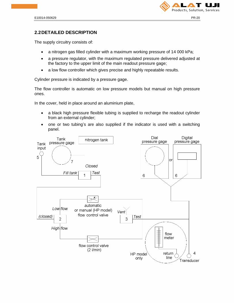
The supply circuitry consists of:
a nitrogen gas filled cylinder with a maximum working pressure of 14 000 kPa;
a pressure regulator, with the maximum regulated pressure delivered adjusted at the factory to the upper limit of the main readout pressure gage;
a low flow controller which gives precise and highly repeatable results.
Cylinder pressure is indicated by a pressure gage.
The flow controller is automatic on low pressure models but manual on high pressure ones.
In the cover, held in place around an aluminium plate,
a black high pressure flexible tubing is supplied to recharge the readout cylinder from an external cylinder;
one or two tubing’s are also supplied if the indicator is used with a switching panel.
E10014-050629 PR-20
Figure 2: PR-20 (D) (HP) circuitry
E10014-050629 PR-20
2.3 FRONT PANEL
The pressure indicator front panel comprises three valves, several connectors and two pressure gages, as shown on the following figure.
Figure 3: PR-20D HP front panel
THREE POSITION VALVE #1
“Fill tank” position is used to fill the gas cylinder.
“Test” position is used to take a reading.
“Closed” position is used during transportation.
TWO POSITION VALVE #2
“High flow” position is used to fill quickly the tubing.
“Low flow” position is used to get a constant flow of nitrogen under which conditions the transducer is read.
The position in the middle closes the circuitry and is used during transportation.
TWO POSITION VALVE #3
“Test” position is used to take a reading.
“Vent” position is used to vent the pressure line to atmosphere.
QUICK CONNECT #4
It is used to hook up the transducer pressure line to the readout unit.
QUICK CONNECT #5
It is used to hook up the internal nitrogen gas cylinder to an external recharging tank.
E10014-050629 PR-20
PRESSURE GAGE #6
It is a precision dial gage on PR-20 model or a digital one on PR-20D. It provides by direct reading the pressure of the transducer being monitored.
PRESSURE GAGE #7
It indicates the pressure in the readout nitrogen cylinder. The maximum allowable pressure is 13 700 kPa.
CONNECTOR #8 (HP model only)
It is used to connect the return pressure line from the transducer.
FINE ADJUSTMENT NEEDLE VALVE #9 (HP model only)
It is used with the flow meter in the cover to adjust the gas flow to the transducer.
2.4 CALIBRATION
A calibration data sheet is supplied with each readout unit. It enables to verify the accuracy of the pressure gage. Each gage is individually calibrated over its working range before shipment.
An example of calibration sheet is provided at the end of the manual.
3 READING PROCEDURE
If using a digital pressure gage, please refer to its own manual for its functioning.
3.1 USING A STANDARD PR-20(D)
Follow the steps below to take a reading with the pneumatic readout unit.
1. Turn valve #1 on “Closed”.
2. Turn valve #2 in mid position (closed).
3. Turn valve #3 on “Vent”.
4. Remove the brass plug from the return line leading from the transducer or insure free air circulation on return line. For model PTT-48 or PTT-316 twin nylon tubing, the return line is black.
It is very important to remove the brass plug from the return line prior to attempt any reading.
Otherwise, the pore pressure membrane could be damaged.
E10014-050629 PR-20
5. Hook up the pressure input line leading from the transducer to quick connect #4. For model PTT-48 or PTT-316 twin nylon tubing, the input line is white.
Where a switching panel is used, use the nylon tubing located in the cover to hook up the readout unit to the panel pressure input fitting.
6. Turn valve #1 and valve #3 on “Test”.
7. Turn valve #2 on “High flow”.
The pressure indicated on the pressure gage #6 increases progressively and stabilizes at the readout pressure.
The "High flow" position is used only to accelerate line pressurization during the initial reading or for long tubing runs. This initial pressurization may take up to half an hour or even more, depending on the tubing length and the pressure needed to reach the transducer’s applied pressure. Tubing over 100 m is particularly long to pressurize.
Note: If using a switching panel, the pressure line leading from it to the pressure transducer remains pressurized for subsequent readings and a shorter time is required to build up to the readout pressure. The "High flow" position should be avoided where the lines are already pressurized, as its use will result in unnecessary consumption of nitrogen.
8. Turn valve #2 on “Low flow” and wait approximately 30 to 60 seconds (more than one minute if tube length is over 30 m) until the pressure stabilizes. Read pressure on the pressure gage #6.
9. Once the reading is taken, turn valve #1 on “Closed”.
10. Disconnect the transducer from quick connect #4.
11. Turn valve #3 on “Vent”.
12. Turn valve #2 on “High flow”.
3.2 USING A HIGH PRESSURE PR-20(D) HP
Follow the steps below to take a reading with the pneumatic readout unit.
1. Turn valve #1 on “Closed”.
2. Turn valve #2 in mid position (closed).
3. Turn valve #3 on “Vent”.
E10014-050629 PR-20
4. Remove the brass plug from the return line leading from the transducer. For model PTT-48 or PTT-316 twin nylon tubing, the return line is black. Connect it to the fitting #8.
It is very important to remove the brass plug from the return line prior to attempt any reading.
Otherwise, the pore pressure membrane could be damaged.
5. Hook up the pressure input line leading from the transducer to quick connect #4. For model PTT-48 or PTT-316 twin nylon tubing, the input line is white.
Where a switching panel is used, use the two nylon tubing’s to hook up the readout unit to the panel pressure input fitting.
6. Turn valve #1 and valve #3 on “Test”.
7. Turn valve #2 on “High flow”.
The pressure indicated on the pressure gage #6 increases progressively and stabilizes at the readout pressure. The flow meter located in the cover indicates the maximum value of its scale as the high flow is adjusted in factory at 2 l/min.
The "High flow" position is used only to accelerate line pressurization during the initial reading or for long tubing runs. This initial pressurization may take up to half an hour or even more, depending on the tubing length and the pressure needed to reach the transducer’s applied pressure. Tubing over 100 m or pressures over 2 000 kPa are particularly long to pressurize.
Note: If using a switching panel, the pressure lines leading from it to the pressure transducer remain pressurized for subsequent readings and a shorter time is required to build up to the readout pressure. The "High flow" position should be avoided where the lines are already pressurized, as its use will result in unnecessary consumption of nitrogen.
8. Turn valve #2 on “Low flow”.
9. Close the fine adjustment needle valve #9 by turning it clockwise. Wait until the pressure stabilizes on the pressure gage #6 and flow drops under 50 cm³/min.
10. Open the needle valve #9 slowly by turning it counter clockwise until the flow meter shows 50 cm³/min.
11. Read pressure on the pressure gage #6.
E10014-050629 PR-20
Depending on the read pressure, the tubing can stay pressurized for next reading or not. Follow the proper procedure for ending measurement.
Reading pressure less than 700 kPa
12. Once the reading is taken, turn valve #1 on “Closed”.
13. Disconnect the transducer from quick connect #4. The tubing stays pressurized for next reading.
14. Turn valve #3 on “Vent”.
15. Turn valve #2 on “High flow”.
Reading pressure greater than 700 kPa and no switching panel used
If the transducer is connected directly on the readout unit, it is not possible because of high pressure to disconnect the connectors and let the tubing pressurized.
12. Once the reading is taken, turn valve #1 on “Closed”.
13. Turn valve #3 on “Vent”.
14. Disconnect the transducer from quick connect #4. The tubing will need to be re-pressurized for the next reading.
15. Turn valve #2 on “High flow”.
Use of a switching panel
12. Once the reading is taken, close the valve corresponding to the transducer.
13. Turn valve #1 on “Closed”.
14. Turn valve #3 on “Vent”.
15. This way, the lines between the switching panel and the readout unit can easily be disconnected and the tubing between the switching panel and the transducer stays pressurized.
16. Turn valve #2 on “High flow”.
E10014-050629 PR-20
4 MAINTENANCE
4.1 READOUT UNIT
The readout case is watertight. Avoid bumps and hits to the unit.
Keep the unit front panel clean and avoid splashing the valves and connectors. Clean the quick connects if they are clogged with mud or dust.
4.2 REFILLING GAS CYLINDER
Follow the steps below to refill the gas cylinder of the readout unit.
1. Hook up the black tubing located in the cover to quick connect #5 and to the nitrogen gas cylinder.
2. Turn valve #1 on "Fill tank" position and open VERY SLOWLY the external supply cylinder.
3. Close valve #1 when pressure gage #7 reaches 14 000 kPa.
4. Close the valve on the external supply cylinder and disconnect the refilling tubing from the cylinder.
Use only standard industrial nitrogen.
5 TROUBLESHOOTING
Keeping the readout unit clean and dry as well as a secure storage decreases its chance to fail. Be sure the gas cylinder contains enough nitrogen by checking the pressure gage #7 before beginning troubleshooting.
Instable or no reading at low pressure:
A small leak is suspected in the circuitry.
Note: A small leak may not be detected when measuring high pressure levels. It does not affect high pressure readings as well.
Bubbling sound in the circuitry:
Water comes inside the readout unit through the tubing. The transducer watertightness is suspected.
Trouble with digital pressure gage #7:
Office: Jl. Radin Inten II No. 62 Duren Sawit, Jakarta 13440 - IndonesiaWorkshop: Jl. Pahlawan Revolusi No. 22B, Jakarta 13430 - IndonesiaPhone: 021-8690 6777 (Hunting)