3.1 Installation of the PUC44-1 and PUC44-2 in a wall recess ............................................... 12 3.2 Installation of the PUC44-1 and PUC44-2 with a recessed socket ................................... 12 3.3 Installation of the PUC44-3 .............................................................................................. 13 3.4 Dismantling the PUC44-3 ................................................................................................ 14
4.1 Basic settings .................................................................................................................. 17 a) Language .................................................................................................................... 18 b) Date and time .............................................................................................................. 18 c) Time zone ................................................................................................................... 18 d) Brightness ................................................................................................................... 19 e) Screen saver ............................................................................................................... 19 f) Brightness in screen saver mode ................................................................................ 19 g) Initial view ................................................................................................................... 20 h) Change view ............................................................................................................... 20 i) Display time ................................................................................................................ 20
4.2 Inputs............................................................................................................................... 21 a) Name .......................................................................................................................... 22 b) Unit ............................................................................................................................. 22 c) Mode ........................................................................................................................... 22 d) Source ........................................................................................................................ 22 e) Source configuration ................................................................................................... 23 f) Scaling ........................................................................................................................ 24 g) Scaling configuration ................................................................................................... 24 h) Filter ............................................................................................................................ 26 i) Filter configuration ....................................................................................................... 26 j) Format ........................................................................................................................ 27 k) Decimal place ............................................................................................................. 27 l) Bar graph min./max. .................................................................................................... 27
4.3 Highlight color profiles for alarm display ........................................................................... 28 a) Mode ........................................................................................................................... 29 b) Blink period ................................................................................................................. 30 c) Min. ON time ............................................................................................................... 30
4.4 Individual alarms .............................................................................................................. 32 a) Name .......................................................................................................................... 33 b) Mode ........................................................................................................................... 33 c) Source ........................................................................................................................ 33
4.5 Source configuration for the individual alarms .................................................................. 34 a) Source ........................................................................................................................ 34 b) Level ........................................................................................................................... 35 c) Hysteresis ................................................................................................................... 35 d) ON Delay .................................................................................................................... 35 e) OFF Delay ................................................................................................................... 35 f) Min. ON time ............................................................................................................... 35 g) Min. OFF time ............................................................................................................. 35
4.6 Summary alarm configuration .......................................................................................... 35 a) Name .......................................................................................................................... 36 b) Mode ........................................................................................................................... 36 c) Source ........................................................................................................................ 36
4.7 Views ............................................................................................................................... 37 a) Name .......................................................................................................................... 37 b) Available views............................................................................................................ 37 c) Orientation of the bar graph......................................................................................... 38 d) Orientation of the chart ................................................................................................ 38 e) Line width .................................................................................................................... 39 f) Time scale ................................................................................................................... 39 g) Background ................................................................................................................. 39 h) Display channels ......................................................................................................... 39
4.8 Modbus ............................................................................................................................ 41 a) Mode ........................................................................................................................... 41 b) Baud rate .................................................................................................................... 41 c) Format ........................................................................................................................ 42 d) Address ....................................................................................................................... 42
4.9 Modbus slave settings ..................................................................................................... 42 a) Load device template .................................................................................................. 43 b) Save device template .................................................................................................. 43 c) Output list .................................................................................................................... 43 d) Available output blocks ................................................................................................ 48 e) Structure of Modbus request and response ................................................................. 49 f) Modbus error messages .............................................................................................. 50
a) Load / Save configuration ............................................................................................ 51 b) Load / Save Modbus slave template ............................................................................ 52
4.12 Information ...................................................................................................................... 52 a) Firmware update ......................................................................................................... 53 b) Export manual ............................................................................................................. 53 c) Service options............................................................................................................ 53
5 Parameterization with an Excel list ........................................................... 54
6 Technical data .......................................................................................... 56
Instruction Manual PUC 44
4
Validity and purpose of the instruction manual
This instruction manual describes the features of the PUC44-1, PUC44-2 and PUC44-3 process monitoring instruments. Improper use of these instruments or failure to follow these instructions may cause injury or damage equipment. All individuals responsible for operating these instruments must therefore be properly trained and aware of the hazards. The instruction manual, and in particular the safety precautions contained therein, must be followed carefully. Contact the manufacturer if you do not understand any part of this instruction manual. Handle this manual with care:
It must be readily available throughout the lifecycle of the instruments.
It must be provided to any individuals who assume responsibility for operating the instrument at a later date.
It must include any supplementary materials provided by the manufacturer. The manufacturer reserves the right to continue developing this instrument model without documenting such development in each individual case. The manufacturer will be happy to determine whether this manual is up-to-date.
Conformity
This device is state of the art. It complies with the legal requirements of EC directives. This is shown by the CE mark.
The manufacturer owns the copyright to this instruction manual. It contains technical data, instructions and drawings detailing the devices’ features and how to use them. It must not be copied either wholly or in part or made available to third parties.
Instruction Manual PUC 44
5
1 Safety precautions
1.1 Appropriate use
The PUC 44 is used to display process data (e.g. pressure, temperature, humidity). These process data are sent to the instrument as an electrical current (4 to 20 mA) using analog signals. Always observe the operating requirements – particularly the permissible supply voltage – indicated on the rating plate and in the “Technical data” section of this manual. The instrument may only be handled as indicated in this manual. Modifications to the instrument are prohibited. The manufacturer is not liable for damages caused by improper use or failure to follow these instructions. Violations of this type render all warranty claims null and void.
1.2 Shipping, assembly, electrical connections and start-up
During transportation, the temperature must remain within the permitted storage temperature range. Assembly and the electrical connections should only be handled by professionals. They should be given proper training and be authorized by the operator of the facility. The instrument may only be operated by appropriately trained individuals who have been authorized by the operator of the facility. Specific safety precautions are described in the individual sections of this manual. A recess in the wall must be provided at the place of installation. Alternatively, a recessed socket may be provided for the PUC44-1 and PUC44-2. See section entitled "Assembly" for detailed assembly instructions. This instrument requires no grounding.
The individual responsible for the electrical connections must be notified immediately if the instrument is damaged or if errors occur. This individual must take the instrument out of service until the error has been corrected and ensure that it cannot be used unintentionally. This instrument requires no maintenance.
Only the manufacturer may perform repairs that require the housing to be opened. The electronic components of the instrument contain environmentally hazardous materials and materials that can be recycled. The instrument must therefore be sent to a recycling plant when you no longer wish to use it. You are legally required to comply with your country's environmental codes in this area.
Instruction Manual PUC 44
6
1.4 Symbols
This instruction manual uses the following symbols to highlight important information regarding the instruments and potential hazards when operating the equipment:
WARNING! This warns you of a potential hazard that could lead to bodily injury up to and including death if the corresponding instructions are not followed.
PLEASE NOTE! This warns you of a potential hazard that could lead to significant property damage if you do not follow the corresponding instructions.
INFORMATION! This indicates information which is important for operating the instrument properly.
2 Instrument description
2.1 General functions
The PUC 44 is a microprocessor-controlled process monitoring instrument specially designed for use in clean rooms. It has four analog inputs (each 4..20 mA) for connecting any external sensors required. The processor has a high level of computing power and is thus capable of being run with a LINUX-based operating system. The instrument can therefore run several processes simultaneously (e.g. measurement, communication, visualization). The instrument presents data and dialogs on a color TFT display with a resolution of 320x240 pixels. The integrated display can show up to four signals either as a Value, Bar Graph, Chart or Needles. You can only view the course of a signal over time in "Chart" mode. You can display the signals in any way you wish, i.e. all four signals simultaneously or even just one signal occupying the full screen. The name of the measured value and the unit, the scaling of the measured value, the color assignment and filter settings can be chosen freely for each signal. In addition, there are extensive options for displaying values that exceed or fall below the limit range values. An acoustic signal is also available. This indicates a summary error message which results from any OR combination of the individual errors messages. The PUC 44 is parameterized using the menus on the touch screen integrated into the display. These menus also enable you to switch the view. The instrument is therefore simply and intuitive to operate.
Instruction Manual PUC 44
7
Once you have entered the desired configuration for one instrument, you can transfer this configuration to other PUC 44 devices using a USB stick. The PUC 44 has a Modbus RTU interface for connecting it to a building management system. All the current values from the PUC 44 can be read via the Modbus. The PUC 44 is available in three versions for different installation scenarios: with an aluminium front panel (PUC44-1), a stainless steel front panel with screw fastening (PUC44-2) or a stainless steel front panel with magnetic fastening (PUC44-3).
2.2 Operation of the touch screen monitor
Never operate the touch screen monitor using objects with sharp edges (e.g. knives, scissors, needles, wire, nails, screws etc.). We highly recommend using a stylus made of plastic or some other soft material with rounded edges. You should also protect the instrument display against aggressive substances and very high and low temperatures as these can cause damage.
2.3 Using a USB mouse and/or keyboard
You can operate the PUC 44 using a USB mouse if you do not wish to use the touch screen. A mouse cursor will appear on the screen as soon as you connect a mouse to the USB port. Now you can move the mouse cursor over the screen in the familiar way. Click with the left mouse button to display the keys used to switch the view and configure the instrument. You can click the other keys using the left or right mouse buttons. You can also connect a USB keyboard. However, this can only be used to enter data in a text field. Alternatively, you can connect a combined mouse-keyboard solution (incl. wireless versions) which shares the USB port. To do this, plug the wireless transmitter USB stick into the PUC 44. Now you can move the battery operated wireless mouse and keyboard around freely. You can then, for example, activate a text field using the mouse and write in it using the keyboard. Although you can use USB hubs, the PUC 44 will only detect the first device on the hub.
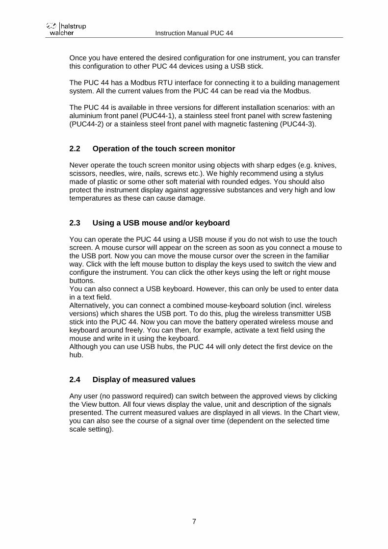
2.4 Display of measured values
Any user (no password required) can switch between the approved views by clicking the View button. All four views display the value, unit and description of the signals presented. The current measured values are displayed in all views. In the Chart view, you can also see the course of a signal over time (dependent on the selected time scale setting).
Instruction Manual PUC 44
8
Example of the Value view:
Example of the Bar Graph view:
Example of the Chart view:
Instruction Manual PUC 44
9
Example of the Needles view:
Three different display sizes are available for the Value and Needles views. The display size selected is based on the number of deactivated window areas:
Number of deactivated window areas
Display size
0..1 small
2 medium
3 large
Touch the screen anywhere to display the buttons used for changing the view and configuration. These are located in the lower section of the screen.
You can also open the configuration menu for a displayed channel directly. To do this, press the screen in the area of the required channel and hold for 3-4 seconds.
2.5 Signalling of alarm status
The PUC 44 distinguishes between two types of error:
Sensor error
Permissible input range exceeded
A sensor error results when the input signal current falls below the lowest or rises
above the highest permissible level. You can adjust the parameters for these values, see section "Source configuration" under "Parameterization Inputs" for a detailed explanation.
Instruction Manual PUC 44
10
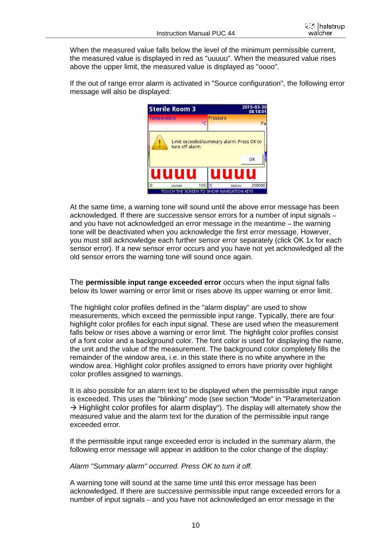
When the measured value falls below the level of the minimum permissible current, the measured value is displayed in red as "uuuuu". When the measured value rises above the upper limit, the measured value is displayed as "oooo". If the out of range error alarm is activated in "Source configuration", the following error message will also be displayed:
At the same time, a warning tone will sound until the above error message has been acknowledged. If there are successive sensor errors for a number of input signals –
and you have not acknowledged an error message in the meantime – the warning tone will be deactivated when you acknowledge the first error message. However, you must still acknowledge each further sensor error separately (click OK 1x for each sensor error). If a new sensor error occurs and you have not yet acknowledged all the old sensor errors the warning tone will sound once again.
The permissible input range exceeded error occurs when the input signal falls
below its lower warning or error limit or rises above its upper warning or error limit. The highlight color profiles defined in the "alarm display" are used to show measurements, which exceed the permissible input range. Typically, there are four highlight color profiles for each input signal. These are used when the measurement falls below or rises above a warning or error limit. The highlight color profiles consist of a font color and a background color. The font color is used for displaying the name, the unit and the value of the measurement. The background color completely fills the remainder of the window area, i.e. in this state there is no white anywhere in the window area. Highlight color profiles assigned to errors have priority over highlight color profiles assigned to warnings. It is also possible for an alarm text to be displayed when the permissible input range is exceeded. This uses the "blinking" mode (see section "Mode" in "Parameterization
Highlight color profiles for alarm display"). The display will alternately show the
measured value and the alarm text for the duration of the permissible input range exceeded error. If the permissible input range exceeded error is included in the summary alarm, the following error message will appear in addition to the color change of the display: Alarm "Summary alarm" occurred. Press OK to turn it off. A warning tone will sound at the same time until this error message has been acknowledged. If there are successive permissible input range exceeded errors for a number of input signals – and you have not acknowledged an error message in the
Instruction Manual PUC 44
11
meantime – the warning tone will be deactivated when you acknowledge the first error message and the error message will disappear. If a permissible input range exceeded error changes to a sensor error, the signal for the sensor error has priority over the signal for the permissible input range exceeded error. The highlight color profiles will change automatically if the input signal rises above the lower warning or error limit or falls below the upper warning or error limit.
2.6 Pin assignment
The following connections are available in the upper section of the rear side of the housing:
Terminal Port designation Use
1 24V DC - Supply GND
2 24V DC + Supply +24V
3 RS485 A+ Modbus A+
4 RS485 B- Modbus B-
5 RS485 GND Modbus GND
6 IN1 Hi Measurement input 1, High
7 IN1 Lo Measurement input 1, Low
8 IN2 Hi Measurement input 2, High
9 IN2 Lo Measurement input 2, Low
10 IN3 Hi Measurement input 3, High
11 IN3 Lo Measurement input 3, Low
12 IN4 Hi Measurement input 4, High
13 IN4 Lo Measurement input 4, Low
The measurement inputs are galvanically separated from each other and the other electronics in the instrument. A measurement input will not be permanently damaged if it is mistakenly connected to the supply voltage.
If sensors using two-wire technology are connected, they must be
provided with a separate 24V power supply. The following connections are required: - Positive contact of the sensor with the +24V of the separate supply - Negative contact of the sensor with the "High" measurement input of the PUC 44 - "Low" measurement input of the PUC 44 with GND of the separate supply instead of the separate power supply, you can also use the +24V supply of terminals 1+2. However, there is then no galvanic separation.
Ensure that the instrument is disconnected from the supply voltage before making any connections!
Low down at the rear of the instrument, you will also find a USB port. This can be used to connect a USB stick (for loading and backing up parameterization data) or for a USB mouse or keyboard or a mouse-keyboard combination (see also section 2.3).
Instruction Manual PUC 44
12
2.7 Cleaning
Do not clean the instrument using solvents. Use warm water and a little washing-up liquid or ethyl or isopropyl alcohol if particularly dirty.
The use of other cleaning materials can permanently damage the housing.
2.8 Measures for preventing incorrect readings
Industrial plants and installations can cause significant interference to measurements. Ensure that suitable measures are in place so the instrument is able to function correctly. Follow the recommendations below to prevent incorrect readings:
Avoid laying the signalling and transmission cables parallel to supply voltage cables and cables for controlling inductive loads (e.g. contactors). These cables should cross at right angles.
Contactor coils and inductive loads should be protected against interference, e.g. by using an RC circuit.
We recommend the use of shielded signal cables. Signal cable shielding should only be grounded at one end of the shielded cable.
If interference is induced by magnetic fields, we recommend the use of twisted pair signal cables. In this case it is then also necessary to use a cable of this type for serial RS485 connections.
If the supply voltage is causing interference, we recommend the use of suitable interference filters. Please note that the connection between the filter and the instrument should be kept as short as possible and that the metal housing of the filter should be grounded with the largest possible cross-section. Cables connected to the filter must not run parallel to the signal cables.
3 Assembly
3.1 Installation of the PUC44-1 and PUC44-2 in a wall recess
First create a recess in the wall at the place of installation using the hole template provided (approx. 115mm wide and 135mm high) and make four drill holes (approx. Ø 4.3mm if you intend to use the M4 round head screws supplied). However, you can also use wood screws, with anchors if necessary. Insert the PUC 44 into the recess and fasten it in position, e.g. with the round head screws and M4 hexagon nuts also provided. The round head screws are 25mm long so the max. wall thickness should be around 15mm.
3.2 Installation of the PUC44-1 and PUC44-2 with a recessed socket
The 9601.0188 recessed socket is available for installation of the instruments in a masonry wall. This socket is plastered into the wall. In this case the installation template provided is not required.
Instruction Manual PUC 44
13
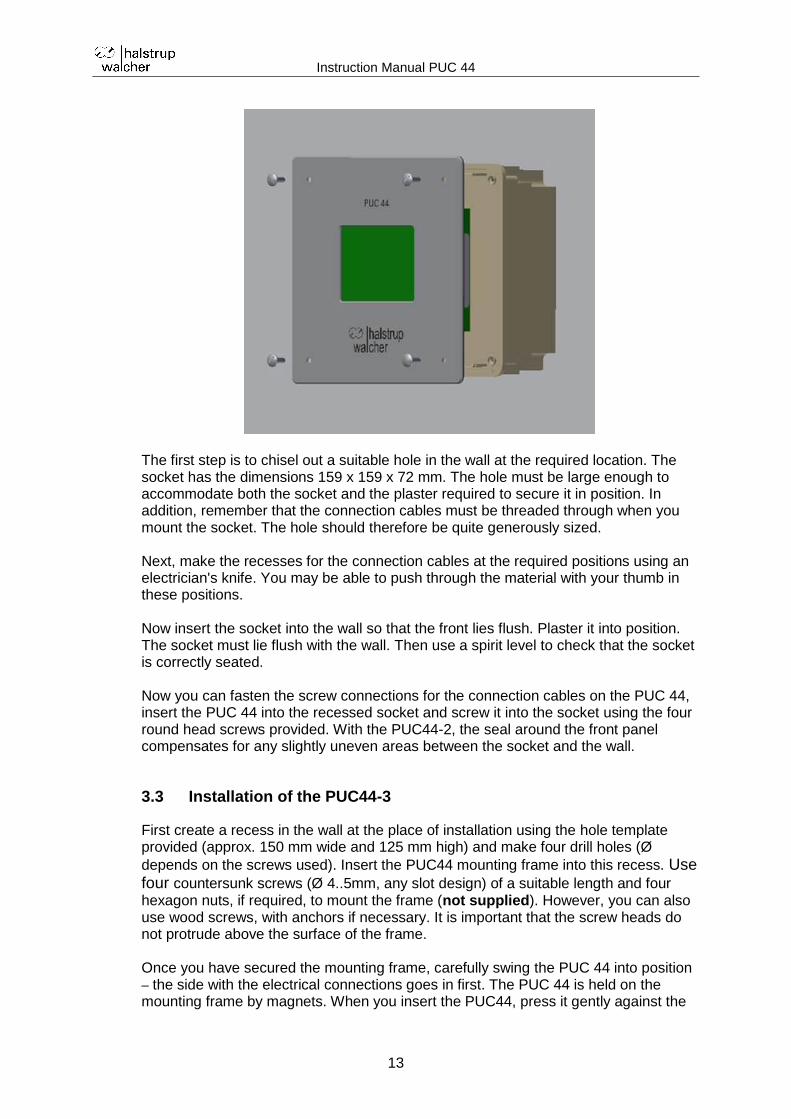
The first step is to chisel out a suitable hole in the wall at the required location. The socket has the dimensions 159 x 159 x 72 mm. The hole must be large enough to accommodate both the socket and the plaster required to secure it in position. In addition, remember that the connection cables must be threaded through when you mount the socket. The hole should therefore be quite generously sized. Next, make the recesses for the connection cables at the required positions using an electrician's knife. You may be able to push through the material with your thumb in these positions. Now insert the socket into the wall so that the front lies flush. Plaster it into position. The socket must lie flush with the wall. Then use a spirit level to check that the socket is correctly seated. Now you can fasten the screw connections for the connection cables on the PUC 44, insert the PUC 44 into the recessed socket and screw it into the socket using the four round head screws provided. With the PUC44-2, the seal around the front panel compensates for any slightly uneven areas between the socket and the wall.
3.3 Installation of the PUC44-3
First create a recess in the wall at the place of installation using the hole template provided (approx. 150 mm wide and 125 mm high) and make four drill holes (Ø
depends on the screws used). Insert the PUC44 mounting frame into this recess. Use four countersunk screws (Ø 4..5mm, any slot design) of a suitable length and four hexagon nuts, if required, to mount the frame (not supplied). However, you can also use wood screws, with anchors if necessary. It is important that the screw heads do not protrude above the surface of the frame. Once you have secured the mounting frame, carefully swing the PUC 44 into position – the side with the electrical connections goes in first. The PUC 44 is held on the mounting frame by magnets. When you insert the PUC44, press it gently against the
Instruction Manual PUC 44
14
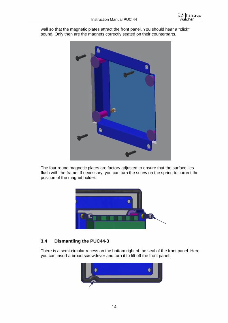
wall so that the magnetic plates attract the front panel. You should hear a "click" sound. Only then are the magnets correctly seated on their counterparts.
The four round magnetic plates are factory adjusted to ensure that the surface lies flush with the frame. If necessary, you can turn the screw on the spring to correct the position of the magnet holder:
3.4 Dismantling the PUC44-3
There is a semi-circular recess on the bottom right of the seal of the front panel. Here, you can insert a broad screwdriver and turn it to lift off the front panel:
Instruction Manual PUC 44
15
4 Parameterization
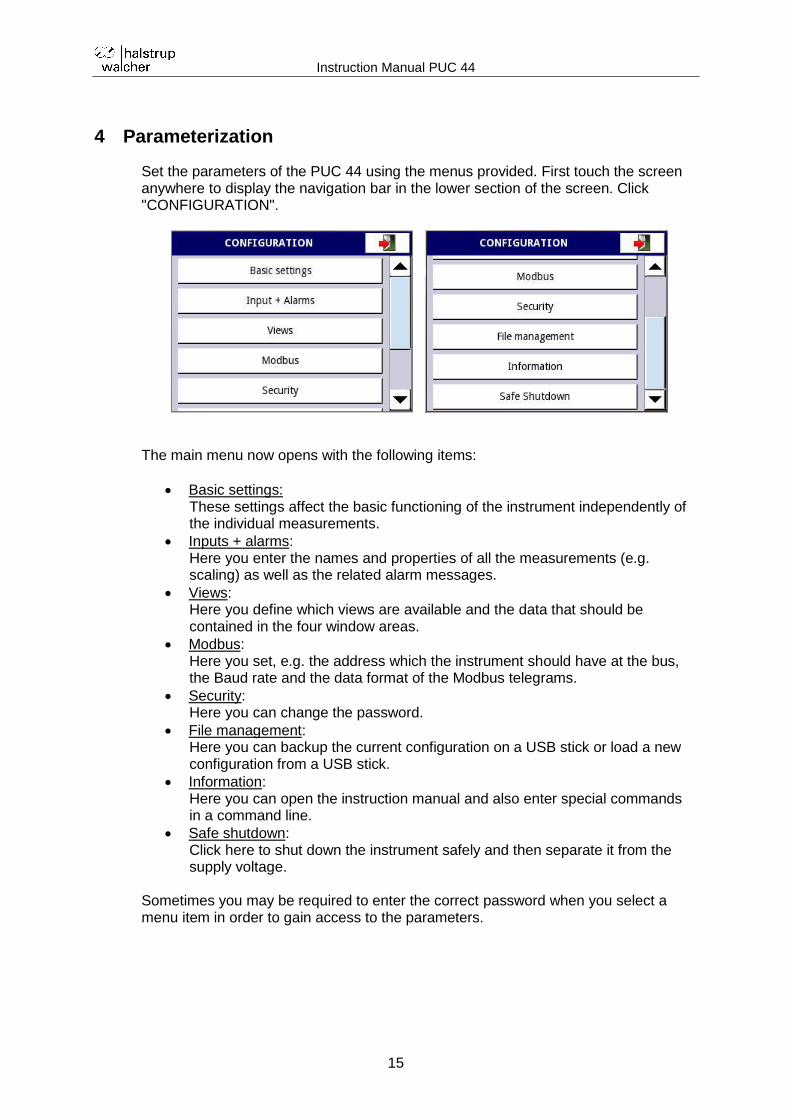
Set the parameters of the PUC 44 using the menus provided. First touch the screen anywhere to display the navigation bar in the lower section of the screen. Click "CONFIGURATION".
The main menu now opens with the following items:
Basic settings: These settings affect the basic functioning of the instrument independently of the individual measurements.
Inputs + alarms: Here you enter the names and properties of all the measurements (e.g. scaling) as well as the related alarm messages.
Views: Here you define which views are available and the data that should be contained in the four window areas.
Modbus: Here you set, e.g. the address which the instrument should have at the bus, the Baud rate and the data format of the Modbus telegrams.
Security: Here you can change the password.
File management: Here you can backup the current configuration on a USB stick or load a new configuration from a USB stick.
Information: Here you can open the instruction manual and also enter special commands in a command line.
Safe shutdown: Click here to shut down the instrument safely and then separate it from the supply voltage.
Sometimes you may be required to enter the correct password when you select a menu item in order to gain access to the parameters.
Instruction Manual PUC 44
16
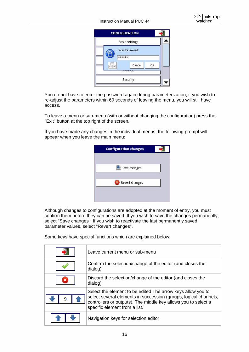
You do not have to enter the password again during parameterization; if you wish to re-adjust the parameters within 60 seconds of leaving the menu, you will still have access. To leave a menu or sub-menu (with or without changing the configuration) press the "Exit" button at the top right of the screen. If you have made any changes in the individual menus, the following prompt will appear when you leave the main menu:
Although changes to configurations are adopted at the moment of entry, you must confirm them before they can be saved. If you wish to save the changes permanently, select "Save changes". If you wish to reactivate the last permanently saved parameter values, select "Revert changes". Some keys have special functions which are explained below:
Leave current menu or sub-menu
Confirm the selection/change of the editor (and closes the dialog)
Discard the selection/change of the editor (and closes the dialog)
Select the element to be edited The arrow keys allow you to select several elements in succession (groups, logical channels, controllers or outputs). The middle key allows you to select a specific element from a list.
Navigation keys for selection editor
Instruction Manual PUC 44
17
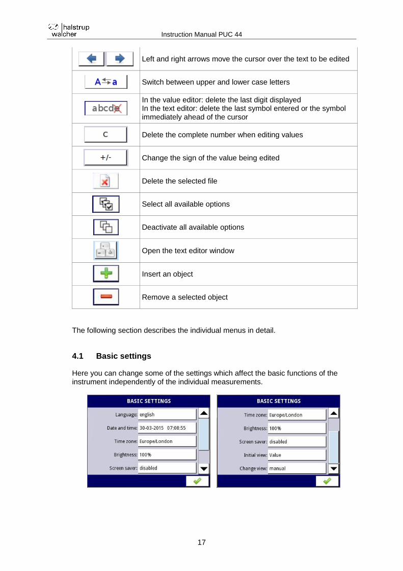
Left and right arrows move the cursor over the text to be edited
Switch between upper and lower case letters
In the value editor: delete the last digit displayed In the text editor: delete the last symbol entered or the symbol immediately ahead of the cursor
Delete the complete number when editing values
Change the sign of the value being edited
Delete the selected file
Select all available options
Deactivate all available options
Open the text editor window
Insert an object
Remove a selected object
The following section describes the individual menus in detail.
4.1 Basic settings
Here you can change some of the settings which affect the basic functions of the instrument independently of the individual measurements.
Instruction Manual PUC 44
18
a) Language
The following languages are available:
German
English
French
Italian
Spanish
The language setting affects all the texts permanently stored in the firmware (i.e. the menu system) but not the descriptions entered during parameterization. Nor does it take into account other country-specific properties (e.g. date formats).
b) Date and time
Here you enter the current date and time. These appear at the top right of every view. They are also used in the "Chart" view.
c) Time zone
Select a continent and city to set the correct time zone for your location.
Instruction Manual PUC 44
19
d) Brightness
Here you can adjust the backlighting for the display (in 20% increments).
e) Screen saver
Set the time at which the brightness will be reduced when the touch screen is no longer being used (1 min, 5 min, 10 min, 30 min or disabled).
f) Brightness in screen saver mode
Here you can adjust the backlighting for the display (in 20% increments) when the touch screen is not being operated.
Instruction Manual PUC 44
20
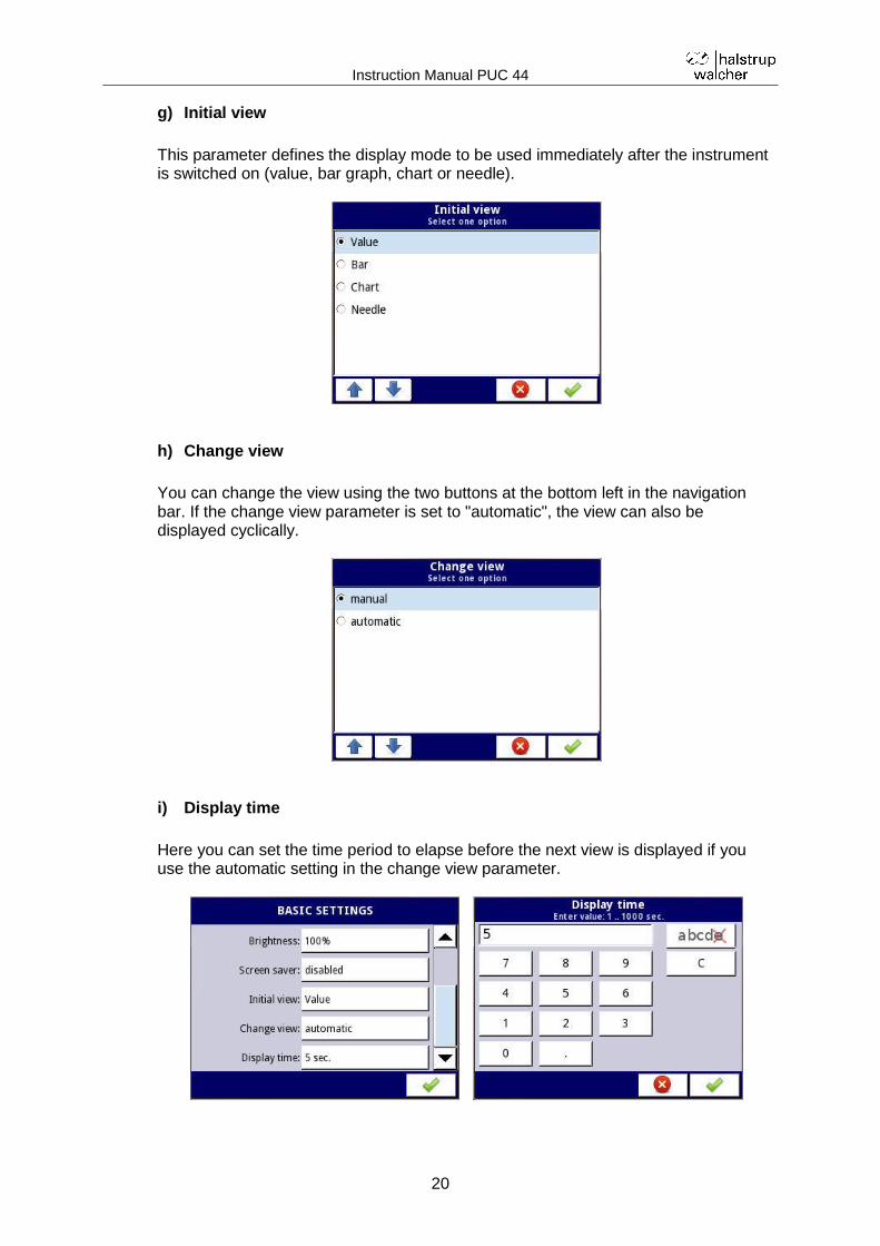
g) Initial view
This parameter defines the display mode to be used immediately after the instrument is switched on (value, bar graph, chart or needle).
h) Change view
You can change the view using the two buttons at the bottom left in the navigation bar. If the change view parameter is set to "automatic", the view can also be displayed cyclically.
i) Display time
Here you can set the time period to elapse before the next view is displayed if you use the automatic setting in the change view parameter.
Instruction Manual PUC 44
21
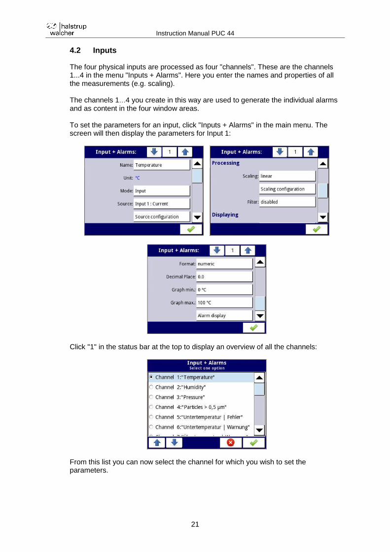
4.2 Inputs
The four physical inputs are processed as four "channels". These are the channels 1...4 in the menu "Inputs + Alarms". Here you enter the names and properties of all the measurements (e.g. scaling). The channels 1…4 you create in this way are used to generate the individual alarms and as content in the four window areas. To set the parameters for an input, click "Inputs + Alarms" in the main menu. The screen will then display the parameters for Input 1:
Click "1" in the status bar at the top to display an overview of all the channels:
From this list you can now select the channel for which you wish to set the parameters.
Instruction Manual PUC 44
22
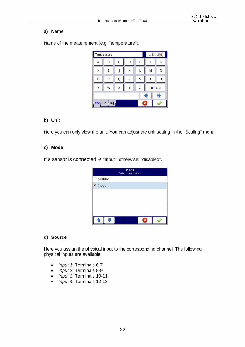
a) Name
Name of the measurement (e.g. "temperature").
b) Unit
Here you can only view the unit. You can adjust the unit setting in the "Scaling" menu.
c) Mode
If a sensor is connected "Input"; otherwise: "disabled".
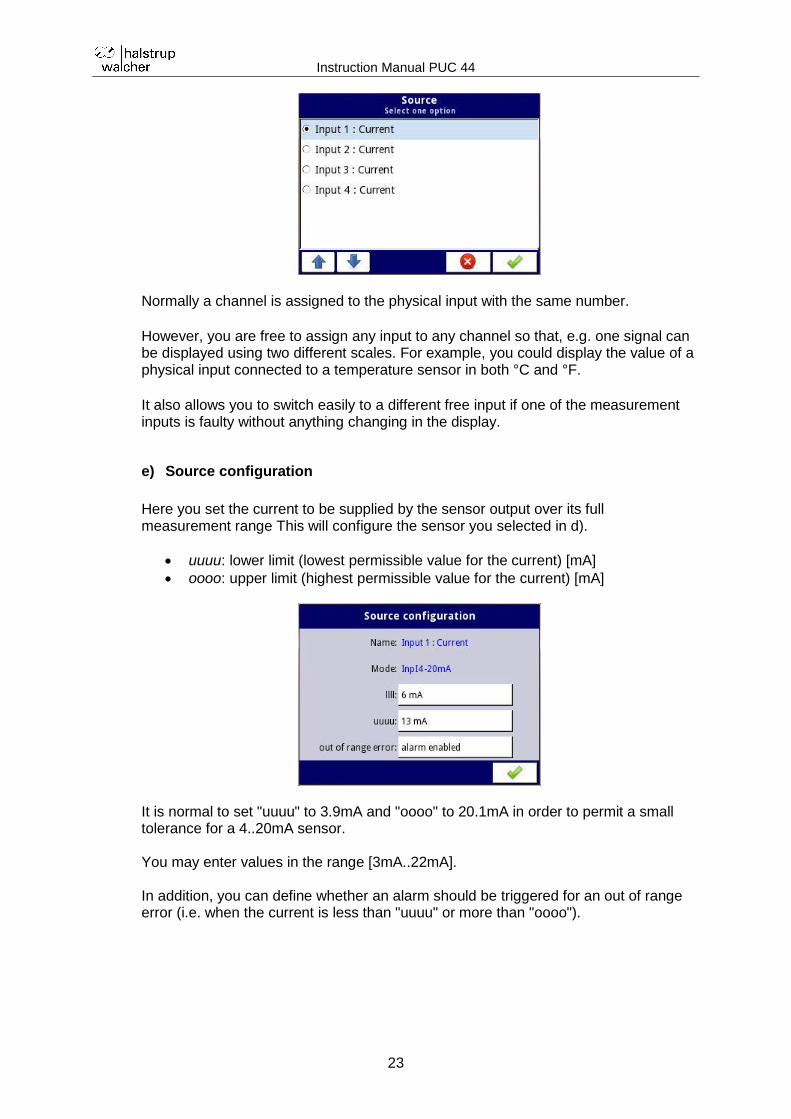
d) Source
Here you assign the physical input to the corresponding channel. The following physical inputs are available:
Input 1: Terminals 6-7
Input 2: Terminals 8-9
Input 3: Terminals 10-11
Input 4: Terminals 12-13
Instruction Manual PUC 44
23
Normally a channel is assigned to the physical input with the same number. However, you are free to assign any input to any channel so that, e.g. one signal can be displayed using two different scales. For example, you could display the value of a physical input connected to a temperature sensor in both °C and °F. It also allows you to switch easily to a different free input if one of the measurement inputs is faulty without anything changing in the display.
e) Source configuration
Here you set the current to be supplied by the sensor output over its full measurement range This will configure the sensor you selected in d).
uuuu: lower limit (lowest permissible value for the current) [mA]
oooo: upper limit (highest permissible value for the current) [mA]
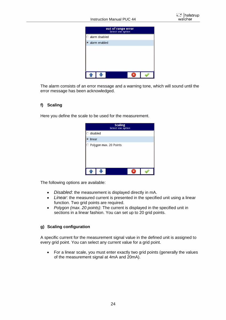
It is normal to set "uuuu" to 3.9mA and "oooo" to 20.1mA in order to permit a small tolerance for a 4..20mA sensor. You may enter values in the range [3mA..22mA]. In addition, you can define whether an alarm should be triggered for an out of range error (i.e. when the current is less than "uuuu" or more than "oooo").
Instruction Manual PUC 44
24
The alarm consists of an error message and a warning tone, which will sound until the error message has been acknowledged.
f) Scaling
Here you define the scale to be used for the measurement.
The following options are available:
Disabled: the measurement is displayed directly in mA.
Linear: the measured current is presented in the specified unit using a linear
function. Two grid points are required.
Polygon (max. 20 points): The current is displayed in the specified unit in sections in a linear fashion. You can set up to 20 grid points.
g) Scaling configuration
A specific current for the measurement signal value in the defined unit is assigned to every grid point. You can select any current value for a grid point.
For a linear scale, you must enter exactly two grid points (generally the values of the measurement signal at 4mA and 20mA).
Instruction Manual PUC 44
25
For a polygon, the number of grid points can vary between 2 and 20. A linear function is set between the defined points. Example:
You can add further grid points by selecting "Add point":
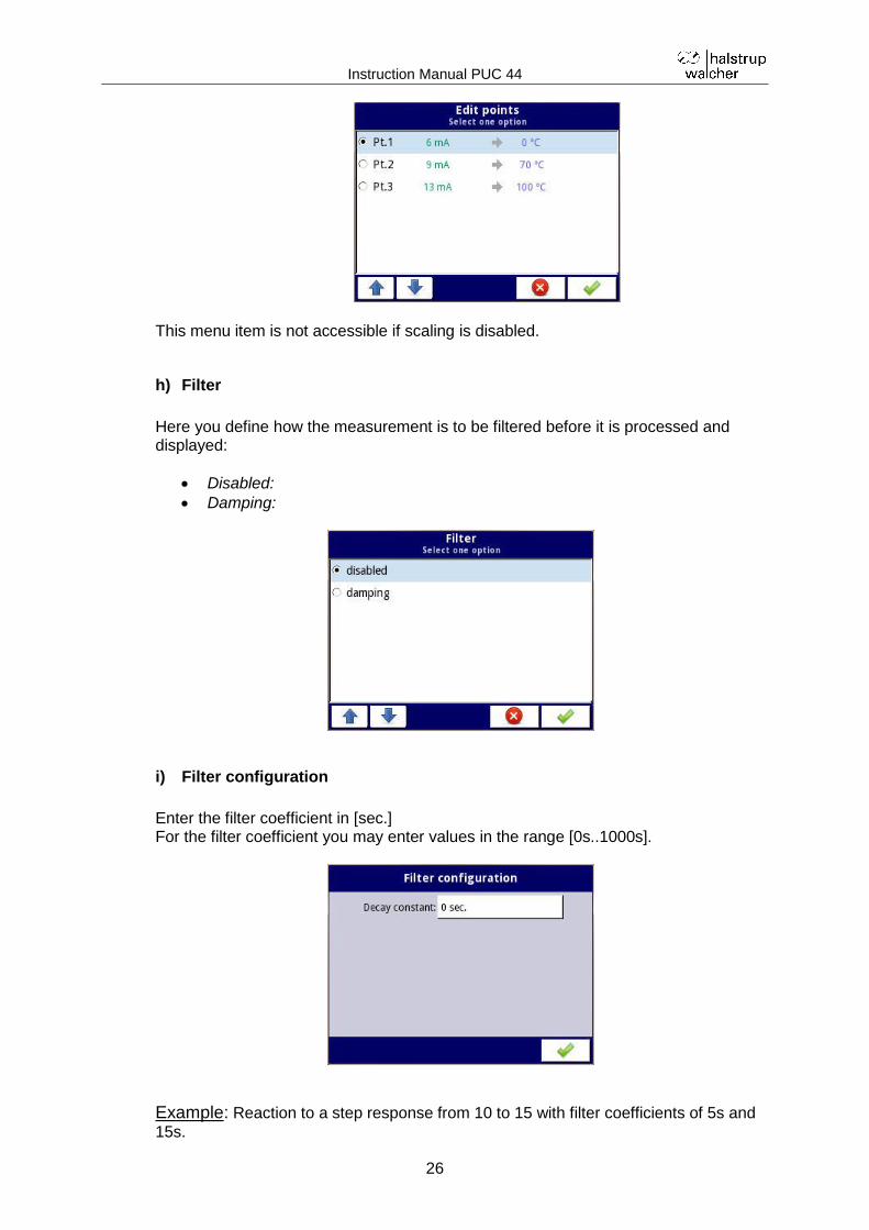
You can find a clear depiction of the grid points in the sub-menu "Edit points" by clicking the middle button in the top line of the grid point selection.
Instruction Manual PUC 44
26
This menu item is not accessible if scaling is disabled.
h) Filter
Here you define how the measurement is to be filtered before it is processed and displayed:
Disabled:
Damping:
i) Filter configuration
Enter the filter coefficient in [sec.] For the filter coefficient you may enter values in the range [0s..1000s].
Example: Reaction to a step response from 10 to 15 with filter coefficients of 5s and
15s.
Instruction Manual PUC 44
27
This menu item is not accessible if the filter function is disabled.
j) Format
The display format is permanently set to "numeric" and cannot be changed.
k) Decimal place
Here you set the number of decimal places ("Decimal places") to be used in displaying the measurement signal. The following options are available:
0 (no decimal places)
0.0 (one decimal place)
0.00 (two decimal places)
0.000 (three decimal places)
0.0000 (four decimal places)
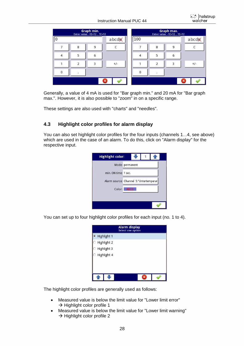
l) Bar graph min./max.
Here you define the measured values which correspond to the left and right edges of the bar graph.
Instruction Manual PUC 44
28
Generally, a value of 4 mA is used for "Bar graph min." and 20 mA for "Bar graph max.". However, it is also possible to "zoom" in on a specific range. These settings are also used with "charts" and "needles".
4.3 Highlight color profiles for alarm display
You can also set highlight color profiles for the four inputs (channels 1…4, see above) which are used in the case of an alarm. To do this, click on "Alarm display" for the respective input.
You can set up to four highlight color profiles for each input (no. 1 to 4).
The highlight color profiles are generally used as follows:
Measured value is below the limit value for "Lower limit error" Highlight color profile 1
Measured value is below the limit value for "Lower limit warning" Highlight color profile 2
Instruction Manual PUC 44
29
Measured value is above the limit value for "Upper limit warning" Highlight color profile 3
Measured value is above the limit value for "Upper limit error" Highlight color profile 4
A highlight color profile is only ever used in the window area of the corresponding measurement input. The following section describes the individual parameters for a highlight color profile in detail.
a) Mode
Here you set the way that the defined colors are used in the case of a permissible input range exceeded error:
Disabled: Highlight color profiles are not used.
Permanent: The display color changes for the duration of the permissible input range exceeded error. The measured value continues to be updated continuously.
Blinking: For the duration of permissible input range exceeded error, the display will alternately show the measured value and an alarm text. The measured value continues to be updated continuously. The color change is only used for the alarm text, the measured value display is unchanged.
Instruction Manual PUC 44
30
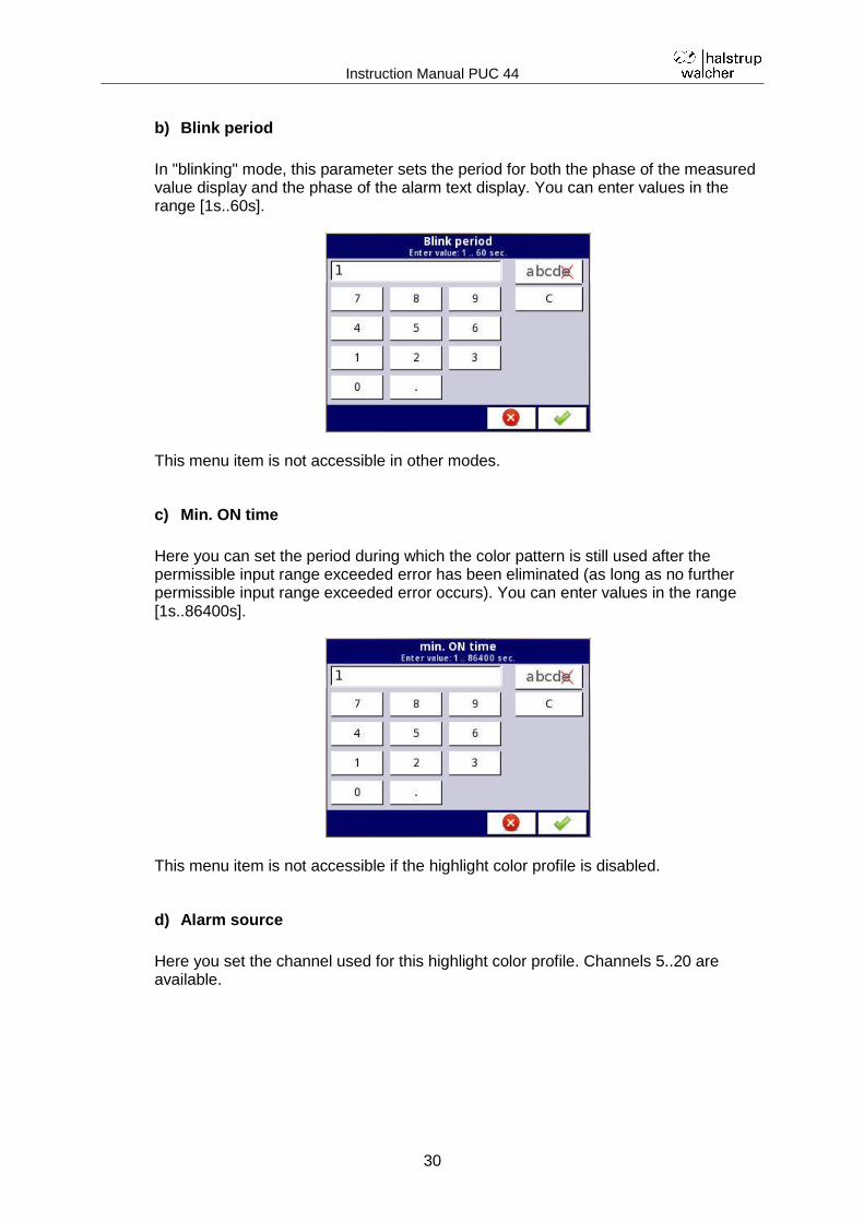
b) Blink period
In "blinking" mode, this parameter sets the period for both the phase of the measured value display and the phase of the alarm text display. You can enter values in the range [1s..60s].
This menu item is not accessible in other modes.
c) Min. ON time
Here you can set the period during which the color pattern is still used after the permissible input range exceeded error has been eliminated (as long as no further permissible input range exceeded error occurs). You can enter values in the range [1s..86400s].
This menu item is not accessible if the highlight color profile is disabled.
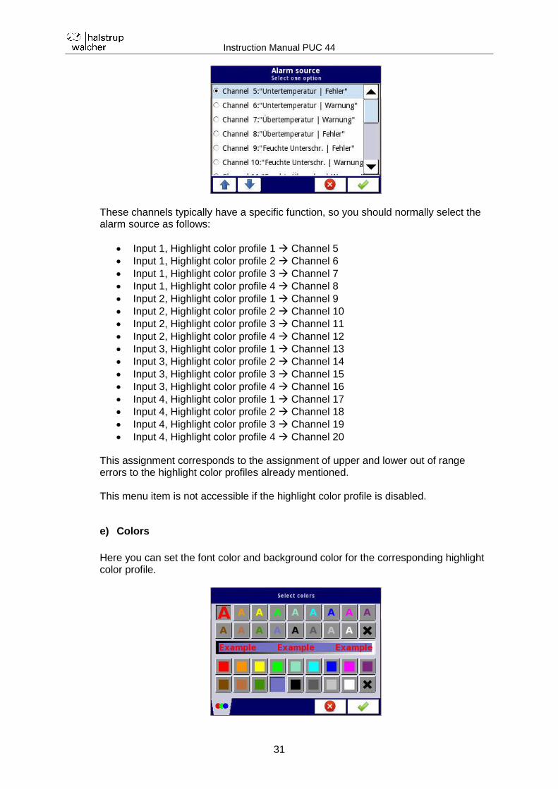
d) Alarm source
Here you set the channel used for this highlight color profile. Channels 5..20 are available.
Instruction Manual PUC 44
31
These channels typically have a specific function, so you should normally select the alarm source as follows:
Input 1, Highlight color profile 1 Channel 5
Input 1, Highlight color profile 2 Channel 6
Input 1, Highlight color profile 3 Channel 7
Input 1, Highlight color profile 4 Channel 8
Input 2, Highlight color profile 1 Channel 9
Input 2, Highlight color profile 2 Channel 10
Input 2, Highlight color profile 3 Channel 11
Input 2, Highlight color profile 4 Channel 12
Input 3, Highlight color profile 1 Channel 13
Input 3, Highlight color profile 2 Channel 14
Input 3, Highlight color profile 3 Channel 15
Input 3, Highlight color profile 4 Channel 16
Input 4, Highlight color profile 1 Channel 17
Input 4, Highlight color profile 2 Channel 18
Input 4, Highlight color profile 3 Channel 19
Input 4, Highlight color profile 4 Channel 20 This assignment corresponds to the assignment of upper and lower out of range errors to the highlight color profiles already mentioned. This menu item is not accessible if the highlight color profile is disabled.
e) Colors
Here you can set the font color and background color for the corresponding highlight color profile.
Instruction Manual PUC 44
32
The following colors are available:
red
orange
yellow
green
blue-green
turquoise
blue
pale violet
deep violet
brown
light brown
dark green
pale blue
black
dark grey
light grey
white
no color Select the font color in the upper section of the window and the background color in the lower section. In "blinking" mode, this is also where you enter the alarm text:
When an alarm is triggered, the respective alarm text appears in the corresponding window area. The text is aligned to the right margin. If you wish the text to be centered, you can do this by adding spaces to the alarm text.
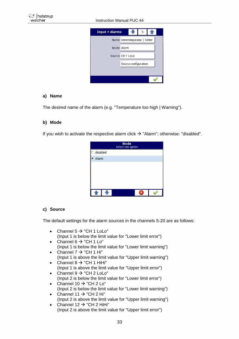
4.4 Individual alarms
You can activate the 16 possible individual alarms as channels 5...20 in the menu "Inputs + Alarms". Select an alarm to specify its properties.
Instruction Manual PUC 44
33
a) Name
The desired name of the alarm (e.g. "Temperature too high | Warning").
b) Mode
If you wish to activate the respective alarm click "Alarm"; otherwise: "disabled".
c) Source
The default settings for the alarm sources in the channels 5-20 are as follows:
Channel 5 "CH 1 LoLo" (Input 1 is below the limit value for "Lower limit error")
Channel 6 "CH 1 Lo" (Input 1 is below the limit value for "Lower limit warning")
Channel 7 "CH 1 Hi" (Input 1 is above the limit value for "Upper limit warning")
Channel 8 "CH 1 HiHi" (Input 1 is above the limit value for "Upper limit error")
Channel 9 "CH 2 LoLo" (Input 2 is below the limit value for "Lower limit error")
Channel 10 "CH 2 Lo" (Input 2 is below the limit value for "Lower limit warning")
Channel 11 "CH 2 Hi" (Input 2 is above the limit value for "Upper limit warning")
Channel 12 "CH 2 HiHi" (Input 2 is above the limit value for "Upper limit error")
Instruction Manual PUC 44
34
Channel 13 "CH 3 LoLo" (Input 3 is below the limit value for "Lower limit error")
Channel 14 "CH 3 Lo" (Input 3 is below the limit value for "Lower limit warning")
Channel 15 "CH 3 Hi" (Input 3 is above the limit value for "Upper limit warning")
Channel 16 "CH 3 HiHi" (Input 3 is above the limit value for "Upper limit error")
Channel 17 "CH 4 LoLo" (Input 4 is below the limit value for "Lower limit error")
Channel 18 "CH 4 Lo" (Input 4 is below the limit value for "Lower limit warning")
Channel 19 "CH 4 Hi" (Input 4 is above the limit value for "Upper limit warning")
Channel 20 "CH 4 HiHi" (Input 4 is above the limit value for "Upper limit error")
Do not change this default assignment.
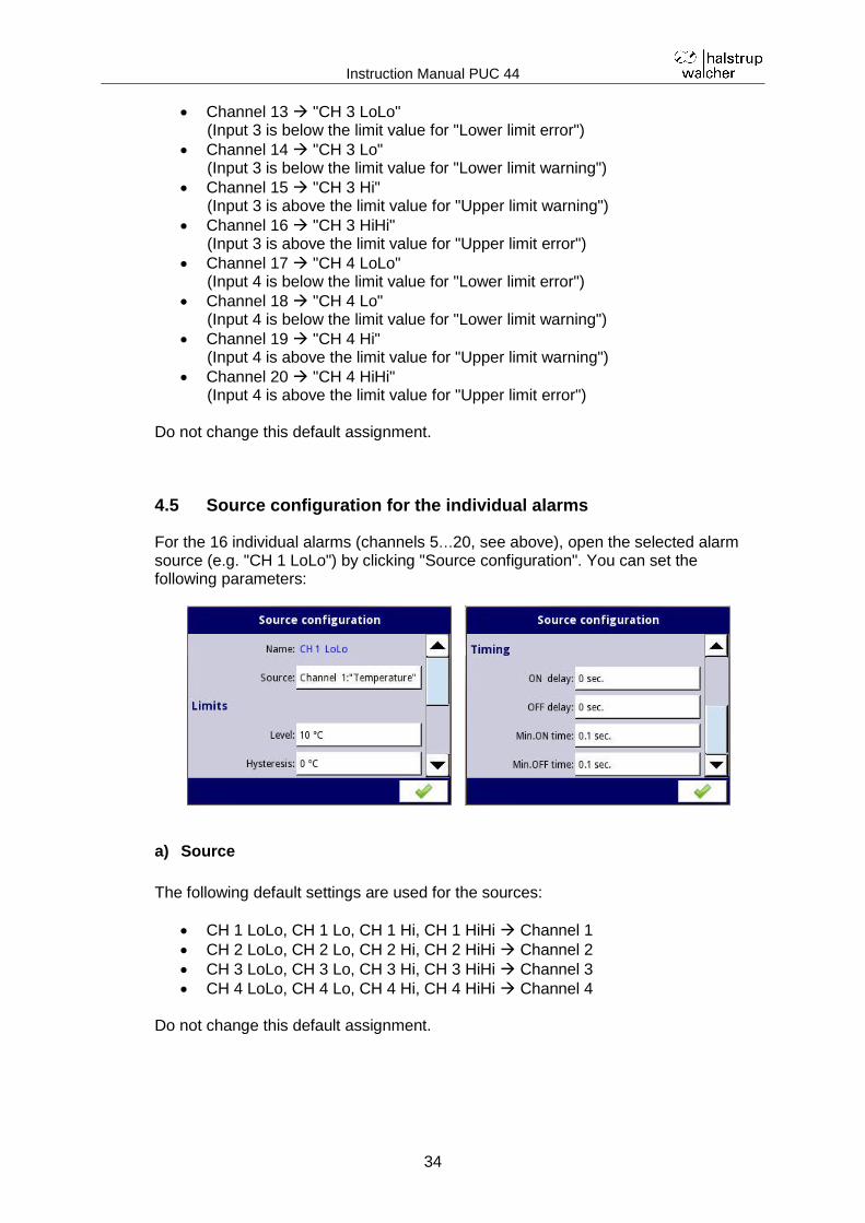
4.5 Source configuration for the individual alarms
For the 16 individual alarms (channels 5…20, see above), open the selected alarm source (e.g. "CH 1 LoLo") by clicking "Source configuration". You can set the following parameters:
a) Source
The following default settings are used for the sources:
CH 1 LoLo, CH 1 Lo, CH 1 Hi, CH 1 HiHi Channel 1
CH 2 LoLo, CH 2 Lo, CH 2 Hi, CH 2 HiHi Channel 2
CH 3 LoLo, CH 3 Lo, CH 3 Hi, CH 3 HiHi Channel 3
CH 4 LoLo, CH 4 Lo, CH 4 Hi, CH 4 HiHi Channel 4 Do not change this default assignment.
Instruction Manual PUC 44
35
b) Level
Here you enter the upper or lower limit value at which the respective alarm will be triggered.
c) Hysteresis
Hysteresis is used to prevent repeated triggering of the alarm if the measurement signal moves with a small amplitude over a longer period around the limit value set in "Level". Depending on the type of alarm, the following relationships apply: 1) For all alarm sources "LoLo" and "Lo":
The alarm is triggered when the signal falls below the limit value [Level - Hysteresis].
The alarm is reset when the signal rises above the limit value [Level + Hysteresis].
2) For all alarm sources "HiHi" and "Hi":
The alarm is triggered when the signal rises above the limit value [Level + Hysteresis].
The alarm is reset when the signal falls below the limit value [Level - Hysteresis].
d) ON Delay
Period of time that the permissible input range exceeded error must persist in order for the alarm to be triggered.
e) OFF Delay
Period of time that the input must remain within the limit values in order for the alarm to be reset.
f) Min. ON time
Minimum time that an alarm must remain on once triggered.
g) Min. OFF time
Minimum time that a reset alarm must remain off before it can be triggered again.
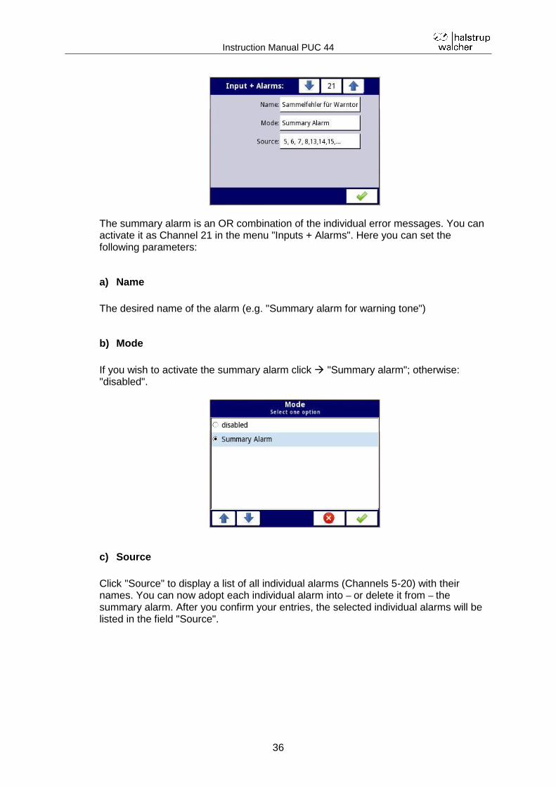
4.6 Summary alarm configuration
The summary alarm is used to generate acoustic signals when one or more individual alarms is triggered. The warning tone continues to sound until you acknowledge a corresponding warning message on the display.
Instruction Manual PUC 44
36
The summary alarm is an OR combination of the individual error messages. You can activate it as Channel 21 in the menu "Inputs + Alarms". Here you can set the following parameters:
a) Name
The desired name of the alarm (e.g. "Summary alarm for warning tone")
b) Mode
If you wish to activate the summary alarm click "Summary alarm"; otherwise: "disabled".
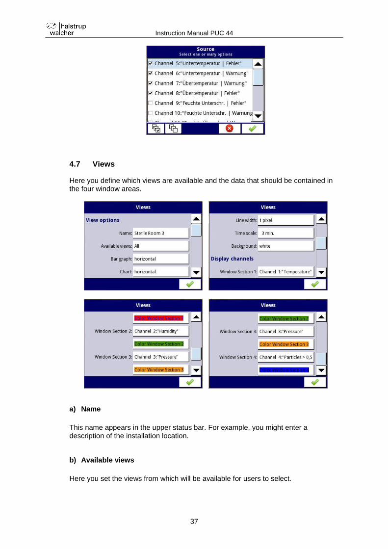
c) Source
Click "Source" to display a list of all individual alarms (Channels 5-20) with their names. You can now adopt each individual alarm into – or delete it from – the summary alarm. After you confirm your entries, the selected individual alarms will be listed in the field "Source".
Instruction Manual PUC 44
37
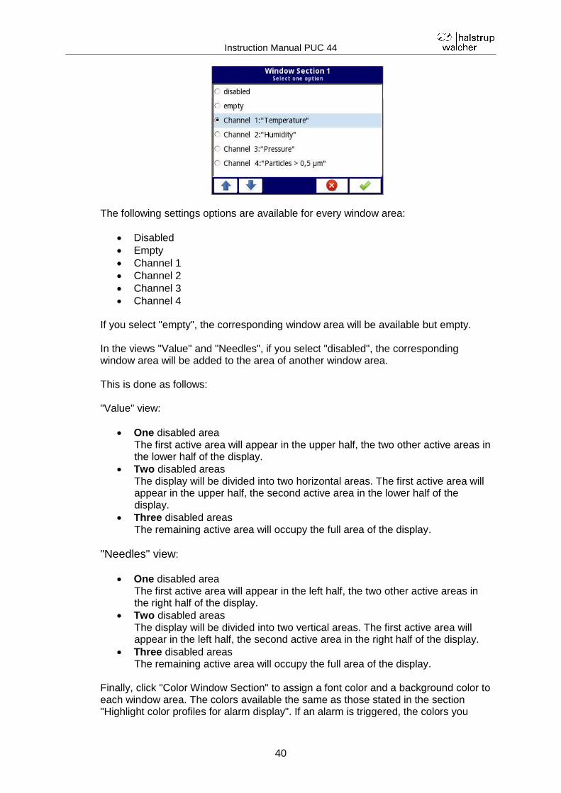
4.7 Views
Here you define which views are available and the data that should be contained in the four window areas.
a) Name
This name appears in the upper status bar. For example, you might enter a description of the installation location.
b) Available views
Here you set the views from which will be available for users to select.
Instruction Manual PUC 44
38
The following views are available:
Value
Bar graph
Chart
Needles
c) Orientation of the bar graph
The bar graph can be oriented either horizontally or vertically.
d) Orientation of the chart
The chart can be oriented either horizontally (time scale running from left to right) or vertically (time scale runs from bottom to top).
Instruction Manual PUC 44
39
e) Line width
The line width is permanently set to "1 pixel" and cannot be changed (only affects the "chart" view).
f) Time scale
Here you can set the period of time over which the measured values are visible (only affects the "chart" view).
The following values are possible:
19 s
48 s
95 s
3 min
6 min
12 min
30 min
60 min
2 h
4 h
8 h
16 h
24 h
3 d
7 d
g) Background
You can set the background for the whole display to white or black.
h) Display channels
The display is divided into four window areas which can also be combined. Here you enter which of the channels 1..4 should be displayed in the respective window areas.
Instruction Manual PUC 44
40
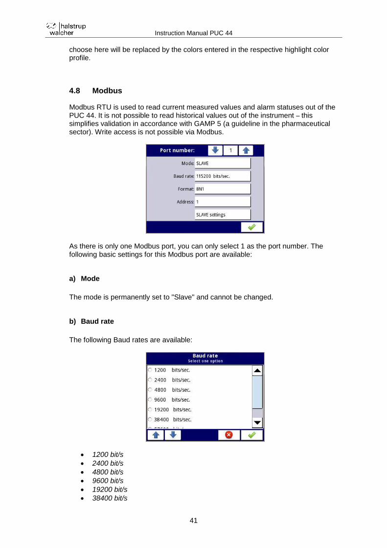
The following settings options are available for every window area:
Disabled
Empty
Channel 1
Channel 2
Channel 3
Channel 4 If you select "empty", the corresponding window area will be available but empty. In the views "Value" and "Needles", if you select "disabled", the corresponding window area will be added to the area of another window area. This is done as follows: "Value" view:
One disabled area The first active area will appear in the upper half, the two other active areas in the lower half of the display.
Two disabled areas The display will be divided into two horizontal areas. The first active area will appear in the upper half, the second active area in the lower half of the display.
Three disabled areas The remaining active area will occupy the full area of the display.
"Needles" view:
One disabled area The first active area will appear in the left half, the two other active areas in the right half of the display.
Two disabled areas The display will be divided into two vertical areas. The first active area will appear in the left half, the second active area in the right half of the display.
Three disabled areas The remaining active area will occupy the full area of the display.
Finally, click "Color Window Section" to assign a font color and a background color to each window area. The colors available the same as those stated in the section "Highlight color profiles for alarm display". If an alarm is triggered, the colors you
Instruction Manual PUC 44
41
choose here will be replaced by the colors entered in the respective highlight color profile.
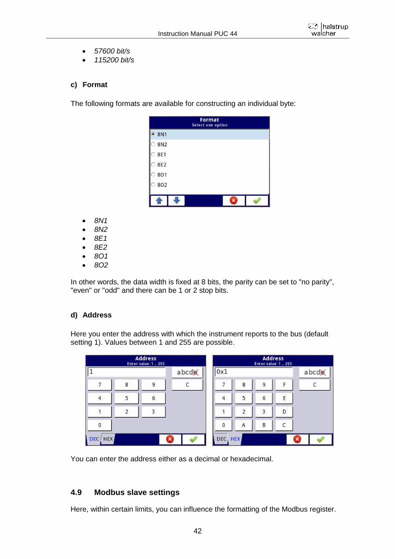
4.8 Modbus
Modbus RTU is used to read current measured values and alarm statuses out of the PUC 44. It is not possible to read historical values out of the instrument – this simplifies validation in accordance with GAMP 5 (a guideline in the pharmaceutical sector). Write access is not possible via Modbus.
As there is only one Modbus port, you can only select 1 as the port number. The following basic settings for this Modbus port are available:
a) Mode
The mode is permanently set to "Slave" and cannot be changed.
b) Baud rate
The following Baud rates are available:
1200 bit/s
2400 bit/s
4800 bit/s
9600 bit/s
19200 bit/s
38400 bit/s
Instruction Manual PUC 44
42
57600 bit/s
115200 bit/s
c) Format
The following formats are available for constructing an individual byte:
8N1
8N2
8E1
8E2
8O1
8O2 In other words, the data width is fixed at 8 bits, the parity can be set to "no parity", "even" or "odd" and there can be 1 or 2 stop bits.
d) Address
Here you enter the address with which the instrument reports to the bus (default setting 1). Values between 1 and 255 are possible.
You can enter the address either as a decimal or hexadecimal.
4.9 Modbus slave settings
Here, within certain limits, you can influence the formatting of the Modbus register.
Instruction Manual PUC 44
43
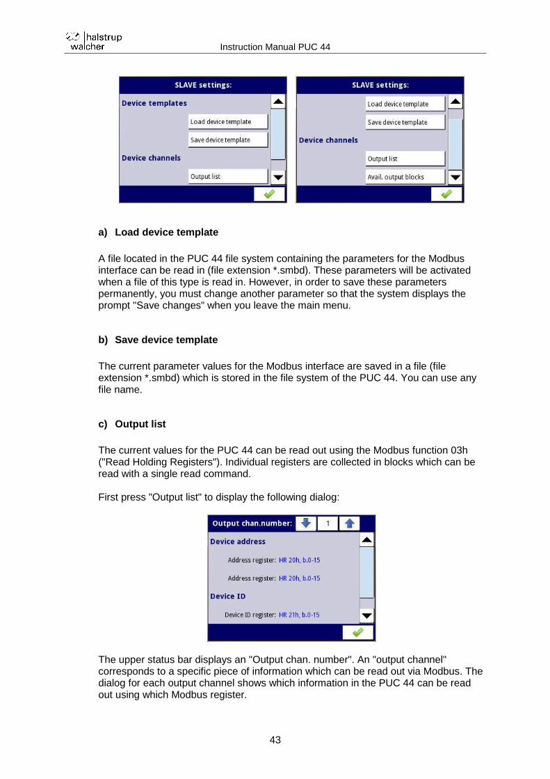
a) Load device template
A file located in the PUC 44 file system containing the parameters for the Modbus interface can be read in (file extension *.smbd). These parameters will be activated when a file of this type is read in. However, in order to save these parameters permanently, you must change another parameter so that the system displays the prompt "Save changes" when you leave the main menu.
b) Save device template
The current parameter values for the Modbus interface are saved in a file (file extension *.smbd) which is stored in the file system of the PUC 44. You can use any file name.
c) Output list
The current values for the PUC 44 can be read out using the Modbus function 03h ("Read Holding Registers"). Individual registers are collected in blocks which can be read with a single read command. First press "Output list" to display the following dialog:
The upper status bar displays an "Output chan. number". An "output channel" corresponds to a specific piece of information which can be read out via Modbus. The dialog for each output channel shows which information in the PUC 44 can be read out using which Modbus register.
Instruction Manual PUC 44
44
Output channel number 1 is displayed first. Output channel 1 contains the device address and number. These can be read out using the 16-bit registers 20h and 21h. Click "1" in the status bar at the top to display an overview of all the output channels:
Output channels > 1 contain so-called "logical channels". The logical channels ("LogChan") 1…4 are the 4 measurement inputs, LogChan 5…20 are the 16 individual alarms and LogChan 21 is the summary alarm. LogChan 22 is required internally for acknowledging alarms, "CalibrationOutEntry" is used by the manufacturer to calibrate the inputs. The possible range of values from LogChan 5…21 is restricted as follows: 0 Alarm inactive 1 Alarm active When you select a logical channel, its properties are displayed as follows:
The output channel number (shown in the upper status bar) of a logical channel is the number of this logical channel plus 1. The value register (e.g. 200h/201h for LogChan 1) always contains 32-bit values. The status register (e.g. 202h for LogChan 1) and the decimal point register (e.g. 203h for LogChan 1) are always 16 bits wide. The value registers are implemented as two 16-bit registers by default. These are read separately or with a block read command and combined into a 32-bit value in the master. However, for the registers 200h..251h it is also possible to read out the complete 32-bit value from the first value register (200h for LogChan 1). In this case, the second register (201h for LogChan 1) is not required. Here, the first value register must be declared as a 32-bit register. You do this by pressing the number of the corresponding value register in the dialog above. The properties of this value register will then appear:
Instruction Manual PUC 44
45
In the menu item "32-bit reading", select "one 32-bit register". The following options are available for "32-bit reading":
"Two 16-bit registers" (default)
"One 32-bit register" The default data format setting of the value register for the registers 200h…251h is floating point ("32 bit, float"). For this register, you can change the following data format settings in the menu item "Data format":
32 bit, signed
32 bit, unsigned
32 bit, float (default)
32 bit, BCD The value register settings for the registers 400h…451h are as follows and cannot be changed:
"32 bit reading" setting fixed to "two 16 bit registers"
Instruction Manual PUC 44
46
"Data format" setting fixed to "32 bit, signed"
Thus, by default, the values from the value registers 200h…251h can be read out as a floating point number and from the value registers 400h…451h as integers.
The floating point numbers are formatted in accordance with the IEEE754 standard. In the floating point format, the values are displayed with the highest possible degree of precision. The format "Integer 32" always displays values with the same precision depending on the position of the decimal point. For example, if the decimal point is set to 0.0, the format Int32 gives the
integer value of a floating point register value multiplied by 10 (e.g. floating
point register = 1.2345 decimal point = "0.0" gives the integer value = 12, decimal point = "0.000" gives the integer value 1234).
Instruction Manual PUC 44
47
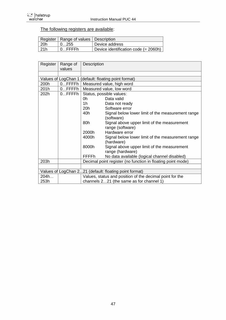
The following registers are available:
Register Range of values Description
20h 0…255 Device address
21h 0…FFFFh Device identification code (= 2060h)
Register Range of values
Description
Values of LogChan 1 (default: floating point format)
200h 0…FFFFh Measured value, high word
201h 0…FFFFh Measured value, low word
202h 0…FFFFh Status, possible values: 0h
1h 20h 40h 80h 2000h 4000h 8000h FFFFh
Data valid Data not ready Software error Signal below lower limit of the measurement range (software) Signal above upper limit of the measurement range (software) Hardware error Signal below lower limit of the measurement range (hardware) Signal above upper limit of the measurement range (hardware) No data available (logical channel disabled)
203h Decimal point register (no function in floating point mode)
Values of LogChan 2...21 (default: floating point format)
204h… 253h
Values, status and position of the decimal point for the channels 2…21 (the same as for channel 1)
Instruction Manual PUC 44
48
Register Range of values
Description
Values of LogChan 1 (integer format)
400h 0…FFFFh Measured value, high word (without decimal point)
401h 0…FFFFh Measured value, low word (without decimal point)
402h 0…FFFFh Status, possible values: 0h
1h 20h 40h 80h 2000h 4000h 8000h FFFFh
Data valid Data not ready Software error Signal below lower limit of the measurement range (software) Signal above upper limit of the measurement range (software) Hardware error Signal below lower limit of the measurement range (hardware) Signal above upper limit of the measurement range (hardware) No data available (logical channel disabled)
403h 0…6 Decimal point register (position of the decimal point)
Values of LogChan 2...21 (integer format)
404h… 453h
Values, status and position of the decimal point for the channels 2…21 (the same as for channel 1)
d) Available output blocks
Here you can see how the individual registers are summarized during read accesses.
HR 200h - 257h Values can be formatted freely (default setting is as float)
HR 400h - 457h Values as integers
HR FFFBh - FFFFh Additional information for the manufacturer
Instruction Manual PUC 44
49
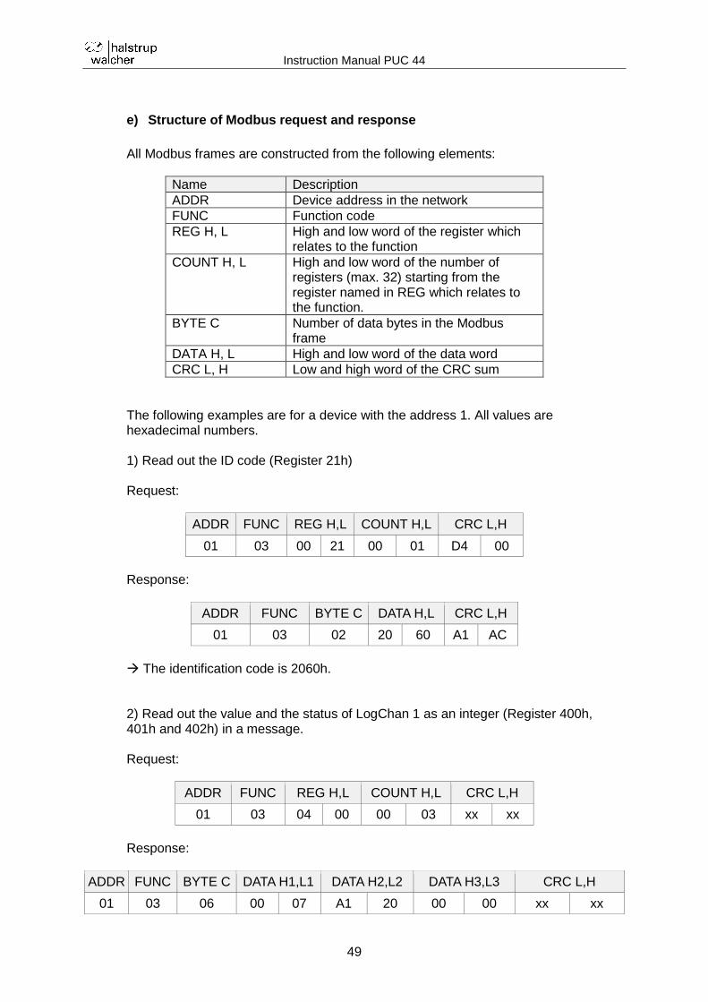
e) Structure of Modbus request and response
All Modbus frames are constructed from the following elements:
Name Description
ADDR Device address in the network
FUNC Function code
REG H, L High and low word of the register which relates to the function
COUNT H, L High and low word of the number of registers (max. 32) starting from the register named in REG which relates to the function.
BYTE C Number of data bytes in the Modbus frame
DATA H, L High and low word of the data word
CRC L, H Low and high word of the CRC sum
The following examples are for a device with the address 1. All values are hexadecimal numbers. 1) Read out the ID code (Register 21h) Request:
ADDR FUNC REG H,L COUNT H,L CRC L,H
01 03 00 21 00 01 D4 00
Response:
ADDR FUNC BYTE C DATA H,L CRC L,H
01 03 02 20 60 A1 AC
The identification code is 2060h. 2) Read out the value and the status of LogChan 1 as an integer (Register 400h, 401h and 402h) in a message. Request:
ADDR FUNC REG H,L COUNT H,L CRC L,H
01 03 04 00 00 03 xx xx
Response:
ADDR FUNC BYTE C DATA H1,L1 DATA H2,L2 DATA H3,L3 CRC L,H
01 03 06 00 07 A1 20 00 00 xx xx
Instruction Manual PUC 44
50
The value of LogChan 1 is 0007A120h (= 500000), the status is 00h ( data valid).
f) Modbus error messages
If an error occurs during reading or writing, the device will return the Modbus frame with an error code (in accordance with the Modbus protocol). The error codes have the following meanings:
01h: invalid function (only function 03 is available)
02h: invalid register address
03h: invalid data value
The Modbus protocol is not completely implemented in the device. Only the functions described above are available.
4.10 Security
To protect the device against unintentional or unauthorized changes to its settings, the user can enable a single layer of password protection. The user is then required to enter a password in order to confirm his identity as an administrator before accessing configuration functions or device data. You can set the password in the "Security" menu.
The password is stored in the device configuration and a copy is transferred together with the configuration file when this is copied.
Instruction Manual PUC 44
51
4.11 File management
You can use this menu to manage the transfer of files to and from USB sticks.
USB stick requirements:
The stick must not exceed the maximum power consumption of 100mA. If necessary, use an additional USB hub with a separate power supply for data carriers with larger capacities.
The data carrier must be formatted for Windows as FAT (not FAT32).
Files to be imported must not be saved in subfolders.
a) Load / Save configuration
The functions "Load configuration" and "Save configuration" are used to transfer files (file extension *.pcfg). These contain the following information:
Basic settings
Settings for the logical channels
Modbus settings To load a configuration file, select the configuration file on the USB stick. The following prompt will then appear "Overwrite device configuration?":
After you have confirmed the prompt, the data from the USB stick will be activated immediately and permanently stored in the device (this is why you will not see the prompt "Save changes" once again when you leave the main menu). When you save a configuration file to a USB stick, all the current active values will be written into the file.
Instruction Manual PUC 44
52
b) Load / Save Modbus slave template
The functions "Load Modbus slave template" and "Save Modbus slave template" are used to transfer files with information about the data format of the individual holding registers. When you "save" a template, a Modbus slave template already located in the file system of the PUC 44 will be saved on a USB stick. You must have first generated
this file using the command "Save device template" (see section "Modbus slave
settings" "Save device template"). In the file system of the PUC 44, these files have the file extension *.smbd. On the USB stick they have the file extension *.pscfg. When you "load" a template, a Modbus slave template located on a USB stick (file extension *.pscfg) will be copied to the file system of the PUC 44. Here this file will
appear with the file extension *.smbd. However, you must first activate the settings from this file using the command "Load device template" (see section
"Modbus slave settings" "Load device template").
The information about the data format of the individual holding registers is also stored in the general configuration file. The Modbus slave template is thus a subset of the overall configuration.
Configurations or Modbus slave templates can be transferred between the device and the data carrier once the USB stick has been connected to the device. If you wish to load files, the Flash memory symbol will appear in the window with the available configurations or the Modbus slave templates with the file extension *.pcfg or *.pscfg. Please note that the file names are defined by the user. Backup settings using the button "Save configuration" or "Save Modbus slave template". A window opens showing the files already available which can be overwritten. Alternatively, you can use the text editor to define the name of a new configuration file. After a short time, the data will be stored in the Flash memory.
4.12 Information
In this menu you can access technical information and the instruction manual.
Instruction Manual PUC 44
53
a) Firmware update
New firmware is installed via USB.
b) Export manual
The instruction manuals stored in the device in PDF format (incl. those in languages not currently activated) can be saved to a USB stick.
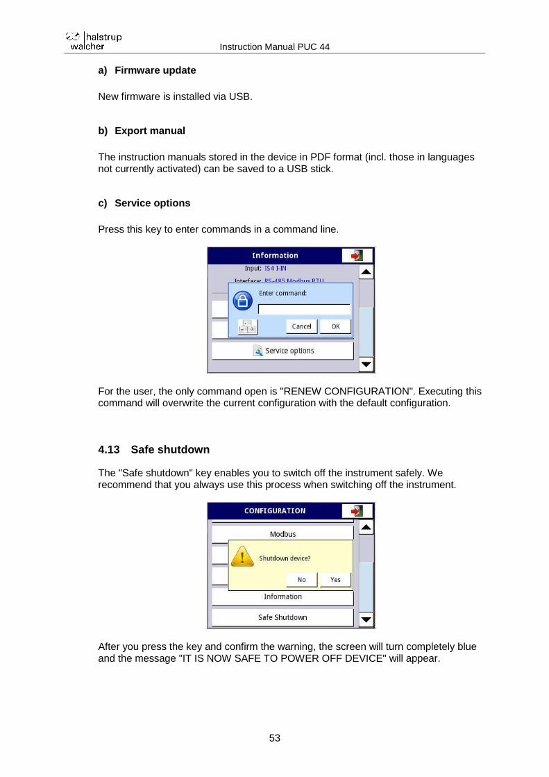
c) Service options
Press this key to enter commands in a command line.
For the user, the only command open is "RENEW CONFIGURATION". Executing this command will overwrite the current configuration with the default configuration.
4.13 Safe shutdown
The "Safe shutdown" key enables you to switch off the instrument safely. We recommend that you always use this process when switching off the instrument.
After you press the key and confirm the warning, the screen will turn completely blue and the message "IT IS NOW SAFE TO POWER OFF DEVICE" will appear.
Instruction Manual PUC 44
54
5 Parameterization with an Excel list
You can use the Excel list "PUC 44 template for parameterization" to set the parameters using a PC. You can then send the completed Excel list to halstrup-walcher together with your order for a PUC 44. The instrument is then supplied with the requested parameterization. The individual fields of the Excel list are already completed with default values. Consequently, you need only change those fields for which the required values differ from the default values. The following field types are available:
Character strings (e.g. for the name and unit of the measurement)
Number values (e.g. for scaling the measurement)
Check boxes The Excel spreadsheet also contains plausibility checks. Example: You have to enter the upper limit value for the current of the first measurement input:
If the value you enter is too high (e.g. 25 mA), the following error message will appear:
In some cases, entries from other fields will be adopted, e.g. names of measurement inputs and the corresponding units.
Instruction Manual PUC 44
55
Here is a section of an Excel list:
After it has been checked by halstrup-walcher, the parameterization will be given a unique number and the customer can refer to this from now on whenever placing orders.
Instruction Manual PUC 44
56
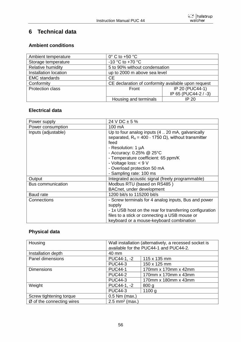
6 Technical data
Ambient conditions Ambient temperature 0° C to +50 °C
Storage temperature -10 °C to +70 °C
Relative humidity 5 to 90% without condensation
Installation location up to 2000 m above sea level
EMC standards CE
Conformity CE declaration of conformity available upon request
Protection class Front IP 20 (PUC44-1) IP 65 (PUC44-2 / -3)
Housing and terminals IP 20
Electrical data Power supply 24 V DC ± 5 %
Power consumption 100 mA
Inputs (adjustable) Up to four analog inputs (4 .. 20 mA, galvanically separated, Ra = 400 ‐ 1750 Ω), without transmitter feed - Resolution: 1 µA - Accuracy: 0.25% @ 25°C - Temperature coefficient: 65 ppm/K - Voltage loss: < 9 V - Overload protection 50 mA - Sampling rate: 100 ms
Output Integrated acoustic signal (freely programmable)
Bus communication Modbus RTU (based on RS485 ) BACnet, under development
Baud rate 1200 bit/s to 115200 bit/s
Connections - Screw terminals for 4 analog inputs, Bus and power supply - 1x USB host on the rear for transferring configuration files to a stick or connecting a USB mouse or keyboard or a mouse-keyboard combination
Physical data Housing Wall installation (alternatively, a recessed socket is
available for the PUC44-1 and PUC44-2.
Installation depth 40 mm
Panel dimensions PUC44-1, -2 115 x 135 mm
PUC44-3 150 x 125 mm
Dimensions PUC44-1 170mm x 170mm x 42mm
PUC44-2 170mm x 170mm x 43mm
PUC44-3 170mm x 180mm x 43mm
Weight PUC44-1, -2 800 g
PUC44-3 1100 g
Screw tightening torque 0.5 Nm (max.)
Ø of the connecting wires 2.5 mm² (max.)
Instruction Manual PUC 44
57
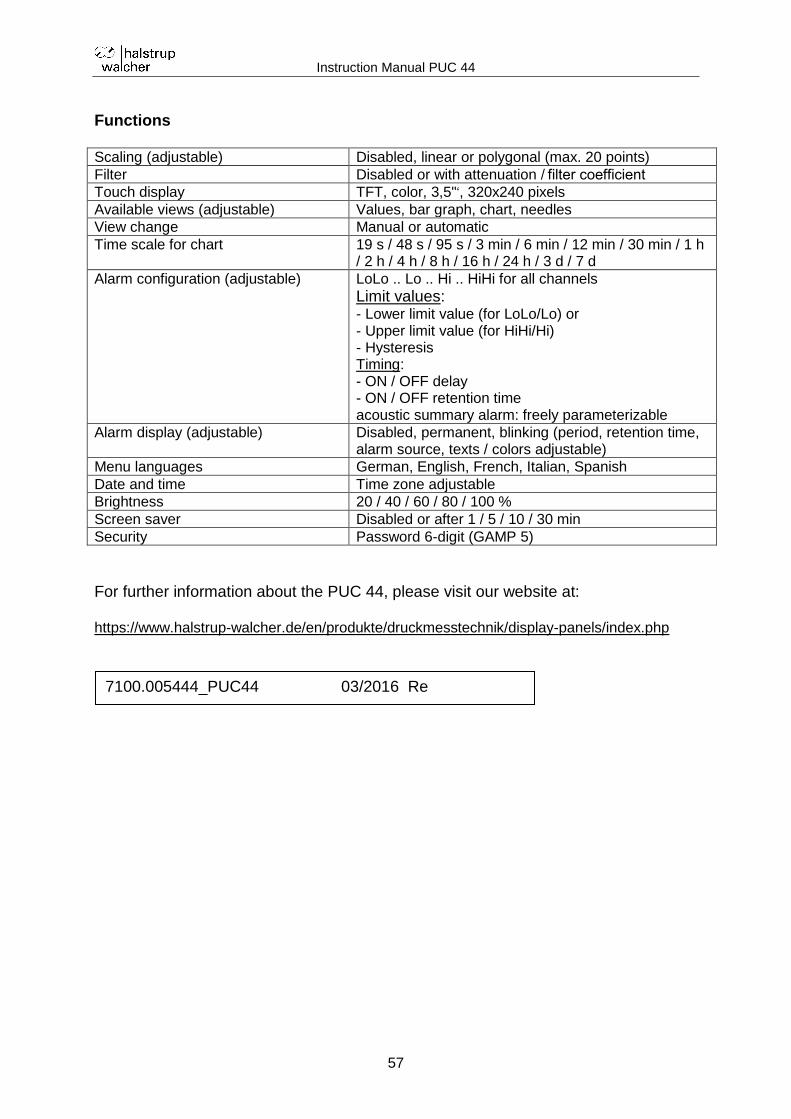
Functions Scaling (adjustable) Disabled, linear or polygonal (max. 20 points)
Filter Disabled or with attenuation / filter coefficient
Touch display TFT, color, 3,5"‘, 320x240 pixels
Available views (adjustable) Values, bar graph, chart, needles
View change Manual or automatic
Time scale for chart 19 s / 48 s / 95 s / 3 min / 6 min / 12 min / 30 min / 1 h / 2 h / 4 h / 8 h / 16 h / 24 h / 3 d / 7 d
Alarm configuration (adjustable) LoLo .. Lo .. Hi .. HiHi for all channels
Limit values: - Lower limit value (for LoLo/Lo) or - Upper limit value (for HiHi/Hi) - Hysteresis Timing: - ON / OFF delay - ON / OFF retention time acoustic summary alarm: freely parameterizable
Menu languages German, English, French, Italian, Spanish
Date and time Time zone adjustable
Brightness 20 / 40 / 60 / 80 / 100 %
Screen saver Disabled or after 1 / 5 / 10 / 30 min
Security Password 6-digit (GAMP 5)
For further information about the PUC 44, please visit our website at: https://www.halstrup-walcher.de/en/produkte/druckmesstechnik/display-panels/index.php