12
BY Instruction Manual 3 AND 4 BLADE CLASSIC GENERATION 2

BY
Instruction Manual
3 AND 4 BLADE CLASSIC GENERATION 2

INTRODUCTION:
Thank you for having chosen a MAX PROP® automatic feathering propeller for your vessel. This instruction booklet is designed to answer all your questions on installation and use of the Max-Prop. Please read it carefully and verify the correct working of the propeller before installing it on your boat.
1)
INSTALLATION:
The propeller is supplied already assembled for right or left rotation, according to the information received at order and with the pitch required if discussed at the time of the order, and is therefore ready to be fitted on the shaft. MAX PROP® parts are NOT interchangeable. Make sure, if you receive more than one propeller, that you do not interchange parts.
2)
x3
x1 x1x1
x2x1 x1For Sail Drives

Fit the MAX PROP® onto the propeller shaft, like a fixed propeller, and be sure that the key is proper dimension: A properly fit key has almost no clearance side to side but a very small clearance on its upper surface. This clearance is to avoid the propeller being pushed off center by a key which is too tall.
A)
Fill the prop with marine grease (supplied) using a grease fitting (supplied) inserted into the grease holes on the side of the propeller marked “GREASE”. The MAX PROP® CLASSIC GENERATION 2 propeller works properly only if the central body is completely filled with the correct grease. Verify that the grease is oozing from the rotating joints between the central part and the hub, so that all of the moving surfaces are perfectly oiled. The grease used must be a type of grease approved by MAX PROP® so it will remain fluid after years of use and will not get too stiff in cold water.
C)
Tighten the nut and secure it in place using the two allen head screws.B)
GREASE
3010
2812
1
GREASE
3010
2812
2
GREASE
3010
2812
3

GREASE
3010
2812
GREASE
3010
2812
GREASE
3010
2812
GREASE
3010
2812
4 5 6
7 9
GREASE
3010
2812
8
Fig.4
Move the blades into the feathered position, making sure that the rounded trailing edges of the blades are aft as shown in Fig. 4
D)
Before launching the boat, it is absolutely necessary to operate as follows:• Hold the propeller shaft.• Check that the blades of the propeller rotate freely from the forward to the reverse position
just by a light effort.• In the feathered position the blades must be perfectly lined up and set like Fig. 4.• Check that the propeller body is full of fluid marine grease.• Make sure that the propeller is protected from galvanic corrosion by using the usual zinc
anodes on the propeller and the shaft.
E)
GREASE
3010
2812

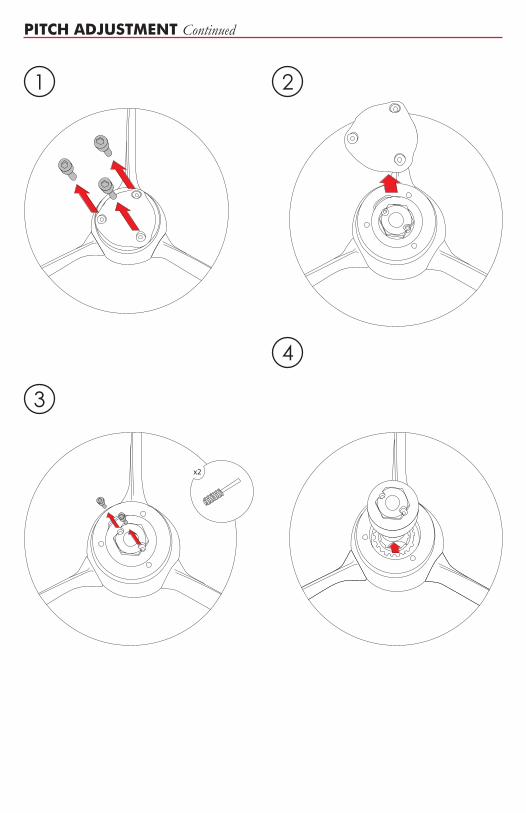
PITCH ADJUSTMENT:
The pitch on a MAX PROP® changes according to the diameter and the blades rotation angle. Fig. 1 shows the pitch in inches corresponding to the degree of blades angle for a given propeller diameter.
Diameter and pitch must be calculated as if MAX PROP® CLASSIC GENERATION 2 was a normal fixed propeller. MAX PROP® CLASSIC GENERATION 2 then offers the great advantage of pitch adjustability in order to optimize the performance of the propeller. If the engine does not reach the desired RPM, reduce the blade angle; on the contrary, if the engine exceeds the desired RPM, increase the blade angle. The MAX PROP® CLASSIC GENERATION 2 allows an angle variation of 1 degree increment, this corresponds to a variation in the engine RPM of about 7 % at the same boat speed. It’s possible to change either the pitch to optimize the engine performance, or the rotation (for ex. if you change the engine, or if there were a mistake when ordering the prop). If you have doubts about the rotation: shaft rotation is determined from the stern of the boat looking forward. With the engine in forward position clockwise rotation of the propeller means it is right hand “R”, and a counterclockwise rotation is a left hand “L”.Pitch and rotation of the MAX PROP® CLASSIC GENERATION 2 can be changed as follows:• Rotate the blades to the feathered position• Unscrew the zinc screws, and remove the zinc• Unscrew the locking nut screws and remove the nut • Using a circlip pliers, remove the circlip located inside the aft hub ring• Take the aft hub ring off (this is the part of the propeller body on which the zinc is attached)• Once the aft hub ring is off, pull the body of the propeller 2-3 cm, aft making a gap between the
body and the forward hub (The blades and body will stay together). Rotate the body to line up the reference mark on the forward hub to the correct rotation and blade angle desired. (Step 13 is an example of setting where the selected angle is 18° R rotation, OR 22° L rotation).
• Slide the body forward to engage fully onto the forward hub, keeping the reference mark lined up with the desired rotation and angle.
• Makesurethatthebladesareperfectlyfeathered.• Locate the reference mark on the aft hub ring (a dot). Then insert the aft hub ring in place, while
lining up the reference mark with the RIGHT or LEFT scale stamped on the propeller body (Step 15 the example shows the dot lined up in the RIGHT scale).
• Place the circlip back in its seat using the circlip pliers.• Tighten the nut and secure it with the locking-nut screws.• Re-install the zinc, and secure it with the 3 screws.
3)
Propeller Diameter12” 13” 14” 15” 16” 17” 18” 19” 20” 21” 22” 23” 24” 25” 26”
10º 4 4.3 4.6 4.9 5.2 5.5 6 6.3 6.7 7.1 7.4 7.7 8 8.3 8.612º 4.8 5.2 5.6 6 6.4 6.8 7.2 7.6 8 8.4 8.8 9.2 9.6 10 10.414º 5.6 6 6.6 7.1 7.6 8 8.4 8.8 9.4 9.8 10.4 10.8 11.2 11.6 12.216º 6.4 6.9 7.6 8.1 8.6 9.1 9.8 10.3 10.8 11.3 12 12.5 13 13.5 1418º 7.2 7.8 8.6 9.2 9.8 10.4 11 11.5 12.1 12.8 13.4 14 14.6 15.2 1620º 8.2 8.9 9.6 10.3 11 11.6 12.4 13 13.7 14.5 15 15.6 16.4 17 17.822º 9.2 10 10.7 11.4 12.2 12.9 13.6 14.3 15.1 16 16.8 17.5 18.2 18.9 19.824º 10 10.9 11.8 12.5 13.4 14.2 15 15.8 16.8 17.6 18.4 19.2 20.2 21 21.826º 11 12 12.8 13.8 14.7 15.7 16.6 17.4 18.4 19.3 20.2 21 22 22.9 23.828º 12 13 13.9 15 16 17 18 18.9 20 21 22 23 24 25 2630º 13 14 15.1 16.2 17.3 18.5 19.6 20.6 21.7 22.8 24 25 26.1 27.3 28.2
Inches of PitchFig.1
Bla
de A
ng
le
PITCH ADJUSTMENT Continued
1 2
3
x2
4

5
6
9
7
8

14 15
3030 1010LEFTRIGHT
13
2218
LEFTRIGHT
1822
20201624
11
2020
LEFTRIGHT
18221624
10
2020
LEFTRIGHT
18222218
2020
LEFTRIGHT
18222218
12

17
18 19
20
16

PROPELLER USE:
The MAX PROP®CLASSIC GENERATION 2 works automatically. By putting the transmission in gear the blades will engage in either forward or reverse (WARNING: do not change from forward to reverse and vice versa when the engine is running at high RPM ) and feathers from forward position when you turn off the engine and lock the shaft.
The best way to feather the propeller is:• Power at 2 to 3 knots in forward.• Kill the engine while still engaged in forward.
If your propeller has been greased properly it will feather in a fraction of a second as soon as you stop the shaft from freewheeling. DONOT kill the engine while in reverse. In this case the blades will be in the reverse position and cannot feather. You can actually use this feature to drive a shaft alternator.Modern transmissions are either mechanical or hydraulic. With a mechanical transmission, the best way to stop the shaft freewheeling is to engage the transmission in reverse ( WARNING: engage the reverse only after the engine has stopped completely). With a hydraulic transmission you must shut off the engine while still engaged in forward. The remaining hydraulic pressure will en effect lock the shaft for a few moments, enough for the MAX PROP® to feather.
WARNING:
It is important to follow the instruction below carefully so as to avoid a shock load to the gears on the blades and cone gear, that could be damaging to the teeth.• When going from forward to reverse and the opposite, it is necessary to idle down and
shift at low RPM’s between gear, that could be damaging to the teeth.
MAINTINANCE:
• The propeller must always be completely filled with recommended grease, the propeller should be greased at least once a year.
• Make sure that you always keep the zinc anodes in good condition. They must be replaced at least once a year, even if they still look ok. The propeller must be protected by a lot of zinc, so also use a zinc on the shaft when possible. When replacing it make sure that you clean the surfaces between the zinc and the propeller shaft in order to have a good electrical contact.
PROPELLER REMOVAL:
In order to remove the propeller you must first remove the zinc and remove the nut. Next fit a long armed gear puller over the front of the propeller as show in fig. 5. Tightening the center bolt of the gear puller will release the MAX PROP® from the propeller shaft.
If the bolt from the gear puller is not long enough to contact the end of the propeller shaft inside the MAX PROP® the MAX PROP® nut can be loosened and left in place. In this scenario the bolt from the puller will push against the back of the nut to release the propeller from the shaft.
4)
5)
6)
Fig.5

INSTRUCTIONS FOR THE PROPER WORKING OF THE BLOCKING NUT OF THE PROPELLER Fig. 7.
1. When it’s locked on the motor shaft, the nut must contact the 3 surfaces S1, S2, S3. Therefore, if a new nut has to be machined you must be sure that length L1 and L2 coincide precisely with the corresponding lengths of prop hub, and that length L3 is greater than the length of the threaded edge of motor shaft. To check that the work is done properly, you just have to spread a very thin coat of Prussian blue on the 3 surfaces S1, S2, S3. Insert then the nut in its seat in the hub and let the nut rotate softly in relation to the hub, with a light pressure. When this is done, the 3 surfaces of the hub must be painted in blue.
2. When fitting the prop on the motor shaft, it’s necessary to check that the threaded part of the motor shaft doesn’t touch the threaded end of the nut. Also, when the nut is tight, the blades rotation on their axis does not get hard. In case the blades rotation movement becomes hard, you have to remove from surface S1 a very small amount of material. This operation can be done simply by using a flat smooth file.
7)
Fig.7
Fig.8
SPECIAL NUT (FIG.8) ONLY FOR MAX PROP WITHANTI-SHOCK DEVICE
Unlike the standard nut, this kind of nut, when it’s locked on the motor shaft, must lean ONLY to surfaces S1 and S2 and is secured by 4 devices: 2 threaded pins, and a central screw with a dowel. When you mount the propeller on the motor shaft the same nut checking is necessary as previously described for fig. 7.
8)

MAX PROP PATENTED PROPELLERSPYI Inc., 12532 Beverly Park Rd., Lynnwood, WA 98087
Tel: 425-355-3669 Fax: 425-355-3661 [email protected] www.max-prop.com


