DIGIMED guaranties to the first owner of this product, of warranty against fabrication defects and for electrodes from the date of delivery, with sales receipt from or from the date of fabrication (or as identified) through the serial number.
DIGIMED declares this warranty null, if this equipment suffers any type of damage from any type of accident, abusive use, or use in disregard of the instruction manual, or if used with a electric current other than that specified for this product or is subject to excessive fluctuation on the electric current or if in case of evidence or tampering or repair by a non-authorized person.
This product was manufactured under the , according to .
This warranty does not cover any shipping and handling charges.
36 months6 months
"DIGIMED QUALITY AND ASSURANCE SYSTEM"ISO9001:2000
3
TURBIDITY PRINCIPLES
TURBIDITY MEASUREMENT
The measured Turbidity of determined sample, is the reading refered by light dispersity and absortion that goes thru the sample.
Turbidity does not mean suspended solids measurement, but a effect determination of light refracted through solids.
Turbidity measuremnts are used to evaluate the quantity of water sample. To understand turbidity it is helpful to think about the characteristics of mixtures.
A mixture is defined as Homogenous or Monophasic, when the components of the mixture are uniformly dispersed, or dissolved, throughout the mixture, Salt water is an example of a homogenous mixture or Solution. Heterogenous or Polyphasic mxitures are those whose components are not uniformely distributed throughout the mixturet. The components may simple be floating in the mixture, given enough time these components will settle out.This type of mixture is also called Suspension.
The clarity of a water sample is directly related to the amount of material suspended in the water. Turbidity measurements are a way to measure the amount of material suspended in a water sample. They are commonly used to monitor the effectiveness of filtration processes.
The DIGIMED Turbidity meter uses the principle of Nephelometry. As light of a known intensity is passed through a sample some of the light will be scattered by particles in the sample. A detector is placed at 90° to the sample to collect the scattered light. The intensity of the scattered light is compared to that of the source. This value is reported as a Nephelometric Turbidity Unit, or NTU. The meter is calibrated with Formazine standards of a known NTU.
Water can sometimes have color of its own (from humic sources, for example). This color may interfere with the light source, absorbing some of the light, and reducing the amount of light reaching the detector. This can cause the measurement to be skewed. The DIGIMED Turbidity Meter LED light source emits at a range close to infrared. In this range absorption is minimized, and turbidity measurements are more accurate.
4
As detection involves the difference between the light reaching the cuvette and transmitted by
the sample placed at the cuvette, it is convenient to minimize the effects that diminish the light
intensity transmitted, among those the most important, it is the absortion caused by the samples
color.
Because of this it is essential to work in a light wavelenght where absortion would be minimum
(close to infrared), if we work in a electromagnetic spectrum visible region, this color interferance
would certainly alter the results.
In order to quantify the turbidity, we can use many comparison standards, being NTU
(Nephelometric Turbidity Unit) scale the most common, patronized from formazine standard
suspensions. This way we would have a comparison standard scale between different materials,
in a way we can evaluate turbidity with precision.
Bibliographic References
Bela G. Lipták (chief editor) Analytical Instrumentation;
Howard A. Strobel and William R. Heineman, Chemical Instrumentation, A Systematic
Detector
Reflected Light @ 90°
TransmittedLightLight Emitting
near “ IR”
Cuvette
90°
TURBIDITY PRINCIPLES (cont.)
Specifications
APPLICATION Analyzer / Transmitter / Turbidity Controller ANALYZER Display Alphanumeric LCD 2 collumns x 16 characters Range 0 to 10 NTU Resolution 0.0001 NTU Relative Precision 0.01% (full scale) Analytic Method Nephelometric Wavelength 660 nm GENERAL Case Classification IP-67 Body Material Cast Alluminum SAE 323(Base)
Polyurethane (Front Lid) Electric Connection Terminal Barr Cable Input Cable Knockouts ½“ BSP (2x) and ¼”BSP (2x) Installation Flat Surface Relative Humidity 20 to 80 % Electrical Power 90 - 240 Vac (50/60 Hz) Power Consumption 3.5 VA Sample Flow 250 to 750 ml./min. Sample Pressure(mín./max.)
10 / 20 psi
Sample Temperature 5 to 40°C Weigth 5 Kg (11Lbs.) TRANSMITER Analogic Output 2x - 4 to 20 mA Digital Output RS-485 CONTROLLER Type ON-OFF / PWM 2x, NO (1A / 250 VAC) Set-Point from 0 to 100% of scale
Accessories Instruction Manual
CD Rom
5
Hardware for tubing and flat surface installation (2x)
U Clamp (SS 316) with nuts and screws (2x)
A Calibration Cup is also be supplied for Calibration purpose!
Mechanical Descriptions
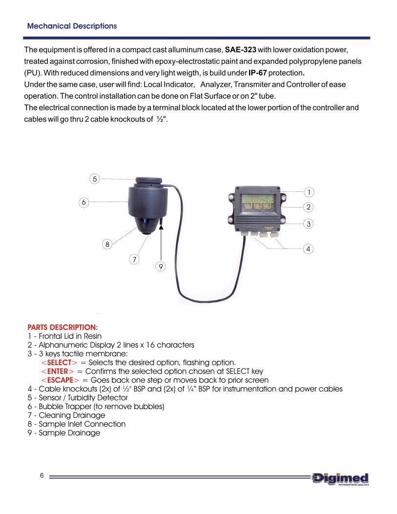
The equipment is offered in a compact cast alluminum case, SAE-323 with lower oxidation power,
treated against corrosion, finished with epoxy-electrostatic paint and expanded polypropylene panels
(PU). With reduced dimensions and very light weigth, is build under IP-67 protection.
Under the same case, user will find: Local Indicator, Analyzer, Transmiter and Controller of ease
operation. The control installation can be done on Flat Surface or on 2" tube.
The electrical connection is made by a terminal block located at the lower portion of the controller and
cables will go thru 2 cable knockouts of ½".
PARTS DESCRIPTION:
<SELECT><ENTER><ESCAPE>
1 - Frontal Lid in Resin2 - Alphanumeric Display 2 lines x 16 characters3 - 3 keys tactile membrane: = Selects the desired option, flashing option. = Confirms the selected option chosen at SELECT key = Goes back one step or moves back to prior screen4 - Cable knockouts (2x) of ½" BSP and (2x) of ¼“ BSP for instrumentation and power cables5 - Sensor / Turbidity Detector6 - Bubble Trapper (to remove bubbles)7 - Cleaning Drainage8 - Sample Inlet Connection 9 - Sample Drainage
6
6
7
5
1
2
3
4
9
8
ANALYZER TB-44BB
Below you will find panel dimensional for installation in flat surface and distances between support holes.
Dimensional
Hose ½” Drainage
7
Bubble Trapper (remove bubbles) in Black PPPU Hose - Diam. 6x1mm (Sample Inlet)Turbidity Sensor / DetectorCable Knockout 1/4^ (2x)Cable Knockout 1/2^ (2x)PU Tactile MembraneAlphanumeric Display 2lines x 16characters
Frontal Lid in ResinITEM DESCRIPTION
ELECTRICALPOWER
SELECT FUNCTION
Obs: Dimensions in Millimeters
Cable Length: 1000 -+10
SELECTSELECT ENTERENTER ESCAPEESCAPE
Equipment Installation
Follow rigorously below instructions:
1- Take off the equipment from it’s box and verify for any possible damages, caused by it’s transportation.2- Install the controller in a strategic place, of ease access and operation, free of vibrations and vapors.3- Avoid direct exposure of the controller to solar rays and in case if necessary, protect the controller.4- Proceed with terminal connections of cables at terminal block.5- Inspect the electrical installation in order to certify that all connections are correct.6- Verify the power that is being supplied and make sure to connect it the proper place.7- Connect the circuit breakers from the power distribution box.
3.1. Important Recommendations
3.1.1. The equipment must be Beingso, the power cable of Control Valves, Solenoids, Alarms, etc, must be connected directly at theDistribution Box, and " " at the equipment connection board.3.1.2. if the equipment and probe are firmly to it’s respectiveinterconnection cables. If any small gap is found, protect the cable with " "
(IP-67).3.1.3. . It reduces impedance, generating measuring errors. Verify thecable knockout and if necessary, using a hair.3.1.4. s length,Contact Digimed Customer Service.
Electrical Power independent
neverVerify cable knockouts
high fusion tape
Be careful with Humidity!!dry the connection block
Do not cut or try to attach the connection cable.
from other system components.
untilreached a perfect attachment to the cable press, never use silicon. This proceeding has function toretain IP ratings
In case you need to change it’
3.1.5. ON-OFF are , offering innumerous advantages for the equipment, such as:no presence of sparks, faster commutation, noise practically inexistent, no presence of RF interference,etc. The outputs can commute any charge, since they are ,
.
outputs thyristor
powered by alternate tension (VAC) Limited to 250V / 1A
type
8
Sensor Cable
RF Shield
Meas.
Yellow
Green
Electr. Shield
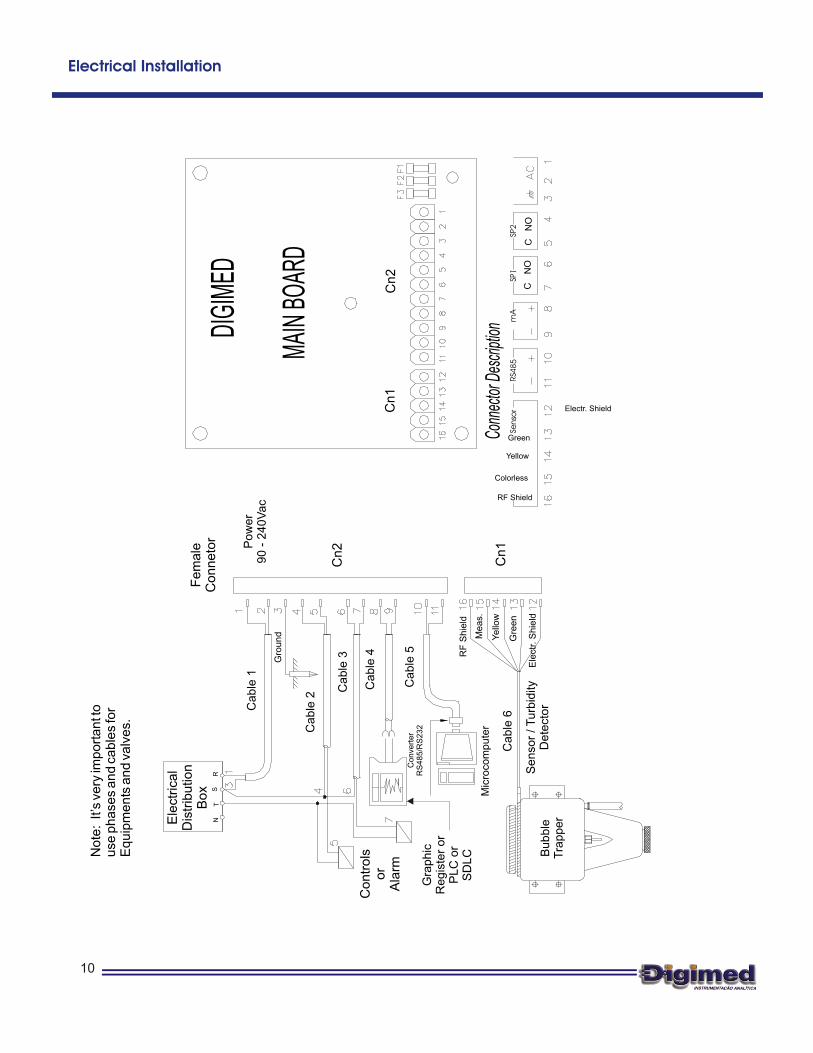
CN2 - Connector 2
CN1 - Connector 1
FUSES
Slots Connection1 and 2 Electrical Power for 90/240 Vac 50/60Hz connection3 Ground4 and 5 SP2 - Set-Point 2 for alarm or control 6 and 7 SP1 - Set-Point 1 for alarm or control 8 and 9 Digital Transmission Output 4 to 20 mA
12 Turbidity Sensor Cable Shield
F1 General Fuse (3.0A)F2 Set-Point 2 Fuse (1.0 A)F3 Set-Point 1 Fuse (1.0A)
Remove the Sensor/Turbidity Detector (5). Using a soft sponge and neutral soap, wash the Led and
the photocell Lenses. After this, dry it using a soft absorbent paper, a type that will not leave
residues.
BUBBLE TRAPPER CLEANING
Clean the Bubble Trapper. Remove the locking ring, then un-thread the Drainage Lid, so the sample
can be drained from the instrument. Wash it using neutral soap and dry it using a soft absorbent
paper, a type that will not leave residues. Make sure to look for areas where residues can
accumulate
(shown below picture). Remove the Bubble trapper as shown below and after cleaning make sure to
Areas where residues can accumulate
Photocell
LED
11
Bubble Trapper
Body
Drainage Lid
Bubble Trapper
Body
Remove the Bubble Trapper by pulling it up.
Equipment Cleaning
Totally remove the Bubble Trapper from the body. Wash it using neutral soap and a small brush,
using circular movements, clean the openings. Rinse using plenty of water and dry it using a soft
absorbent paper, a type that will not leave residues. After the cleaning is done, re-install the Bubble
Trapper back at the body and proceed to calibration.
12
Openings
Bubble Trapper
Equipment Calibration
1) Prepare the calibration standards need for your application (see page 14 for instructions on how to
formulate standards).
2) Close the process Sample Inlet.
3) Un-thread the Drainage Lid, in order to remove the sample located inside the Bubble Trapper.
4) Remove the Sensor Unit from the Bubble Trapper and insert the calibration cup, as shown below.
Note: the calibration Cup MUST be clean! Residues FREE!
13
Sensor Unit
Calibration Cup
Removing the Sensor Unit
Placing the Calibration Cup
5) Add the Turbidity Standard to the Calibration Cup, until it overflows some inches.
6) Replace the Sensor Unit back to the Bubble Trapper and wait about 15 seconds for stabilization.
7) Access the instrument calibration menu and execute the calibration steps (see page 20).
8) After the calibration is done, thread the Drainage Lid back in place. Remove the Sensor Unit and
take out the Calibration Cup.
8) Replace the Sensor Unit back at Bubble Trapper and open the Process Sample Inlet.
10) Execute Reading!
14
TURBIDITY STANDARD PREPARATION
INSTRUCTIONS FOR CALIBRATION SOLUTION PREPARATION
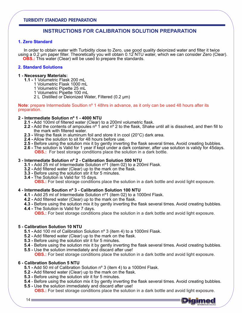
1. Zero Standard
2. Standard Solutions
In order to obtain water with Turbidity close to Zero, use good quality deionized water and filter it twice using a 0.2 µm paper filter. Theoretically you will obtain 0.12 NTU water, which we can consider Zero (Clear).
This water (Clear) will be used to prepare the standards.
1 - Necessary Materials: 1.1 - 1 Volumetric Flask 200 mL 1 Volumetric Flask 1000 mL 1 Volumetric Pipette 25 mL 1 Volumetric Pipette 100 mL 2 L Distilled or Deionized Water, Filtered (0.2 µm)
2 - Intermediate Solution nº 1 - 4000 NTU 2.1 - Add 100ml of filtered water (Clear) to a 200ml volumetric flask. 2.2 - Add the contents of ampoules nº 1 and nº 2 to the flask, Shake until all is dissolved, and then fill to the mark with filtered water. 2.3 - Wrap the flask in aluminum foil and store it in cool (20°C) dark area. 2.4 - Allow the solution to sit for 48 hours before use. 2.5 - Before using the solution mix it by gently inverting the flask several times. Avoid creating bubbles. 2.6 - The solution is Valid for 1 year if kept under a dark container, after use solution is validy for 45days.
3 - Intermediate Solution nº 2 - Calibration Solution 500 NTU 3.1 - Add 25 ml of Intermediate Solution nº1 (item 02) to a 200ml Flask. 3.2 - Add filtered water (Clear) up to the mark on the flask. 3.3 - Before using the solution stir it for 5 minutes. 3.4 - The Solution is Valid for 15 days.
4 - Intermediate Soution nº 3 - Calibration Solution 100 NTU 4.1 - Add 25 ml of Intermediate Solution nº1 (item 02) to a 1000ml Flask. 4.2 - Add filtered water (Clear) up to the mark on the flask. 4.3 - Before using the solution mix it by gently inverting the flask several times. Avoid creating bubbles. 4.4 - The Solution is Valid for 7 days.
5 - Calibration Solution 10 NTU 5.1 - Add 100 ml of Calibration Solution nº 3 (item 4) to a 1000ml Flask. 5.2 - Add filtered water (Clear) up to the mark on the flask. 5.3 - Before using the solution stir it for 5 minutes. 5.4 - Before using the solution mix it by gently inverting the flask several times. Avoid creating bubbles. 5.5 - Use the solution immediately and discard after use!
6 - Calibration Solution 5 NTU 5.1 - Add 50 ml of Calibration Solution nº 3 (item 4) to a 1000ml Flask. 5.2 - Add filtered water (Clear) up to the mark on the flask. 5.3 - Before using the solution stir it for 5 minutes. 5.4 - Before using the solution mix it by gently inverting the flask several times. Avoid creating bubbles. 5.5 - Use the solution immediately and discard after use!
OBS.:
Note nº 1 48hrs in advance, as it only can be used 48 hours after its preparation.
OBS.:
OBS.:
OBS.:
OBS.:
OBS.:
: prepare Intermediate Soultion
For best storage conditions place the solution in a dark bottle.
For best storage conditions place the solution in a dark bottle and avoid light exposure.
For best storage conditions place the solution in a dark bottle and avoid light exposure.
For best storage conditions place the solution in a dark bottle and avoid light exposure.
For best storage conditions place the solution in a dark bottle and avoid light exposure.
Equipment Operation
Acess Keys
Menus are self explanatory for ease interaction. In order to introduce or change data,menu offers options always flahsing, that can be changed by pressing <SELECT> key.To confirm the flashing option, press <ENTER> key.<ESCAPE>key is used to change data
or correct any wrong information chosen during set up (it goes back to prior screen at every touch).
When turned on, the Model and software Version will be displayed.
Performs Memory Check
Main Menu Screen. In order to access the Set Up Menu, press
DIGIMED Mod. TB-44BB V1.0
DISPLAY TEST
S1: S2: 0.361 NTU
SELECT FUNCTIONREAD SET UP
SELECT
ENTER
ESCAPE
15
AUTO CHECK 100%
• • • • • • • •• • • • • • • •
PASSWORD: _ _ _
Go to Page 16
Go to Page 15
Performs a Display check
Allows user to check the Set Points (S1 and S2) STATUS. Press and hold <ESCAPE> key for about 5seconds, in order to exit reading mode.
Equipment Operation - Set Up
Duirng Set Up, user will have access to calibration points, Control Output and Transmiting Outputs.
CONFIG. INSTRUM.? / YES NO
RANGE0 - 10 NTU
DEFAULT CALIBRAT.? / YES NO
READ CALIBRATION: / MANUAL AUTO
Press key until desired option flashes, then press to confirm Selected option.
<SELECT><ENTER>
User is given the option to Configure the instrument. Press ,until desired option fashes, then press to confirm
<SELECT><ENTER>
CALIBRATION POINTS: 1 / 2 / 3
CALIBRATIONPt.1: 0.120 NTU < >
READING MODE:CONTIN. / AVERAGE
< decrease 1 unit
> increase 1 unit(***)See below
Please refer to instructions below every time you see the symbols ***In order to adjust the value, press SELECT key in order to stop scrolling and pay attention to the blinking arrow (either < to Decrease, or > to Increase). Press SELECT key to change the blinking arrow. Once you decided to increase or decrease, press ENTER key to confirm your option, then press SELECT key in order to increase or decrease the value. If you pass the number by mistake, press ENTER key to move to next step, then press ESCAPE key and you will moved back one step, then repeat above operation until you reach the desired value.
< >
16
LANGUAGE: PORT./ / SPANISHENGLISH
The Range is pre-set at the factory and cannot beModified!
CONFIRM? / YES NO
User is given the option to re-store factory default. Press ,until desired option fashes, then press to confirm. This option will return to factory defaults, including the calibration.
<SELECT><ENTER>
User is given the option to choose the number of calibration points in order to build the calibration curve. Press ,until desired option fashes, then press to confirm.
<SELECT><ENTER>
CALIBRATIONPt.: 0.3000 NTU < >
CALIBRATIONPt.: 1.0000 NTU < >
User is given the option to choose the Reading Mode as Continuous or Average. Press ,until desired option fashes, then press
to confirm. <SELECT>
<ENTER>
Go to page 16
Go to page 16
READING TIME: 5s. < >
User will be given the option to adjust the Read value, after Read operation isperformed. This will allow the user, if necessary, to match the read results,between Lab and Process. In order to Choose YES or NO, press
key for the flashing option, then press key to Confirm.<SELECT> <ENTER>
CONFIG. DISPLAY ? / YES NO
MAX.: 100 NTU < >
CONTACTS CONFIG.? / YES NO
SET POINT S1: 1.0000 NTU < >
User will be given the option to configure info to be displayed at the screen. In order to choose YES or NO, press
key for the flashing option, then press key to confirm.<SELECT> <ENTER>
User is given the option to choose between Direct ofReverse Acting for S1. Press key for theFlashing option, then press key to confirm.
<SELECT><ENTER>
BURN-OUT CONFIG.: STAND BY: HOLD
User is given the option to configure the burn out for S2 when theinstrument goes to Stand By mode. Press untildesired option flashes, then press key.
<SELECT><ENTER>
Equipment Operation - Set Up (cont.)
In order to choose YES or NO, press key for the flashing option, then press key to confirm.
<SELECT><ENTER>
17
BARGRAPH ? / YES NO
User will be given the option to adjust the Set Point 1 as On orOff. In order to choose the desired opiton, press key for the flashing option, then press key toConfirm.
<SELECT><ENTER>
MIN.: 0 NTU < > User will be given the option to define the Min and Max valuesfor the Bargraph. Refer to *** (on page 15) in order to adjustthe values.
CONFIGURATION OF S1: / ON OFF
User will be given the option to accept a Bargraph during Read Mode, showing the lenght of the process. In order to choose YES or NO, press key for the flashing option, then press key to confirm.
<SELECT><ENTER>
User will be given the option to adjust the value for the Set Point S1. Refer to *** (on page 15) in order to adjust theValue.
ACTING: / DIRECT REVERSE
HYSTERESES: 0.0000 NTU < >
User will be given the option to adjust the value for the Hystereses for S1. Refer to *** (on page 15) in order to adjustThe Values.
CONFIGURATION OF S2: / ON OFF
User will be given the option to adjust the Set Point 2 as On orOff. In order to choose the desired opiton, press key for the flashing option, then press key toConfirm.
<SELECT><ENTER>
SET POINT S2: 2.0000 NTU < >
User will be given the option to adjust the value for the Set Point S2. Refer to *** (on page 15) in order to adjust theValue.
ACTING: / DIRECT REVERSE
User is given the option to choose between Direct ofReverse Acting for S2. Press key for theFlashing option, then press key to confirm.
<SELECT><ENTER>
HYSTERESES: 0.000 NTU < >
User will be given the option to adjust the value for the Hystereses for S2. Refer to *** (on page 15) in order to adjustThe Values.
BURN-OUT CONFIG. STAND BY: HOLD
BURN-OUT CONFIG. STAND BY: HOLD
User is given the option to configure the burn out for S1 when theinstrument goes to Stand By mode. Press untildesired option flashes(4mA, 20mA or Hold), then press
key.
<SELECT>
<ENTER>
Go to page 17
Go to page 17
User is given the option to configure the burn out for S2 when theinstrument goes to Stand By mode. Press untildesired option flashes, then press key.
<SELECT><ENTER>
User is given the option to configure the burn out for S2 when theinstrument goes to Stand By mode. Press untildesired option flashes(4mA, 20mA or Hold), then press
key.
<SELECT>
<ENTER>
PLACE AMP METER@ OUTPUT 4 - 20 mA
At this screen, user canAdjust the value for 20 mA.
ADJUST OF 4 mA<SEL> - <ESC>+
In case the value is higher than 4mA, press keyuntil the amp meter indicates 4 mA. In case the value is lowerthan 4mA, press key until the amp meterindicates 4mA. Finalyze by pressing key.
<SELECT>
<ESCAPE><ENTER>
ADJUST OF 20 mA<SEL> - <ESC>+
CONFIG. RS485 ? / YES NO
At this screen, user canCalibrate the Output of 4mA and 20mA
At this screen, user canAdjust the value for 4 mA.
18
CONFIG. CURRENT ? / YES NO
User will be given the option to configure the Current Output.In order to choose YES or NO, press key for theFlashing option, then press key to confirm.
<SELECT><ENTER>
Equipment Operation - Set Up (cont.)
OUTPUT CONFIG.:mA. User will be given the option to configure the Current Output.
OUTPUT mA:/ ON OFF
User will be given the option to turn Current Output On or Off.In order to choose On or Off, press key for theFlashing option, then press key to confirm.
<SELECT><ENTER>
VALUE FOR 4mA: 0.0000 NTU < >
User will be given the option to adjust the value for 4mA Output. Refer to *** (on page 15) in order to adjust theValue.
VALUE FOR 20mA: 100.00 NTU < >
User will be given the option to adjust the value for 20mA Output. Refer to *** (on page 15) in order to adjust theValue.
BURN-OUT CONFIG.: STAND BY: HOLD
User is given the option to configure the burn out for S2 when theinstrument goes to Stand By mode. Press untildesired option flashes, then press key.
<SELECT><ENTER>
BURN-OUT CONFIG. STAND BY: HOLD
User is given the option to configure the burn out for Currentwhen theinstrument goes to Stand By mode. Press untildesired option flashes(4mA, 20mA or Hold), then press
key. For Hold, the output access the transmission andwait for the instrument returns to reading mode.
<SELECT>
<ENTER>
CALIBRATE mA? / YES NO
User will be given the option to calibrate the Current Output.In order to choose YES or NO, press key for theFlashing option, then press key to confirm.
<SELECT><ENTER>
CONFIRM? / YES NO
Connect the amp meter to the 4-20mA output in order to perform the calibration.
READY? Press key when ready!<ENTER>
In case the value is higher than 20mA, press keyuntil the amp meter indicates 20 mA. In case the value islower than 20mA, press key until the amp meterindicates 20mA. Finalyze by pressing key.
<SELECT>
<ESCAPE><ENTER>
User will be given the option to use RS485. In order to choose YES or NO, press key for the flashing option,Then press key to confirm.
<SELECT><ENTER>
Go to page 18
A
19
PROTOCOL: / PROPRIET MODBUS
User will be given the option to choose between Priproetary orModBus. In order to choose between them, press keyuntil desired option flashes, then press key to confirm.
<SELECT><ENTER>
Equipment Operation - Set Up (cont.)
SPEED (100bps):12 24 48 96
BITS:/ 7 8
User will be given the option to choose the Bits desired.In order to choose, press key until desired option flashes, then press key to confirm.
<SELECT><ENTER>
COMMUNICATION - IDNUMBER: 1 < >
User will be given the option to choose the Transmition Speed desired. In order to choose, press key untilDesired option flashes, then press key to confirm.
<SELECT><ENTER>
User will be given the option to define the instrumentidentification number within the network. Refer to page15 (***), to follow instructions on how to modify this number.
WAIT..................................
A
Equipment Operation - Calibrate
In order to calibrate the Analyzer, user will need to prepare primary formazine standards. Do not forget toclean the Calibration Reservoir with deionized water every time the Standard is changed.
TURBIDIMETER
READ SET UP
0.210 NTU
Press and hold key for about 6 seconds.
<ESCAPE>
Read option will flash, then presskey to confirm the option.<ENTER>
Press key, until Calibrate option flashes, then press key to confirm.
<SELECT> <ENTER>
TURBIDIMETERREAD CALIBRATE
READY ?
PLACE SENSOR@ 1.0000 NTU
Remove the Sensor/Turbidity Detector (5) and place it at the Calibration Cup with the referedsolution and when ready, press key.Wait for 5 minutes then press key.
<ENTER><ENTER>
WAIT STABILIZATION
GO TO SAMPLE !READY ?
READY ?
WAITSTABILIZATION
20
CAL.:1.0000 NTU / YES NO
Press key, until the desired optionflashes, then press key to confirm.User will have to accept or not this calibataionpoint. The Calibration values are chosenduring set up operation and so are the numberOf calibration points.
<SELECT> <ENTER>
CONFIRM: / YES NO
Press key, until desired option flashes, then press key to confirm.
<SELECT> <ENTER>
PLACE SENSOR@ 0.3000 NTU
CAL.:0.3000 NTU / YES NO
CONFIRM: / YES NO
If Standard is within specifications!
0.210 NTU
Instrument is ready to performreading! Return Sensor TurbidityDetector (5) back to the instrument and press key. <ENTER>
Note: if for any reason, any problem occurs, user will be prompted with a message “Standard out of specs.”, Press key, message will follow “Confirm Standard? Yes or No”. Select the option desired. Verify if Standard used matches the value displayed and chosen during Set Up Operation!
<ENTER>
Equipment Operation - Read
During these steps the user will have the opportunity to read the Turbidity. Before you start with reading,verify if the bubble eliminator is clean, if the drainage is connected and “open” and if the sample is flowingCorrectly. Finally connect the sensor to the bubble eliminator.
TURBIDIMETER
READ SET UP
At flashing opiton , press key to
Confirm the option.
Read <ENTER>
TURBIDIMETER
READ CALIBRATE
When Ready, press key.<ENTER>
STAND BY
0.413 NTUIn order to go to STAND BY
press key.<ENTER>
CALIBRATE READING0.413 NTU < >
GO TO SAMPLE! READY?
0.413 NTU
To return to Reading Mode press key.<ENTER>
In order to check the status of SET POINTS andthe output current value, press key.It will aslo be possible to execute the Manual Calibration (read value adjustment), if option was chosen during Set Up Operation.
<SELECT>
At this point the user can adjust the Reading valueto a known sample value. Refer to page 15 onhow to proceed with value adjustment.
At flashing opiton , press key to
Confirm the option.
Read <ENTER>
21
4,67 mA
S1 : S2 :
0.413 NTUIn case the user desires to go back to Main Menu,press key for about 6 Seconds.<ESCAPE>


![SCM Manual[1] - Welcome to Sechang Instruments!download.sechang.com/pds/2000/2000_21920a.pdf · · 2015-01-08English Index . 25 28 15 23 23 24 10 13 13 ... (Count Per Minut Radico](https://static.documents.pub/doc/80x56/5b1914e77f8b9a1e258c7a04/scm-manual1-welcome-to-sechang-instruments-2015-01-08english-index.jpg)


