by amperes electronics www.ampereselectronics.com VER 1/05 INSTR UCTION MANU AL AC 3601 MANUAL STANDBY AMPLIFIER CHANGEOVER UNIT Thank you for choosing another quality product from Amperes Electronics. AC3601 succeeded its predecessor with an additional feature, ie, cascading of amplifier changeover units can be done much easier, thus enable a standby amplifier to serve more duty power packs without limitation to the unit counts. This manual standby amplifier changeover serves 6 duty amplifiers with one standby. Reliability and durability is main concern and thereby we incorporate protection circuitries such as priority changeover and standby amplifier overloading prevention. Installing AC3601 is a definitely the wise choice, getting a value more than the price itself. DUTY AMPLIFIER PRIORITY STANDBY TAKEOVER NORMAL 1 2 3 4 5 6 amperes
Transcript
by amperes electronicswww.ampereselectronics.com
VER
1/0
5
INSTRUCTION MANUAL
AC 3601MANUAL STANDBY AMPLIFIER CHANGEOVER UNIT
Thank you for choosing another quality product from Amperes Electronics.
AC3601 succeeded its predecessor with an additional feature, ie, cascading of amplifier changeover units can be done much easier, thus enable a standby amplifier to serve more duty power packs without limitation to the unit counts.
This manual standby amplifier changeover serves 6 duty amplifiers with one standby. Reliability and durability is main concern and thereby we incorporate protection circuitries such as priority changeover and standby amplifier overloading prevention.
Installing AC3601 is a definitely the wise choice, getting a value more than the price itself.
DUTY AMPLIFIERPRIORITY
STANDBY TAKEOVERNORMAL
1 2 3 4 5 6
amperes
amperes
DUTY AMPLIFIERPRIORITY
STANDBY TAKEOVERNORMAL
1 2 3 4 5 6
INAMP.6DC INPUT
+
OUT24V USAGEOFNON RECOMMENDED INOUT
(PS301SRECOMMENDED)
DAMAGE TOTHIS EQUIPMENTPOWERSUPPLY UNITMAYCAUSE
DC SUPPLY RATING:24VDC,0.5A
-
COM
100V
COM
100V
100V
AMP.1OUTOUT ININOUTOUT ININ
100V
COM
100V
COM
100V
COM
COM
100V
COM
COM
100V
COM
100V
COM
100V
COM
100V
100V
DUTY AMPLIFIERINPUTSAMP.4AMP.3AMP.2 AMP.5
amperes electronicsanother quality product from
WIRING CONNECTIONS
AMP.IN
AMP.OUTS/BY IN
INPUTS OUTLINK
OUTINCOM
100V
COM
DUTYAMP
S/BY AMP
CASCADES/BY AMP INLINK LINK OUT - TONEXTAC601C
MAXLOAD/CH- 400W / 100VLINEPLEASE OBSERVEPOLARITY
AC601C
TO ZONESELECTORORSPEAKERS
LINK IN - FR.N-1 AC601CSERIAL NBR
STANDBY AMPLIFIER
DUTY AMPLIFIER # 06
DUTY AMPLIFIER # 01
AMPERES AC3601
LOW PRIORITY
HIGH PRIORITY
1 6 STANDBY AMPLIFIER INPUTDUTY AMPLIFIER INPUT
AMP OUT 1
AMP OUT 6
1
6
PAGE 2
DISCLAIMER
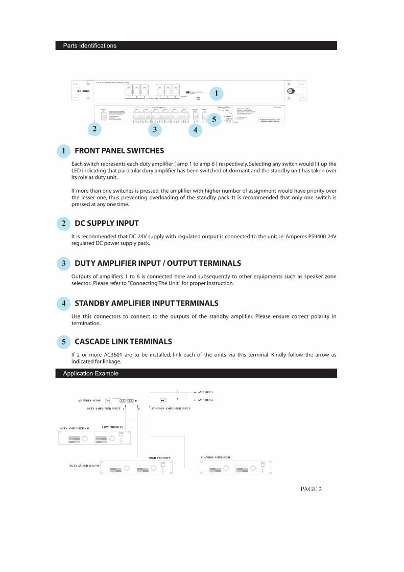
1 FRONT PANEL SWITCHES
Each switch represents each duty amplifier ( amp 1 to amp 6 ) respectively. Selecting any switch would lit up the LED indicating that particular dury amplifier has been switched ot dormant and the standby unit has taken overits role as duty unit.
If more than one switches is pressed, the amplifier with higher number of assignment would have priority overthe lesser one, thus preventing overloading of the standby pack. It is recommended that only one switch is pressed at any one time.
2 DC SUPPLY INPUT
It is recommended that DC 24V supply with regulated output is connected to the unit. ie. Amperes PS9400 24V regulated DC power supply pack.
3 DUTY AMPLIFIER INPUT / OUTPUT TERMINALS
Outputs of amplifiers 1 to 6 is connected here and subsequently to other equipments such as speaker zoneselector. Please refer to "Connecting The Unit" for proper instruction.
4 STANDBY AMPLIFIER INPUT TERMINALS
Use this connectors to connect to the outputs of the standby amplifier. Please ensure correct polarity in termination.
5 CASCADE LINK TERMINALS
If 2 or more AC3601 are to be installed, link each of the units via this terminal. Kindly follow the arrow as indicated for linkage.
1
2 3 45
amperes
DUTY AMPLIFIERPRIORITY
STANDBY TAKEOVERNORMAL
1 2 3 4 5 6
Parts Identifications
Application Example
INAMP.6DCINPUT
+
OUT24V USAGEOFNON RECOMMENDED INOUT
(PS301SRECOMMENDED)
DAMAGETOTHISEQUIPMENTPOWERSUPPLYUNITMAYCAUSE
DCSUPPLYRATING:24VDC,0.5A
-
COM
100V
COM
100V
100V
AMP.1OUTOUT ININOUTOUT ININ
100V
COM
100V
COM
100V
COM
COM
100V
COM
COM
100V
COM
100V
COM
100V
COM
100V
100V
DUTYAMPLIFIERINPUTSAMP.4AMP.3AMP.2 AMP.5
INPUTS LINK
OUTINCOM
100V
COM
CASCADES/BYAMP
24V DCAMPERES PS9400
TO SPEAKER ZONE SELECTOR TO POWER AMPLIFIER
STANDBY AMPLIFIER
NOTE :DO NOT JOIN COMMON LINES OF DIFFERENT AMPLIFIERSOBSERVE POLARITY WHEN CONNECTINGCABLE SIZE UP TO 2.5 MM SQ
REPEAT FORAMP #2 TO #6
100V
COM IN O
UT
S/BYAMPINPUTS
CASCADELINK
SINGLE UNIT INSTALLATION
INPUTSS/BYAMP
COM
100V
LINKCASCADE
OUTIN
MULTIPLE UNIT INSTALLATION
100V
COM IN O
UT
S/BYAMPINPUTS
CASCADELINK
UNIT 1
UNIT 2
UNIT 3
STANDBY AMPLIFIER
NOTE :THE EXAMPLE SHOWS :
~ 1 STANDBY AMPLIFIER TO SERVE 18 OR LESSDUTY AMPLIFIERS
~ 3 UTS OF AC3601 ARE USED~ UNIT 3 SHALL HAVE PRIORITY OVER OTHERS
Operating voltage 24V DC : 0.2APower consumption Standby : 82mW, 3.4 mA
Operating : 1.3W, 50 mA
Zone load rating 400 W / 100 V line input ( max )No of amplifier inputs 6 duty, 1 standbyChangeover indication Front panel LED for duty amplifier being
changed overSwitching mode Via front panel switches
Cable connections Plug in detachable connectors with screwCable size Up to 2.5 mm sq
Dimensions 482 (W) x 44 (H) x 150 (D) mmWeight 2.1 kgColour Black, powder epoxy coated
PAGE 3
PRIORITY 2
PRIORITY 1
Cabling Diagram
Technical Specification
Only Amperes Electronics Service Centres are allowed to make warranty repairs : a list of AmperesElectronics Service Centres may be asked for by the purchaser or send directly to AmperesElectronics Sdn Bhd or its authorized master distributor. This warranty is not valid if repairs areperformed by unauthorized personnel or service centres.
This warranty covers only repairs and replacement of defective parts ; cost and risks of transportation as well as removal and installation of the product from the main system are for the account of the purchaser.This warranty shall not extend to the replacement of the unit.
This warranty does not cover damages caused by misuse, neglect, accident of the product as well as using the product with power supply voltage other than shown on the product, or any other powersupply source / adaptor not recommended by the manufacturer.
This warranty does not cover damages caused by fire, earthquakes, floods. lightning and every causenot directly related to the unit.
This warranty does not include any indemnity in favor of the purchaser or the dealer for the periodout of use of the unit; moreover the warranty does not cover any damages which may be caused topeople and things when using the product.
This warranty certificate is valid only for the described product, and is not valid if modifications aremade on this certificate or on the identification label applied on the product.
This warranty covers all the material and manufacturing defects and is valid for a period of 12 months from the date of purchase or for a longer period in countries where this is stated by a national law. In this case, the extension is valid only in the country where the product is purchased.
Amperes Electronics Sdn Bhd is not obliged to modify previously manufactured products under warranty if the design changes or improvements are made.
WARRANTY CONDITIONS
PAGE 4
DISCLAIMER
Information contained in this manual is subject to change without prior notice and does not represent a commitment on the part of the vendor. AMPERES ELECTRONICS SDN BHD shall not be liable for any loss or damages whatsoever arising from the use of information or any error contained in this manual.
It is recommended that all services and repairs on this product be carried out by AMPERES ELECTRONICS SDN BHD or its authorized service agents.
AMPERES series must only be used for the purpose they were intended by the manufacturer and in conjunction with this operating manual.
AMPERES ELECTRONICS SDN BHD cannot accept any liability whatsoever for any loss or damages caused by service, maintenance or repair by unauthorized personnel, or by use other than that intended by the manufacturer.
A Product By Amperes Electronicswww.ampereselectronics.com
ISO 9001: 2008Design & Manufacture of Public Address Equipment and Systems


![AMP T-Kernel Specification - TRON Forum...AMP T-Kernel Specification / Ver. 1.00.00 7 TEF021-S001-01.00.00/en [Figure 21(a)] When an asynchronous initialization handler completes processing](https://static.documents.pub/doc/80x56/60bd5802d0b9540b904f58da/amp-t-kernel-specification-tron-amp-t-kernel-specification-ver-10000.jpg)


