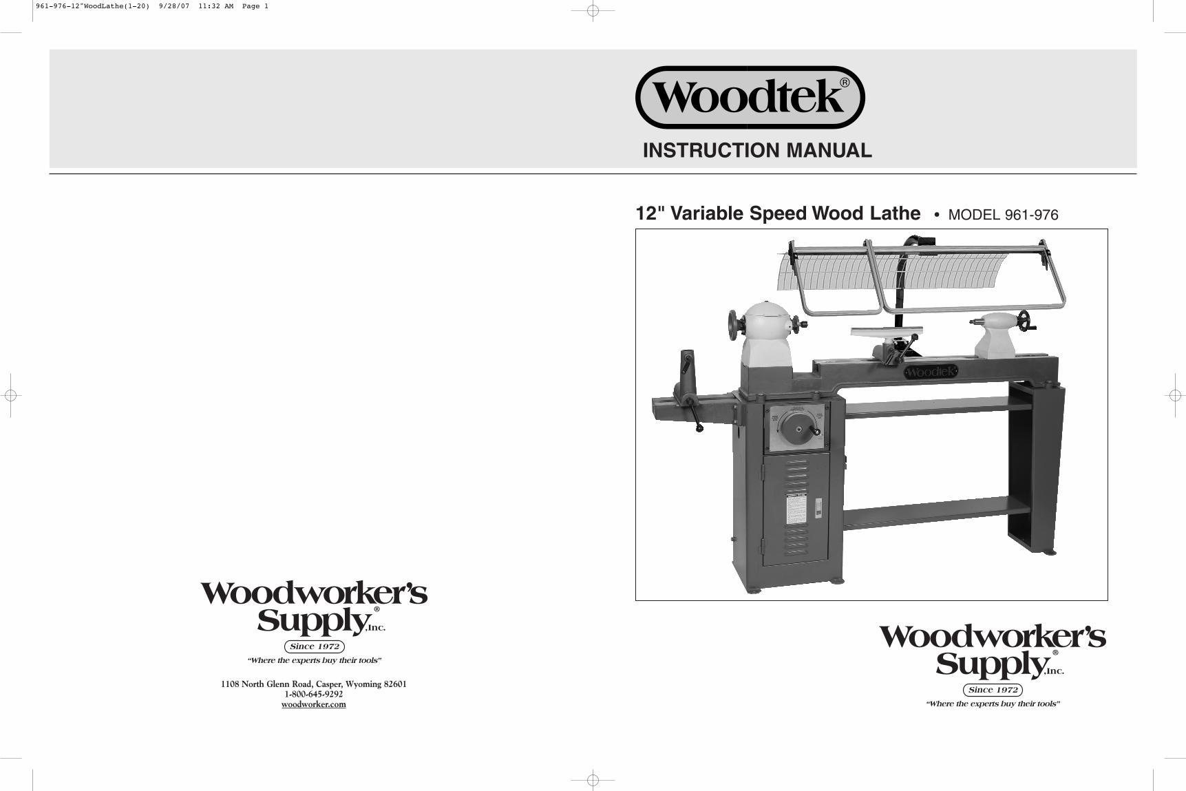
12" Variable Speed Wood Lathe • MODEL 961-976 INSTRUCTION MANUAL 1108 North Glenn Road, Casper, Wyoming 82601 1-800-645-9292 woodworker .com 961-976-12"WoodLathe(1-20) 9/28/07 11:32 AM Page 1
Transcript
12" Variable Speed Wood Lathe • MODEL 961-976
INSTRUCTION MANUAL
1108 North Glenn Road, Casper, Wyoming 826011-800-645-9292
woodworker.com
961-976-12"WoodLathe(1-20) 9/28/07 11:32 AM Page 1
192
WARRANTY AND SERVICE
Woodworker's Supply®, Inc., warrants all machinery and accessory components for a period of 12months from the date of delivery and will replace any products which in normal use have proven tobe defective in materials or workmanship.
This warranty applies only to products used in accordance with the installation, maintenance andoperating instructions set forth in this instruction manual and does not apply to products thatundergo normal wear and tear or products that have undergone misuse, abuse, alteration or repairfrom unauthorized personnel.
This warranty applies provided that the customer notifies Woodworker's Supply®, Inc., of thealleged defect within one year from the date of delivery of the product and provides reasonableopportunity to verify the defect by inspection.
If inspection discloses defects in materials and workmanship, Woodworker's Supply®, Inc., at itsdiscretion, will replace the defective product or refund the purchase price if replacement cannot beprovided quickly. Woodworker’s Supply®, Inc., at its discretion, may require that parts be returnedprepaid to a Woodworker’s Supply® location for inspection.
Under no circumstances will Woodworker's Supply®, Inc., be liable for incidental or consequentialdamages resulting from defective products. This warranty is the sole warranty and sets forth thecustomer's exclusive remedy, with respect to defective products; all other warranties, expressed orimplied, whether of merchantability, fitness for purpose, or otherwise, are expressly disclaimed byWoodworker's Supply®, Inc.
Thoroughly read and understand this manual before operating this equipment. Careshould be taken to follow all safety rules and warning instructions noted throughoutthe manual.
001 HEADSTOCK 1002 PRESSED SPRING 1003 STEEL BALL (D6.0) 1004 "C" SNAP RING (D12) 1005 INDEXING PIN 1006 HEADSTOCK COVER 1009 SPRING WASHER (M8) 4010 HEXAGON BOLT (M8x25L) 4011 BUTTERFLY HINGE 1012 CROSS-HEAD SCREW (M5x10L) 4013 SPINDLE FIXED NUT (1" -8TPI UNC) 1014A HANDWHEEL 1015 BEARING COVER 1016 HEXAGON SOCKET BOLT (M6x25L) 6017 SINGLE ROW BALL BEARING (6205) 2018 LONG SPINDLE SLEEVE 1019 3VA-BELT (42") 1020 SPINDLE BELT PULLEY 1021 SHORT SPINDLE SLEEVE 1022 3" FACEPLATE 1023 ROUND END SQUARE KEY (6x6x30L) 1024 HEADSTOCK SPINDLE 1025 SPUR CENTER, #2 MT 1026 WASHER 4027 RUBBER BUMPER 2028 INFORMATION PLATE 1029 SPINDLE WRENCH 1030 KNOCKOUT ROD 1031 COVER PLUG 1
961-976-12"WoodLathe(1-20) 9/28/07 11:32 AM Page 3
174
1. Read and understand the entire InstructionManual before attempting assembly or operation.
2. Maintain the original location and readability ofall warning labels.
3. Replace all worn or unreadable warning labels.Contact the manufacturer for replacement labels.
4. Read and understand all warnings posted onthis product.
5. Do not use this product for other than itsintended use.
6. Always wear approved safety glasses, faceshields and ear protection.
7. Only properly trained and experienced personnelshould operate this machine.
8. Always wear proper apparel without any loosefitting material that may get caught in machinery.
9. Always keep hair tied back away from movingmachinery.
10. Provide adequate space around the work areaand use non-glare lighting.
11. Do not operate machinery while tired or whileunder the influence of alcohol, drugs or anymedications.
12. Keep visitors and children a safe distance fromthe work area.
13. Keep the workshop childproof by using padlockson master switches and removing starter keys.
14. Keep your work area well ventilated and useproper air filtration systems and dust collectors.
15. Keep the floor around machinery clean and freeof dust, scrap material, oil and grease.
16. Make sure all machinery is properly grounded.17. Make sure all machines are in the “off” position
before connecting to a power supply.18. Do not lean on machinery and maintain a
balanced stance at all times.19. Do not use excessive force to perform machine
operations. All machines are designed forcontrolled operation.
20. Always work with undivided attention.21. Always use the right tools at the correct speed of
operation.22. Never leave a machine running unattended.23. Keep all cutting tools, blades and cutters sharp
for the best performance.24. Unplug machinery from the power source before
making adjustments or for maintenance.25. Make sure all guards are in place before
operation.
26. Repair any damaged machinery parts beforecontinuing operation.
27. Always turn machines off before cleaning.28. Never stand on tools or use a machine for an
unintended use.29. Use recommended accessories to support or
secure work pieces.30. Always maintain tools in top condition for best
performance.
Additional Warnings and Safety Rules
1. Before starting the lathe, always ensure thefollowing: 1) the centers are free of dust anddebris, 2) the tailstock is securely locked downto the lathe bed, 3) the tailstock center is tightinto the workpiece, 4) the tailstock quill lockinglever is tightened, 5) the tool rest levers aretightened, 6) the indexing pin is disengaged.
2. Always check the condition of the workpiecebefore starting the lathe. Do not turn work that isout of balance, or work that has dangerousknots, bark inclusions or poor glue joints.
3. Never drive wood into the drive center in theheadstock. This will damage the bearings.
4. Make sure the tool rest height is adjustedproperly.
5. Always keep the tool rest as close to theworkpiece as possible.
6. Never make any adjustments other thanchanging speed while the lathe is turning.
7. Never adjust the tool rest or tailstock while thelathe is turning.
8. Ensure proper lubrication when using a cup ordead center.
9. Always use the appropriate size faceplate.10. Always fasten the workpiece securely to the
faceplate.11. Always rough-cut the workpiece as closely as
possible to the finished shape and ensure properbalance before turning.
12. Before starting, rotate work by hand first toensure clearance of all lathe components.
13. Always start the lathe with the speed turned offand gradually increase to desired speed.
14. Never wear gloves while turning or sanding.15. Always remove the tool rest when sanding.
WARNINGS
001 LATHE BED 1002 HEADSTOCK CABINET 1003 HEADSTOCK CABINET DOOR 1004 CABINET CROSS SUPPORT TOOL TRAYS 2005 TAILSTOCK CABINET STAND 1006 OUTBOARD BED 1007 12" TOOL REST 1008 OUTBOARD TOOLREST BASE 1009 TOOLREST LOCKING HANDLE 2010 FIXED SCREW 2011 OUTBOARD TOOLREST EYE BOLT 2012 TOOL REST LOCKING SHAFT 2013 TOOLREST LOCKING BLOCK 2014 TOOLREST BASE LOCKING HANDLE 2015 TOOLREST HANDLE KNOB 2016 INBOARD TOOLREST BASE 1017 WASHER (M10x20Dx2.0t) 4018 HEXAGON BOLT (M8x75L) 4019 SPRING WASHER (M8) 9020 SPRING WASHER (M12) 6021 HEXAGON BOLT (M12x50L) 6022 HEXAGON BOLT (M8x20L) 8023 WASHER (M8x23Dx2.2t) 9024 MOTOR MOUNTING PLATE 1025 HEXAGON BOLT (M10x25l) 6026 WASHER 10027 WASHER (M10x26Dx2.5t) 2028 MOTOR MOUNTING PLATE SUPPORT SHAFT 1029 MOTOR BELT LOCKING EYE BOLT 1030 NUT (M8) 8031 MOTOR BELT ADJUSTING SCREW 1032 MOTOR 1033 ROUND END SQUARE KEY (5x5x30L) 1034 SPRING WASHER (M10) 4035 MOTOR SHAFT PULLEY BELT 1036 FIXED SCREW (M8x8L) 3037 3VA-BELT (42") 1038 VARIABLE SPEED FIXED SUPPORTER 1039 HEXAGON SOCKET BOLT (M8x30L) 5040 SPEED CHANGE INDICATOR PLATE 1041 VARIABLE TRANSMISSION WORM SCREW 1042 ROUND END SQUARE KEY (4x4x8L) 1
REFNO. DESCRIPTION QTY
REFNO. DESCRIPTION QTY
PARTS LIST (A)
043 TURNPLATE SWIVEL HANDLE 1044 VARIABLE SPEED CONTROL TURNPLATE 1045 HEXAGON SOCKET BOLT (M6x10L) 1046 WASHER (M6 x19Dx1.6t) 1047 PRESSED SPRING 1048 SWING ARM FIXED SHAFT 1049 ROUND END SQUARE KEY (5x5x60L) 1050 VARIABLE TRANSMISSION BEVEL GEAR 1051 SWING ARM PULLEY SHAFT 1052 GREASE NIPPLE (M8xP1.0) 1053 "C" SNAP RING (D20) 2054 NEEDLE BEARING (2016) 2055 VARIABLE SPEED SHAFT THIMBLE 1056 INNER SPEED CHANGE SHEAVE 2057 OUTER SPEED CHANGE SHEAVE 2058 ROLL PIN 2059 SPEED CHANGE SHEAVE BUSHING 1060 SWITCH COVER PLATE 1061 START/STOP SWITCH 1062 CROSS-HEAD SCREW (M4x25L) 2063 DOOR LOCK 1064 SCALE FIXING SCREW 4065 SPEED CHANGE SCALE ARM 1066 "L" VARIABLE SPEED SWING ARM 1067 SWING ARM STOP NUT 1068 DOOR HINGE PIN 2069 SPEED CHANGE SCALE 1070 CABINET GROMET 1071 COTOR CORD 1072 MOTOR LEAD 1073 SHEAVE SET SCREW 2074 NUT (M4) 2075 NUT 4076 CABINET DOOP STOP PAD 1077 FIXED SCREW 1078 SWITCH BOX 1079 FIXED SHAFT KEEPER SET SCREW 1080 LEVELING SCREW JAMB NUT 2081 LEVELING SCREW 2082 TOOL REST LOCKNUT 2083 WASHER 2084 OFF SWITCH PADDLE 1
961-976-12"WoodLathe(1-20) 9/28/07 11:32 AM Page 4
516
DIAMETER ROUGHING GENERAL FINISHINGUnder 2" 1500 2100 21002" to 4" 750 1600 21004" to 6" 500 1050 16506" to 8" 375 800 12508" to 10" 300 650 100010" to 12" 250 550 850
16. Use slow speeds for roughing long and largediameter work and higher speeds for generalcutting and finishing work – see speedrecommendation chart below.
17. Do not engage the indexing pin while the lathe isturning.
18. Never grab the workpiece to slow it down whilethe lathe is stopping.
WARNINGS
SPEED RECOMMENDATIONS (RPM)
Some dusts created by woodworking activities may contain chemicals known to causecancer, birth defects, reproductive disease, respiratory disease and skin allergies.Chemicals include: arsenic, chromium and formaldehyde from chemically treatedlumber and building materials; crystalline silica from masonry products; lead fromlead-based products; and quinones, alkaloids and glycosides from some exotichardwoods.
Warning
SCHEMATIC (A) – LATHE CABINET
961-976-12"WoodLathe(1-20) 9/28/07 11:32 AM Page 5
Note: Specifications, while deemed accurate, are subject to change without notice.
TROUBLESHOOTING
PROBLEM POSSIBLE CAUSE SOLUTION
No power 1. Fuse blown or circuit breaker tripped 1. Replace fuse, reset breaker2. Indexing pin is engaged 2. Disengage indexing pin3. Electric cord damaged 3. Replace electric cord4. Defective belt 4. Replace belt5. Defective motor 5. Replace motor
Excessive vibration 1. Workpiece out of balance 1. Balance workpiece prior to turning2. Defective bearings 2. Replace bearings3. Worn or defective belt 3. Replace belt4. Defective motor 4. Replace motor5. Bent pulley 5. Replace pulley6. Improper motor mounting 6. Adjust motor mounting
Motor overheats 1. Motor overloaded 1. Correct overload condition2. Improper motor cooling 2. Clean dust from motor
Motor fails to develop power 1. Motor not wired for correct voltage 1. Wire motor correctly2. Supplied wires undersized 2. Use correct sized wiring3. Low voltage 3. Request voltage check4. Low current 4. Correct low current condition5. Defective motor 5. Replace motor
Tools grab or dig into work 1. Tool rest set too far from work 1. Position tool rest close to work2. Too aggressive of a cut 2. Moderate depth of cut3. Improper tool use 3. Use proper tool for type of cut4. Improper cutting techniques 4. Use proper cutting techniques
Tool chatters on workpiece 1. Tool rest set too far from work 1. Position tool rest close to work2. Improper tool for cut 2. Use proper tool3. Tool too dull 3. Sharpen tool4. Bearings worn 4. Replace bearings
Cup center burns 1. Cup center improperly lubricated 1. Lubricate cup center, use atailstock live center
Tool rest base creeps 1. Tool rest base not tight 1. Tighten tool rest base2. Too aggressive a cut 2. Moderate depth of cut3. Heavy tool impacts from unbalanced 3. Balance workpiece prior to
workpiece mounting on lathe; use lighter cuts
961-976-12"WoodLathe(1-20) 9/28/07 11:32 AM Page 6
714
Bowl Turning
PreviewThere are many different turning accessories usedfor mounting wood on a lathe. This example coversone procedure using a 3" faceplate and a 4-jawedchuck with 1" x 8TPI spindle threads to fit this lathe.
Preparing the wood for turning1. Wood selected for bowl turning can come from
many sources including trunks, branches, rootsand burls. For this example, select a piece offairly dry wood about 8" in diameter and 3"thick.
2. Mark the center of the top of the bowl blank anddraw a circle the diameter of the faceplate witha compass.
3. Center and screw the faceplate on the top of thebowl and mount the turning blank on theinboard spindle. The bottom of the bowl will befacing outward.
Turning the bowl1. With a 1/2" bowl gouge turned over on its side
and the flutes facing the direction of the cut, trueup the outside of the bowl at the speedindicated on the Speed Chart.
2. Keep the bevel of the gouge running close tothe wood.
3. Remove the bulk of the waste wood from thelower outside part of the bowl.
4. Define the outside shape of the bowl leavingenough room on the bottom for a raised foot.
5. Turn a recess dovetail on the bottom of the bowlto accept the internal chuck jaws.
6. Remove the bowl from the lathe and remove thefaceplate.
7. Put the chuck on the lathe and mount thebottom of the bowl on the chuck.
8. Turn the inside of the bowl with a 1/2" bowlgouge to a thickness of about 3/4". Start in themiddle of the bowl and turn away a small hollow.
9. Each successive cut should start further outtoward the rim and move down and into thecenter of the bowl.
10. Continue in this manner until the bowl iscompletely hollowed out with a wall thickness ofabout 3/4".
11. Leave a raised center inside the bottom of thebowl and cut a recess dovetail to accept internalchuck jaws after seasoning.
12. Remove the bowl blank from the lathe and let itdry. This may take several weeks or months
INSTALLATION
UnpackingThe Woodtek 12" Wood Lathe comes mostly assembled in the packing crate. Prior to unpacking,make a note of any damage to the packing crate. Immediately report any damage to the distributorwhere you purchased the lathe. Carefully open the crate and inspect the lathe for any damage thatmay have occurred during shipping. Immediately report any damage to the lathe to the distributorwhere you purchased the lathe.
CleaningClean protective oil or grease from the surface of the lathe with a mild solvent or kerosene. DONOT use lacquer thinner, paint thinner or gasoline. This could damage the painted surfaces andrubber components. Use soap and water on painted surfaces and rubber components. Ensure thatall components are clean and move freely without restriction.
LocationLocate the lathe where there will be sufficient working room around the lathe. A minimum of sixfeet of working room completely around the lathe is recommended. Ensure adequate overheadlighting for all working positions around the lathe. Since airborne dust is a constant hazard with awood lathe, consideration should be given to lathe location relative to an exhaust system.
WiringThe Woodtek 12" Wood Lathe comes wired for 120V operation but can be wired for either 120V or240V. See wiring diagram below for wiring positions. Repositioning leads 5 and 6 in either 120V or240V will reverse the direction of motor rotation.
depending on how wet the wood is.13. Once dried, remount the bowl using the dovetail
inside the bowl and true up the outside shape ofthe bowl
14. Turn a desired profile for the foot on the bottomof the bowl and true up the bottom recessdovetail.
15. Completely sand the outside of the bowlincluding the foot and recess dovetail.
16. Remove the bowl from the lathe and remountthe bowl on the lathe using the bottom recessdovetail.
17. Finish turning the inside of the bowl with longshearing cuts from the rim to the bottom of thebowl. As the wall thickness decreases use asmaller 3/8" fingernail gouge for better control.Keep the wall from vibrating by providing handsupport or using a bowl steady.
18. Completely sand the inside of the bowl. Finishon or off the lathe as desired.
961-976-12"WoodLathe(1-20) 9/28/07 11:32 AM Page 7
138
1. Lathe Bed
2. Tailstock Handwheel
3. Tailstock
4. Tailstock Center
5. Safety Shield
6. 12" Tool Rest
7. Inboard Tool Rest Base
8. Inboard Spindle
9. Indexing/Shaft Locking Pin
10. Headstock
11. Handwheel
12. Outboard Tool Rest
13. Outboard Bed
14. Variable Speed Control
15. Lathe Cabinet
16. Master On/Off Switch
17. Bed End Gap
18. Tool Trays
BASIC COMPONENTS
10 896
7
5 4 3
2
1
17
14
18
13
11
12
16
15
Spindle Turning
Preparing wood for turning1. Wood selected for spindle turning should be
straight grained and free from knots anddefects.
2. Mark the center point on both ends of the woodwith a center finder or similar marker and puncha dimple with an awl or nail.
3. Drive the spur center into one end with awooden mallet. If the wood is very hard, cutperpendicular kerfs through the center pointwith a bandsaw or handsaw before setting theprongs into the wood.
Mounting the wood on the lathe1. Put a live center or cup center into the tailstock.
If using a cup center, put a small dab of greaseor oil onto the end of the cup center.
2. Put the spur drive center into the headstockspindle and align the prong marks in the woodwith the prongs in the spur center.
3. Bring the tailstock up to contact the center pointin the wood and tighten the tailstock to the bed.
4. Turn the tailstock quill handwheel until the woodis tight between centers.
Roughing out the workpiece1. Position the tool rest about 1/8" below the
center line of the spindle and about 1/4" awayfrom he workpiece.
2. Round the spindle with a roughing gougeground to a 30° angle moving back and forthwith the gouge slightly turned up on its side.
3. Never start from the end of a workpiece andalways work down hill from the wider tonarrower portion of the turning.
4. For the final cut, keep the indexing finger in thecurved notch in the tool rest and move thegouge in one continuous motion along thelength of the tool rest.
Making beads and coves1. Beads and coves are generally cut with a
spindle or detail gouge. Define the outside endsof the bead by making a parting cut on eitherside to the depth of the desired bead.
2. Roll and turn the gouge from the top center ofthe bead down and in toward either side of thebead. Cut with the tip of the gouge and makesure the bevel of the gouge is flat against thebead. Make repeated cuts until the desired beadis produced.
3. Define the ends of the cove by marking thespindle with a pencil while the workpiece isspinning.
4. Make the coving cut by rolling the gouge fromthe side into the center of the cove. Move fromside to side keeping the dimension of the coveuniform.
Making parting and taper cuts1. Parting cuts are made with narrow chisel or
diamond shaped parting tools. These cuts arestraight plunge cuts into wood to a selecteddepth.
2. Taper and "V" cuts are usually made with askew chisel. Mark either side of the “V”. Keepingthe bevel of the skew parallel to the cut, make atapering cut by moving the point end of the skewdown and into the bottom of the taper.
961-976-12"WoodLathe(1-20) 9/28/07 11:32 AM Page 8
912
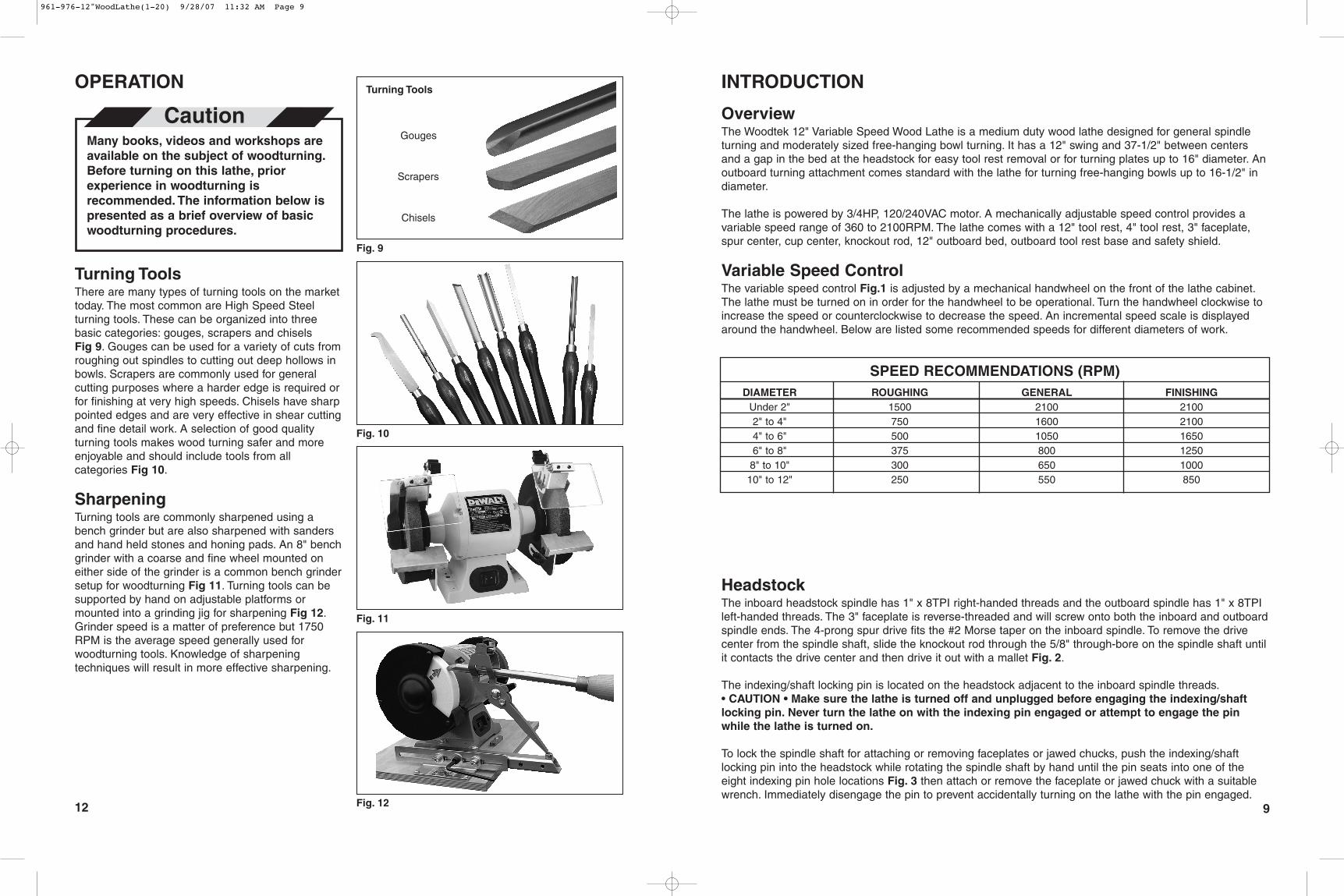
Turning ToolsThere are many types of turning tools on the markettoday. The most common are High Speed Steelturning tools. These can be organized into threebasic categories: gouges, scrapers and chiselsFig 9. Gouges can be used for a variety of cuts fromroughing out spindles to cutting out deep hollows inbowls. Scrapers are commonly used for generalcutting purposes where a harder edge is required orfor finishing at very high speeds. Chisels have sharppointed edges and are very effective in shear cuttingand fine detail work. A selection of good qualityturning tools makes wood turning safer and moreenjoyable and should include tools from allcategories Fig 10.
SharpeningTurning tools are commonly sharpened using abench grinder but are also sharpened with sandersand hand held stones and honing pads. An 8" benchgrinder with a coarse and fine wheel mounted oneither side of the grinder is a common bench grindersetup for woodturning Fig 11. Turning tools can besupported by hand on adjustable platforms ormounted into a grinding jig for sharpening Fig 12.Grinder speed is a matter of preference but 1750RPM is the average speed generally used forwoodturning tools. Knowledge of sharpeningtechniques will result in more effective sharpening.
OverviewThe Woodtek 12" Variable Speed Wood Lathe is a medium duty wood lathe designed for general spindleturning and moderately sized free-hanging bowl turning. It has a 12" swing and 37-1/2" between centersand a gap in the bed at the headstock for easy tool rest removal or for turning plates up to 16" diameter. Anoutboard turning attachment comes standard with the lathe for turning free-hanging bowls up to 16-1/2" indiameter.
The lathe is powered by 3/4HP, 120/240VAC motor. A mechanically adjustable speed control provides avariable speed range of 360 to 2100RPM. The lathe comes with a 12" tool rest, 4" tool rest, 3" faceplate,spur center, cup center, knockout rod, 12" outboard bed, outboard tool rest base and safety shield.
Variable Speed ControlThe variable speed control Fig.1 is adjusted by a mechanical handwheel on the front of the lathe cabinet.The lathe must be turned on in order for the handwheel to be operational. Turn the handwheel clockwise toincrease the speed or counterclockwise to decrease the speed. An incremental speed scale is displayedaround the handwheel. Below are listed some recommended speeds for different diameters of work.
HeadstockThe inboard headstock spindle has 1" x 8TPI right-handed threads and the outboard spindle has 1" x 8TPIleft-handed threads. The 3" faceplate is reverse-threaded and will screw onto both the inboard and outboardspindle ends. The 4-prong spur drive fits the #2 Morse taper on the inboard spindle. To remove the drivecenter from the spindle shaft, slide the knockout rod through the 5/8" through-bore on the spindle shaft untilit contacts the drive center and then drive it out with a mallet Fig. 2.
The indexing/shaft locking pin is located on the headstock adjacent to the inboard spindle threads.• CAUTION • Make sure the lathe is turned off and unplugged before engaging the indexing/shaftlocking pin. Never turn the lathe on with the indexing pin engaged or attempt to engage the pinwhile the lathe is turned on.
To lock the spindle shaft for attaching or removing faceplates or jawed chucks, push the indexing/shaftlocking pin into the headstock while rotating the spindle shaft by hand until the pin seats into one of theeight indexing pin hole locations Fig. 3 then attach or remove the faceplate or jawed chuck with a suitablewrench. Immediately disengage the pin to prevent accidentally turning on the lathe with the pin engaged.
OPERATION INTRODUCTION
Many books, videos and workshops areavailable on the subject of woodturning.Before turning on this lathe, priorexperience in woodturning isrecommended. The information below ispresented as a brief overview of basicwoodturning procedures.
Caution
Fig. 9
Fig. 10
Gouges
Scrapers
Chisels
Fig. 11
Fig. 12
DIAMETER ROUGHING GENERAL FINISHINGUnder 2" 1500 2100 21002" to 4" 750 1600 21004" to 6" 500 1050 16506" to 8" 375 800 12508" to 10" 300 650 100010" to 12" 250 550 850
SPEED RECOMMENDATIONS (RPM)
Turning Tools
961-976-12"WoodLathe(1-20) 9/28/07 11:32 AM Page 9
1110
TailstockThe tailstock locking handle on the side of the tailstock tightens the tailstock against the bed ways. Itsrotational position is factory set but if it needs to be adjusted, lightly turn the locking nut under the lockingplate on the bottom of the tailstock to increase or decrease the tension Fig. 4. The tailstock handwheelmoves the tailstock center into the workpiece. To tighten the center, loosen the quill locking handle on theside of the quill housing and turn the handwheel clockwise moving the center into the workpiece. Thentighten the quill locking handle. To remove the center from the quill, turn the tailstock handwheelcounterclockwise all the way until the center self-ejects Fig. 5.
Tool RestThe tool rest base locking handle on the end of the tool rest base tightens and loosens the base against thebed ways. Its rotational position can be adjusted similar to the tailstock above. The tool rest is locked to thebase with the tool rest locking handle on the side of the tool rest base Fig. 6.
Outboard AttachmentThe outboard bed attachment Fig. 7 consists of the outboard tool rest base and the outboard bed andprovides support for outboard bowl turning. The outboard attachment does not come attached to the lathe.To attach, bolt the bed to the cabinet and slide the outboard tool rest base onto the bed. The outboard toolrest base operates in the same manner as the inboard tool rest base. The 4" and 12" tool rests fits both theinboard and outboard tool rest bases.
Optional Lathe DuplicatorThe Woodtek® Lathe Duplicator (Model 140-069) Fig. 8 is an optional piece of equipment specificallydesigned as a companion to the 12" Woodtek® Wood Lathe. This duplicator attaches to the bed of the latheand is operated by a jam-free, cable-driven carriage system. Sample spindles or templates are mountedonto the side of the duplicator where a pilot shaft follows the form of the turning or template. This duplicatorcan make copies of spindles up to 39" long and can also copy open faceplate turnings when mountedperpendicular to the lathe bed ways. Complete mounting and operating instructions are included with theduplicator.
Fig. 1
Variable speed control
Fig. 3
Fig. 5
Fig. 7
Fig. 2
Fig. 4
Fig. 6
Fig. 8
Ejecting spur centers
Ejecting tailstock centers
Tool rest lockingIndexing
Tool rest
Outboardattachment
Optional lathe duplicator
Locknut
961-976-12"WoodLathe(1-20) 9/28/07 11:32 AM Page 10