154
Instruction MI 020-504 February 2016 PC50 Intelligent Field Device Tool Operation Using FoxCom Communication Protocol

Instruction MI 020-504February 2016
PC50 Intelligent Field Device Tool
Operation Using FoxCom Communication Protocol

MI 020-504 – February 2016
2

Contents
Figures ........................................................................................................................................... 9
Tables .......................................................................................................................................... 13
Preface ......................................................................................................................................... 15
1. Common Information ............................................................................................................. 17
Right Click Menus....................................................................................................................17
Diagnosis ..................................................................................................................................17
Trend Viewer.............................................................................................................................18Load.....................................................................................................................................19Save......................................................................................................................................19Print .....................................................................................................................................19Export ..................................................................................................................................19Clear ....................................................................................................................................20
Set mA Function .......................................................................................................................20
Set Digital Output Function .....................................................................................................21
Mode Change Function ............................................................................................................21
Display Raw Input Function .....................................................................................................21
Configuration Function ............................................................................................................22Saving Configuration Changes .............................................................................................22Entering Tag Numbers .........................................................................................................22
Print..........................................................................................................................................22
2. I/A Series Pressure Transmitters .............................................................................................. 23
Measure Screen .........................................................................................................................23
Error Messages ..........................................................................................................................24Status Error Messages ...........................................................................................................24Diagnostic Error Messages....................................................................................................24
Calibration................................................................................................................................25Re-Zero................................................................................................................................26Point Calibration..................................................................................................................27Re-Range..............................................................................................................................28Restore Default.....................................................................................................................29mA Calibration ....................................................................................................................29
3

MI 020-504 – Februray 2016 Contents
Configuration ...........................................................................................................................30Identifier Tab Screen.............................................................................................................30Transmitter Parameter Configuration Tab Screen .................................................................31
3. RTT20/TI20 Temperature Transmitters ................................................................................. 33
Measure Screen .........................................................................................................................33
Error Messages ..........................................................................................................................34
Calibration................................................................................................................................35N-Point Calibration .............................................................................................................35
1-Point Calibration..........................................................................................................352-Point Calibration..........................................................................................................353- and 5- Point Calibration..............................................................................................35N-Point Calibration Procedure ........................................................................................36
Custom Input Curve ............................................................................................................37ReRange ...............................................................................................................................39Restore Factory.....................................................................................................................39mA Calibration ....................................................................................................................40
Configuration ...........................................................................................................................42Identifier Tab Screen.............................................................................................................42Input Tab Screen ..................................................................................................................43Options Tab Screen ..............................................................................................................44Display Tab Screen ...............................................................................................................45
4. IMT25 and IMT25L Magnetic Flow Transmitters.................................................................. 47
Measure Screen .........................................................................................................................47
Error Messages ..........................................................................................................................47
Calibration................................................................................................................................49Empty Pipe ..........................................................................................................................49mA Output ..........................................................................................................................50Reset Totals ..........................................................................................................................51
Configuration ...........................................................................................................................51Identifier Tab Screen.............................................................................................................52Flow Tab Screen ................................................................................................................53Alarms Tab Screen ................................................................................................................54Contacts Tab Screen ............................................................................................................55Options Tab Screen ..............................................................................................................56Display/Totalizer Tab Screen ................................................................................................57
4
Contents MI 020-504 – Februray 2016
5. IMT96 Magnetic Flow Transmitters ....................................................................................... 59
Measure Screen .........................................................................................................................59
Error Messages ..........................................................................................................................60
Calibration................................................................................................................................61Zero Flow Calibration ..........................................................................................................61Restore Zero Flow Default....................................................................................................62Reset Totals ..........................................................................................................................63mA Output ..........................................................................................................................64
Configuration ...........................................................................................................................65Identifier Tab Screen.............................................................................................................65Flow Tab Screen ................................................................................................................66Alarms Tab Screen ................................................................................................................67Contacts Tab Screen .............................................................................................................68Options Tab Screen ..............................................................................................................69Display/Totalizer Tab Screen ................................................................................................70
6. 83 Series Vortex Flowmeters .................................................................................................... 71
Measure Screen .........................................................................................................................71
Error Messages ..........................................................................................................................72Status Error Messages ...........................................................................................................72Diagnostic Error Messages....................................................................................................73
Calibration................................................................................................................................73Set Low Flow Cut-In ............................................................................................................74Re-Range..............................................................................................................................75Zero Total.............................................................................................................................75mA Calibration ....................................................................................................................76
Configuration ...........................................................................................................................77Identifier Tab Screen.............................................................................................................77Flow Parameters Tab Screen .................................................................................................78Options and Piping Tab Screen ............................................................................................79
7. 870ITEC Transmitters ............................................................................................................ 81
Measure Screen .........................................................................................................................81
Error Messages ..........................................................................................................................81
Calibration................................................................................................................................83Bench Calibration ................................................................................................................84Solution 1-Point Offset ........................................................................................................85Solution 1-Point Span ..........................................................................................................86Solution 2-Point ...................................................................................................................87Temperature Sensor Calibration ...........................................................................................88mA Calibration ....................................................................................................................89
5

MI 020-504 – Februray 2016 Contents
Configuration ...........................................................................................................................90Identifier Tab Screen.............................................................................................................90Sensor Tab Screen.................................................................................................................91Measurement Tab Screen......................................................................................................92Misc Tab Screen ...................................................................................................................93Application Tab Screen.........................................................................................................94
8. 870ITPH pH/ORP/ISE Transmitters ..................................................................................... 97
Measure Screen .........................................................................................................................97
Error Messages ..........................................................................................................................97
Calibration..............................................................................................................................100One Point Manual Calibration ...........................................................................................101One Point Absolute Calibration .........................................................................................102Two Point Manual Calibration ...........................................................................................103mA Calibration ..................................................................................................................104Automatic Calibration........................................................................................................105Temperature Sensor ............................................................................................................106
Configuration .........................................................................................................................107Identifier Tab Screen...........................................................................................................107Sensor Tab Screen...............................................................................................................108Output Tab Screen .............................................................................................................111Measurement Tab Screen....................................................................................................112Diagnostic Tab Screen ........................................................................................................113
9. 870ITCR Conductivity/Resistivity Transmitters ................................................................... 115
Measure Screen .......................................................................................................................115
Error Messages ........................................................................................................................116
Calibration..............................................................................................................................117Solution 1-Point Offset ......................................................................................................118Solution 1-Point Span ........................................................................................................119Solution 2-Point .................................................................................................................120Bench Calibration ..............................................................................................................121Calibration Pure H2O........................................................................................................121Temperature Sensor ............................................................................................................122mA Calibration ..................................................................................................................123
Configuration .........................................................................................................................124Identifier Tab Screen...........................................................................................................124Sensor Tab Screen...............................................................................................................125Measurement Tab Screen....................................................................................................126Misc Tab Screen .................................................................................................................127Application Tab Screen ......................................................................................................128
6
Contents MI 020-504 – Februray 2016
10. Intelligent Positioners (SRD991, SRD960, SRD970, NAF-LinkIT) ................................... 131
Measure Screen .......................................................................................................................131
Status Error Messages ..............................................................................................................132
Calibration..............................................................................................................................133Autostart Calibration..........................................................................................................133Endpoints Calibration ........................................................................................................134Analog Setpoint Calibration ...............................................................................................134Angle Calibration ...............................................................................................................135Temperature Calibration ....................................................................................................135Position Feedback Calibration ............................................................................................136Air Supply Pressure Calibration ..........................................................................................136Output Pressure Calibration...............................................................................................136Restore Valve-Specific Parameter ........................................................................................137Restore Factory Settings......................................................................................................137
Mode Change .........................................................................................................................137On-Line .............................................................................................................................137Off-Line .............................................................................................................................137Local Mode ........................................................................................................................137Calibrate.............................................................................................................................138Factory ...............................................................................................................................138
Reset Status .............................................................................................................................138
Reset Counters ........................................................................................................................138
Reset Device............................................................................................................................138
Write Protect...........................................................................................................................138
Configuration .........................................................................................................................139Identifier Tab Screen...........................................................................................................139Parameters Tab Screen ........................................................................................................140Configuration Tab Screen ..................................................................................................141Characterization Tab Screen ...............................................................................................142Travel Tab Screen................................................................................................................143Alarms Tab Screen ..............................................................................................................144Tuning Tab Screen..............................................................................................................145Pressure Tab Screen ............................................................................................................146Options Tab Screen ............................................................................................................147Bin In Tab Screen ...............................................................................................................148Bin Out Tab Screen ............................................................................................................149
Index ......................................................................................................................................... 151
7

MI 020-504 – Februray 2016 Contents
8
Figures
1 Sample Diagnosis Screen .....................................................................................................172 Sample Diagnostic Codes Screen.........................................................................................183 Sample Trend Viewer Screen ...............................................................................................184 Sample Set mA or Set Digital Output Screen ......................................................................205 Sample I/A Series Pressure Transmitter Measure Screen .......................................................236 Sample I/A Series Pressure Transmitter Re-Zero or Point Calibration Screen .......................277 Sample I/A Series Pressure Transmitter Re-Range Screen.....................................................288 Sample I/A Series Pressure Transmitter mA Calibration Screen............................................299 Sample I/A Series Pressure Transmitter Identifier Tab Screen ...............................................30
10 Sample I/A Series Pressure Transmitter Parameter Configuration Tab Screen.......................3111 Sample RTT20 Measure Screen ..........................................................................................3312 Sample RTT20 N-Point Calibration Screen ........................................................................3613 Sample RTT20 Custom Input Curve Screen.......................................................................3714 Sample RTT20 ReRange Screen..........................................................................................3915 Sample RTT20 Restore Factory Calibration Screen.............................................................4016 Sample RTT20 mA Calibration Screen (FoxCom Device) ..................................................4117 Sample RTT20 Identifier Tab Screen ..................................................................................4218 Sample RTT20 Input Tab Screen ........................................................................................4319 Sample RTT20 Options Tab Screen ....................................................................................4420 Sample RTT20 Display Tab Screen .....................................................................................4521 Sample IMT25 Measure Screen ..........................................................................................4722 Sample IMT25 mA Calibration Screen ...............................................................................5023 Sample IMT25 Reset Totals Screen .....................................................................................5124 Sample IMT25 Identifier Tab Screen ..................................................................................5225 Sample IMT25 Flow Tab Screen .........................................................................................5326 Sample IMT25 Alarms Tab Screen ......................................................................................5427 Sample IMT25 Contacts Tab Screen ...................................................................................5528 Sample IMT25 Options Tab Screen ....................................................................................5629 Sample IMT25 Display/Totalizer Tab Screen ......................................................................5730 Sample IMT96 Measure Screen ..........................................................................................5931 Sample IMT96 Reset Totals Screen .....................................................................................6332 Sample IMT96 mA Calibration Screen ...............................................................................6433 Sample IMT96 Identifier Tab Screen ..................................................................................6534 Sample IMT96 Flow Tab Screen .........................................................................................6635 Sample IMT96 Alarms Tab Screen ......................................................................................6736 Sample IMT96 Contacts Tab Screen ...................................................................................6837 Sample IMT96 Options Tab Screen ....................................................................................6938 Sample IMT96 Display/Totalizer Tab Screen ......................................................................7039 Sample Vortex Measure Screen ............................................................................................7140 Sample Vortex Low Flow Cut-In Screen ..............................................................................7441 Sample Vortex Re-Range Screen ..........................................................................................7542 Sample Vortex mA Calibration Screen.................................................................................7643 Sample Vortex Flowmeter Identifier Tab Screen...................................................................77
9
MI 020-504 – February 2016 Figures
44 Sample Vortex Flow Parameters Tab Screen .........................................................................7845 Sample Vortex Options and Piping Tab Screen....................................................................7946 Sample 870ITEC Measure Screen .......................................................................................8147 Sample 870ITEC Bench Calibration Screen........................................................................8448 Sample 870ITEC Solution 1-Point Offset Screen................................................................8549 Sample 870ITEC Solution 1-Point Span Screen..................................................................8650 Sample 870ITEC Solution 2-Point Calibration Screen........................................................8751 Sample 870ITEC Temperature Calibration .........................................................................8852 Sample 870ITEC mA Calibration Screen............................................................................8953 Sample 870ITEC Identifier Tab Screen ...............................................................................9054 Sample 870ITEC Sensor Tab Screen ...................................................................................9155 Sample 870ITEC Measurement Tab Screen ........................................................................9256 Sample 870ITEC Misc Tab Screen......................................................................................9357 Sample 870ITEC App1 Tab Screen.....................................................................................9458 Custom Chemical Compensation Screen ............................................................................9559 Custom Temperature Compensation Screen........................................................................9560 Sample 870ITPH Measure Screen.......................................................................................9761 Sample 870ITPH One Point Manual Calibration Screen ..................................................10162 Sample 870ITPH One Point Absolute Calibration Screen ................................................10263 Sample 870ITPH Two Point Manual Calibration Screen ..................................................10364 Sample 870ITPH mA Calibration Screen .........................................................................10465 Sample 870ITPH Temperature Calibration Screen............................................................10666 Sample 870ITPH Identifier Tab Screen.............................................................................10767 Sample 870ITPH Sensor Tab Screen .................................................................................10868 Custom Buffers Screen ......................................................................................................10969 Custom Temperature Compensation Screen......................................................................10970 Custom Chemical Compensation Screen ..........................................................................11071 Sample 870ITPH Output Tab Screen ...............................................................................11172 Sample 870ITPH Measurement Tab Screen ......................................................................11273 Sample 870ITPH Diagnostic Tab Screen ..........................................................................11374 Sample 870ITCR Measure Screen.....................................................................................11575 Sample 870ITCR Solution 1-Point Offset Screen..............................................................11876 Sample 870ITCR Solution 1-Point Span Screen ...............................................................11977 Sample 870ITCR Solution 2-Point Calibration Screen .....................................................12078 Sample 870ITCR Temperature Calibration.......................................................................12279 Sample 870ITCR mA Calibration Screen..........................................................................12380 Sample 870ITCR Identifier Tab Screen.............................................................................12481 Sample 870ITCR Sensor Tab Screen .................................................................................12582 Sample 870ITCR Measurement Tab Screen ......................................................................12683 Sample 870ITCR Misc Tab Screen....................................................................................12784 Sample 870ITCR App1 Tab Screen...................................................................................12885 Custom Chemical Compensation Screen ..........................................................................12986 Custom Temperature Compensation Screen......................................................................12987 Sample SRD991 Device Data Screen ................................................................................13188 Sample SRD991 Identifier Tab Screen ..............................................................................13989 Sample SRD991 Parameters Tab Screen ............................................................................14090 Sample SRD991 Configuration Tab Screen.......................................................................14191 Sample SRD991 Characterization Tab Screen ...................................................................142
10

Figures MI 020-504 – February 2016
92 Sample SRD991 Travel Tab Screen....................................................................................14393 Sample SRD991 Alarms Tab Screen ..................................................................................14494 Sample SRD991 Tuning Tab Screen..................................................................................14595 Sample SRD991 Pressure Tab Screen ................................................................................14696 Sample SRD991 Options Tab Screen ................................................................................14797 Sample SRD991 Bin In Tab Screen...................................................................................14898 Sample SRD991 Bin Out Tab Screen................................................................................149
11

MI 020-504 – February 2016 Figures
12

Tables
1 Raw Inputs Displayed for Various Devices ..........................................................................212 Reference Documents .........................................................................................................233 Transmitter Status Error Messages .......................................................................................244 Transmitter Diagnostic Error Messages................................................................................255 Transmitter Status Error Messages .......................................................................................346 Transmitter Status Error Messages .......................................................................................487 Transmitter Status Error Messages .......................................................................................608 Status Error Messages ..........................................................................................................729 Diagnostic Error Messages...................................................................................................73
10 Transmitter Status Error Messages .......................................................................................8211 Transmitter Status Error Messages .......................................................................................9812 Transmitter Status Error Messages .....................................................................................11613 Field Device Status Error Messages....................................................................................132
13

MI 020-504 – February 2016 Tables
14
Preface
This manual explains how to operate, calibrate, and configure devices having a FoxCom communication protocol with the PC50 Field Device Tool software package.
Chapter 1 provides information that is common to using the PC50 Field Device Tool with various transmitters with FoxCom communication protocol. This is followed by chapters on each Foxboro Intelligent Device. These chapters show an example of the device’s data screen, gives an explanation of the device’s status/diagnostic error messages with recommended actions, and explains how to calibrate and configure the device.
Therefore, to use this manual, refer to Chapter 1, “Common Information” for information that is common to all devices and to the appropriate chapter shown in the table below for procedures on how to communicate with your specific Foxboro Intelligent Device.
Device Chapter
I/A Series Pressure Transmitters 2
RTT20 (TI20) Temperature Transmitters 3
IMT25/IMT25L Magnetic Flow Transmitters 4
IMT96 Magnetic Flow Transmitters 5
83 Series Vortex Flowmeters 6
870ITEC Electrodeless Conductivity Transmitters 7
870ITPH pH/ORP/ISE Transmitters 8
870ITCR Conductivity/Resistivity Transmitters 9
SRD991, SRD960, SRD970, and NAF LinkIT Intelligent Positioners 10
15

MI 020-504 – February 2016 Preface
16

1. Common Information
This chapter provides information that is common to using the PC50 Field Device Tool (FDT) with various transmitters with FoxCom communication protocol.
Right Click MenusIn addition to accessing functions by left-clicking on drop-down menus, many functions can be also accessed by conventional right-click techniques.
DiagnosisThe Diagnosis function interrogates the connected device and displays Pass-Fail status messages on the Primary and Secondary Status Fields and an alphanumeric indication of any diagnostic errors. The function is accessed via the Device > Diagnosis menu. While the content of the screens differ from product to product, they are basically the same. A sample Diagnosis screen is shown in Figure 1. Explanation of and recommended action for status error messages for each product is given in the chapter specific to that product.
Figure 1. Sample Diagnosis Screen
17

MI 020-504 – February 2016 1. Common Information
Selecting the Codes button at the bottom of the display causes the various diagnostic codes to be displayed in decimal and hex form with no text translation. A sample Diagnostic Codes screen is shown in Figure 2. Selecting the Reason button gives the reason in text (not just code). Explanation of and recommended action for diagnostic error messages for each product is given in the chapter specific to that product.
NOTENot all device DTMs have Codes and/or Reason Buttons.
Figure 2. Sample Diagnostic Codes Screen
Trend ViewerThe Trend viewer screen displays the measurement over time. The measurement data is dynamically retrieved from the device and displayed. The trend viewer function is accessed as follows: Device > Measured value. The scales can be manipulated by using the dialog box which appears when double clicking on a scale.
Figure 3. Sample Trend Viewer Screen
18

1. Common Information MI 020-504 – February 2016
LoadThe Load button is used to retrieve the stored trending database. You are asked for the path and filename to retrieve the old trending data. The file must be written using the Save button.
SaveThe Save button is used to store the measured trending data collected since the trend function was displayed. You are asked for the path and filename to store the trending database. This file could be displayed at later time by using the Load button.
PrintThe Print button is used to print the displayed portion of the trending view. Before this step, it is possible to choose the portion of the trend data which you want to display and print by using the functions to Manipulate the Scales or to Manipulate the Trend as explained in “Trend Viewer” on page 18.
ExportThe Export button is used to store the measured trending data collected since the Trend function was displayed. You are asked for the path and filename to store the trending database. The default filename is composed of the Tag Number + _TRD.txt. However, you can choose any other name.
The trend file has a header part and the trend data part with the curve values. The header part contains information such as the tagname, number of curves as well as ranges and descriptions of the curves. The trend data part lists in each line the measured values for each curve. Each measurement shows the sequence number, date (Month/Day/Year) and time (Hour:Minutes:Seconds.Milliseconds) of measurement and the values for each curve. To import the trend data into other programs, select the appropriate ASCII import function within the other program.
Example for Microsoft Excel
In Microsoft Excel, choose File > Open. For the file type, select Text Files to list all files and select the desired file with the ending _TRD.txt. The Excel Import Assistant will guide you through the definition of the import format:
Start the import with the headings for the curves (line number 13).
The fields are separated by tabs.
Select General for all columns.
Import the file.
It is now possible to use the Excel functions and store this file in the Excel format.
The imported information will be displayed in several columns. For each measurement you have a row. The first column contains the measurement number followed by the date and time. Beginning with the fourth column the measured curve values are displayed.
19

MI 020-504 – February 2016 1. Common Information
Example for Microsoft Access
In Microsoft Access, open your database. Choose File > External Data > Import. For the file type, select Text File and select the desired file with the ending _TRD.txt. The Access Import Assistant guides you through the definition of the import format:
The fields are separated by tabs.
Import the file.
The imported information is displayed in several columns. For each measurement you have a row. The first column contains the measurement number followed by the date and time. Beginning with the fourth column, the measured curve values are displayed.
ClearThe Clear button is used to delete all the collected trending data until this point and start trending with new data. The previously collected trending data is lost unless it is stored for later use by using the Save button.
Set mA FunctionWhen Output is configured 4-20 mA, certain devices can be set to output a mA value to test or adjust other devices in the loop. The Set mA function is accessed via Device > Simulation. To set the mA output, first select the measurement type and then enter the desired output value. The Set mA screen (Figure 4) shows the allowable output range and units.
Figure 4. Sample Set mA or Set Digital Output Screen
20

1. Common Information MI 020-504 – February 2016
Set Digital Output FunctionWhen a device is configured for FoxCom Digital Output, certain devices can be set to output a digital value to test I/A Series system wiring and displays. (I/A Series Version 4.0 or later is required.) Both Measurement #1 and Measurement #2 outputs can be set. The Set Digital Output function is accessed via Device > Simulation. First, select the measurement type and then enter the desired output value. A sample Set Digital Output screen is shown in Figure 4.
Mode Change FunctionThe mode change function allows you to change to any one of the following modes:
Offline - Enables you to force the device DTM offline
Online - Enables you to force the device DTM online
The mode change function is accessible via Device > Additional functions > Commands.
Display Raw Input FunctionThis function reads the raw inputs for certain devices. The Display Raw Input function is accessed via Device > Additional Functions > Commands. The inputs displayed for various devices are shown in Table 1.
Table 1. Raw Inputs Displayed for Various Devices
Device Type Display
I/A SeriesPressure
mV Input 1 (pressure input)mV Input 3 (temperature input)
83 Shedding FrequencyUpper Range Frequency
IMT25 Electrode Voltage (Positive)Electrode Voltage (Negative)Coil Current (Positive)Coil Current (Negative)
IMT96 FlowB ADC counts compensated for offsetsVoltage reference in ADC counts for offsetsActual gain calculationZero flow offset
21
MI 020-504 – February 2016 1. Common Information
Configuration Function
Saving Configuration ChangesWhen you connect to a device, the data presented is that in the local database of your computer, not necessarily that in your device. Therefore, if you want to make changes to your device database, first upload the data from your device to your computer (Load from Device). After making changes, if you Save, you are saving the new data in your local database only. If you Save and Download, you are saving the data both to your local database and your device.
! CAUTIONUse of the Save and Download command before Load from Device command downloads a database that may be completely different than that in the device, potentially causing a process upset.
Therefore, when changing the configuration of a device, perform the following steps:
1. Connect to the device (Device > Connect).
2. Upload data from the device by using the Device > Load from Device command or the Load from Device icon.
3. Make your changes.
4. Save your changes and download them to your device by:
a. Clicking on the Save and Download button on one of the configuration screens or
b. Using File > Save (or Save As) and then Device > Store to Device (or the Store to Device icon).
Entering Tag NumbersThe tag number is the means of identifying a particular instrument. When entering a tag number, do not use special characters such as >, <, -, +, :, ;, or *.
PrintVarious reports can be printed. To select the report, follow the path Device > Additional functions > Print and then select the report from the choices presented. Then click on the Print button to send this report to a printer.
NOTEWhen not connected to a device, the printout is the offline parameterization database.
22

2. I/A Series Pressure Transmitters
This chapter provides information that is exclusive to using the PC50 Field Device Tool with I/A Series Pressure Transmitters with FoxCom communication protocol. Additional information about the transmitters and FoxCom communication is contained in documents listed in Table 2.
Measure ScreenThe Measure screen contains identification information and live measurements. A sample screen is shown in Figure 5.
Figure 5. Sample I/A Series Pressure Transmitter Measure Screen
Table 2. Reference Documents
Document Description
FoxCom Communication
B0193XX Checklist for FoxCom Measurement Integration
Transmitter Information
MI IDP10-D IDP10-D Differential Pressure Transmitters
MI IAP10-D/IGP10-D IAP10-D Absolute Pressure Transmitters and IGP10-D Gauge Pressure Transmitters
MI IAP20-D/IGP20-D IAP20-D Absolute Pressure Transmitters and IGP20-D Gauge Pressure Transmitters
MI IDP25-D/IDP50-D IDP25-D and IDP50-D Differential Pressure Transmitters
MI IGP25-D/IGP50-D IGP25-D and IGP50-D Gauge Pressure Transmitters
23

MI 020-504 – February 2016 2. I/A Series Pressure Transmitters
Error MessagesThe Diagnosis function is described in Chapter 1 of this document. A sample diagnosis screen is shown in Figure 1. Explanation and recommended action of status error messages is given in Table 3 and of diagnostic error messages in Table 4.
Status Error Messages
Diagnostic Error Messages NOTE
Before following the recommended actions listed below, try to clear the error message by turning off and reapplying power to the transmitter.
Table 3. Transmitter Status Error Messages
Message Explanation Recommended Action
Primary Status Fields
Device Busy Transmitter is busy. If problem persists, select Device > Additional Functions > Commands > Mode Change > On-Line. If this does not clear problem, contact Global Customer Support.
Init Required Transmitter is re-initializing on reset.
If problem persists, select Device > Additional Functions > Commands > Mode Change > On-Line. If this does not clear problem, contact Global Customer Support.
DiagnosticError
Indicates an active diagnostic error.
See Secondary Status Fields and Diagnostic Error Messages to determine problem and corrective action.
SecondaryStatus Error
Indicates an error in secondary status.
The secondary status error is shown in Column 2 of the screen display.
Secondary Status Fields
Device Busy Transmitter is busy. If problem persists, select Device > Additional Functions > Commands > Mode Change > On-Line. If this does not clear problem, contact Global Customer Support.
Bad MessageReceived
Transmitter received a bad message.
Select Device > Additional Functions > Commands > Mode Change > On-Line. If this does not clear problem, contact Global Customer Support.
Sensor1 Out of Rng
Sensor input out of range. Message disappears when input returns to within acceptable limits.
Temp Sen1Out of Rng
Transmitter temperature out of range.
Transmitter can be configured to continue operating and use a default temperature for measurement compensation. Message disappears when temperature returns to within acceptable limits.
Temp Sen2Out of Rng
Transmitter temperature out of range.
Transmitter can be configured to continue operating and use a default temperature for measurement compensation. Message disappears when temperature returns to within acceptable limits.
24

2. I/A Series Pressure Transmitters MI 020-504 – February 2016
CalibrationYou can perform the following calibration procedures on an I/A Series Pressure Transmitter using the PC50 Field Device Tool:
Point Calibration
Re-Range
Re-Zero
mA Calibration
Restore Default.
The Re-Zero and Point Calibration procedures adjust the transmitter output. The Re-Zero procedure zeros the transmitter at the Lower Range Value (LRV). The 1-Point Calibration procedure allows you to establish a calibration point that may or may not be the Lower Range Value (LRV). The 2-Point Calibration procedure allows you to specify lower and upper calibration points that may or may not be the Lower Range (LRV) and Upper Range Value (URV).
Each transmitter is calibrated at the factory to a specified range. If the new range is the same as the factory range, you should perform only a Re-Zero or a 1-Point Calibration procedure. If the new range changes the span by less than a 2-to-1 ratio, you should perform a Re-Range. If you make a large change in range (turndown ratio greater than 2), you may need to perform a 2-Point Calibration to obtain optimum accuracy.
Table 4. Transmitter Diagnostic Error Messages
Code Error Message Recommended Action
01 CPU Instruct Error Replace module.
02 ROM Checksum Error Replace module.
03 EEPROM Chksum Err Make a change to the transmitter database and download to the transmitter. If this does not clear the problem, replace module.
04 RAM Error Replace module.
05 Power Supply Fail Replace module.
06 Battery Failure Replace module.
07 Input Range Error See status to indicate which input is out of range and make necessary correction.
08 Output I/O Error Replace module.
09 Communication Err Replace module.
0A Math Error Check transmitter database and correct any problems. If problem persists, replace module.
0B RealTime Clock Err Replace module.
0C Input 1 = 0 Sensor input bad; check sensor.
0D Wrong MCU Replace module.
0E Device Failure Replace module.
20 Input 1 > Up Limit Sensor input too high, check sensor.(a)
2F Offline Cfg w/Err Replace module.
(a) Error message disappears when cause of error returns to within acceptable limits.
25
MI 020-504 – February 2016 2. I/A Series Pressure Transmitters
For all calibration procedures, calibration points are read from the transmitter at the start of the procedure. Also note that if the transmitter is configured for a square root output, the PC50 Field Device Tool places it in linear mode during calibration and resets it to Square Root mode at the end of the procedure.
NOTETransmitters must be calibrated using forward action (increasing input increases output). If your transmitter has reverse output action (increasing input decreases output), calibrate it so that calibrated LRV = desired URV and calibrated URV = desired LRV. Then, after calibration, change the LRV and URV back to the correct values.
The calibration procedures are accessed as follows:
Device > Additional functions > Adjust set value
Re-ZeroThis function enables you to rezero and rerange your device at the Lower Range Value (LRV). The procedure follows:
1. Select Re-Zero from the Adjust set value menu.
2. Follow the prompt to put the device in Manual mode and select Continue.
3. If your device is configured for Square Root mode, select Continue to change to Linear mode for Calibration. The configuration is automatically placed back in Square Root mode when leaving Calibration. If your device is configured for Linear mode, ignore this step.
4. If your LRV was not zero, you are prompted to change the value if you wish and then Continue. If your LRV was zero, ignore this step.
5. When the displayed measurement is stable, select Continue. The average of the last five readings is shown. Select Continue again to accept this value.
6. Enter the operator’s initials and select Continue. The current calibration date is automatically displayed. See Figure 6.
7. Follow the prompt to put the device back into Automatic mode. Select Continue to resume dynamic measurements.
26
2. I/A Series Pressure Transmitters MI 020-504 – February 2016
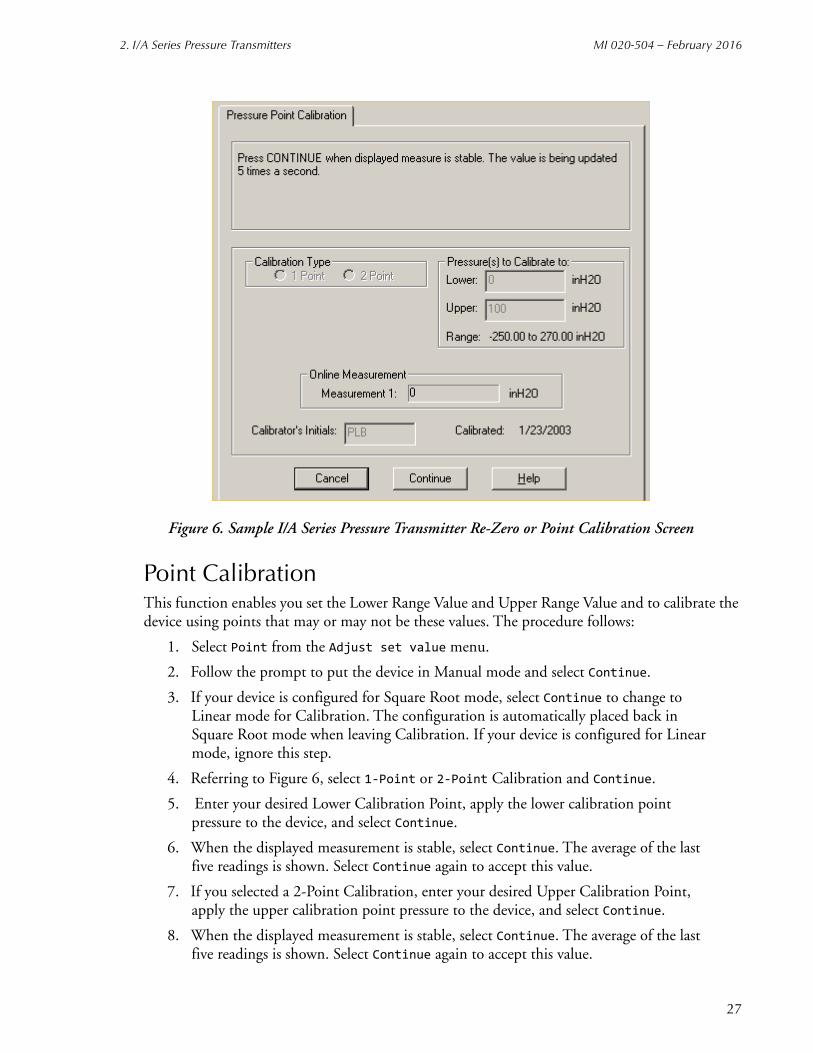
Figure 6. Sample I/A Series Pressure Transmitter Re-Zero or Point Calibration Screen
Point CalibrationThis function enables you set the Lower Range Value and Upper Range Value and to calibrate the device using points that may or may not be these values. The procedure follows:
1. Select Point from the Adjust set value menu.
2. Follow the prompt to put the device in Manual mode and select Continue.
3. If your device is configured for Square Root mode, select Continue to change to Linear mode for Calibration. The configuration is automatically placed back in Square Root mode when leaving Calibration. If your device is configured for Linear mode, ignore this step.
4. Referring to Figure 6, select 1-Point or 2-Point Calibration and Continue.
5. Enter your desired Lower Calibration Point, apply the lower calibration point pressure to the device, and select Continue.
6. When the displayed measurement is stable, select Continue. The average of the last five readings is shown. Select Continue again to accept this value.
7. If you selected a 2-Point Calibration, enter your desired Upper Calibration Point, apply the upper calibration point pressure to the device, and select Continue.
8. When the displayed measurement is stable, select Continue. The average of the last five readings is shown. Select Continue again to accept this value.
27

MI 020-504 – February 2016 2. I/A Series Pressure Transmitters
9. Enter the calibrator’s initials and select Continue. The current calibration date is automatically displayed.
10. Follow the prompt to put the device back into Automatic mode. Select Continue to resume dynamic measurements.
Re-RangeThis function enables you to rerange your device without applying calibration pressure. The procedure follows:
1. Select Re-Range from the Adjust set value menu.
2. Follow the prompt to put the device in Manual mode and select Continue.
3. Enter your desired Lower Range Value (LRV) and Upper Range Value (URV) in either units shown and select Continue.
4. Follow the prompt to put the device back into Automatic mode. Select Continue to resume dynamic measurements.
Figure 7. Sample I/A Series Pressure Transmitter Re-Range Screen
28

2. I/A Series Pressure Transmitters MI 020-504 – February 2016
Restore DefaultThis function enables you to restore all calibration parameters to their factory default settings.
1. Select Restore Default from the Adjust set value menu.
2. Follow the prompt to put the device in Manual mode and select Continue.
3. To reconfirm that you want to restore all calibration parameters to their default settings, select Continue.
4. Follow the prompt to put the device back into Automatic mode. Select Continue to resume dynamic measurements
mA CalibrationAs your device was accurately calibrated at the factory, this function is not normally required. This procedure should only be performed if the mA value displayed on the Device Data screen does not agree with the value measured by an accurate mA meter installed in the loop wiring.
NOTEBefore performing a mA Calibration, perform the Point Calibration procedure described on page 27. A mA calibration may no longer be necessary.
1. Insert an accurate mA meter (or digital voltmeter and precision resistor) in the loop wiring.
2. Select mA from the Adjust set value menu.
3. Follow the prompt to put the device in Manual mode and select Continue.
4. Select 4 mA Output.
Figure 8. Sample I/A Series Pressure Transmitter mA Calibration Screen
29

MI 020-504 – February 2016 2. I/A Series Pressure Transmitters
30
5. Set the Step Size from the menu (-0.5, -0.05, -0.005, 0.005, 0.05, 0.5) and select Apply.
6. Repeat Step 5 until you are satisfied with the output on the meter. The cumulative change is shown on the screen display.
7. Select 20 mA Output.
8. Repeat Steps 5 and 6. When finished, select Continue.
9. The screen then displays the adjustments. To accept this change and save the calibration to the transmitter, select Continue.
10. Follow the prompt to put the device back into Automatic mode. Select Continue to resume dynamic measurements.
Configuration
Identifier Tab Screen
Figure 9. Sample I/A Series Pressure Transmitter Identifier Tab Screen
Field Entry
Tag Number Enter maximum of 12 characters. The first 8 characters become the database filename.
Tag Name Enter maximum of 14 characters. Optional, used for reference only.
Device Name Enter maximum of 6 characters.NOTE: To disable enhanced protocol name checking with I/A Series Versions 3.0 or later, enter DevNam.
Location Enter maximum of 14 characters. Optional, used for reference only.

2. I/A Series Pressure Transmitters MI 020-504 – February 2016
Transmitter Parameter Configuration Tab Screen
Figure 10. Sample I/A Series Pressure Transmitter Parameter Configuration Tab Screen
Field Entry
Measurement #1
Square Root Mode = Square Root; Blank = Linear.
Units Select from menu of pressure units or select Custom to enter user-configured units.
Lower Range Value Enter value at which transmitter outputs 4 mA. Must be 0 if M1 or M2 is in Square Root mode.
Upper Range Value Enter value at which transmitter outputs 20 mA.
Upper Range Limit Shows value of Upper Range Limit of transmitter.
Measurement #2 Similar to Measurement #1.
Turn off Enable or Disable Measurement #2.
Sqroot Low Flow Mode Select Active or 10% of Flow Cut Off.
External Zero Select Enable or Disable.
Output Mode Select Digital or 4-20 mA.
mA Output Fail Safe Select Down Scale or Up Scale.
Output Damping Select one of nine choices from No Damping to 32 seconds.
Temperature Fail Strategy Select Fail or Continue.
31

MI 020-504 – February 2016 2. I/A Series Pressure Transmitters
32
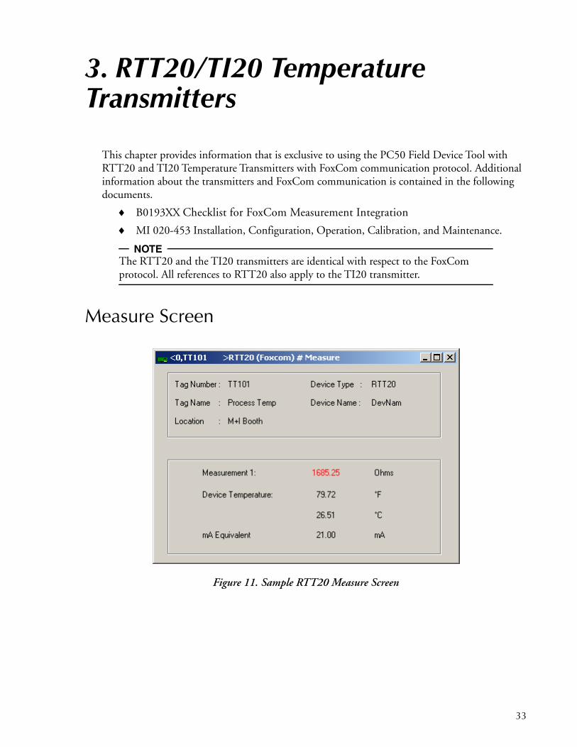
3. RTT20/TI20 Temperature Transmitters
This chapter provides information that is exclusive to using the PC50 Field Device Tool with RTT20 and TI20 Temperature Transmitters with FoxCom communication protocol. Additional information about the transmitters and FoxCom communication is contained in the following documents.
B0193XX Checklist for FoxCom Measurement Integration
MI 020-453 Installation, Configuration, Operation, Calibration, and Maintenance.
NOTEThe RTT20 and the TI20 transmitters are identical with respect to the FoxCom protocol. All references to RTT20 also apply to the TI20 transmitter.
Measure Screen
Figure 11. Sample RTT20 Measure Screen
33
MI 020-504 – February 2016 3. RTT20/TI20 Temperature Transmitters
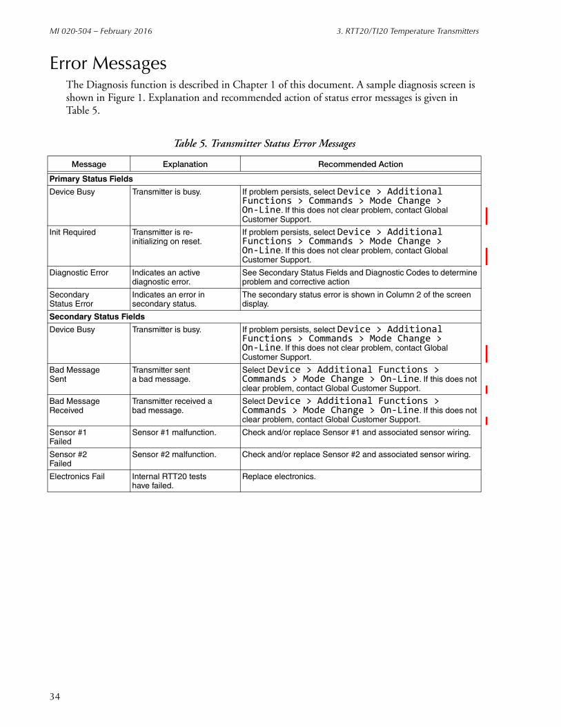
Error MessagesThe Diagnosis function is described in Chapter 1 of this document. A sample diagnosis screen is shown in Figure 1. Explanation and recommended action of status error messages is given in Table 5.
Table 5. Transmitter Status Error Messages
Message Explanation Recommended Action
Primary Status Fields
Device Busy Transmitter is busy. If problem persists, select Device > Additional Functions > Commands > Mode Change > On-Line. If this does not clear problem, contact Global Customer Support.
Init Required Transmitter is re-initializing on reset.
If problem persists, select Device > Additional Functions > Commands > Mode Change > On-Line. If this does not clear problem, contact Global Customer Support.
Diagnostic Error Indicates an activediagnostic error.
See Secondary Status Fields and Diagnostic Codes to determine problem and corrective action
Secondary Status Error
Indicates an error insecondary status.
The secondary status error is shown in Column 2 of the screen display.
Secondary Status Fields
Device Busy Transmitter is busy. If problem persists, select Device > Additional Functions > Commands > Mode Change > On-Line. If this does not clear problem, contact Global Customer Support.
Bad MessageSent
Transmitter senta bad message.
Select Device > Additional Functions > Commands > Mode Change > On-Line. If this does not clear problem, contact Global Customer Support.
Bad MessageReceived
Transmitter received abad message.
Select Device > Additional Functions > Commands > Mode Change > On-Line. If this does not clear problem, contact Global Customer Support.
Sensor #1Failed
Sensor #1 malfunction. Check and/or replace Sensor #1 and associated sensor wiring.
Sensor #2Failed
Sensor #2 malfunction. Check and/or replace Sensor #2 and associated sensor wiring.
Electronics Fail Internal RTT20 testshave failed.
Replace electronics.
34

3. RTT20/TI20 Temperature Transmitters MI 020-504 – February 2016
CalibrationYou can perform the following calibration procedures on an RTT20 Transmitter using the PC50 Field Device Tool:
N-Point Calibration
Custom Input Curve
ReRange
mA Calibration
Restore Factory
The calibration procedures are accessed as follows:
Device > Additional functions > Adjust set value
Except the path for Restore Factory is:
Device > Additional functions > Commands
N-Point CalibrationThis function enables you to perform a 1-, 2-, 3-, or 5-Point Calibration. The differences are explained below.
1-Point CalibrationThe RTT20 permits you to select any temperature within the configured range that is of particular interest to you. You are not required to use the LRV as the calibration point. The net effect is that a constant offset is utilized over the entire sensor curve. To view or change the value entered, see the note in “Custom Input Curve” on page 37.
2-Point CalibrationThe RTT20 permits you to select any two temperatures in the region of interest within the configured range of the transmitter. You are not required to use the LRV and URV as the calibration points. The temperatures must be increasing in value. The resulting offsets are then straightline calculated to the LRV and URV. Picture an offset line defining the correction to the standard, starting from the LRV, passing through the two calibration points, and continuing to the URV. To view or change any value entered, see the note in “Custom Input Curve” on page 37.
3- and 5- Point CalibrationThe RTT20 permits you to select any three (or five) temperatures in the region of interest within the configured range of the transmitter. The temperature must be increasing in value. The resulting offsets are then straightline calculated to the LRV and URV. Picture an offset line defining the correction to the standard, starting from the LRV, passing through the three (or five) calibration points, and continuing to the URV. To view or change any values entered, see note in “Custom Input Curve” on page 37.
35
MI 020-504 – February 2016 3. RTT20/TI20 Temperature Transmitters
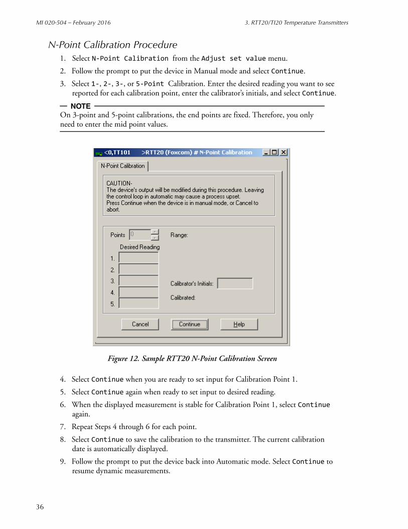
N-Point Calibration Procedure1. Select N-Point Calibration from the Adjust set value menu.
2. Follow the prompt to put the device in Manual mode and select Continue.
3. Select 1-, 2-, 3-, or 5-Point Calibration. Enter the desired reading you want to see reported for each calibration point, enter the calibrator’s initials, and select Continue.
NOTEOn 3-point and 5-point calibrations, the end points are fixed. Therefore, you only need to enter the mid point values.
Figure 12. Sample RTT20 N-Point Calibration Screen
4. Select Continue when you are ready to set input for Calibration Point 1.
5. Select Continue again when ready to set input to desired reading.
6. When the displayed measurement is stable for Calibration Point 1, select Continue again.
7. Repeat Steps 4 through 6 for each point.
8. Select Continue to save the calibration to the transmitter. The current calibration date is automatically displayed.
9. Follow the prompt to put the device back into Automatic mode. Select Continue to resume dynamic measurements.
36

3. RTT20/TI20 Temperature Transmitters MI 020-504 – February 2016
Custom Input CurveThe Custom Input Curve screen functions a little differently. If the Points field is 0, then the transmitter is using the factory installed calibration. If the number of points is 2 to 22, the transmitter uses the calibration data entered into the custom curve table.
NOTESince it is not possible to leave the input calibration values in memory when performing a Custom Input Curve calibration, it is strongly recommended that the transmitter database be stored to a file prior to making drastic changes in the calibration data.
The procedure to input a custom curve is as follows:
1. Select Custom Input Curve from Adjust set value menu.
2. Follow the prompt to put the device in Manual mode and select Continue.
3. Select the number of points you want in your custom curve (2 - 22).
Figure 13. Sample RTT20 Custom Input Curve Screen
37

MI 020-504 – February 2016 3. RTT20/TI20 Temperature Transmitters
! CAUTIONIf all the Measured/Desired fields are “0”, then the number of points must be “0” prior to exiting the Custom Input Curve screen. If the number of points is not zero (2-22) and no measured/desired data is entered into the fields on the Custom Input Curve screen, the transmitter drives its output to whatever “0” means for that sensor. The transmitter does not respond to any change in input in this condition.
NOTEThe calibration data from any of the above calibration options is stored in the custom curve memory locations. Therefore, if you wish to view or change a specific data point, you can enter the custom curve selection and view, edit, or clear all values.
4. In the Measured column, enter the values the RTT20 displays now; in the Desired column, enter the values you want displayed. For example, if a Measured value was 100.00 but you wanted 100.25, enter 100.00 as the Measured number and 100.25 as the Desired number.
5. Enter the calibrator’s initials and select Continue. The current calibration date is automatically displayed.
6. Select Continue to save the custom curve to the RTT20 transmitter.
7. Follow the prompt to put the device back into Automatic mode. Press Continue to resume dynamic measurements.
38

3. RTT20/TI20 Temperature Transmitters MI 020-504 – February 2016
ReRangeThis function enables you to rerange your device without applying inputs representing temperatures. The procedure to do this is as follows:
1. Select ReRange from the Adjust set value menu.
2. Follow the prompt to put the device in Manual mode and select Continue.
3. Enter your desired Lower Range Value (LRV) and Upper Range Value (URV) and select Continue.
Figure 14. Sample RTT20 ReRange Screen
4. Select Continue to save the new custom curve to the RTT20 transmitter.
5. Follow the prompt to put the device back into Automatic mode. Select Continue to resume dynamic measurements.
Restore FactoryThis function restores the mA calibration factory settings. The procedure to do this is as follows:
1. Select Restore Factory from the Commands menu.
2. Follow the prompt to put the device in Manual mode and select Continue.
3. To reconfirm that you want to restore the mA calibration factory settings, select Continue. The Factory Calibration is restored and the calibration date automatically changes.
39

MI 020-504 – February 2016 3. RTT20/TI20 Temperature Transmitters
Figure 15. Sample RTT20 Restore Factory Calibration Screen
4. Enter the calibrator’s initials and select Continue.
5. Follow the prompt to put the transmitter back into Automatic mode. Select Continue to resume dynamic measurements.
mA CalibrationAs your device was accurately calibrated at the factory, this function is not normally required. This procedure should only be performed if the mA value displayed on the Measure screen does not agree with the value measured by an accurate mA meter installed in the loop wiring.
NOTEBefore performing a mA Calibration, perform the N-Point Calibration procedure described on page 35. A mA calibration may no longer be necessary.
The procedure to perform a mA Calibration is as follows:
1. Insert an accurate mA meter (or digital voltmeter and precision resistor) in the loop wiring.
2. Select mA Calibration from the Adjust set value menu.
3. Follow the prompt to put the device in Manual mode and select Continue.
4. Select 4 mA Output.
40

3. RTT20/TI20 Temperature Transmitters MI 020-504 – February 2016
Figure 16. Sample RTT20 mA Calibration Screen (FoxCom Device)
5. Set Step Size from menu (-0.5, -0.05, -0.005, 0.005, 0.05, 0.5), and select Apply.
6. Repeat Step 4 until you are satisfied with the output. The cumulative change is shown on the screen.
7. Select 20 mA Output.
8. Repeat Steps 4 and 5. When finished, select Continue.
9. The screen then displays the adjustments. To accept this change, select Continue.
10. Follow the prompt to put the device back into Automatic mode. Select Continue to resume dynamic measurements.
41
MI 020-504 – February 2016 3. RTT20/TI20 Temperature Transmitters
Configuration
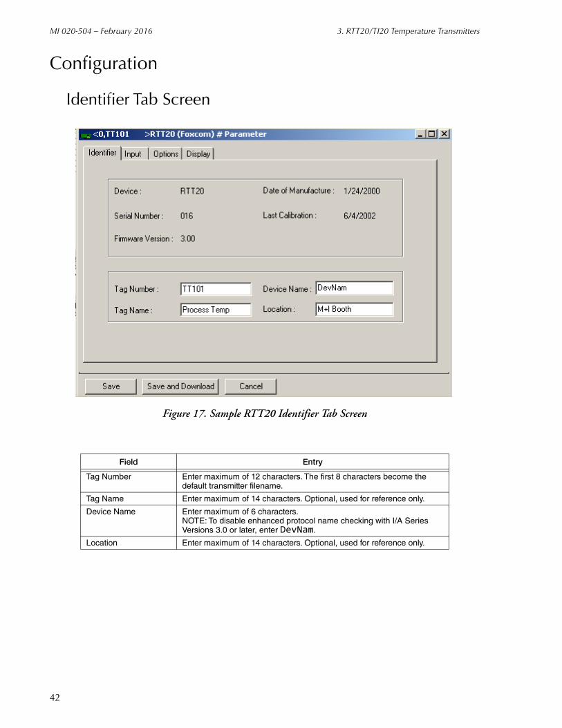
Identifier Tab Screen
Figure 17. Sample RTT20 Identifier Tab Screen
Field Entry
Tag Number Enter maximum of 12 characters. The first 8 characters become the default transmitter filename.
Tag Name Enter maximum of 14 characters. Optional, used for reference only.
Device Name Enter maximum of 6 characters.NOTE: To disable enhanced protocol name checking with I/A Series Versions 3.0 or later, enter DevNam.
Location Enter maximum of 14 characters. Optional, used for reference only.
42

3. RTT20/TI20 Temperature Transmitters MI 020-504 – February 2016
Input Tab Screen
Figure 18. Sample RTT20 Input Tab Screen
Field Entry
Sensor Type Select RTD Sensor, ThermoCouple, or Special Input.
Input Config. Select from menu of input types.
Wire Type For RTDs, select from menu of wire types.
Linearization Select Normal or Dewpoint.
2-Wire Dual Calculation For 2-Wire Dual RTD, select Redundant, Average, or Difference.
Measurement
Lower Range Limit Shows value of Lower Range Limit of transmitter.
Upper Range Limit Shows value of Upper Range Limit of transmitter.
Lower Range Value Enter value at which transmitter outputs 4 mA.
Upper Range Value Enter value at which transmitter outputs 20 mA.
Measurement Units Select from menu of units.
Secondary Measurement Units Select from menu of units.
Cold Junction
Cold Junction Configuration For thermocouples, select Internal Sensor, External Sensor, Fixed Value, or Disabled.
43

MI 020-504 – February 2016 3. RTT20/TI20 Temperature Transmitters
Options Tab Screen
Figure 19. Sample RTT20 Options Tab Screen
Field Entry
Output Mode Select Analog (4 - 20 mA) or Digital.
Fault Detection On = On; Blank = Off.
Analog Output Failsafe
Failsafe On = Failsafe On; Blank = Failsafe Off.
Range If Failsafe is On, select 3.6-3.8 (Downscale) or 20.75-23.0 (Upscale).
Value Enter value within range selected.
Damping Select one of nine choices from No Damping to 32 seconds.
Sensor Validation Enter value between 0.25 and 10 seconds.
Intelligent Smoothing Enter value between 0 and 30 seconds.
Power Supply
Frequency Select 50 or 60 Hz.
Filter Select Standard or High Speed.
44

3. RTT20/TI20 Temperature Transmitters MI 020-504 – February 2016
Display Tab Screen
Figure 20. Sample RTT20 Display Tab Screen
Field Entry
Type of Display Installed Shows None, One Line or Three Line indicator installed.
Pushbutton Enable = Enabled; Blank = Disabled.
Language Select English, French, German, or Spanish.
Top Line Display Select from menu (EGU, Percent of Range, mA, EGU and Percent, or EGU and mA).
Bottom Line Label If three-line display, enter maximum of seven characters.
45

MI 020-504 – February 2016 3. RTT20/TI20 Temperature Transmitters
46

4. IMT25 and IMT25L Magnetic Flow Transmitters
This chapter provides information that is exclusive to using the PC50 Field Device Tool with IMT25 Magnetic Flow Transmitters with FoxCom communication protocol. Additional information about these transmitters and FoxCom communication is contained in the following documents.
B0193XXChecklist for FoxCom Measurement Integration
MI 021-390Operation, Calibration, and Configuration
Measure Screen
Figure 21. Sample IMT25 Measure Screen
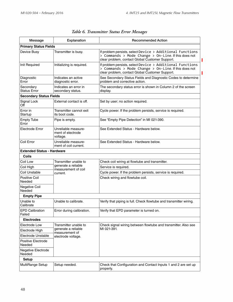
Error MessagesThe Diagnosis function is described in Chapter 1 of this document. A sample diagnosis screen is shown in Figure 1. Explanation and recommended action of status error messages is given in Table 6.
47
MI 020-504 – February 2016 4. IMT25 and IMT25L Magnetic Flow Transmitters
Table 6. Transmitter Status Error Messages
Message Explanation Recommended Action
Primary Status Fields
Device Busy Transmitter is busy. If problem persists, select Device > Additional Functions > Commands > Mode Change > On-Line. If this does not clear problem, contact Global Customer Support.
Init Required Initializing is required. If problem persists, select Device > Additional Functions > Commands > Mode Change > On-Line. If this does not clear problem, contact Global Customer Support.
DiagnosticError
Indicates an activediagnostic error.
See Secondary Status Fields and Diagnostic Codes to determine problem and corrective action.
Secondary Status Error
Indicates an error insecondary status.
The secondary status error is shown in Column 2 of the screen display.
Secondary Status Fields
Signal LockOff
External contact is off. Set by user; no action required.
Error in Startup
Transmitter cannot exitits boot code.
Cycle power. If the problem persists, service is required.
Empty TubeError
Pipe is empty. See “Empty Pipe Detection” in MI 021-390.
Electrode Error Unreliable measure-ment of electrodevoltage.
See Extended Status - Hardware below.
Coil Error Unreliable measure-ment of coil current.
See Extended Status - Hardware below.
Extended Status - Hardware
Coils
Coil Low Transmitter unable togenerate a reliablemeasurement of coilcurrent.
Check coil wiring at flowtube and transmitter.
Coil High Service is required.
Coil Unstable Cycle power. If the problem persists, service is required.
Positive CoilNeeded
Check wiring and flowtube coil.
Negative CoilNeeded
Empty Pipe
Unable to Calibrate
Unable to calibrate. Verify that piping is full. Check flowtube and transmitter wiring.
EPD Calibration Failed
Error during calibration. Verify that EPD parameter is turned on.
Electrodes
Electrode Low Transmitter unable togenerate a reliablemeasurement ofelectrode voltage.
Check signal wiring between flowtube and transmitter. Also see MI 021-391.Electrode High
Electrode Unstable
Positive Electrode Needed
Negative Electrode Needed
Setup
MultiRange Setup Setup needed. Check that Configuration and Contact Inputs 1 and 2 are set up properly.
48

4. IMT25 and IMT25L Magnetic Flow Transmitters MI 020-504 – February 2016
CalibrationYou can perform the following calibration procedures on an IMT25 transmitter using the PC50 Field Device Tool:
mA Output
Reset Totals
Empty Pipe.
The calibration procedures are accessed as follows:
Device > Additional functions > Adjust set value
Empty PipeThe empty pipe detector can be used to force the transmitter outputs to stay at zero when the flowtube is empty. The empty pipe circuit must be calibrated to the fluid in the flowtube. The flowtube must be full of process fluid (flowing or still) to use this calibration procedure. The calibration procedure leaves the empty pipe detector in the ON condition. The detector can be turned off in the Configuration menu.
1. Select Empty Pipe from the Adjust set value menu.
2. Follow the prompt to put the device in Manual mode and select Continue.
Extended Status - Process
Process Problems
Signal Lock Signal lock is on. Check that Contact Inputs 1 and 2 are activated by an external set of contacts or switch.
Pulses Lag Total Totalizer putting outpulses at the maximumrate but falling behindthe actual total.
Reconfigure totalizer display so that each pulse represents a larger volume.
Total Rollover Total exceeds limit ofconfigured format.
Reconfigure total format if necessary and reset totals.
A to D Calibration Failed
Electronics problem. Service is required.
Alarms
High Flow Flow above configuredhigh flow rate.
Make process change or reconfigure alarm setpoint.
Low Flow Flow below configured low flow rate.
High Forward Total 1 Total above configured High Fwd Tot 1.
Make process change or reconfigure Tot Alm Setpt and reset totals.
High Forward Total 2 Total above configured High Fwd Tot 2.
Empty Pipe Transmitter thinkspipe is insufficientlyfull to make measurements.
Make process change or, if not empty, check wiring and recalibrate.
Table 6. Transmitter Status Error Messages (Continued)
Message Explanation Recommended Action
49

MI 020-504 – February 2016 4. IMT25 and IMT25L Magnetic Flow Transmitters
3. Fill the flowtube and then select Continue to start the Empty Pipe Calibration process.
4. Wait while the device is calibrating.
5. Follow the prompt to put the device back into Automatic mode. Select Continue to resume dynamic measurements.
mA OutputAs your device was accurately calibrated at the factory, this function is not normally required. However, the mA output can be trimmed with this procedure if it is necessary to match the output to the output of a specific receiving device.
The procedure to perform a mA Output Calibration on a FoxCom device is:
1. Insert an accurate mA meter (or digital voltmeter and precision resistor) in the loop wiring.
2. Select mA Output from the Adjust set value menu.
3. Follow the prompt to put the device in Manual mode and select Continue.
4. Select 4 mA Output.
5. Set the Step Size (-0.5, -0.05, -0.005, 0.005, 0.05, 0.5), and select Apply.
6. Repeat Step 4 until you are satisfied with the output. The cumulative change is shown on the screen display.
7. Select 20 mA Output.
8. Repeat Steps 4 and 5. When finished, select Continue.
9. The screen then displays the adjustments. To accept this change, select Continue.
10. Follow the prompt to put the device back into Automatic mode. Select Continue to resume dynamic measurement.
Figure 22. Sample IMT25 mA Calibration Screen
50

4. IMT25 and IMT25L Magnetic Flow Transmitters MI 020-504 – February 2016
Reset TotalsThis procedure resets the transmitter totals. The Net, Forward and Reverse Totals are reset as a group. The Grand Total is individually reset.
1. Select Reset Totals from the Adjust set value menu.
2. Follow the prompt to put the device in Manual mode and select Continue.
3. Select the device total(s) to reset to zero. You can select Net, Forward, and Reverse Totals or Grand Total. Then select Continue.
Figure 23. Sample IMT25 Reset Totals Screen
4. Follow the prompt to put the device back into Automatic mode. Select Continue to resume dynamic measurements.
ConfigurationNOTE
For IMT25L devices, some configuration parameters do not apply.
51

MI 020-504 – February 2016 4. IMT25 and IMT25L Magnetic Flow Transmitters
Identifier Tab Screen
Figure 24. Sample IMT25 Identifier Tab Screen
Field Entry
Tag Number Enter maximum of 12 characters. The first 8 characters become the transmitter filename.
Tag Name Enter maximum of 14 characters. Optional, used for reference only.
Device Name Enter maximum of 6 characters.NOTE: To disable enhanced protocol name checking with I/A Series Versions 3.0 or later, enter DevNam.
Location Enter maximum of 14 characters. Optional, used for reference only.
52
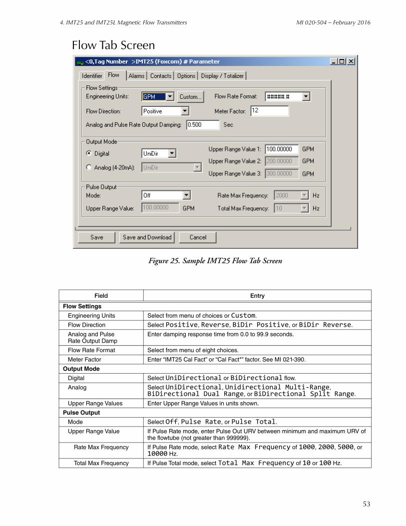
4. IMT25 and IMT25L Magnetic Flow Transmitters MI 020-504 – February 2016
Flow Tab Screen
Figure 25. Sample IMT25 Flow Tab Screen
Field Entry
Flow Settings
Engineering Units Select from menu of choices or Custom.
Flow Direction Select Positive, Reverse, BiDir Positive, or BiDir Reverse.
Analog and PulseRate Output Damp
Enter damping response time from 0.0 to 99.9 seconds.
Flow Rate Format Select from menu of eight choices.
Meter Factor Enter “IMT25 Cal Fact” or “Cal Fact*” factor. See MI 021-390.
Output Mode
Digital Select UniDirectional or BiDirectional flow.
Analog Select UniDirectional, Unidirectional Multi-Range, BiDirectional Dual Range, or BiDirectional Split Range.
Upper Range Values Enter Upper Range Values in units shown.
Pulse Output
Mode Select Off, Pulse Rate, or Pulse Total.
Upper Range Value If Pulse Rate mode, enter Pulse Out URV between minimum and maximum URV of the flowtube (not greater than 999999).
Rate Max Frequency If Pulse Rate mode, select Rate Max Frequency of 1000, 2000, 5000, or 10000 Hz.
Total Max Frequency If Pulse Total mode, select Total Max Frequency of 10 or 100 Hz.
53

MI 020-504 – February 2016 4. IMT25 and IMT25L Magnetic Flow Transmitters
Alarms Tab Screen
Figure 26. Sample IMT25 Alarms Tab Screen
Field Entry
For All Alarms
Alarming Enabled = On; Blank = Off.
Clear Alarms Automatically = Auto; Blank = Manual.
Blink On Alarm = Blink; Blank = Don’t Blink.
Rate Output Response Select No effect, Go Downscale, or Go Upscale.
Alarm Display Definition
High Flow Rate = On; Blank = Off. If On, enter Set Point and Deadband.
Low Flow Rate = On; Blank = Off. If On, enter Set Point and Deadband.
High Forward Total 1 = On; Blank = Off. If On, enter Set Point.
High Forward Total 2 = On; Blank = Off. If On, enter Set Point.
Empty Pipe = On; Blank = Off.
Turn On All Turns all alarms on.
Turn Off All Turns all alarms off.
54

4. IMT25 and IMT25L Magnetic Flow Transmitters MI 020-504 – February 2016
Contacts Tab Screen
Figure 27. Sample IMT25 Contacts Tab Screen
Field Entry
Contacts
Contact 1 Function Select Off, Ack Alarm, Reset Net Total, Reset Gr Total, Reset All Total, Multi-range, or Signal Lock.
Contact 1 Operation If Contact 1 Function is not Off, select Normally Open or Normally Closed.
Contact 2 Function Similar to Contact 1 Function.
Contact 2 Operation Similar to Contact 1 Operation.
Relay 1
Relay Function Select Off, Alarm, Alarm & Diag, Diagnostics, Flow Direction, or Test Mode.
Relay Alarm If Relay Function is not Off, select High Rate, Low Rate, High Forward Total 1, High Forward Total 2, Empty Pipe, or Any Alarm.
Relay Operation If Relay Function is not Off, select Normally Open or Normally Closed.
Suppress Relay If Relay Function is not Off, select Yes to suppress reactivation of an alarm or No for no suppression.
Relay 2 (Similar to Relay 1)
55

MI 020-504 – February 2016 4. IMT25 and IMT25L Magnetic Flow Transmitters
Options Tab Screen
Figure 28. Sample IMT25 Options Tab Screen
Field Entry
Tube Identification
Model Code Enter model code of flowtube.
Serial Number Enter serial number of flowtube.
Diagnostics
Rate Response Diagnostics Select Go Downscale or Go Upscale.
Blink On Diagnostic Error = Blink; Blank = Don’t Blink.
Functional Security at the IMT25 Keypad (not applicable to HART device)
Enable Passcode 1 = Enable; Blank = Disable. If enabled, select Setup, Totals Reset, Setup & Totals, Test Mode, Test Mode & Setup, Test Mode and Totals, or Test Mode, Setup & Totals. Then enter 4 digit passcode.
Enable Passcode 2 Similar to Enable Passcode 1.
Noise Reduction = On; Blank = Off.
Empty Pipe Detection = On; Blank = Off.
Line Frequency Select 50 Hz or 60 Hz.
Empty Pipe Effect Select No Effect or Auto Signal Lock.
56
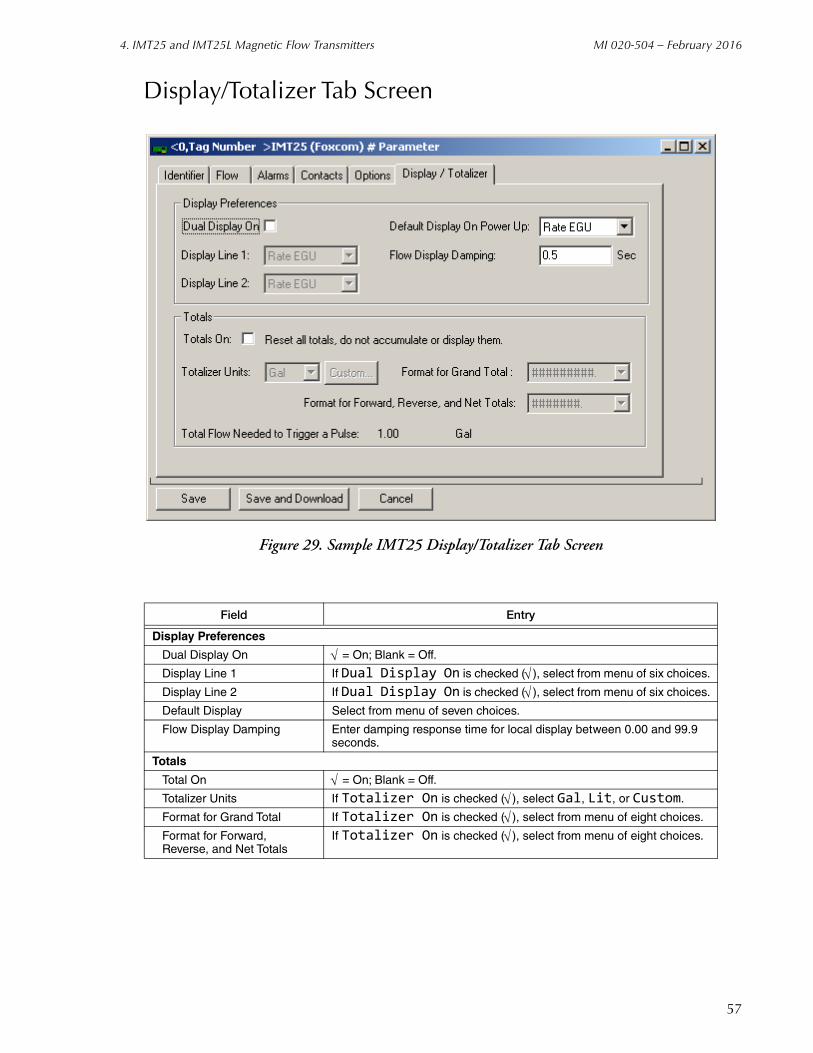
4. IMT25 and IMT25L Magnetic Flow Transmitters MI 020-504 – February 2016
Display/Totalizer Tab Screen
Figure 29. Sample IMT25 Display/Totalizer Tab Screen
Field Entry
Display Preferences
Dual Display On = On; Blank = Off.
Display Line 1 If Dual Display On is checked ( ), select from menu of six choices.
Display Line 2 If Dual Display On is checked ( ), select from menu of six choices.
Default Display Select from menu of seven choices.
Flow Display Damping Enter damping response time for local display between 0.00 and 99.9 seconds.
Totals
Total On = On; Blank = Off.
Totalizer Units If Totalizer On is checked ( ), select Gal, Lit, or Custom.
Format for Grand Total If Totalizer On is checked ( ), select from menu of eight choices.
Format for Forward,Reverse, and Net Totals
If Totalizer On is checked ( ), select from menu of eight choices.
57

MI 020-504 – February 2016 4. IMT25 and IMT25L Magnetic Flow Transmitters
58

5. IMT96 Magnetic Flow Transmitters
This chapter provides information that is exclusive to using the PC50 Field Device Tool with IMT96 Magnetic Flow Transmitters with FoxCom communication protocol. Additional information about these transmitters and FoxCom communication is contained in the following documents.
B0193XXChecklist for FoxCom Measurement Integration
MI 021-403Operation, Calibration, and Configuration.
Measure Screen
Figure 30. Sample IMT96 Measure Screen
59

MI 020-504 – February 2016 5. IMT96 Magnetic Flow Transmitters
Error MessagesThe Diagnosis function is described in Chapter 1 of this document. A sample diagnosis screen is shown in Figure 1. Explanation and recommended action of status error messages is given in Table 7.
Table 7. Transmitter Status Error Messages
Message Explanation Recommended Action
Primary Status Fields
Device Busy Transmitter is busy. If problem persists, select Device > Additional Functions > Commands > Mode Change > On-Line. If this does not clear problem, contact Global Customer Support.
Init Required Initializing is required. If problem persists, select Device > Additional Functions > Commands > Mode Change > On-Line. If this does not clear problem, contact Global Customer Support.
DiagnosticError
Indicates an activediagnostic error.
See Secondary Status Fields and Diagnostic Codes to determine problem and corrective action.
Secondary Status Error
Indicates an error insecondary status.
The secondary status error is shown in Column 2 of the screen display.
Secondary Status Fields
Signal LockOff
External contact is off. Set by user; no action required.
Startup Test Transmitter cannotexit its boot code.
Cycle power. If the problem persists, service is required.
Electrode Test Unreliable measure-ment of electrodevoltage.
See Extended Status - Hardware below.
Coil Test Unreliable measure-ment of coil current.
See Extended Status - Hardware below.
Extended Status - Hardware
Coils
Low CoilCurrent Test
Transmitter unable togenerate a reliablemeasurement of coilcurrent.
Check coil wiring at flowtube and transmitter.
High CoilCurrent Test
Service is required.
Positive Coil Test
Check wiring and flowtube coil.
Negative CoilTest
Electrodes
Electrode inRange Test
Transmitter unable togenerate a reliablemeasurement ofelectrode voltage.
Check signal wiring between flowtube and transmitter. Also see MI 020-391.
PositiveElectrode Test
NegativeElectrode Test
Setup
MultiRangeSetup
Setup needed. Check that Configuration and Contact Inputs 1 and 2 are set up properly.
Extended Status - Process
Process Problems
Signal LockTest
Signal lock is on. Check that Contact Inputs 1 and 2 are activated by an external set of contacts or switch.
60

5. IMT96 Magnetic Flow Transmitters MI 020-504 – February 2016
CalibrationYou can perform the following calibration procedures on an IMT96 transmitter using the PC50 Field Device Tool:
Zero Flow Calibration
Restore Zero Flow Default.
Reset Totals
mA Output
The calibration procedures are accessed as follows:
Device > Additional functions > Adjust set value
Zero Flow CalibrationThis procedure causes the device to rezero the measurement when zero flow is in the flowtube.
1. Select Zero Flow Calibration from the Adjust set value menu or the Zero Flow icon from the device toolbar.
2. Follow the prompt to put the device in Manual mode and select Continue.
3. Select Continue when zero flow is present in the flowtube.
4. Wait while the device is zeroing.
5. Follow the prompt to put the device back into Automatic mode. Select Continue to resume dynamic measurements.
Pulses LagTotal Test
Totalizer putting outpulses at the maximumrate but falling behindthe actual total.
Reconfigure totalizer display so that each pulse represents a larger volume.
Total RolloverTest
Total exceeds limit ofconfigured format.
Reconfigure total format if necessary and reset totals.
A to D Calibration Test
Electronics problem. Service is required.
Alarms
High Flow Flow above configuredhigh flow rate.
Make process change or reconfigure alarm setpoint.
Low Flow Flow below configured low flow rate.
High ForwardTotal 1
Total above configured High Fwd Tot 1.
Make process change or reconfigure Tot Alm Setpt and reset totals.
High ForwardTotal 2
Total above configured High Fwd Tot 2.
Table 7. Transmitter Status Error Messages (Continued)
Message Explanation Recommended Action
61

MI 020-504 – February 2016 5. IMT96 Magnetic Flow Transmitters
Restore Zero Flow DefaultThis procedure restores the factory zero setting.
1. Select Restore Zero Flow Default from the Adjust set value menu.
2. Follow the prompt to put the device in Manual mode and select Continue.
3. Wait while the factory zero setting is restored.
4. Follow the prompt to put the device back into Automatic mode. Select Continue to resume dynamic measurements.
62
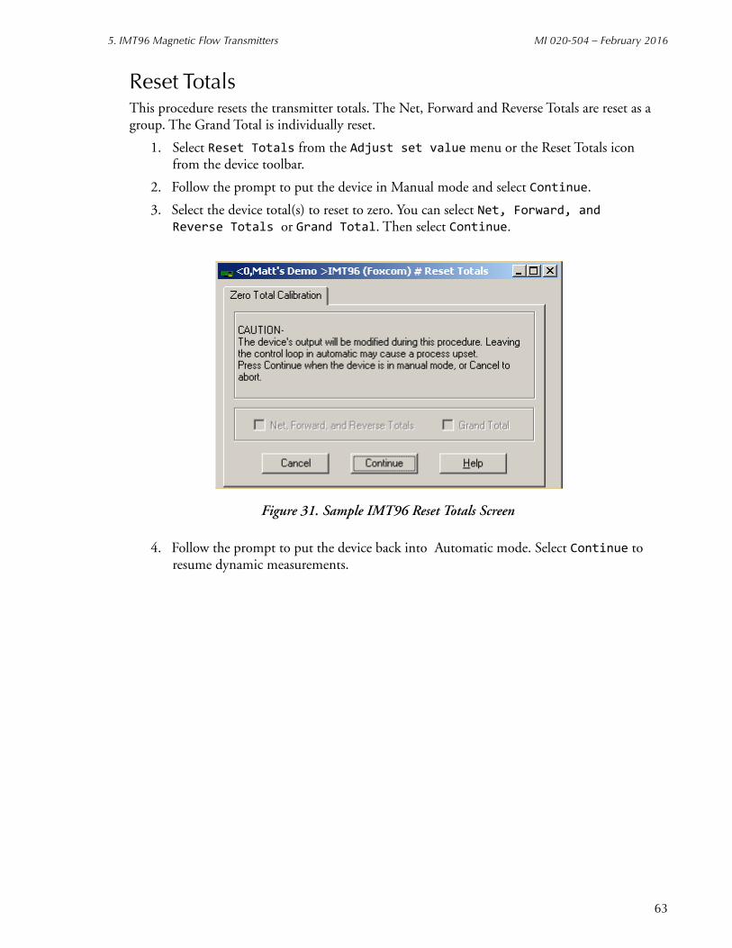
5. IMT96 Magnetic Flow Transmitters MI 020-504 – February 2016
Reset TotalsThis procedure resets the transmitter totals. The Net, Forward and Reverse Totals are reset as a group. The Grand Total is individually reset.
1. Select Reset Totals from the Adjust set value menu or the Reset Totals icon from the device toolbar.
2. Follow the prompt to put the device in Manual mode and select Continue.
3. Select the device total(s) to reset to zero. You can select Net, Forward, and Reverse Totals or Grand Total. Then select Continue.
Figure 31. Sample IMT96 Reset Totals Screen
4. Follow the prompt to put the device back into Automatic mode. Select Continue to resume dynamic measurements.
63

MI 020-504 – February 2016 5. IMT96 Magnetic Flow Transmitters
mA OutputAs your device was accurately calibrated at the factory, this function is not normally required. However, the mA output can be trimmed with this procedure if it is necessary to match the output to the output of a specific receiving device.
The procedure to perform a mA Output Calibration is:
1. Insert an accurate mA meter (or digital voltmeter and precision resistor) in the loop wiring.
2. Select mA Output from the Adjust set value menu.
3. Follow the prompt to put the device in Manual mode and select Continue.
4. Select 4 mA Output.
5. Set the Step Size (-0.5, -0.05, -0.005, 0.005, 0.05, 0.5), and select Apply.
6. Repeat Step 4 until you are satisfied with the output. The cumulative change is shown on the screen display.
7. Select 20 mA Output.
8. Repeat Steps 4 and 5. When finished, select Continue.
9. The screen then displays the adjustments. To accept this change, select Continue.
10. Follow the prompt to put the device back into Automatic mode. Select Continue to resume dynamic measurement.
Figure 32. Sample IMT96 mA Calibration Screen
64
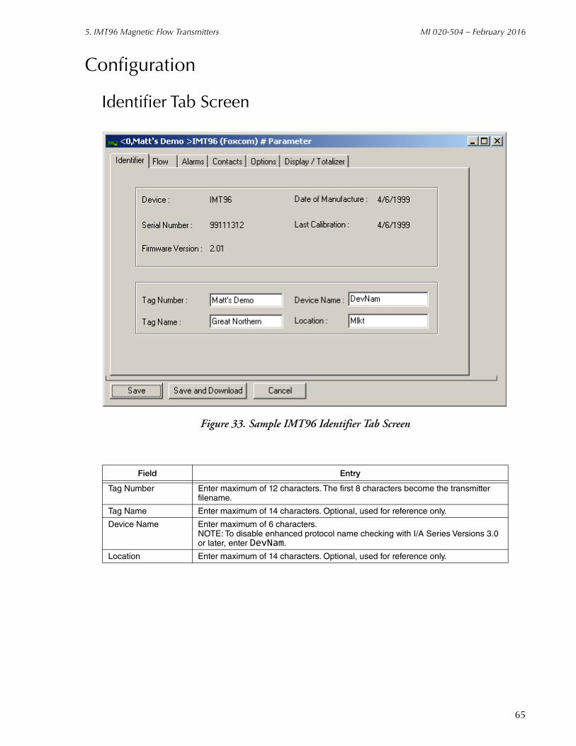
5. IMT96 Magnetic Flow Transmitters MI 020-504 – February 2016
Configuration
Identifier Tab Screen
Figure 33. Sample IMT96 Identifier Tab Screen
Field Entry
Tag Number Enter maximum of 12 characters. The first 8 characters become the transmitter filename.
Tag Name Enter maximum of 14 characters. Optional, used for reference only.
Device Name Enter maximum of 6 characters.NOTE: To disable enhanced protocol name checking with I/A Series Versions 3.0 or later, enter DevNam.
Location Enter maximum of 14 characters. Optional, used for reference only.
65

MI 020-504 – February 2016 5. IMT96 Magnetic Flow Transmitters
Flow Tab Screen
Figure 34. Sample IMT96 Flow Tab Screen
Field Entry
Flow SettingsEngineering Units Select from menu of choices or Custom.Flow Direction Select Positive, Reverse, BiDir Positive, or BiDir Reverse.Analog and PulseRate Output Damp.
Enter damping response time from 0.0 to 99.9 seconds.
Flow Rate Format Select from menu of eight choices.Meter Factor Enter the “IMT96 Cal Fact” factor or see MI 021-412.
Output ModeDigital Select UniDirectional or BiDirectional flow.Analog Select UniDirectional, Unidirectional Multi-Range,
BiDirectional Dual Range, or BiDirectional Split Range.Upper Range Values Enter Upper Range Values in units shown.
Pulse OutputMode Select Off, Pulse Rate, or Pulse Total.Upper Range Value If Pulse Rate Mode, enter Pulse Out URV between minimum and maximum URV
of the flowtube (not greater than 999999).Rate Max Frequency If Pulse Rate Mode, select Rate Max Frequency of 1000, 2000, 5000, or
10000 Hz.Total Max Frequency If Pulse Total Mode, select Total Max Frequency of 10 or 100 Hz.
66
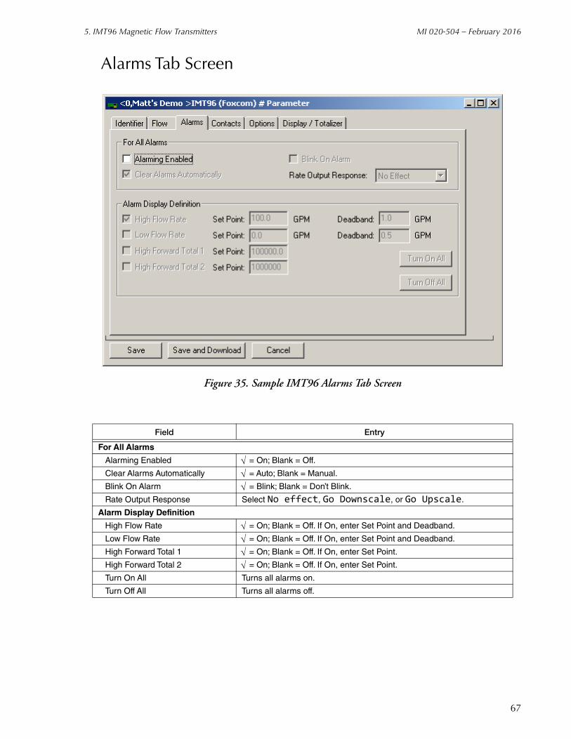
5. IMT96 Magnetic Flow Transmitters MI 020-504 – February 2016
Alarms Tab Screen
Figure 35. Sample IMT96 Alarms Tab Screen
Field Entry
For All Alarms
Alarming Enabled = On; Blank = Off.
Clear Alarms Automatically = Auto; Blank = Manual.
Blink On Alarm = Blink; Blank = Don’t Blink.
Rate Output Response Select No effect, Go Downscale, or Go Upscale.
Alarm Display Definition
High Flow Rate = On; Blank = Off. If On, enter Set Point and Deadband.
Low Flow Rate = On; Blank = Off. If On, enter Set Point and Deadband.
High Forward Total 1 = On; Blank = Off. If On, enter Set Point.
High Forward Total 2 = On; Blank = Off. If On, enter Set Point.
Turn On All Turns all alarms on.
Turn Off All Turns all alarms off.
67

MI 020-504 – February 2016 5. IMT96 Magnetic Flow Transmitters
Contacts Tab Screen
Figure 36. Sample IMT96 Contacts Tab Screen
Field Entry
Contacts
Contact 1 Function Select Off, Ack Alarm, Reset Net Total, Reset Gr Total, Reset All Total, Multi-range, or Signal Lock.
Contact 1 Operation If Contact 1 Function is not off, select Normally Open or Normally Closed.
Contact 2 Function Similar to Contact 1 Function.
Contact 2 Operation Similar to Contact 1 Operation
Relay 1
Relay Function Select Off, Alarm, Alarm & Diag, Diagnostics, Flow Direction, or Test Mode.
Relay Alarm If Relay Function is not off, select High Rate, Low Rate, High Forward Total 1, High Forward Total 2, or Any Alarm.
Relay Operation If Relay Function is not off, select Normally Open or Normally Closed.
Suppress Relay If Relay Function is not off, select Yes to suppress reactivation of an alarm or No for no suppression.
Relay 2 (Similar to Relay 1)
68

5. IMT96 Magnetic Flow Transmitters MI 020-504 – February 2016
Options Tab Screen
Figure 37. Sample IMT96 Options Tab Screen
Field Entry
Tube Identification
Model Code Enter model code of flowtube.
Serial Number Enter serial number of flowtube.
Diagnostics
Rate Response Diagnostics Select Go Downscale or Go Upscale.
Blink On Diagnostic Error = Blink; Blank = Don’t Blink.
Functional Security at the IMT96 Keypad
Enable Passcode 1 = Enable; Blank = Disable. If Enabled, select Setup, Totals Reset, Setup & Totals, Test Mode, Test Mode & Setup, Test Mode and Totals, or Test Mode, Setup & Totals. Then enter 4 digit passcode.
Enable Passcode 2 Similar to Enable Passcode 1.
Noise Reduction = On; Blank = Off.
Line Frequency Select 50 Hz or 60 Hz.
69

MI 020-504 – February 2016 5. IMT96 Magnetic Flow Transmitters
Display/Totalizer Tab Screen
Figure 38. Sample IMT96 Display/Totalizer Tab Screen
Field Entry
Display PreferencesDual Display On = On; Blank = Off.
Display Line 1 If Dual Display On is checked ( ), select from menu of six choices.Display Line 2 If Dual Display On is checked ( ), select from menu of six choices.
Default Display Select from menu of seven choices.
Flow Display Damping Enter damping response time for local display between 0.00 and 99.9 seconds.
TotalsTotal On = On; Blank = Off.Totalizer Units If Totalizer On is checked ( ), select Gal, Lit, or Custom.
Format for Grand Total If Totalizer On is checked ( ), select from menu of eight choices.
Format for Forward,Reverse, and Net Totals
If Totalizer On is checked ( ), select from menu of eight choices.
70

6. 83 Series Vortex Flowmeters
This chapter provides information that is exclusive to using the PC50 Field Device Tool with 83 Series Vortex Flowmeters with FoxCom communication protocol. Additional information about these transmitters and FoxCom communication is contained in the following documents.
B0193XXChecklist for FoxCom Measurement Integration
MI 019-19483F and 83W Installation, Configuration, Troubleshootingand Maintenance.
MI 019-19583S Installation, Configuration, Troubleshootingand Maintenance.
Measure Screen
Figure 39. Sample Vortex Measure Screen
71

MI 020-504 – February 2016 6. 83 Series Vortex Flowmeters
Error MessagesThe Diagnosis function is described in Chapter 1 of this document. A sample diagnosis screen is shown in Figure 1. Explanation and recommended action of status error messages is given in Table 8 and of diagnostic error messages in Table 9.
Status Error Messages
Table 8. Status Error Messages
Message Explanation Recommended Action
Primary Status Fields
Busy Transmitter is busy. If problem persists, select Device > Additional Functions > Commands > Mode Change > On-Line. If this does not clear problem, cycle power and if necessary replace the electronic module.
Init Required Transmitter is re-initializing on reset.
If problem persists, select Device > Additional Functions > Commands > Mode Change > On-Line. If this does not clear problem, cycle power and if necessary replace the electronic module.
DiagnosticError
Indicates an activediagnostic error.
See Secondary Status Fields and Diagnostic Error Messages to determine problem and corrective action.
Secondary Status Error
Indicates an error insecondary status.
The secondary status error is shown in Column 2 of the screen display.
Secondary Status Fields
Device Busy Set if EEPROMwrite is in progressand pending.
If problem persists, select Device > Additional Functions > Commands > Mode Change > On-Line. If this does not clear problem, cycle power and if necessary replace the electronic module.
Bad MessageReceived
Transmitter receiveda bad message.
Select Device > Additional Functions > Commands > Mode Change > On-Line. If this does not clear problem, cycle power and if necessary replace the electronic module.
ElectronicsError
Electronics cannotcalculate correct flow.
Select Device > Additional Functions > Commands > Mode Change > On-Line. If this does not clear problem, cycle power and if necessary replace the electronic module.
Sensor Output High
Temp Out ofRange
Transmitter temperatureis less than -40°C orhigher than 80°C.
Check ambient and process temperature.
72
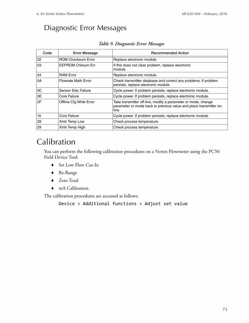
6. 83 Series Vortex Flowmeters MI 020-504 – February 2016
Diagnostic Error Messages
CalibrationYou can perform the following calibration procedures on a Vortex Flowmeter using the PC50 Field Device Tool:
Set Low Flow Cut-In
Re-Range
Zero Total
mA Calibration.
The calibration procedures are accessed as follows:
Device > Additional functions > Adjust set value
Table 9. Diagnostic Error Messages
Code Error Message Recommended Action
02 ROM Checksum Error Replace electronic module.
03 EEPROM Chksum Err If this does not clear problem, replace electronic module.
04 RAM Error Replace electronic module.
0A Flowrate Math Error Check transmitter database and correct any problems. If problem persists, replace electronic module.
0C Sensor Elec Failure Cycle power. If problem persists, replace electronic module.
0E Core Failure Cycle power. If problem persists, replace electronic module.
2F Offline Cfg Write Error Take transmitter off-line, modify a parameter or mode, change parameter or mode back to previous value and place transmitter on-line.
10 Core Failure Cycle power. If problem persists, replace electronic module.
28 Xmtr Temp Low Check process temperature.
29 Xmtr Temp High Check process temperature.
73

MI 020-504 – February 2016 6. 83 Series Vortex Flowmeters
Set Low Flow Cut-InThis function permits you to set the low flow cut-in level for the transmitter. You can also set a manual low flow cut-in level. To execute the operation, use the following procedure:
1. Select Low Flow Cut-In from the Adjust set value menu.
2. Follow the prompt to put the device in Manual control mode and select Continue.
3. For a FoxCom device, select the desired Low Flow Cut-In value or select Automatic to set low flow cut-in to lowest setting with no false signal detected under no flow conditions. Select Continue when done.For a HART device, select Increment or Decrement to obtain the desired Low Flow Cut-In value or select Automatic to set low flow cut-in to lowest setting with no false signal detected under no flow conditions. Select Continue when done.
NOTEBefore selecting Automatic, it is important that flow be stopped.
Figure 40. Sample Vortex Low Flow Cut-In Screen
4. Wait while the new Low Flow Cut-In value is set.
5. Follow the prompt to put the device back into Automatic control mode. Select Continue to resume dynamic measurements.
74
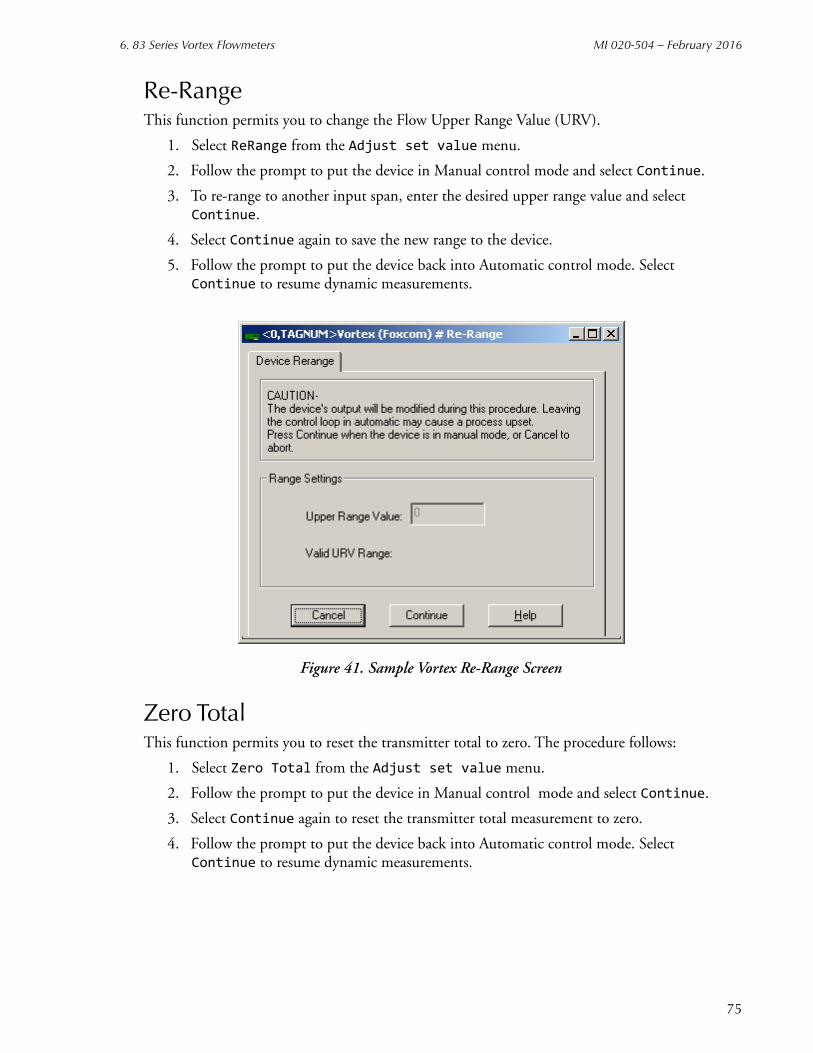
6. 83 Series Vortex Flowmeters MI 020-504 – February 2016
Re-RangeThis function permits you to change the Flow Upper Range Value (URV).
1. Select ReRange from the Adjust set value menu.
2. Follow the prompt to put the device in Manual control mode and select Continue.
3. To re-range to another input span, enter the desired upper range value and select Continue.
4. Select Continue again to save the new range to the device.
5. Follow the prompt to put the device back into Automatic control mode. Select Continue to resume dynamic measurements.
Figure 41. Sample Vortex Re-Range Screen
Zero TotalThis function permits you to reset the transmitter total to zero. The procedure follows:
1. Select Zero Total from the Adjust set value menu.
2. Follow the prompt to put the device in Manual control mode and select Continue.
3. Select Continue again to reset the transmitter total measurement to zero.
4. Follow the prompt to put the device back into Automatic control mode. Select Continue to resume dynamic measurements.
75
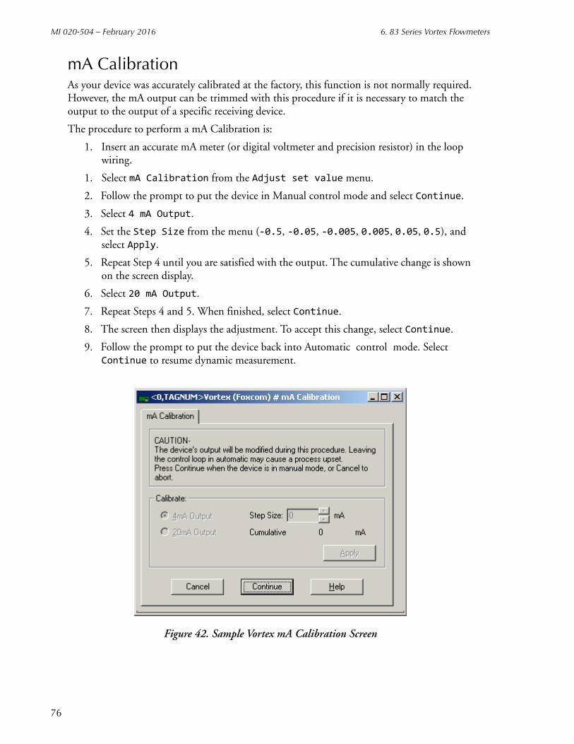
MI 020-504 – February 2016 6. 83 Series Vortex Flowmeters
mA CalibrationAs your device was accurately calibrated at the factory, this function is not normally required. However, the mA output can be trimmed with this procedure if it is necessary to match the output to the output of a specific receiving device.
The procedure to perform a mA Calibration is:
1. Insert an accurate mA meter (or digital voltmeter and precision resistor) in the loop wiring.
1. Select mA Calibration from the Adjust set value menu.
2. Follow the prompt to put the device in Manual control mode and select Continue.
3. Select 4 mA Output.
4. Set the Step Size from the menu (-0.5, -0.05, -0.005, 0.005, 0.05, 0.5), and select Apply.
5. Repeat Step 4 until you are satisfied with the output. The cumulative change is shown on the screen display.
6. Select 20 mA Output.
7. Repeat Steps 4 and 5. When finished, select Continue.
8. The screen then displays the adjustment. To accept this change, select Continue.
9. Follow the prompt to put the device back into Automatic control mode. Select Continue to resume dynamic measurement.
Figure 42. Sample Vortex mA Calibration Screen
76
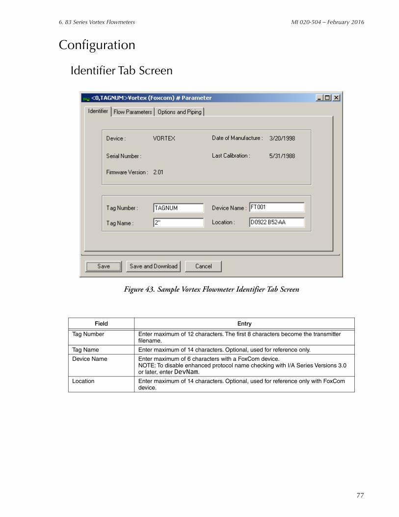
6. 83 Series Vortex Flowmeters MI 020-504 – February 2016
Configuration
Identifier Tab Screen
Figure 43. Sample Vortex Flowmeter Identifier Tab Screen
Field Entry
Tag Number Enter maximum of 12 characters. The first 8 characters become the transmitter filename.
Tag Name Enter maximum of 14 characters. Optional, used for reference only.
Device Name Enter maximum of 6 characters with a FoxCom device.NOTE: To disable enhanced protocol name checking with I/A Series Versions 3.0 or later, enter DevNam.
Location Enter maximum of 14 characters. Optional, used for reference only with FoxCom device.
77
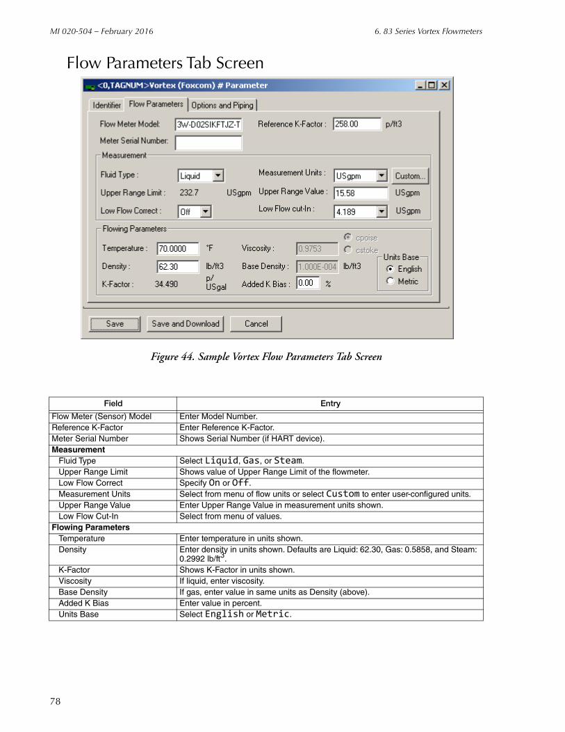
MI 020-504 – February 2016 6. 83 Series Vortex Flowmeters
Flow Parameters Tab Screen
Figure 44. Sample Vortex Flow Parameters Tab Screen
Field Entry
Flow Meter (Sensor) Model Enter Model Number.Reference K-Factor Enter Reference K-Factor.Meter Serial Number Shows Serial Number (if HART device).Measurement
Fluid Type Select Liquid, Gas, or Steam.Upper Range Limit Shows value of Upper Range Limit of the flowmeter.Low Flow Correct Specify On or Off.Measurement Units Select from menu of flow units or select Custom to enter user-configured units.Upper Range Value Enter Upper Range Value in measurement units shown.Low Flow Cut-In Select from menu of values.
Flowing ParametersTemperature Enter temperature in units shown.Density Enter density in units shown. Defaults are Liquid: 62.30, Gas: 0.5858, and Steam:
0.2992 lb/ft3.K-Factor Shows K-Factor in units shown.Viscosity If liquid, enter viscosity.Base Density If gas, enter value in same units as Density (above).Added K Bias Enter value in percent.Units Base Select English or Metric.
78
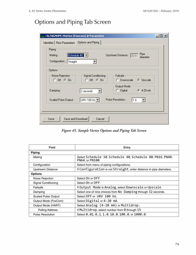
6. 83 Series Vortex Flowmeters MI 020-504 – February 2016
Options and Piping Tab Screen
Figure 45. Sample Vortex Options and Piping Tab Screen
Field Entry
Piping
Mating Select Schedule 10, Schedule 40, Schedule 80, PN16, PN40, PN64, or PN100.
Configuration Select from menu of piping configurations.
Upstream Distance If Configuration is not Straight, enter distance in pipe diameters.
Options
Noise Rejection Select On or Off.
Signal Conditioning Select On or Off.
Failsafe If Output Mode is Analog, select Downscale or Upscale.
Damping Select one of nine choices from No Damping through 32 seconds.
Scaled Pulse Output Select Off or URV 100 Hz.
Output Mode (FoxCom) Select Digital or 4-20 mA.
Output Mode (HART) Select Analog (4-20 mA) or Multidrop.
Polling Address If Multidrop, select number from 0 through 15.
Pulse Resolution Select 0.01, 0.1, 1.0, 10.0, 100.0, or 1000.0.
79

MI 020-504 – February 2016 6. 83 Series Vortex Flowmeters
80

7. 870ITEC Transmitters
This chapter provides information that is exclusive to using the PC50 Field Device Tool with 870ITEC Electrochemical Transmitters with FoxCom communication protocol. Additional information about these transmitters and FoxCom communication is contained in the following documents.
B0193XXChecklist for FoxCom Measurement Integration
MI 611-212Installation, Operation, Configuration, and Maintenance.
Measure Screen
Figure 46. Sample 870ITEC Measure Screen
Error MessagesThe Diagnosis function is described in Chapter 1 of this document. A sample diagnosis screen is shown in Figure 1. Explanation and recommended action of status error messages is given in Table 10
81

MI 020-504 – February 2016 7. 870ITEC Transmitters
Table 10. Transmitter Status Error Messages
Message Explanation Recommended Action
Primary Status Fields
Device Busy Transmitter is busy. If problem persists, select Device > Additional Functions > Commands > Mode Change > On-Line. If this does not clear problem, contact Global Customer Support.
Init Required Transmitter is re-initializing onreset.
If problem persists, select Device > Additional Functions > Commands > Mode Change > On-Line. If this does not clear problem, contact Global Customer Support.
Diagnostic Error Indicates an activediagnostic error.
See diagnostic error message to determine problem and corrective action.
Secondary StatusError
Indicates an error insecondary status.
The secondary status error is shown in Column 2 of the screen display.
Secondary Status Fields
MeasurementError
Unstable processmeasurement.
Check sensor connection. Select Device > Additional Functions > Commands > Mode Change > On-Line. If this does not clear problem, contact Global Customer Support.
Device Busy Transmitter is busy. If problem persists, select Device > Additional Functions > Commands > Mode Change > On-Line. If this does not clear problem, contact Global Customer Support.
Bad MessageReceived
Transmitter receiveda bad message.
Select TDevice > Additional Functions > Commands > Mode Change > On-Line. If this does not clear problem, contact Global Customer Support.
Stability Error Raw measurement hasbeen unstable.
Check wiring. Select Device > Additional Functions > Commands > Mode Change > On-Line. If this does not clear problem, contact Global Customer Support.
Probe Error Problem with the sensor. Replace sensor.
Temp Comp Error Problem in temperaturemeasurement.
Check ATC connection. Verify process temperature. Select Device > Additional Functions > Commands > Mode Change > On-Line. If this does not clear problem, contact Global Customer Support.
Amplifier Error Not Applicable Not Applicable
Extended Status - Hardware (a)
ATC Open Resistance of temperaturecompensation is greater or less than expected resistance of device configured.
Replace temperature compensator.
ATC Short
Leak Error Solution leakage into sensor. Replace sensor.
App1 Cal Req Application 1 calibrationrequired.
Calibrate.
App2 Cal Req Application 2 calibrationrequired.
Calibrate.
App3 Cal Req Application 3 calibrationrequired.
Calibrate.
Cal Comp Error Indicates a problem inthe previous calibration.
Recalibrate the transmitter. If problem persists, contact Global Customer Support.
Cal Slope Error Not Applicable. Not Applicable.
82
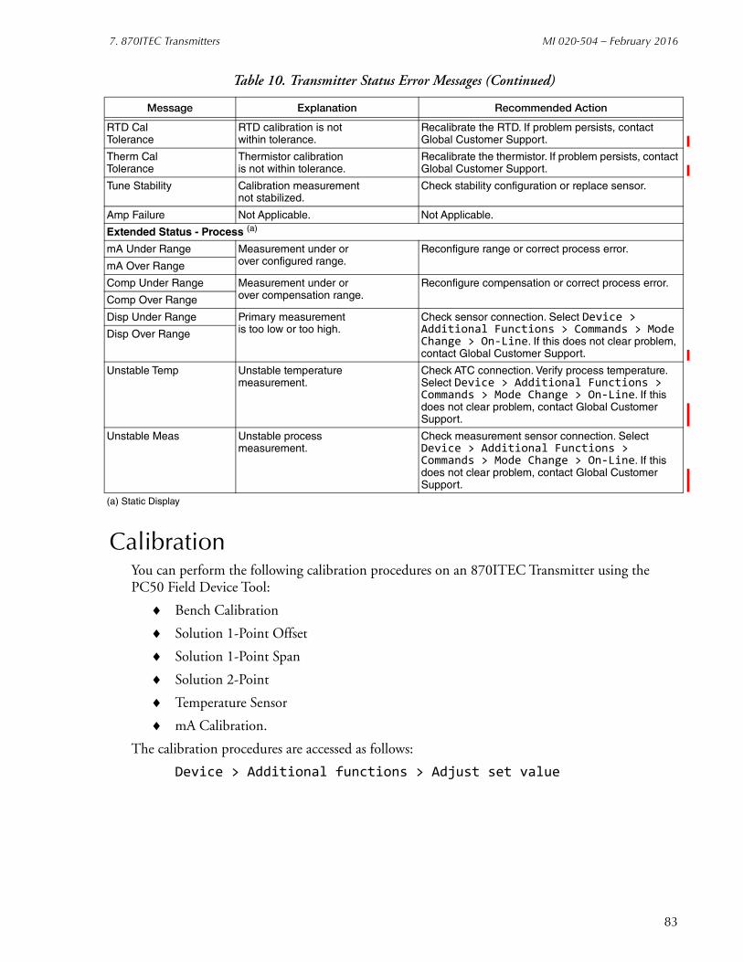
7. 870ITEC Transmitters MI 020-504 – February 2016
CalibrationYou can perform the following calibration procedures on an 870ITEC Transmitter using the PC50 Field Device Tool:
Bench Calibration
Solution 1-Point Offset
Solution 1-Point Span
Solution 2-Point
Temperature Sensor
mA Calibration.
The calibration procedures are accessed as follows:
Device > Additional functions > Adjust set value
RTD CalTolerance
RTD calibration is notwithin tolerance.
Recalibrate the RTD. If problem persists, contact Global Customer Support.
Therm CalTolerance
Thermistor calibrationis not within tolerance.
Recalibrate the thermistor. If problem persists, contact Global Customer Support.
Tune Stability Calibration measurementnot stabilized.
Check stability configuration or replace sensor.
Amp Failure Not Applicable. Not Applicable.
Extended Status - Process (a)
mA Under Range Measurement under orover configured range.
Reconfigure range or correct process error.
mA Over Range
Comp Under Range Measurement under orover compensation range.
Reconfigure compensation or correct process error.
Comp Over Range
Disp Under Range Primary measurementis too low or too high.
Check sensor connection. Select Device > Additional Functions > Commands > Mode Change > On-Line. If this does not clear problem, contact Global Customer Support.
Disp Over Range
Unstable Temp Unstable temperaturemeasurement.
Check ATC connection. Verify process temperature. Select Device > Additional Functions > Commands > Mode Change > On-Line. If this does not clear problem, contact Global Customer Support.
Unstable Meas Unstable processmeasurement.
Check measurement sensor connection. Select Device > Additional Functions > Commands > Mode Change > On-Line. If this does not clear problem, contact Global Customer Support.
(a) Static Display
Table 10. Transmitter Status Error Messages (Continued)
Message Explanation Recommended Action
83
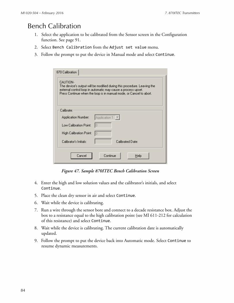
MI 020-504 – February 2016 7. 870ITEC Transmitters
Bench Calibration1. Select the application to be calibrated from the Sensor screen in the Configuration
function. See page 91.
2. Select Bench Calibration from the Adjust set value menu.
3. Follow the prompt to put the device in Manual mode and select Continue.
Figure 47. Sample 870ITEC Bench Calibration Screen
4. Enter the high and low solution values and the calibrator’s initials, and select Continue.
5. Place the clean dry sensor in air and select Continue.
6. Wait while the device is calibrating.
7. Run a wire through the sensor bore and connect to a decade resistance box. Adjust the box to a resistance equal to the high calibration point (see MI 611-212 for calculation of this resistance) and select Continue.
8. Wait while the device is calibrating. The current calibration date is automatically updated.
9. Follow the prompt to put the device back into Automatic mode. Select Continue to resume dynamic measurements.
84
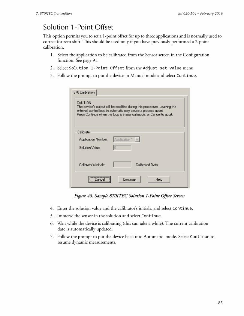
7. 870ITEC Transmitters MI 020-504 – February 2016
85
Solution 1-Point OffsetThis option permits you to set a 1-point offset for up to three applications and is normally used to correct for zero shift. This should be used only if you have previously performed a 2-point calibration.
1. Select the application to be calibrated from the Sensor screen in the Configuration function. See page 91.
2. Select Solution 1-Point Offset from the Adjust set value menu.
3. Follow the prompt to put the device in Manual mode and select Continue.
Figure 48. Sample 870ITEC Solution 1-Point Offset Screen
4. Enter the solution value and the calibrator’s initials, and select Continue.
5. Immerse the sensor in the solution and select Continue.
6. Wait while the device is calibrating (this can take a while). The current calibration date is automatically updated.
7. Follow the prompt to put the device back into Automatic mode. Select Continue to resume dynamic measurements.
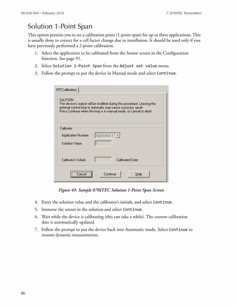
MI 020-504 – February 2016 7. 870ITEC Transmitters
Solution 1-Point SpanThis option permits you to set a calibration point (1-point span) for up to three applications. This is usually done to correct for a cell factor change due to installation. It should be used only if you have previously performed a 2-point calibration.
1. Select the application to be calibrated from the Sensor screen in the Configuration function. See page 91.
2. Select Solution 1-Point Span from the Adjust set value menu.
3. Follow the prompt to put the device in Manual mode and select Continue.
Figure 49. Sample 870ITEC Solution 1-Point Span Screen
4. Enter the solution value and the calibrator’s initials, and select Continue.
5. Immerse the sensor in the solution and select Continue.
6. Wait while the device is calibrating (this can take a while). The current calibration date is automatically updated.
7. Follow the prompt to put the device back into Automatic mode. Select Continue to resume dynamic measurements.
86

7. 870ITEC Transmitters MI 020-504 – February 2016
Solution 2-PointThis option permits you to perform a 2-point calibration for up to three applications.
1. Select the application to be calibrated from the Sensor screen in the Configuration function. See page 91.
2. Select Solution 2-Point from the Adjust set value menu.
3. Follow the prompt to put the device in Manual mode and select Continue.
Figure 50. Sample 870ITEC Solution 2-Point Calibration Screen
4. Enter the low and high solution values and the calibrator’s initials, and select Continue.
5. Immerse the sensor in the low calibration solution and select Continue.
6. Wait while the device is calibrating (this can take a while).
7. Immerse the sensor in the high calibration solution and select Continue.
8. Wait while the device is calibrating (this can take a while). The current calibration date is automatically updated.
9. Follow the prompt to put the device back into Automatic mode. Select Continue to resume dynamic measurements.
87

MI 020-504 – February 2016 7. 870ITEC Transmitters
Temperature Sensor CalibrationThis option permits you to calibrate the temperature sensor to the known temperature of a solution.
1. Select the application to be calibrated from the Sensor screen in the Configuration function. See page 91.
2. Select Temperature Sensor from the Adjust set value menu.
3. Follow the prompt to put the device in Manual mode and select Continue.
Figure 51. Sample 870ITEC Temperature Calibration
4. Enter the solution temperature and the calibrator’s initials, and select Continue.
5. Immerse the sensor in the solution and select Continue.
6. Follow the prompt to put the device back into Automatic mode. Select Continue to resume dynamic measurements.
88
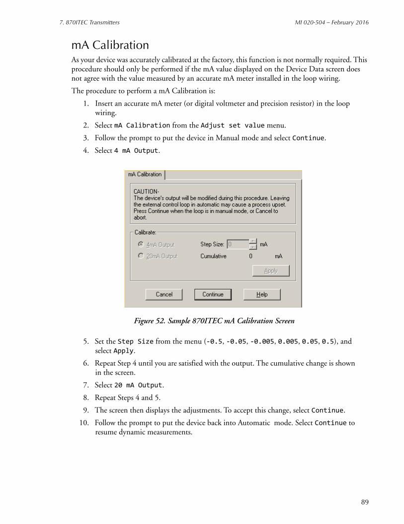
7. 870ITEC Transmitters MI 020-504 – February 2016
mA CalibrationAs your device was accurately calibrated at the factory, this function is not normally required. This procedure should only be performed if the mA value displayed on the Device Data screen does not agree with the value measured by an accurate mA meter installed in the loop wiring.
The procedure to perform a mA Calibration is:
1. Insert an accurate mA meter (or digital voltmeter and precision resistor) in the loop wiring.
2. Select mA Calibration from the Adjust set value menu.
3. Follow the prompt to put the device in Manual mode and select Continue.
4. Select 4 mA Output.
Figure 52. Sample 870ITEC mA Calibration Screen
5. Set the Step Size from the menu (-0.5, -0.05, -0.005, 0.005, 0.05, 0.5), and select Apply.
6. Repeat Step 4 until you are satisfied with the output. The cumulative change is shown in the screen.
7. Select 20 mA Output.
8. Repeat Steps 4 and 5.
9. The screen then displays the adjustments. To accept this change, select Continue.
10. Follow the prompt to put the device back into Automatic mode. Select Continue to resume dynamic measurements.
89

MI 020-504 – February 2016 7. 870ITEC Transmitters
Configuration
Identifier Tab Screen
Figure 53. Sample 870ITEC Identifier Tab Screen
Field Entry
Tag Number Enter maximum of 12 characters. The first 8 characters become the transmitter filename.
Tag Name Enter maximum of 14 characters. Optional, used for reference only.
Device Name Enter maximum of 6 characters.NOTE: To disable enhanced protocol name checking with I/A Series Versions 3.0 or later, enter DevNam.
Location Enter maximum of 14 characters. Optional, used for reference only.
90

7. 870ITEC Transmitters MI 020-504 – February 2016
Sensor Tab Screen
Figure 54. Sample 870ITEC Sensor Tab Screen
Field Entry
Sensor Configuration
Applications Number of applications to be configured. Select 1, 2, or 3 applications.
Application Select Select 1, 2, 3 or AUTO.
Sensor Type Select type of sensor from menu of choices.
Cell Factor If sensor type is OTHER, specify cell factor between 00.00 and 99.99.
Outputs
mA Output Mode Select Digital or 4-20 mA.
Damping Select damping response time of 1, 5, 10, 20, 40, or 120 seconds.
91
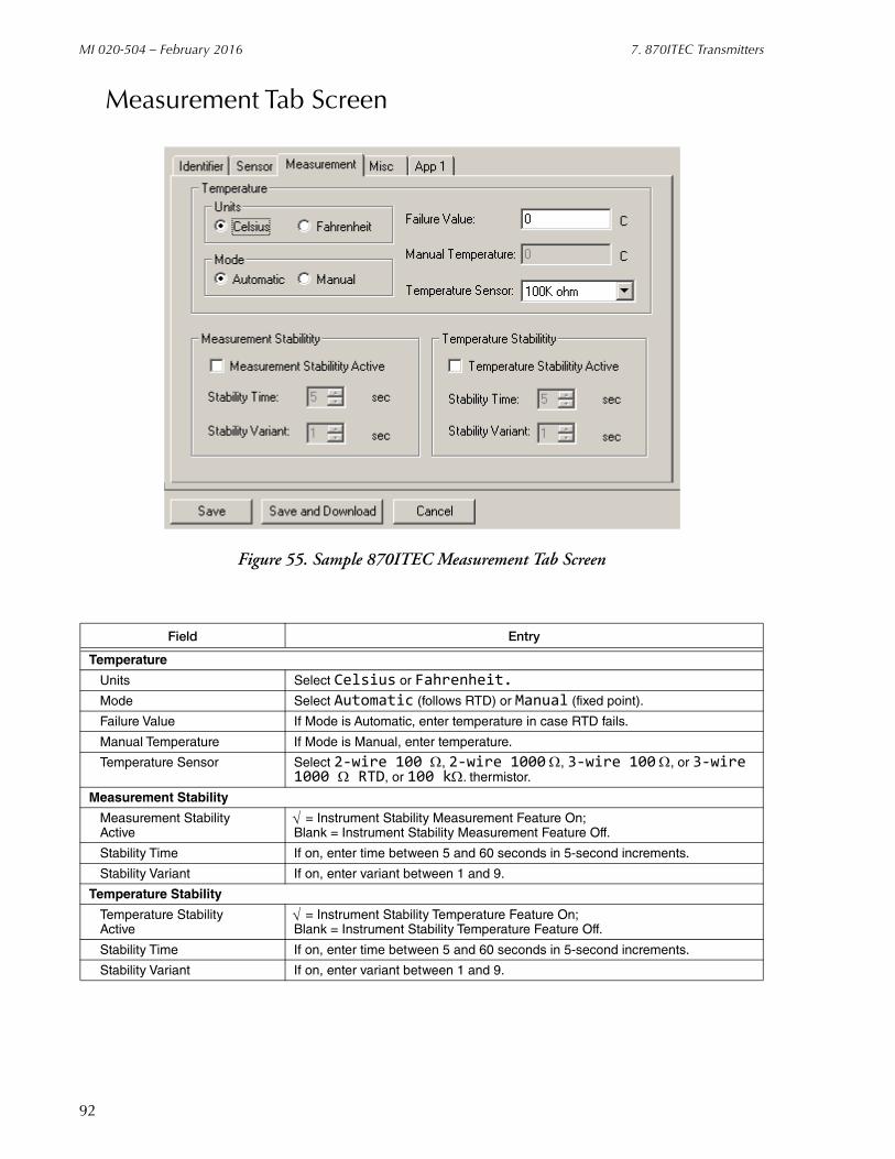
MI 020-504 – February 2016 7. 870ITEC Transmitters
Measurement Tab Screen
Figure 55. Sample 870ITEC Measurement Tab Screen
Field Entry
Temperature
Units Select Celsius or Fahrenheit.
Mode Select Automatic (follows RTD) or Manual (fixed point).
Failure Value If Mode is Automatic, enter temperature in case RTD fails.
Manual Temperature If Mode is Manual, enter temperature.
Temperature Sensor Select 2-wire 100 , 2-wire 1000 , 3-wire 100 , or 3-wire 1000 RTD, or 100 k. thermistor.
Measurement Stability
Measurement StabilityActive
= Instrument Stability Measurement Feature On; Blank = Instrument Stability Measurement Feature Off.
Stability Time If on, enter time between 5 and 60 seconds in 5-second increments.
Stability Variant If on, enter variant between 1 and 9.
Temperature Stability
Temperature StabilityActive
= Instrument Stability Temperature Feature On; Blank = Instrument Stability Temperature Feature Off.
Stability Time If on, enter time between 5 and 60 seconds in 5-second increments.
Stability Variant If on, enter variant between 1 and 9.
92
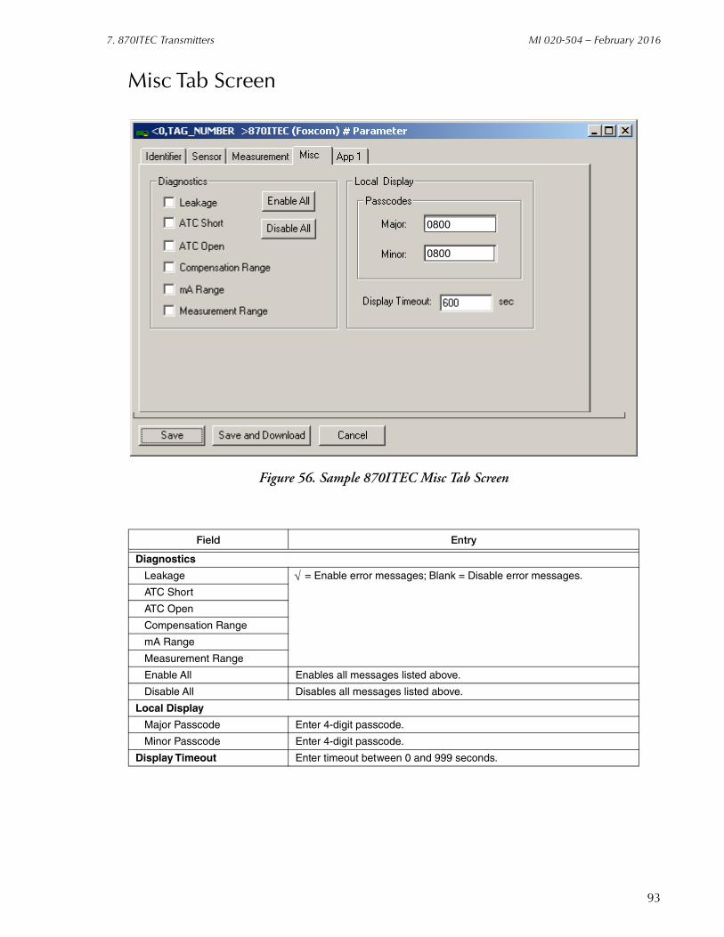
7. 870ITEC Transmitters MI 020-504 – February 2016
Misc Tab Screen
Figure 56. Sample 870ITEC Misc Tab Screen
Field Entry
Diagnostics
Leakage = Enable error messages; Blank = Disable error messages.
ATC Short
ATC Open
Compensation Range
mA Range
Measurement Range
Enable All Enables all messages listed above.
Disable All Disables all messages listed above.
Local Display
Major Passcode Enter 4-digit passcode.
Minor Passcode Enter 4-digit passcode.
Display Timeout Enter timeout between 0 and 999 seconds.
0800
0800
93

MI 020-504 – February 2016 7. 870ITEC Transmitters
Application Tab Screen
Figure 57. Sample 870ITEC App1 Tab Screen
Field Entry
DisplayCustom Units = Custom; Blank = Not Custom
Primary Units If not Custom, select µS/cm, mS/cm, or %.If Custom, select %, g/l, ppm, oz/gal, ppt, S/m, or NONE and see Figure 58.
Temp Compensation Select from menu of choices. If Custom, see Figure 59.
Primary Scale Select from menu of choices.
Full Scale Enter value up to full scale limit.Temp Linear % Enter value from 0 to 100,
Secondary Display Select Temp, Absolute, or mA.
mA OutputOutput If Analog Output Mode on sensor screen, specify Absolute,
Measurement, or Temperature.
Max. Enter 20 mA range value.Min. Enter 4 mA range value.
FailsafeMode Specify OFF, ON, or PULSEValue If on, enter dc mA output between 3.8 and 20.5 mA.
Application Switch Triggers Enter value of Low and High triggers.
94

7. 870ITEC Transmitters MI 020-504 – February 2016
Figure 58. Custom Chemical Compensation Screen
Figure 59. Custom Temperature Compensation Screen
95

MI 020-504 – February 2016 7. 870ITEC Transmitters
96

8. 870ITPH pH/ORP/ISE Transmitters
This chapter provides information that is exclusive to using the PC50 Field Device Tool with 870ITPH pH/ORP/ISE Transmitters with FoxCom communication protocol. Additional information about these transmitters and FoxCom communication is contained in the following documents.
B0193XXChecklist for FoxCom Measurement Integration
MI 611-211Installation, Operation, Configuration, and Maintenance.
Measure Screen
Figure 60. Sample 870ITPH Measure Screen
Error MessagesThe Diagnosis function is described in Chapter 1 of this document. A sample diagnosis screen is shown in Figure 1. Explanation and recommended action of status error messages is given in Table 11.
97

MI 020-504 – February 2016 8. 870ITPH pH/ORP/ISE Transmitters
Table 11. Transmitter Status Error Messages
Message Explanation Recommended Action
Primary Status Fields
Device Busy Transmitter is busy. If problem persists, select Device > Additional Functions > Commands > Mode Change > On-Line. If this does not clear problem, contact Global Customer Support.
Init Required Transmitter is re-initializing on reset.
If problem persists, select Device > Additional Functions > Commands > Mode Change > On-Line. If this does not clear problem, contact Global Customer Support.
Diagnostic Error Indicates an activediagnostic error.
See diagnostic error message to determine problem and corrective action.
Secondary Status Error
Indicates an error insecondary status.
The secondary status error is shown in Column 2 of the screen display.
Secondary Status Fields
MeasurementError
Unstable processmeasurement.
Check sensor connection. Select Device > Additional Functions > Commands > Mode Change > On-Line. If this does not clear problem, contact Global Customer Support.
Device Busy Transmitter is busy. If problem persists, select Device > Additional Functions > Commands > Mode Change > On-Line. If this does not clear problem, contact Global Customer Support.
Bad MessageReceived
Transmitter receiveda bad message.
Select Test > Go On-Line. If this does not clear problem, contact Global Customer Support.
Stability Error Raw measurementhas been unstable.
Check wiring. Select Device > Additional Functions > Commands > Mode Change > On-Line. If this does not clear problem, contact Global Customer Support.
Probe Error Indicates an errorwith the probe.
If Coat error, clean probe. If Lowslope error, replace buffer solution (if contaminated). For other problems, replace probe.
Temp CompError
Problem in temperature measurement.
Check ATC connection. Verify process temperature. Select Device > Additional Functions > Commands > Mode Change > On-Line. If this does not clear problem, contact Global Customer Support.
Amplifier Error Out of range error. Check probe. Select Device > Additional Functions > Commands > Mode Change > On-Line. If this does not clear problem, contact Global Customer Support.
Extended Status - Hardware (a)
ATC Open Resistance oftemperaturecompensation isless than expectedresistance of deviceconfigured.
Replace temperature compensator.
ATC Short Resistance oftemperaturecompensation isgreater than expectedresistance of deviceconfigured.
Replace temperature compensator.
Coat Error Reference junctionresistance in relation tosolution ground isless than user set limit.
Clean electrode.
98
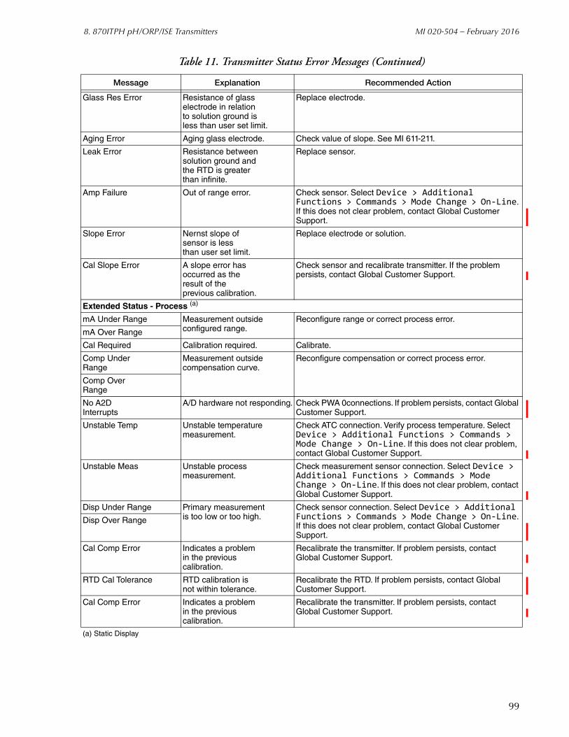
8. 870ITPH pH/ORP/ISE Transmitters MI 020-504 – February 2016
Glass Res Error Resistance of glasselectrode in relationto solution ground isless than user set limit.
Replace electrode.
Aging Error Aging glass electrode. Check value of slope. See MI 611-211.
Leak Error Resistance betweensolution ground andthe RTD is greaterthan infinite.
Replace sensor.
Amp Failure Out of range error. Check sensor. Select Device > Additional Functions > Commands > Mode Change > On-Line. If this does not clear problem, contact Global Customer Support.
Slope Error Nernst slope ofsensor is lessthan user set limit.
Replace electrode or solution.
Cal Slope Error A slope error hasoccurred as theresult of theprevious calibration.
Check sensor and recalibrate transmitter. If the problem persists, contact Global Customer Support.
Extended Status - Process (a)
mA Under Range Measurement outsideconfigured range.
Reconfigure range or correct process error.
mA Over Range
Cal Required Calibration required. Calibrate.
Comp UnderRange
Measurement outsidecompensation curve.
Reconfigure compensation or correct process error.
Comp OverRange
No A2DInterrupts
A/D hardware not responding. Check PWA 0connections. If problem persists, contact Global Customer Support.
Unstable Temp Unstable temperaturemeasurement.
Check ATC connection. Verify process temperature. Select Device > Additional Functions > Commands > Mode Change > On-Line. If this does not clear problem, contact Global Customer Support.
Unstable Meas Unstable processmeasurement.
Check measurement sensor connection. Select Device > Additional Functions > Commands > Mode Change > On-Line. If this does not clear problem, contact Global Customer Support.
Disp Under Range Primary measurementis too low or too high.
Check sensor connection. Select Device > Additional Functions > Commands > Mode Change > On-Line. If this does not clear problem, contact Global Customer Support.
Disp Over Range
Cal Comp Error Indicates a problemin the previouscalibration.
Recalibrate the transmitter. If problem persists, contact Global Customer Support.
RTD Cal Tolerance RTD calibration isnot within tolerance.
Recalibrate the RTD. If problem persists, contact Global Customer Support.
Cal Comp Error Indicates a problemin the previouscalibration.
Recalibrate the transmitter. If problem persists, contact Global Customer Support.
(a) Static Display
Table 11. Transmitter Status Error Messages (Continued)
Message Explanation Recommended Action
99

MI 020-504 – February 2016 8. 870ITPH pH/ORP/ISE Transmitters
CalibrationYou can perform the following calibration procedures on an 870ITPH Transmitter using the PC50 Field Device Tool:
One Point Manual Calibration
One Point Absolute Calibration
Two Point Manual Calibration
mA Calibration.
Automatic Calibration
Temperature Sensor
The calibration procedures are accessed as follows:
Device > Additional functions > Adjust set value
100
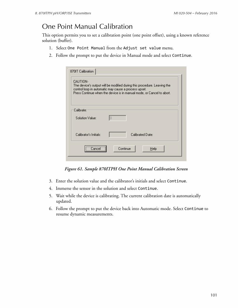
8. 870ITPH pH/ORP/ISE Transmitters MI 020-504 – February 2016
One Point Manual CalibrationThis option permits you to set a calibration point (one point offset), using a known reference solution (buffer).
1. Select One Point Manual from the Adjust set value menu.
2. Follow the prompt to put the device in Manual mode and select Continue.
Figure 61. Sample 870ITPH One Point Manual Calibration Screen
3. Enter the solution value and the calibrator’s initials and select Continue.
4. Immerse the sensor in the solution and select Continue.
5. Wait while the device is calibrating. The current calibration date is automatically updated.
6. Follow the prompt to put the device back into Automatic mode. Select Continue to resume dynamic measurements.
101
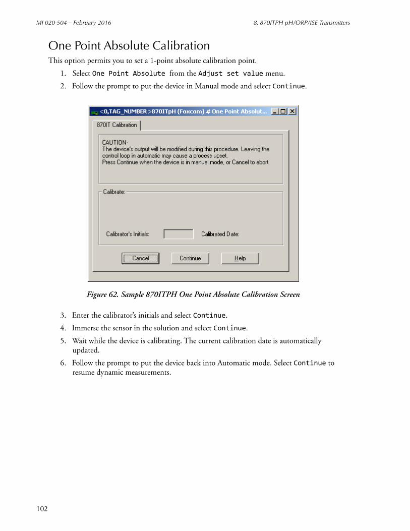
MI 020-504 – February 2016 8. 870ITPH pH/ORP/ISE Transmitters
One Point Absolute CalibrationThis option permits you to set a 1-point absolute calibration point.
1. Select One Point Absolute from the Adjust set value menu.
2. Follow the prompt to put the device in Manual mode and select Continue.
Figure 62. Sample 870ITPH One Point Absolute Calibration Screen
3. Enter the calibrator’s initials and select Continue.
4. Immerse the sensor in the solution and select Continue.
5. Wait while the device is calibrating. The current calibration date is automatically updated.
6. Follow the prompt to put the device back into Automatic mode. Select Continue to resume dynamic measurements.
102

8. 870ITPH pH/ORP/ISE Transmitters MI 020-504 – February 2016
Two Point Manual CalibrationThis option permits you to set span and offset, using two known reference solutions (buffers).
1. Select Two Point Manual from the Adjust set value menu.
2. Follow the prompt to put the device in Manual mode and select Continue.
Figure 63. Sample 870ITPH Two Point Manual Calibration Screen
3. Enter the high and low solution values and the calibrator’s initials and select Continue.
4. Immerse the sensor in the low solution and select Continue.
5. Wait while the device is calibrating.
6. Immerse the sensor in the high solution and select Continue.
7. Wait while the device is calibrating. The current calibration date is automatically updated.
8. Follow the prompt to put the device back into Automatic mode. Select Continue to resume dynamic measurements.
103

MI 020-504 – February 2016 8. 870ITPH pH/ORP/ISE Transmitters
mA CalibrationAs your device was accurately calibrated at the factory, this function is not normally required. However, the mA output can be trimmed with this procedure if it is necessary to match the output to the output of a specific receiving device.
The procedure to perform a mA Output Calibration is:
1. Insert an accurate mA meter (or digital voltmeter and precision resistor) in the loop wiring.
2. Select mA Output from the Adjust set value menu.
3. Follow the prompt to put the device in Manual mode and select Continue.
4. Select 4 mA Output.
5. Set the Step Size (-0.5, -0.05, -0.005, 0.005, 0.05, 0.5), and select Apply.
6. Repeat Step 4 until you are satisfied with the output. The cumulative change is shown on the screen display.
7. Select 20 mA Output.
8. Repeat Steps 4 and 5. When finished, select Continue.
9. The screen then displays the adjustments. To accept this change, select Continue.
10. Follow the prompt to put the device back into Automatic mode. Select Continue to resume dynamic measurement.
Figure 64. Sample 870ITPH mA Calibration Screen
104
8. 870ITPH pH/ORP/ISE Transmitters MI 020-504 – February 2016
Automatic CalibrationThis option provides a buffer-recognition mechanism that locks in the buffer value representing millivolts and temperature being reported from the sensor, using known reference solutions. The algorithm checks each buffer starting with Buffer 1 and selects the first one for which this pH is within 0.5 pH of the average pH for the buffer. If not within 0.5 pH of any buffer table, no buffer is selected.
NOTEThe type of buffer is selected in the Configuration Sensor Tab Screen (see page 108).
1. Select Automatic Calibration from the Adjust set value menu.
2. Follow the prompt to put the device in Manual mode and select Continue.
3. Enter the calibrator’s initials and select Continue.
4. Immerse the sensor in the low solution and select Continue.
5. Wait while the device is calibrating.
6. Immerse the sensor in the high solution and select Continue.
7. Wait while the device is calibrating. The current calibration date is automatically updated.
8. Follow the prompt to put the device back into Automatic mode. Select Continue to resume dynamic measurements.
105
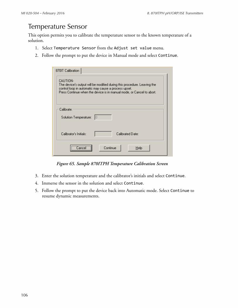
MI 020-504 – February 2016 8. 870ITPH pH/ORP/ISE Transmitters
Temperature SensorThis option permits you to calibrate the temperature sensor to the known temperature of a solution.
1. Select Temperature Sensor from the Adjust set value menu.
2. Follow the prompt to put the device in Manual mode and select Continue.
Figure 65. Sample 870ITPH Temperature Calibration Screen
3. Enter the solution temperature and the calibrator’s initials and select Continue.
4. Immerse the sensor in the solution and select Continue.
5. Follow the prompt to put the device back into Automatic mode. Select Continue to resume dynamic measurements.
106
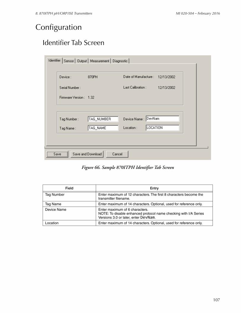
8. 870ITPH pH/ORP/ISE Transmitters MI 020-504 – February 2016
Configuration
Identifier Tab Screen
Figure 66. Sample 870ITPH Identifier Tab Screen
Field Entry
Tag Number Enter maximum of 12 characters. The first 8 characters become the transmitter filename.
Tag Name Enter maximum of 14 characters. Optional, used for reference only.
Device Name Enter maximum of 6 characters.NOTE: To disable enhanced protocol name checking with I/A Series Versions 3.0 or later, enter DevNam.
Location Enter maximum of 14 characters. Optional, used for reference only.
107

MI 020-504 – February 2016 8. 870ITPH pH/ORP/ISE Transmitters
Sensor Tab Screen
Figure 67. Sample 870ITPH Sensor Tab Screen
Field Entry
Sensor
Type Select pH, ISE, or ORP.
Electrode If pH, select Glass, Antimony, or Other.If ISE, select Positive or Negative.
Buffers If pH, select American, NIST, European, or Special (see Figure 68). This parameter is used with Automatic Calibration.
Resolution Scale If pH, select 0.1 pH or 0.01 pH.
Temp. Compensation If pH, select Standard, Ammonia, or Custom (see Figure 69).If ISE, select Standard or Custom.
Chem. Compensation If ISE, select Standard or Custom (see Figure 70).
108

8. 870ITPH pH/ORP/ISE Transmitters MI 020-504 – February 2016
Figure 68. Custom Buffers Screen
Figure 69. Custom Temperature Compensation Screen
109

MI 020-504 – February 2016 8. 870ITPH pH/ORP/ISE Transmitters
Figure 70. Custom Chemical Compensation Screen
110

8. 870ITPH pH/ORP/ISE Transmitters MI 020-504 – February 2016
Output Tab Screen
Figure 71. Sample 870ITPH Output Tab Screen
Field Entry
mA Output
Mode Select Digital or 4-20 mA.
Failsafe Mode If 4-20 mA Mode, specify OFF, ON, or PULSE.
Failsafe Value If ON, enter dc mA output between 3.8 and 20.5 mA.
mA Output If 4-20 mA Mode, specify Absolute, Measurement, or Temperature.
Output Max Value If 4-20 mA Mode, enter 20 mA range value.
Output Min Value If 4-20 mA Mode, enter 4 mA range value.
Local Display
Major Passcode Enter 4-digit passcode.
Minor Passcode Enter 4-digit passcode.
Display Timeout Enter timeout between 0 and 999 seconds.
Secondary Meas Select Temperature, Absolute, or mA.
Damping Select damping response time of 1, 5, 10, 20, 40, or 120 seconds.
AC Frequency Select 50 or 60 Hz.
0800
0800
111
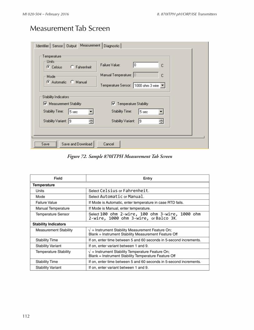
MI 020-504 – February 2016 8. 870ITPH pH/ORP/ISE Transmitters
Measurement Tab Screen
Figure 72. Sample 870ITPH Measurement Tab Screen
Field Entry
Temperature
Units Select Celsius or Fahrenheit.
Mode Select Automatic or Manual.
Failure Value If Mode is Automatic, enter temperature in case RTD fails.
Manual Temperature If Mode is Manual, enter temperature.
Temperature Sensor Select 100 ohm 2-wire, 100 ohm 3-wire, 1000 ohm2-wire, 1000 ohm 3-wire, or Balco 3K.
Stability Indicators
Measurement Stability = Instrument Stability Measurement Feature On; Blank = Instrument Stability Measurement Feature Off
Stability Time If on, enter time between 5 and 60 seconds in 5-second increments.
Stability Variant If on, enter variant between 1 and 9.
Temperature Stability = Instrument Stability Temperature Feature On; Blank = Instrument Stability Temperature Feature Off
Stability Time If on, enter time between 5 and 60 seconds in 5-second increments.
Stability Variant If on, enter variant between 1 and 9.
112
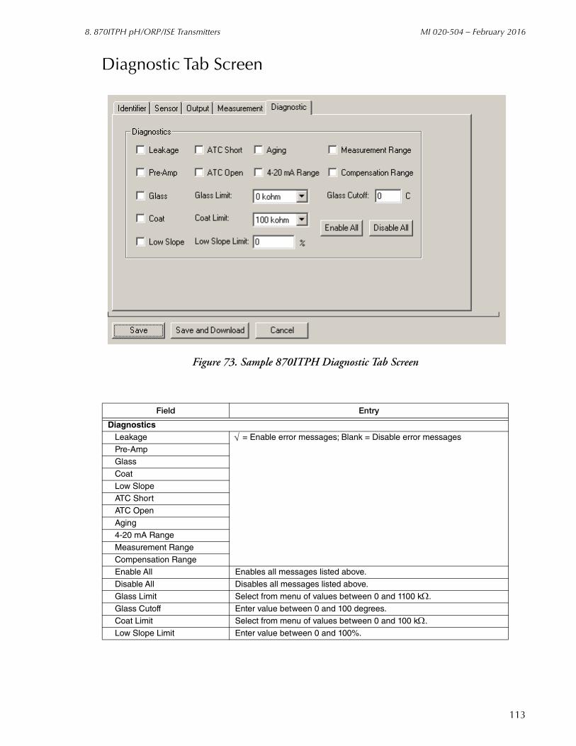
8. 870ITPH pH/ORP/ISE Transmitters MI 020-504 – February 2016
Diagnostic Tab Screen
Figure 73. Sample 870ITPH Diagnostic Tab Screen
Field Entry
DiagnosticsLeakage = Enable error messages; Blank = Disable error messages
Pre-AmpGlass
Coat
Low SlopeATC Short
ATC Open
Aging4-20 mA Range
Measurement Range
Compensation RangeEnable All Enables all messages listed above.
Disable All Disables all messages listed above.
Glass Limit Select from menu of values between 0 and 1100 k.
Glass Cutoff Enter value between 0 and 100 degrees.Coat Limit Select from menu of values between 0 and 100 k.
Low Slope Limit Enter value between 0 and 100%.
113

MI 020-504 – February 2016 8. 870ITPH pH/ORP/ISE Transmitters
114
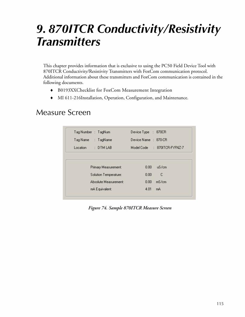
9. 870ITCR Conductivity/Resistivity Transmitters
This chapter provides information that is exclusive to using the PC50 Field Device Tool with 870ITCR Conductivity/Resistivity Transmitters with FoxCom communication protocol. Additional information about these transmitters and FoxCom communication is contained in the following documents.
B0193XXChecklist for FoxCom Measurement Integration
MI 611-216Installation, Operation, Configuration, and Maintenance.
Measure Screen
Figure 74. Sample 870ITCR Measure Screen
115
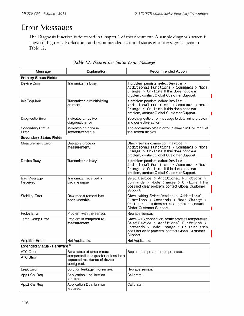
MI 020-504 – February 2016 9. 870ITCR Conductivity/Resistivity Transmitters
Error MessagesThe Diagnosis function is described in Chapter 1 of this document. A sample diagnosis screen is shown in Figure 1. Explanation and recommended action of status error messages is given in Table 12.
Table 12. Transmitter Status Error Messages
Message Explanation Recommended Action
Primary Status Fields
Device Busy Transmitter is busy. If problem persists, select Device > Additional Functions > Commands > Mode Change > On-Line. If this does not clear problem, contact Global Customer Support.
Init Required Transmitter is reinitializingon reset.
If problem persists, select Device > Additional Functions > Commands > Mode Change > On-Line. If this does not clear problem, contact Global Customer Support.
Diagnostic Error Indicates an activediagnostic error.
See diagnostic error message to determine problem and corrective action.
Secondary StatusError
Indicates an error insecondary status.
The secondary status error is shown in Column 2 of the screen display.
Secondary Status Fields
Measurement Error Unstable processmeasurement.
Check sensor connection. Device > Additional Functions > Commands > Mode Change > On-Line. If this does not clear problem, contact Global Customer Support.
Device Busy Transmitter is busy. If problem persists, select Device > Additional Functions > Commands > Mode Change > On-Line. If this does not clear problem, contact Global Customer Support.
Bad MessageReceived
Transmitter received abad message.
Select Device > Additional Functions > Commands > Mode Change > On-Line. If this does not clear problem, contact Global Customer Support.
Stability Error Raw measurement hasbeen unstable.
Check wiring. Select Device > Additional Functions > Commands > Mode Change > On-Line. If this does not clear problem, contact Global Customer Support.
Probe Error Problem with the sensor. Replace sensor.
Temp Comp Error Problem in temperaturemeasurement.
Check ATC connection. Verify process temperature. Select Device > Additional Functions > Commands > Mode Change > On-Line. If this does not clear problem, contact Global Customer Support.
Amplifier Error Not Applicable. Not Applicable.
Extended Status - Hardware (a)
ATC Open Resistance of temperature compensation is greater or less than expected resistance of device configured.
Replace temperature compensator.
ATC Short
Leak Error Solution leakage into sensor. Replace sensor.
App1 Cal Req Application 1 calibrationrequired.
Calibrate.
App2 Cal Req Application 2 calibrationrequired.
Calibrate.
116

9. 870ITCR Conductivity/Resistivity Transmitters MI 020-504 – February 2016
CalibrationYou can perform the following calibration procedures on an 870ITCR Transmitter using the PC50 Field Device Tool:
Solution 1-Point Offset
Solution 1-Point Span
Solution 2-Point
Bench Calibration
Calibration Pure H2O
Temperature Sensor
mA Calibration.
The calibration procedures are accessed as follows:
Device > Additional functions > Adjust set value
App3 Cal Req Application 3 calibrationrequired.
Calibrate.
Cal Comp Error Indicates a problem inthe previous calibration.
Recalibrate the transmitter. If problem persists, contact Global Customer Support.
Cal Slope Error Not Applicable. Not Applicable.
RTD Cal Tolerance RTD calibration is notwithin tolerance.
Recalibrate the RTD. If problem persists, contact Global Customer Support.
Therm CalTolerance
Thermistor calibrationis not within tolerance.
Recalibrate the thermistor. If problem persists, contact Global Customer Support.
Tune Stability Calibration measurementnot stabilized.
Check stability configuration or replace sensor.
Amp Failure Not Applicable. Not Applicable.
Extended Status - Process (a)
mA Under Range Measurement under orover configured range.
Reconfigure range or correct process error.
mA Over Range
Comp Under Range Measurement under orover compensation range.
Reconfigure compensation or correct process error.
Comp Over Range
Disp Under Range Primary measurementis too low or too high.
Check sensor connection. Select Device > Additional Functions > Commands > Mode Change > On-Line. If this does not clear problem, contact Global Customer Support.
Disp Over Range
Unstable Temp Unstable temperaturemeasurement.
Check ATC connection. Verify process temperature. Select Device > Additional Functions > Commands > Mode Change > On-Line. If this does not clear problem, contact Global Customer Support.
Unstable Meas Unstable processmeasurement.
Check measurement sensor connection. Select Device > Additional Functions > Commands > Mode Change > On-Line. If this does not clear problem, contact Global Customer Support.
(a) Static Display
Table 12. Transmitter Status Error Messages (Continued)
Message Explanation Recommended Action
117

MI 020-504 – February 2016 9. 870ITCR Conductivity/Resistivity Transmitters
Solution 1-Point OffsetThis option permits you to set a 1-point offset for up to three applications and is normally used to correct for zero shift. This should be used only if you have previously performed a 2-point calibration.
1. Select the application to be calibrated from the Sensor Tab screen in the Configuration function. See page 125.
2. Select Solution 1-Point Offset from the Adjust set value menu.
3. Follow the prompt to put the device in Manual mode and select Continue.
Figure 75. Sample 870ITCR Solution 1-Point Offset Screen
4. Enter the solution value and the calibrator’s initials, and select Continue.
5. Wait while the device is reinitializing.
6. Immerse the sensor in the solution and select Continue.
7. Wait while the device is calibrating. The current calibration date is automatically updated.
8. Follow the prompt to put the device back into Automatic mode. Select Continue to resume dynamic measurements.
118

9. 870ITCR Conductivity/Resistivity Transmitters MI 020-504 – February 2016
Solution 1-Point SpanThis option permits you to set a calibration point (1-point span) for up to three applications. This is usually done to correct for a cell factor change due to installation. It should be used only if you have previously performed a 2-point calibration. The point selected should be at the high end of the measurement range.
1. Select the application to be calibrated from the Sensor Tab screen in the Configuration function. See page 125.
2. Select Solution 1-Point Span from the Adjust set value menu.
3. Follow the prompt to put the device in Manual mode and select Continue.
Figure 76. Sample 870ITCR Solution 1-Point Span Screen
4. Enter the solution value and the calibrator’s initials, and select Continue.
5. Wait while the device is reinitializing.
6. Immerse the sensor in the solution and select Continue.
7. Wait while the device is calibrating. The current calibration date is automatically updated.
8. Follow the prompt to put the device back into Automatic mode. Select Continue to resume dynamic measurements.
119
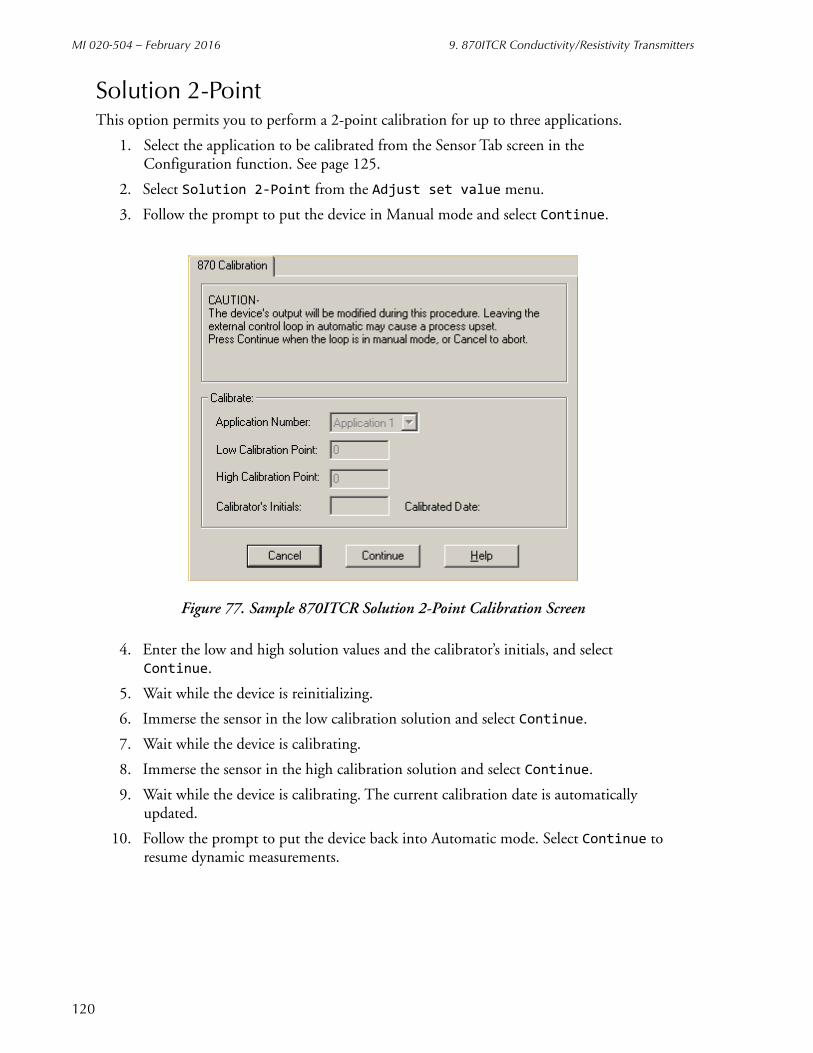
MI 020-504 – February 2016 9. 870ITCR Conductivity/Resistivity Transmitters
Solution 2-PointThis option permits you to perform a 2-point calibration for up to three applications.
1. Select the application to be calibrated from the Sensor Tab screen in the Configuration function. See page 125.
2. Select Solution 2-Point from the Adjust set value menu.
3. Follow the prompt to put the device in Manual mode and select Continue.
Figure 77. Sample 870ITCR Solution 2-Point Calibration Screen
4. Enter the low and high solution values and the calibrator’s initials, and select Continue.
5. Wait while the device is reinitializing.
6. Immerse the sensor in the low calibration solution and select Continue.
7. Wait while the device is calibrating.
8. Immerse the sensor in the high calibration solution and select Continue.
9. Wait while the device is calibrating. The current calibration date is automatically updated.
10. Follow the prompt to put the device back into Automatic mode. Select Continue to resume dynamic measurements.
120
9. 870ITCR Conductivity/Resistivity Transmitters MI 020-504 – February 2016
Bench CalibrationYou can perform a bench calibration for either conductivity or resistivity measurements by connecting your own discrete components to the transmitter.
1. Select the application to be calibrated from the Sensor screen in the Configuration function. See page 125.
2. Select Bench Calibration from the Adjust set value menu.
3. Follow the prompt to put the device in Manual mode and select Continue.
4. Enter the calibrator’s initials, and select Continue.
5. Wait while the device is reinitializing.
6. Follow the prompt to connect Resistor 1 between terminals 1B and 1E and select Continue.
7. Wait while the device is calibrating.
8. Follow the prompt to connect Resistor 2 or the specified capacitor in place of Resistor 1 and select Continue.
9. Wait while the device is calibrating. The current calibration date is automatically updated.
10. Follow the prompt to put the device back into Automatic mode. Select Continue to resume dynamic measurements.
Calibration Pure H2OIf you are measuring purity of water by checking the conductivity in S/cm or resistivity in M•cm with an 871CR-A or 871CR-B sensor, you can use this calibration.
1. Select the application to be calibrated from the Sensor Tab screen in the Configuration function. See page 125.
2. Select Calibration Pure H2O from the Adjust set value menu.
3. Follow the prompt to put the device in Manual mode and select Continue.
4. Enter the temperature cell factor (tCF) and cell factor (CF) found on your sensor. Also enter the calibrator’s initials and select Continue.
5. Follow the prompt to put the device back into Automatic mode. Select Continue to resume dynamic measurements.
121

MI 020-504 – February 2016 9. 870ITCR Conductivity/Resistivity Transmitters
Temperature SensorThis option permits you to calibrate the temperature sensor to the known temperature of a solution.
1. Select the application to be calibrated from the Sensor Tab screen in the Configuration function. See page 125.
2. Select Temperature Sensor from the Adjust set value menu.
3. Follow the prompt to put the device in Manual mode and select Continue.
Figure 78. Sample 870ITCR Temperature Calibration
4. Enter the solution temperature and the calibrator’s initials, and select Continue.
5. Immerse the sensor in the solution and select Continue.
6. Follow the prompt to put the device back into Automatic mode. Select Continue to resume dynamic measurements.
122

9. 870ITCR Conductivity/Resistivity Transmitters MI 020-504 – February 2016
mA CalibrationAs your device was accurately calibrated at the factory, this function is not normally required. However, the mA output can be trimmed with this procedure if it is necessary to match the output to the output of a specific receiving device.
The procedure to perform a mA Output Calibration is:
1. Insert an accurate mA meter (or digital voltmeter and precision resistor) in the loop wiring.
2. Select mA Output from the Adjust set value menu.
3. Follow the prompt to put the device in Manual mode and select Continue.
4. Select 4 mA Output.
5. Set the Step Size (-0.5, -0.05, -0.005, 0.005, 0.05, 0.5), and select Apply.
6. Repeat Step 4 until you are satisfied with the output. The cumulative change is shown on the screen display.
7. Select 20 mA Output.
8. Repeat Steps 4 and 5. When finished, select Continue.
9. The screen then displays the adjustments. To accept this change, select Continue.
10. Follow the prompt to put the device back into Automatic mode. Select Continue to resume dynamic measurement.
Figure 79. Sample 870ITCR mA Calibration Screen
123
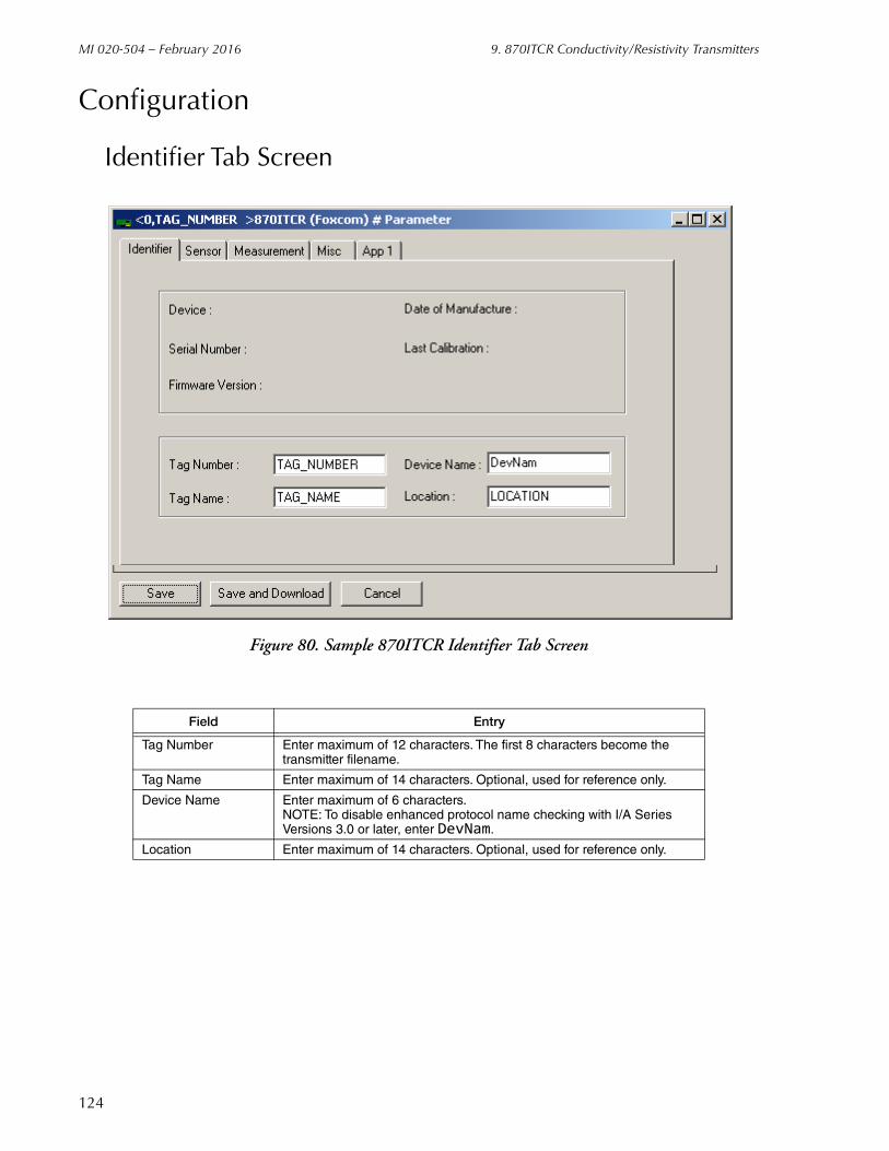
MI 020-504 – February 2016 9. 870ITCR Conductivity/Resistivity Transmitters
Configuration
Identifier Tab Screen
Figure 80. Sample 870ITCR Identifier Tab Screen
Field Entry
Tag Number Enter maximum of 12 characters. The first 8 characters become the transmitter filename.
Tag Name Enter maximum of 14 characters. Optional, used for reference only.
Device Name Enter maximum of 6 characters.NOTE: To disable enhanced protocol name checking with I/A Series Versions 3.0 or later, enter DevNam.
Location Enter maximum of 14 characters. Optional, used for reference only.
124

9. 870ITCR Conductivity/Resistivity Transmitters MI 020-504 – February 2016
Sensor Tab Screen
Figure 81. Sample 870ITCR Sensor Tab Screen
Field Entry
Sensor Configuration
Applications Number of applications to be configured. Select 1, 2, or 3 applications.
Application Select Select 1, 2, 3, or AUTO.
Probe Type Specify 2 Electrode.
Cell Constant Specify 0.1, 10, or Other.
Cell Factor If sensor type is Other, specify cell factor between 00.00 and 99.99.
Outputs
mA Output Mode Select Digital or 4-20 mA.
Damping Select damping response time of 1, 5, 10, 20, 40, or 120 seconds.
125

MI 020-504 – February 2016 9. 870ITCR Conductivity/Resistivity Transmitters
Measurement Tab Screen
Figure 82. Sample 870ITCR Measurement Tab Screen
Field Entry
Temperature
Units Select Celsius or Fahrenheit
Mode Select Automatic (follows RTD) or Manual (fixed point).
Failure Value If Mode is Automatic, enter temperature in case RTD fails.
Manual Temperature If Mode is Manual, enter temperature.
Temperature Sensor Select 2-wire 100 , 2-wire 1000 , 3-wire 100 , or 3-wire 1000 RTD, or 100 k. thermistor.
Measurement Stability
Measurement StabilityActive
= Instrument Stability Measurement Feature On; Blank = Instrument Stability Measurement Feature Off
Stability Time If on, enter time between 5 and 60 seconds in 5-second increments.
Stability Variant If on, enter variant between 1 and 9.
Temperature Stability
Temperature StabilityActive
= Instrument Stability Temperature Feature On; Blank = Instrument Stability Temperature Feature Off
Stability Time If on, enter time between 5 and 60 seconds in 5-second increments.
Stability Variant If on, enter variant between 1 and 9.
126

9. 870ITCR Conductivity/Resistivity Transmitters MI 020-504 – February 2016
Misc Tab Screen
Figure 83. Sample 870ITCR Misc Tab Screen
Field Entry
Diagnostics
Leakage = Enable error messages; Blank = Disable error messages
ATC Short
ATC Open
Compensation Range
mA Range
Measurement Range
Enable All Enables all messages listed above.
Disable All Disables all messages listed above.
Local Display
Major Passcode Enter 4-digit passcode.
Minor Passcode Enter 4-digit passcode.
Display Timeout Enter timeout between 0 and 999 seconds.
0800
0800
127
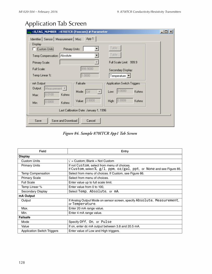
MI 020-504 – February 2016 9. 870ITCR Conductivity/Resistivity Transmitters
Application Tab Screen
Figure 84. Sample 870ITCR App1 Tab Screen
Field Entry
DisplayCustom Units = Custom; Blank = Not CustomPrimary Units If not Custom, select from menu of choices.
If Custom, select %, g/l, ppm, oz/gal, ppt, or None and see Figure 85.
Temp Compensation Select from menu of choices. If Custom, see Figure 86.Primary Scale Select from menu of choices.
Full Scale Enter value up to full scale limit.
Temp Linear % Enter value from 0 to 100,
Secondary Display Select Temp, Absolute, or mA.mA Output
Output If Analog Output Mode on sensor screen, specify Absolute, Measurement, or Temperature.
Max. Enter 20 mA range value.
Min. Enter 4 mA range value.
FailsafeMode Specify Off, On, or PulseValue If on, enter dc mA output between 3.8 and 20.5 mA.
Application Switch Triggers Enter value of Low and High triggers.
128

9. 870ITCR Conductivity/Resistivity Transmitters MI 020-504 – February 2016
Figure 85. Custom Chemical Compensation Screen
Figure 86. Custom Temperature Compensation Screen
129

MI 020-504 – February 2016 9. 870ITCR Conductivity/Resistivity Transmitters
130
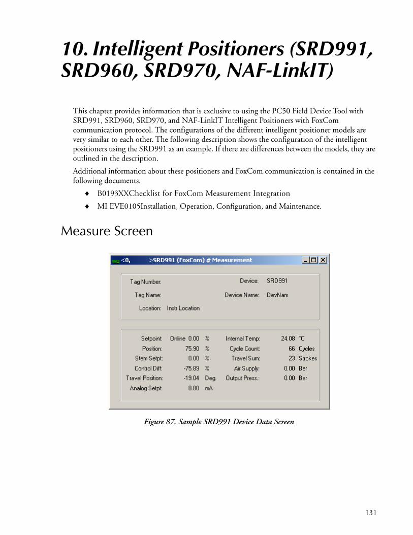
10. Intelligent Positioners (SRD991, SRD960, SRD970, NAF-LinkIT)
This chapter provides information that is exclusive to using the PC50 Field Device Tool with SRD991, SRD960, SRD970, and NAF-LinkIT Intelligent Positioners with FoxCom communication protocol. The configurations of the different intelligent positioner models are very similar to each other. The following description shows the configuration of the intelligent positioners using the SRD991 as an example. If there are differences between the models, they are outlined in the description.
Additional information about these positioners and FoxCom communication is contained in the following documents.
B0193XXChecklist for FoxCom Measurement Integration
MI EVE0105Installation, Operation, Configuration, and Maintenance.
Measure Screen
Figure 87. Sample SRD991 Device Data Screen
131
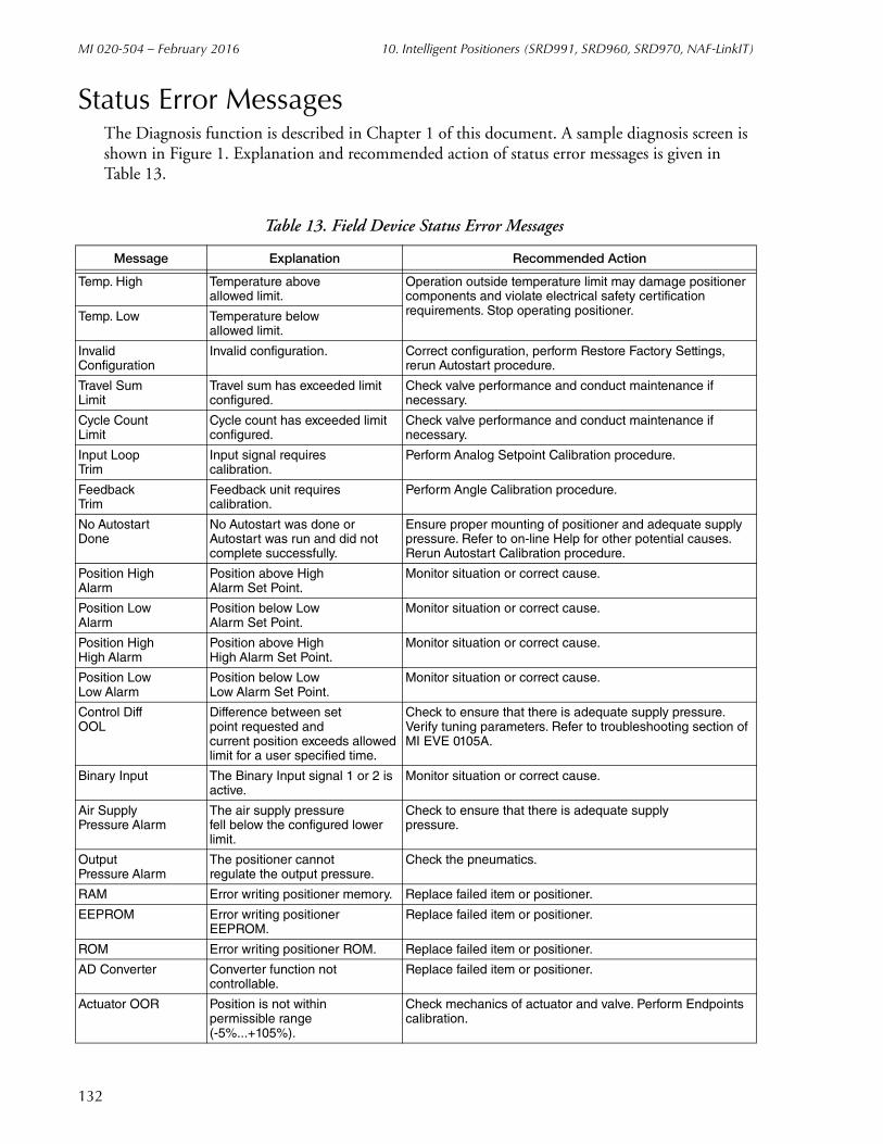
MI 020-504 – February 2016 10. Intelligent Positioners (SRD991, SRD960, SRD970, NAF-LinkIT)
Status Error MessagesThe Diagnosis function is described in Chapter 1 of this document. A sample diagnosis screen is shown in Figure 1. Explanation and recommended action of status error messages is given in Table 13.
Table 13. Field Device Status Error Messages
Message Explanation Recommended Action
Temp. High Temperature aboveallowed limit.
Operation outside temperature limit may damage positioner components and violate electrical safety certification requirements. Stop operating positioner.Temp. Low Temperature below
allowed limit.
Invalid Configuration
Invalid configuration. Correct configuration, perform Restore Factory Settings, rerun Autostart procedure.
Travel SumLimit
Travel sum has exceeded limit configured.
Check valve performance and conduct maintenance if necessary.
Cycle CountLimit
Cycle count has exceeded limit configured.
Check valve performance and conduct maintenance if necessary.
Input LoopTrim
Input signal requirescalibration.
Perform Analog Setpoint Calibration procedure.
FeedbackTrim
Feedback unit requirescalibration.
Perform Angle Calibration procedure.
No AutostartDone
No Autostart was done or Autostart was run and did not complete successfully.
Ensure proper mounting of positioner and adequate supply pressure. Refer to on-line Help for other potential causes. Rerun Autostart Calibration procedure.
Position HighAlarm
Position above HighAlarm Set Point.
Monitor situation or correct cause.
Position LowAlarm
Position below LowAlarm Set Point.
Monitor situation or correct cause.
Position HighHigh Alarm
Position above HighHigh Alarm Set Point.
Monitor situation or correct cause.
Position LowLow Alarm
Position below LowLow Alarm Set Point.
Monitor situation or correct cause.
Control DiffOOL
Difference between setpoint requested andcurrent position exceeds allowed limit for a user specified time.
Check to ensure that there is adequate supply pressure. Verify tuning parameters. Refer to troubleshooting section of MI EVE 0105A.
Binary Input The Binary Input signal 1 or 2 is active.
Monitor situation or correct cause.
Air SupplyPressure Alarm
The air supply pressurefell below the configured lower limit.
Check to ensure that there is adequate supplypressure.
OutputPressure Alarm
The positioner cannotregulate the output pressure.
Check the pneumatics.
RAM Error writing positioner memory. Replace failed item or positioner.
EEPROM Error writing positioner EEPROM.
Replace failed item or positioner.
ROM Error writing positioner ROM. Replace failed item or positioner.
AD Converter Converter function notcontrollable.
Replace failed item or positioner.
Actuator OOR Position is not withinpermissible range (-5%...+105%).
Check mechanics of actuator and valve. Perform Endpoints calibration.
132
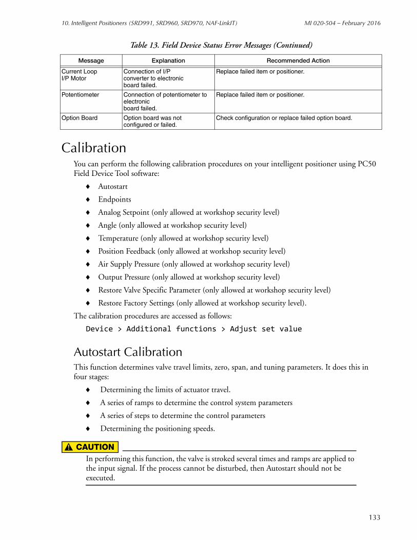
10. Intelligent Positioners (SRD991, SRD960, SRD970, NAF-LinkIT) MI 020-504 – February 2016
CalibrationYou can perform the following calibration procedures on your intelligent positioner using PC50 Field Device Tool software:
Autostart
Endpoints
Analog Setpoint (only allowed at workshop security level)
Angle (only allowed at workshop security level)
Temperature (only allowed at workshop security level)
Position Feedback (only allowed at workshop security level)
Air Supply Pressure (only allowed at workshop security level)
Output Pressure (only allowed at workshop security level)
Restore Valve Specific Parameter (only allowed at workshop security level)
Restore Factory Settings (only allowed at workshop security level).
The calibration procedures are accessed as follows:
Device > Additional functions > Adjust set value
Autostart CalibrationThis function determines valve travel limits, zero, span, and tuning parameters. It does this in four stages:
Determining the limits of actuator travel.
A series of ramps to determine the control system parameters
A series of steps to determine the control parameters
Determining the positioning speeds.
! CAUTIONIn performing this function, the valve is stroked several times and ramps are applied to the input signal. If the process cannot be disturbed, then Autostart should not be executed.
Current LoopI/P Motor
Connection of I/Pconverter to electronicboard failed.
Replace failed item or positioner.
Potentiometer Connection of potentiometer to electronicboard failed.
Replace failed item or positioner.
Option Board Option board was notconfigured or failed.
Check configuration or replace failed option board.
Table 13. Field Device Status Error Messages (Continued)
Message Explanation Recommended Action
133

MI 020-504 – February 2016 10. Intelligent Positioners (SRD991, SRD960, SRD970, NAF-LinkIT)
The procedure to perform an Autostart calibration is:
1. Select Autostart from the Adjust set value menu.
2. Acknowledge the warning.
3. Enter the calibration data or suitable message upon successful completion.
If Autostart is not successful, it may terminate before reaching the last step. This means that the positioner is not properly calibrated. To check whether Autostart has been successfully completed or not, select Valve Status from Test in the device top level menu. Potential reasons for Autostart not completing include:
Positioner mounting problem. Feedback lever or coupling is in the wrong orientation. Refer to Section 1 of MI EVE 0105A on “getting started”.
Inadequate supply pressure.
Large actuator. Use Endpoint Calibration and tune manually. Employ boosters to increase output capacity.
Hardware problem.
Endpoints CalibrationEndpoints calibration automatically detects the valve end points. It does this by using only the first of the four Autostart steps. This process determines the valve mechanical travel stops, zero and span, but not the tuning set. Accordingly, it requires much less time than a full Autostart calibration. If the tuning parameters are available for the control valve from previous testing or existing data, then performing Endpoints calibration and manually entering the tuning set shortens the positioner setup time significantly.
The procedure to perform an Endpoints calibration is:
1. Select Endpoints from the Adjust set value menu.
2. Acknowledge the warning.
3. Enter the calibration data or suitable message upon successful completion.
Analog Setpoint CalibrationAnalog setpoint calibration enables you to calibrate the upper and lower limits of the current input (4 mA and 20 mA) if the positioner is being used in analog mode. Using the positioner in the analog mode requires jumper selection on the printed wiring board. Refer to MI EVE 0105A for the correct jumper location.
! CAUTIONWhen in analog mode, the positioner cannot be connected to a voltage source. To do so causes permanent damage to the instrument.
NOTEThis function is only allowed at workshop security level.
134

10. Intelligent Positioners (SRD991, SRD960, SRD970, NAF-LinkIT) MI 020-504 – February 2016
135
The procedure to perform an Analog Setpoint calibration is:
1. Take the positioner out of the process loop and connect it to a current source.
2. Select Analog Setpoint from the Adjust set value menu.
3. Set input current to 4 mA.
4. Acknowledge by entering this value (4 mA) in the edit box on the display.
5. Set the input current to 20 mA.
6. Acknowledge by entering this value (20 mA) in the edit box on the display.
7. The screen responds with the message that the Analog Setpoint Calibration has finished.
Angle CalibrationAngle calibration is needed whenever the printed wiring board or the potentiometer is replaced. This operation is typically done on the bench and may require special tools and removal of the positioner from the valve. Refer to MI EVE 0105A for more information.
NOTEThis function is only allowed at workshop security level.
The procedure to perform an Angle calibration is:
1. Select Angle from the Adjust set value menu.
2. The feedback lever is rotated to the lower angle value (typically 45° down from horizontal).
3. Acknowledge by entering the lower angle value into the edit box on the display.
4. The feedback lever is rotated to the upper angle value (typically 45° up from horizontal).
5. Acknowledge by entering the upper angle value into the edit box on the display.
6. The screen responds with a message that the Angle Calibration has finished.
Temperature CalibrationTemperature calibration is needed whenever the printed wiring board is replaced. The function calibrates the temperature of the internal electronics module. It is intended to be performed on the bench. A temperature probe and other special tools are required. Refer to MI EVE 0105A for more information.
NOTEThis function is only allowed at workshop security level.
The procedure to perform a Temperature Calibration is:
1. Select Temp from the Adjust set value menu.
2. After selecting Continue to proceed, measure the electronics temperature with a probe.
3. Enter this value in the edit box on the display and select Continue.
The temperature calibration is finished.

MI 020-504 – February 2016 10. Intelligent Positioners (SRD991, SRD960, SRD970, NAF-LinkIT)
Position Feedback CalibrationThis function performs calibration of the output of the position feedback option board. This is typically done on the bench and may require special tools and special electrical connections. This function is accessed by selecting Pos Feedback from the Adjust set value menu. Refer to MI EVE 0105A for more information.
NOTEThis function is only allowed at workshop security level.
Air Supply Pressure CalibrationAir Supply Pressure Calibration is needed whenever the printed wiring board is replaced. This operation is typically done on the bench and may require special tools. Refer to MI EVE 0105A for more information.
NOTEThis function is only allowed at workshop security level.
The procedure to perform an Air Supply Pressure Calibration is:
1. Select Air Supply from the Adjust set value menu.
2. Regulate the air supply to the LOW supply pressure value.
3. Enter this value in the edit box on the display and select Continue.
4. Regulate the air supply to the HIGH supply pressure value.
5. Enter this value in the edit box on the display and select Continue.
The Air Supply Pressure Calibration is finished.
Output Pressure CalibrationOutput Pressure Calibration is needed whenever the printed wiring board is replaced. This operation is typically done on the bench and may require special tools. Refer to MI EVE 0105A for more information.
NOTEThis function is only allowed at workshop security level.
The procedure to perform an output pressure calibration is:
1. Select Output Pressure from the Adjust set value menu.
2. Using the pushbuttons, set the setpoint to 0%.
3. Check the pressure gauge attached to the output port of the positioner. Enter this value in the edit box on the display and select Continue.
4. Using the pushbuttons, set the setpoint to 100%.
5. Check the pressure gauge attached to the output port of the positioner. Enter this value in the edit box on the display and select Continue.
The Output Pressure Calibration is finished.
136
10. Intelligent Positioners (SRD991, SRD960, SRD970, NAF-LinkIT) MI 020-504 – February 2016
Restore Valve-Specific ParameterThis function allows writing of valve specific parameters into the positioner. By reading the data file of one positioner mounted to a valve and writing these values into a new positioner, the new positioner is adopted to that valve without performing an Autostart Calibration. However, due to mechanical tolerances in mounting, the adoption is not optimal. Therefore, performing a new Autostart Calibration or Endpoint Calibration is required as soon as possible. This function is accessed by selecting Restore Valve-Specific Parameter from the Adjust set value menu.
NOTEThis function is only allowed at workshop security level.
Restore Factory SettingsThis function resets all calibration and configuration data back to the calibration and configuration data existing at time of delivery from the factory. The valve’s current database is overwritten. This function is useful, for example, when a positioner is taken from one valve and mounted to another valve. This function is accessed by selecting Restore Factory from the Adjust set value menu.
NOTEThis function is only allowed at workshop security level.
Mode ChangeYou can perform the following mode changes on the positioners: On-Line, Off-line, Local Mode, Factory, and Calibrate. Use the following path to access this function:
Device > Additional functions > Commands > Mode Change
On-LineThis function sets the device into the on-line mode where normal control is performed. The positioner allows a digital or analog setpoint depending on the configuration of the set-point source.
Off-LineThis function sets the device into the off-line mode where normal control is not performed. The pneumatic output is frozen to the last value of the pneumatic output before performing this function.
Local ModeThis function sets the device into the local mode. Local mode is similar to on-line mode where normal control is performed. However, the positioner does not follow the digital or analog setpoint from the I/A Series system. It follows the digital setpoint from the Field Device Tool.
137

MI 020-504 – February 2016 10. Intelligent Positioners (SRD991, SRD960, SRD970, NAF-LinkIT)
CalibrateThis function sets the device into calibrate mode.
FactoryThis function is for use by Global Customer Support personnel only.
Reset StatusThis function resets all current and historical status fields including the Diagnostic Status fields. It is accessed via the following path:
Device > Additional functions > Commands > Reset Status
NOTEIf an underlying problem has not been corrected, the failure bits will be reasserted almost immediately.
Reset CountersThis function resets the Cycle Count and Travel Sum parameters. his causes the device to be taken off-line for a short period which can cause a process upset. It is accessed via the following path:
Device > Additional functions > Commands > Reset Counters
Reset DeviceThis function causes the positioner to be rebooted. It is accessed via the following path:
Device > Additional functions > Commands > Reset Device
! CAUTIONThe device behaves as if the power supply were switched off and on. This can cause a process upset.
Write ProtectThis function enables or disables write protection for valve parameters. If Write Protect is enabled, the positioner is write protected and inadvertent changing of positioner configuration data is prevented. This function is accessed via the following path:
Device > Additional functions > Commands > Write Protect
138

10. Intelligent Positioners (SRD991, SRD960, SRD970, NAF-LinkIT) MI 020-504 – February 2016
Configuration
Identifier Tab Screen
Figure 88. Sample SRD991 Identifier Tab Screen
Field Entry
Tag Number Enter maximum of 12 characters. The first 8 characters become the positioner configuration filename.
Tag Name Enter maximum of 14 characters. Optional, used for reference only.
Device Name Enter maximum of 6 characters.NOTE: To disable enhanced protocol name checking with I/A Series Versions 3.0 or later, enter DevNam.
Location Enter maximum of 14 characters. Optional, used for reference only.
139

MI 020-504 – February 2016 10. Intelligent Positioners (SRD991, SRD960, SRD970, NAF-LinkIT)
Parameters Tab Screen
Figure 89. Sample SRD991 Parameters Tab Screen
Field Entry
Messages 1, 2, and 3 Enter up to three messages, each up to 14 characters long.
Model Code
Instrument Displays the factory entered positioner model code.
Information
Calibration Enter calibration info message (14 characters maximum).
Maintenance Enter maintenance message (14 characters maximum).
Fab. Number Displays a factory entered identification number.
HW Rev. Displays the factory entered hardware revision level.
Serial Number
Actuator Enter actuator serial number.
Valve Enter valve serial number.
140
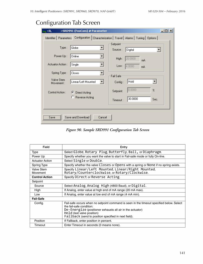
10. Intelligent Positioners (SRD991, SRD960, SRD970, NAF-LinkIT) MI 020-504 – February 2016
Configuration Tab Screen
Figure 90. Sample SRD991 Configuration Tab Screen
Field Entry
Type Select Globe, Rotary Plug, Butterfly, Ball, or Diaphragm.
Power Up Specify whether you want the valve to start in Fail-safe mode or fully On-line.
Actuator Action Select Single or Double.Spring Type Specify whether the valve Closes or Opens with a spring or None if no spring exists.
Valve StemMovement
Specify Linear/Left Mounted, Linear/Right Mounted, Rotary/Counterclockwise, or Rotary/Clockwise.
Control Action Specify Direct or Reverse Acting.
Setpoint
Source Select Analog, Analog High (4800 Baud), or Digital.High If Analog, enter value at high end of mA range (20 mA max).
Low If Analog, enter value at low end of mA range (4 mA min).
Fail-SafeConfig. Fail-safe occurs when no setpoint command is seen in the timeout specified below. Select
the fail-safe condition:De-Energize (positioner exhausts all air in the actuator)Hold (last valve position)Fallback (send to position specified in next field).
Position If Fallback, enter position in percent.Timeout Enter Timeout in seconds (0 means none).
141
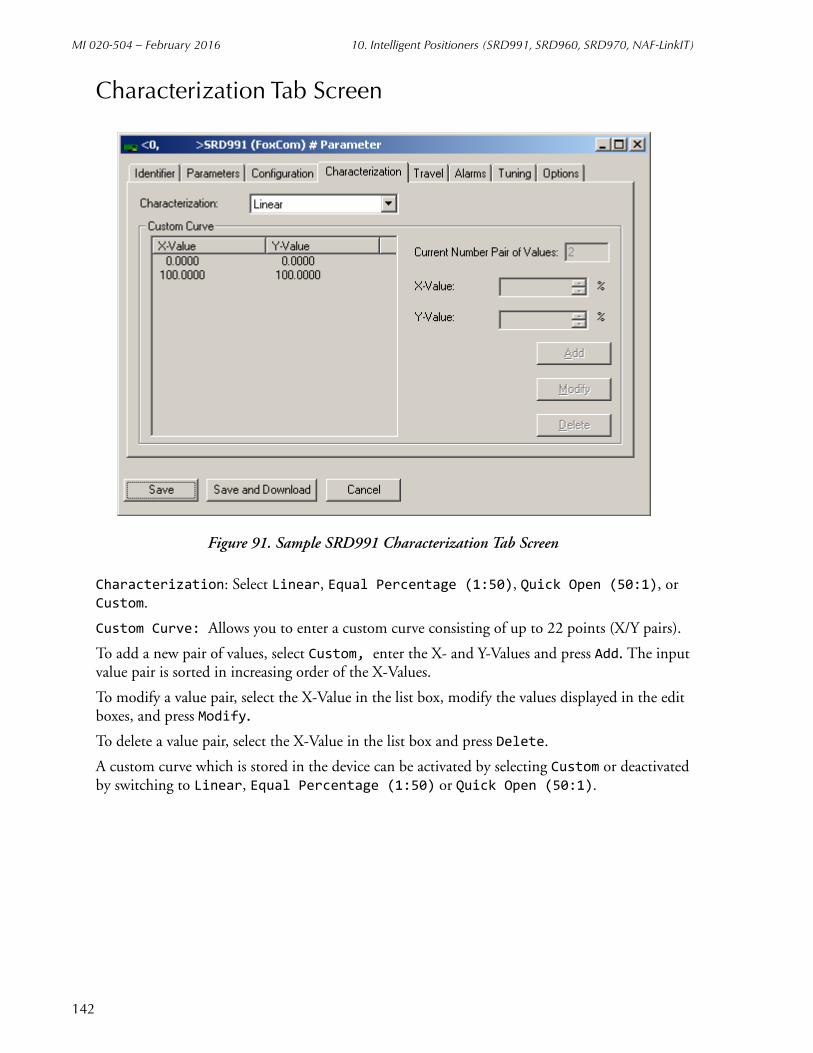
MI 020-504 – February 2016 10. Intelligent Positioners (SRD991, SRD960, SRD970, NAF-LinkIT)
Characterization Tab Screen
Figure 91. Sample SRD991 Characterization Tab Screen
Characterization: Select Linear, Equal Percentage (1:50), Quick Open (50:1), or Custom.
Custom Curve: Allows you to enter a custom curve consisting of up to 22 points (X/Y pairs).
To add a new pair of values, select Custom, enter the X- and Y-Values and press Add. The input value pair is sorted in increasing order of the X-Values.
To modify a value pair, select the X-Value in the list box, modify the values displayed in the edit boxes, and press Modify.
To delete a value pair, select the X-Value in the list box and press Delete.
A custom curve which is stored in the device can be activated by selecting Custom or deactivated by switching to Linear, Equal Percentage (1:50) or Quick Open (50:1).
142

10. Intelligent Positioners (SRD991, SRD960, SRD970, NAF-LinkIT) MI 020-504 – February 2016
Travel Tab Screen
Figure 92. Sample SRD991 Travel Tab Screen
Field Entry
Response Time [Limit]
Measured T63 Time 0-100%
Displays the time it took for the valve to travel 63% of its full stroke in the increasing direction during Autostart.
Measured T63 Time 100-0%
Displays the time it took for the valve to travel 63% of its full stroke in the decreasing direction during Autostart.
Cutoff
Cutoff Deadband Enter the amount of hysteresis in percent of travel required above the cutoff value before the valve can reopen again. For example, with 2% cutoff, 0.5% cutoff hysteresis allows the valve to reopen at 2.5%.
Cutoff % Enter the value in percent of travel below which the valve is fully closed. For example, when set at 2%, any signal below 2% is treated as 0%.
Cutoff 100% Enter the value in percent of travel above which the valve is fully open.
Travel Stops
Lower Enter lower travel stop in percent of total stroke.
Upper Enter upper travel stop in percent of total stroke.
Travel Position Units Select mm, Inches, or Degrees
Stroke Enter the stroke in the units specified.
143
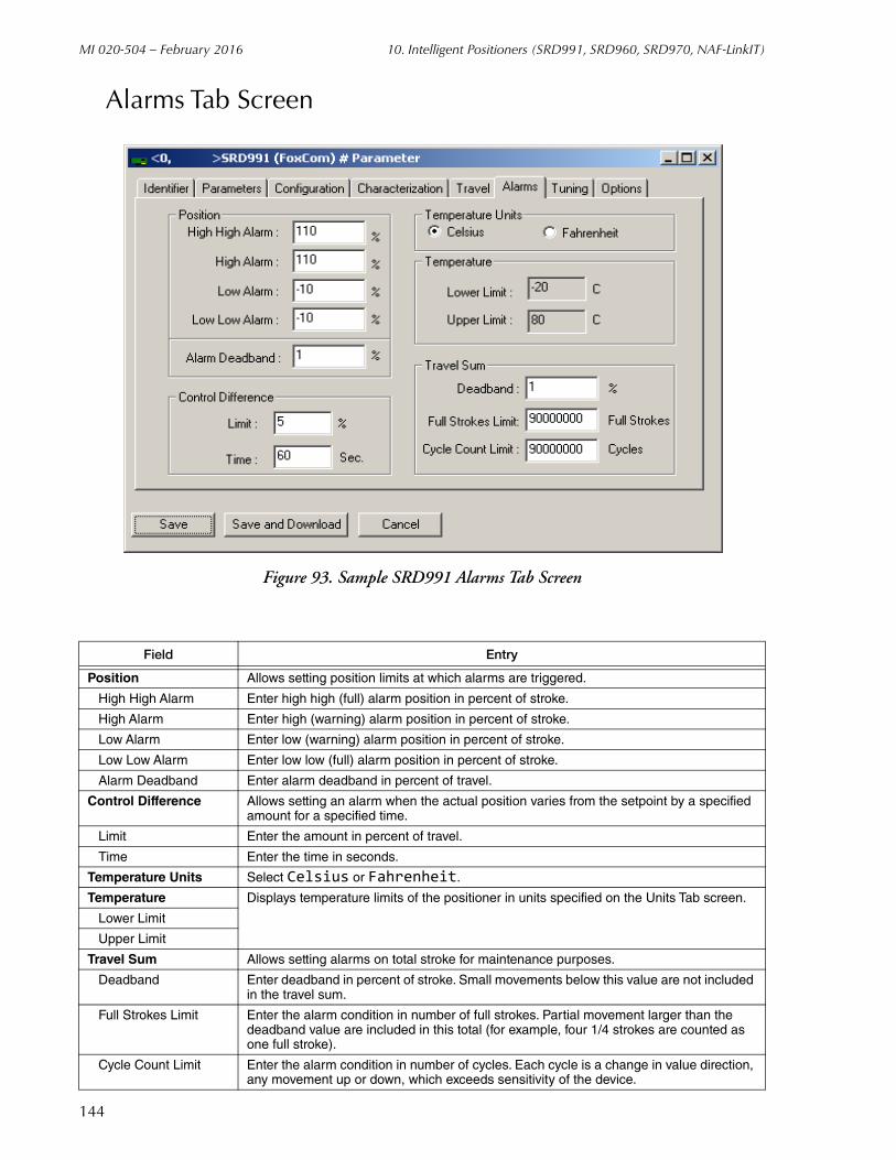
MI 020-504 – February 2016 10. Intelligent Positioners (SRD991, SRD960, SRD970, NAF-LinkIT)
144
Alarms Tab Screen
Figure 93. Sample SRD991 Alarms Tab Screen
Field Entry
Position Allows setting position limits at which alarms are triggered.
High High Alarm Enter high high (full) alarm position in percent of stroke.
High Alarm Enter high (warning) alarm position in percent of stroke.
Low Alarm Enter low (warning) alarm position in percent of stroke.
Low Low Alarm Enter low low (full) alarm position in percent of stroke.
Alarm Deadband Enter alarm deadband in percent of travel.
Control Difference Allows setting an alarm when the actual position varies from the setpoint by a specified amount for a specified time.
Limit Enter the amount in percent of travel.
Time Enter the time in seconds.
Temperature Units Select Celsius or Fahrenheit.
Temperature Displays temperature limits of the positioner in units specified on the Units Tab screen.
Lower Limit
Upper Limit
Travel Sum Allows setting alarms on total stroke for maintenance purposes.
Deadband Enter deadband in percent of stroke. Small movements below this value are not included in the travel sum.
Full Strokes Limit Enter the alarm condition in number of full strokes. Partial movement larger than the deadband value are included in this total (for example, four 1/4 strokes are counted as one full stroke).
Cycle Count Limit Enter the alarm condition in number of cycles. Each cycle is a change in value direction, any movement up or down, which exceeds sensitivity of the device.

10. Intelligent Positioners (SRD991, SRD960, SRD970, NAF-LinkIT) MI 020-504 – February 2016
Tuning Tab Screen
Figure 94. Sample SRD991 Tuning Tab Screen
Field Entry
Increasing Position
Proportional Enter proportional gain value.
Integral Enter reset time in seconds.
Derivative Enter derivative time in seconds.
Decreasing Position
Proportional Enter proportional gain value.
Integral Enter reset time in seconds.
Derivative Enter derivative time in seconds.
Travel Time Limits
Increasing Entering values higher than the defaults slows down response. Travel time limits are used to modify control valve dynamics.Decreasing
Control Gap Control gap defines the sensitivity of the positioner so that no corrective action is taken if the control difference is less than the defined limit.
145
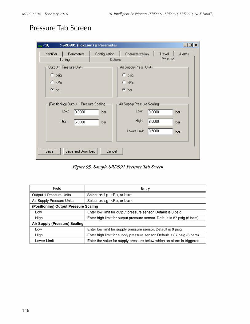
MI 020-504 – February 2016 10. Intelligent Positioners (SRD991, SRD960, SRD970, NAF-LinkIT)
Pressure Tab Screen
Figure 95. Sample SRD991 Pressure Tab Screen
Field Entry
Output 1 Pressure Units Select psig, kPa, or bar.
Air Supply Pressure Units Select psig, kPa, or bar.
(Positioning) Output Pressure Scaling
Low Enter low limit for output pressure sensor. Default is 0 psig.
High Enter high limit for output pressure sensor. Default is 87 psig (6 bars).
Air Supply (Pressure) Scaling
Low Enter low limit for supply pressure sensor. Default is 0 psig.
High Enter high limit for supply pressure sensor. Default is 87 psig (6 bars).
Lower Limit Enter the value for supply pressure below which an alarm is triggered.
146

10. Intelligent Positioners (SRD991, SRD960, SRD970, NAF-LinkIT) MI 020-504 – February 2016
Options Tab Screen
Figure 96. Sample SRD991 Options Tab Screen
Field Entry
Option Board Select from the following:No External OptionExternal Position TransmissionExternal Binary InputExternal Binary OutputExternal Analog Sensor
Internal Pressure Sensors Select or deselect internal pressure sensors.
147

MI 020-504 – February 2016 10. Intelligent Positioners (SRD991, SRD960, SRD970, NAF-LinkIT)
Bin In Tab Screen
Figure 97. Sample SRD991 Bin In Tab Screen
The Binary Input option features two independent binary inputs with internal supply for connection of sensors. A connected switch is loaded with 3.5 V and 0.15 mA.
Using the Bin In Tab screen, you can configure an active signal to activate an alarm or force the actuator to go to 0% or 100%.
148
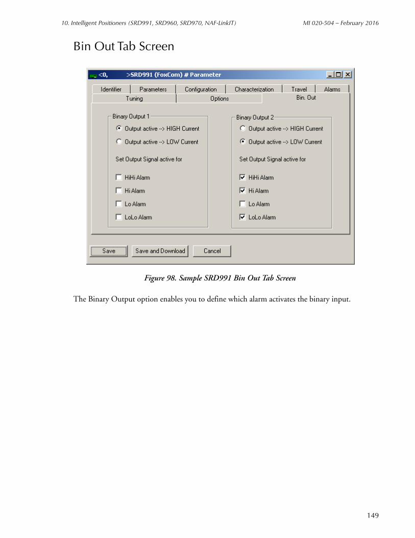
10. Intelligent Positioners (SRD991, SRD960, SRD970, NAF-LinkIT) MI 020-504 – February 2016
Bin Out Tab Screen
Figure 98. Sample SRD991 Bin Out Tab Screen
The Binary Output option enables you to define which alarm activates the binary input.
149

MI 020-504 – February 2016 10. Intelligent Positioners (SRD991, SRD960, SRD970, NAF-LinkIT)
150
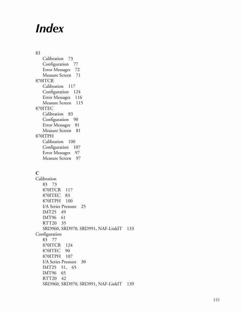
Index
83Calibration 73Configuration 77Error Messages 72Measure Screen 71
870ITCRCalibration 117Configuration 124Error Messages 116Measure Screen 115
870ITECCalibration 83Configuration 90Error Messages 81Measure Screen 81
870ITPHCalibration 100Configuration 107Error Messages 97Measure Screen 97
CCalibration
83 73870ITCR 117870ITEC 83870ITPH 100I/A Series Pressure 25IMT25 49IMT96 61RTT20 35SRD960, SRD970, SRD991, NAF-LinkIT 133
Configuration83 77870ITCR 124870ITEC 90870ITPH 107I/A Series Pressure 30IMT25 51, 65IMT96 65RTT20 42SRD960, SRD970, SRD991, NAF-LinkIT 139
151

MI 020-504 – February 2016 Index
DDiagnosis 17
EError Messages
83 72870ITCR 116870ITEC 81870ITPH 97I/A Series Pressure 24IMT25 47IMT96 60RTT20 34SRD960, SRD970, SRD991, NAF-LinkIT 132
II/A Series Pressure
Calibration 25Configuration 30Error Messages 24Measure Screen 23
IMT25Calibration 49Configuration 51, 65Error Messages 47Measure Screen 47
IMT96Calibration 61Configuration 65Error Messages 60Measure Screen 59
MMeasure Screen
83 71870ITCR 115870ITEC 81870ITPH 97I/A Series Pressure 23IMT25 47IMT96 59RTT20 33SRD960, SRD970, SRD991, NAF-LinkIT 131
Mode Change 21
152
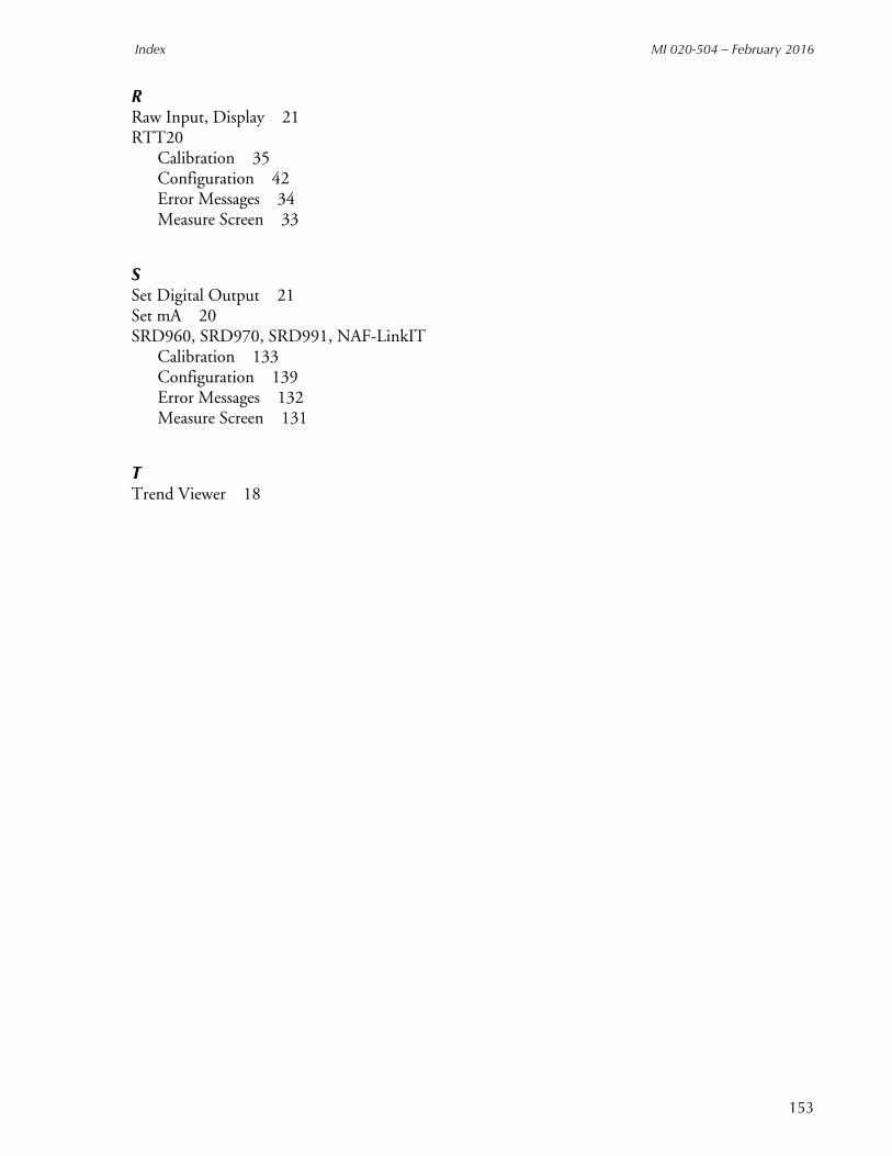
Index MI 020-504 – February 2016
RRaw Input, Display 21RTT20
Calibration 35Configuration 42Error Messages 34Measure Screen 33
SSet Digital Output 21Set mA 20SRD960, SRD970, SRD991, NAF-LinkIT
Calibration 133Configuration 139Error Messages 132Measure Screen 131
TTrend Viewer 18
153

MI 020-504 – February 2016
ISSUE DATESOCT 2003SEP 2007AUG 2009FEB 2016
Vertical lines to the right of text or illustrations indicate areas changed at last issue date.
Invensys Systems, Inc.38 Neponset AvenueFoxboro, MA 02035United States of Americahttp://www.fielddevices.foxboro.com
Global Customer SupportInside U.S.: 1-866-746-6477Outside U.S.: 1-508-549-2424Website: http://support.ips.invensys.com
Copyright 2003-2016 Invensys Systems, Inc.All rights reserved.
Invensys, Foxboro, and I/A Series are trademarks of Invensys Limited, its subsidiaries, and affiliates. All other trademarks are the property of their respective owners.
Invensys is now part of Schneider Electric.
0216


