47 Airport Road WINNIPEG, Manitoba CANADA R3H 0V5 Toll Free: 1 - 800- 665 - 8089 Ph#: 204 - 779 - 7791 Fax#: 204 - 779- 7796 Email: sales@empire - machinery.com Web: www.empire - machinery.com Imported By: Instruction & Parts Manual for CMZ - 7R Power Rotary Machine Operator must read and understand Instruction Manual prior to operating the CMZ -7R Power Rotary Machine, as damage to machine or personal inj ury may result. Electrician must refer to electrical schematics in this manual before initial startup.
Electrician must refer to electrical schematics in this manual before initial startup.
ROTARY MACHINE SAFETY RULES
CMZ-7R machine should be DISCONNECTED from power source
before servicing.
Never place any part of the body including loose clothing near or
onto the rotating rolls. (KEEP HANDS AWAY). Failure to follow
this procedure will lead to personal body injury.
Never clean forming rolls while they are rotating.
Do not exceed specified material capacity of the machine.
Machine must be operated by authorized personal who have been
trained in regards to working and safety features of the machine.
Please read and understand the Operators Manual.
Never operate machine with any guards removed.
Do not use machine if service is required.
Use safety glasses and required protective equipment.
Keep work areas clean and in proper order.
START UP/OPERATION INSTRUCTIONS
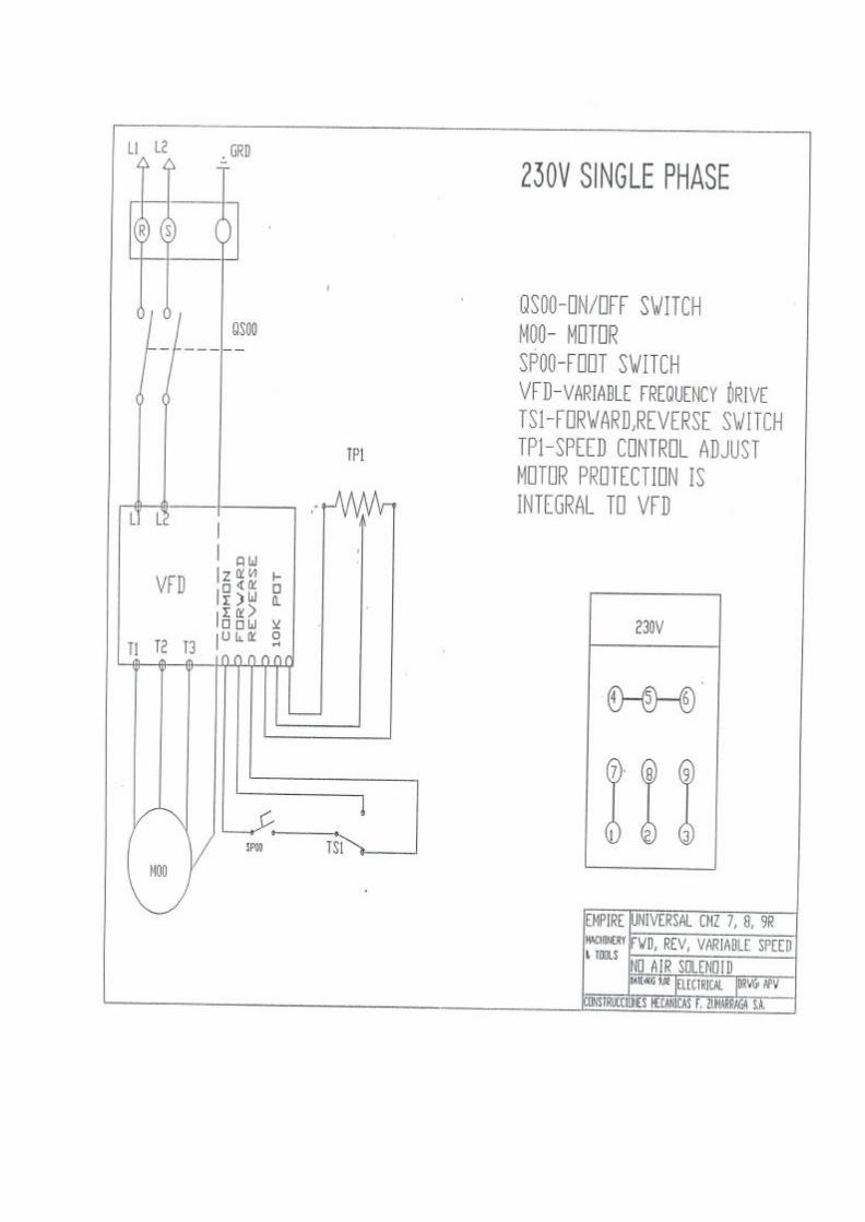
WIRING Prior to electrical hookup please refer to Wiring Schematic on next page. CLEANING Remove the factory applied rust inhibitor with a degreasing agent or oil soaked rags. LUBRICATION Check gearbox Oil Sight Glass (2) for proper oil levels The following tables will provide you with manufacturers and types of oil and grease recommended by the factory. Lubricate all points as marked with the proper grease using the fitting included in this information package.
US GREASE & OIL SPECIFICATIONS CANADIAN GREASE & OIL SPECIFICATIONS
BRAND GREASE OIL
US Mobil Brand Mobilux Grease 2 Mobil DTE 24
Shell OilUS Product Info#1-800-231-6950
Alvania EP2Alvania
Gerase 2 Shell Tellus 32
Esso Lonax/Lidok EP2 Nuto H32
BRAND GREASE OIL
Nemco Available in: Winnipeg, Regina,
Saskatoon
LCEP2 Hydrol AW32
Shell Canada Alvania EP2Alvania
Grease 2 Shell Tellus 32
Esso Lonax/Lidok EP2 Nuto H32
ELECTRICAL INSTALLATION CMZ-7R Power Rotary Machine Must Be Installed By a Certified Electrician Please see wiring schematics for proper location to run your power lines to. (FAILURE TO WIRE ACCORDING TO WIRING SCHEMATICS WILL RESUT IN INVERTER DAMAGE) ROLL INSTALLATION The CMZ-7R comes with a lower shaft adjustment (14) so rolls with differing centerlines can be lined up. Loosen the locking screw on the right hand side of the unit (12) and then bring the rolls together. Once the rolls have fit snugly together firmly lock the shaft in place. THROAT GAUGE ADJUSTMENT The CMZ-7R is fitted with adjustable Throat Gauge Guides. For operation of machine where limited throat gauge depth is required the guides should be located to the front of the of the shafts. Where deeper operations are required the Throat Gauge Guides must be removed and placed in their proper locations near the back of the shafts. DEPTH CONTROL The CMZ-7R comes standard with a manual screw adjustment for control of the upper shaft depth. (9). If you look directly behind the Adjusting Screw you will see the Upper Shaft Tensioning Screw (10). This is factory set and should never need adjustment. ROLL INSTALLATION Rolls must be secured by means of the Roll Locking Nuts (5) provided. Upper Roll Lock Nut is Left Hand Thread and the Lower Roll Lock Nut is Right Hand Thread. Failure to secure rolls will result in roll and shaft damage and will void all factory warranties. CMZ-7R comes with a set of 3/8” Single Bead Rolls as standard. (We will quote on any roll application you may require) SPEED CONTROL Your CMZ-7R is equipped with a Speed Control and Forward/Reverse Switch. Forward/Off/Reverse Switch must be in either Forward or Reverse position to operate. Machine will only run if foot pedal is depressed. Operator should never switch between forward and reverse while the rolls are turning as damage may occur. Speed may be adjusted while rolls are turning.
Optional Accessories for CMZ-7R and CMZ-9R:
• Single Bead Rolls (3/16”, 1/4”, 1/2”)
• HEAVY Crimping Rolls (1-1/2”) 16GA/18GA
• HEAVY Combination Crimp & 3/8” Bead Rolls (Inc. Spacer to allow use of crimp rolls only)
• NEW! LIGHT Crimping Rolls (20GA & lighter)
• LIGHT Combination Crimp & 3/8” Bead Rolls (Inc. Spacer to allow use of crimp rolls only)
(Raises & Lower Top Shaft with Foot Switch (Not to Be Used with #20 Flange Rolls or Spin In Rolls)
• Air Over Oil Hydraulic Cylinder (Foot Pedal Controlled)Top Shaft Control
• Digital Programmable Top Shaft Control
• Spring Loaded Pipe Support Stand
• Larger Front Face Plate c/w Internal Bearing Supports
Optional Air Cylinder Op-tion Allows for Hands
Free Operation
Hardened Steel Back-ing Plate
Optional Base Raises the Standard Working Height
from 33” to 38”
Optional Speed Control gives operator infinitely variable speed and forward/reverse at the flip of
a switch
High Efficiency Motor Dual Voltage Motor
Safety Covered Footswitch
11” Throat Depth
Bead 1/8”, 3/16”, 1/4”,
3/8”, 1/2”
Offset
Slit
Crimp or Combination
Bead & Crimp
1/4” or 1/2” 90` Flange Rolls (Pipe Stays in Horizontal Position) Power Rotary Machine
Offset Rolls With large spacers on the top and bottom shafts install the male offset roll on the top shaft and the female offset roll on the bottom shaft Tighten locking collars. Bring top shaft down until rolls are just touching. Loosen locking screw on the bottom shaft and adjust the bottom roll until there is about 2 times material thickness between the male and female portion of the rolls. Adjust the backstop up to the back of the bottom roll so it is almost touching the roll but not rubbing and lock in place. Place material onto the bottom roll and up against the backstop. Start the rolls turning and bring the top shaft down and form the offset. You may be required to do some minor adjustments to the spacing for optimum parts.
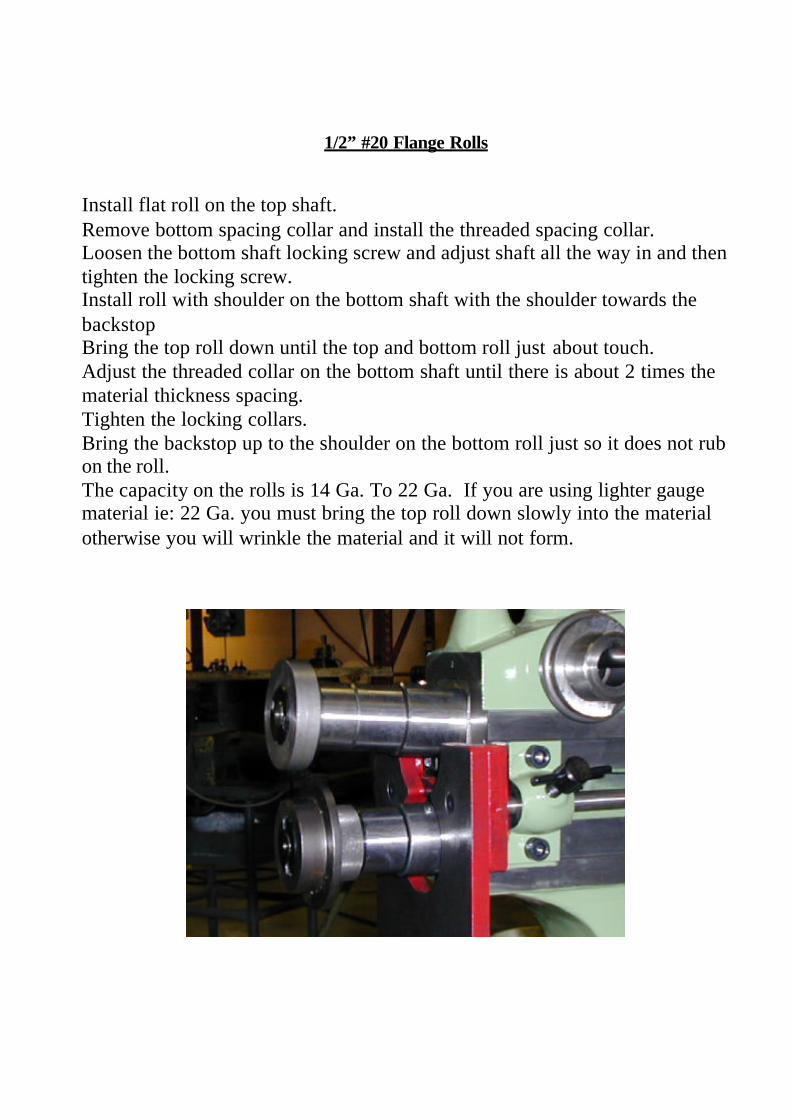
1/2” #20 Flange Rolls Install flat roll on the top shaft. Remove bottom spacing collar and install the threaded spacing collar. Loosen the bottom shaft locking screw and adjust shaft all the way in and then tighten the locking screw. Install roll with shoulder on the bottom shaft with the shoulder towards the backstop Bring the top roll down until the top and bottom roll just about touch. Adjust the threaded collar on the bottom shaft until there is about 2 times the material thickness spacing. Tighten the locking collars. Bring the backstop up to the shoulder on the bottom roll just so it does not rub on the roll. The capacity on the rolls is 14 Ga. To 22 Ga. If you are using lighter gauge material ie: 22 Ga. you must bring the top roll down slowly into the material otherwise you will wrinkle the material and it will not form.
Crimp Rolls Remove the large shaft spacing collars on the top and bottom shaft Install the small spacers that came with the rolls on the shafts . Install the top and bottom crimp roll with the recess in the face of the roll to the front of the machine. Bring the top shaft down until the rolls mesh together. Tighten the locking collars. Adjust the backstop up to the end of the crimp rolls and tighten. When you are ready to form the crimp. With the rolls separated place your material over the bottom roll until the material is against the backstop. DO NOT START THE MACHINE UNTIL YOU BRING THE TOP ROLL DOWN AND TIGHTEN FIRMLY TOGETHER SANDWICHING THE MATERIAL BETWEEN THE ROLLS. You can now press on the footswitch and begin the crimping process.
Combination Bead & Crimp Remove the large shaft spacing collars on the top and bottom shaft Install the top and bottom crimp rolls with the recess in the face of the roll to the back of the shaft. Install the male bead roll on the bottom shaft with the highest portion of the roll facing out. Install the female bead roll on the top shaft with the highest portion of the roll facing out. Bring the top shaft down until the rolls mesh together. Tighten the locking collars. Adjust the backstop up to the end of the crimp rolls and tighten. When you are ready to form the crimp. With the rolls separated place your material over the bottom roll until the material is against the backstop. DO NOT START THE MACHINE UNTIL YOU BRING THE TOP ROLL DOWN AND TIGHTEN FIRMLY TOGETHER SANDWICHING THE MATERIAL BETWEEN THE ROLLS. You can now press on the footswitch and begin the crimping process.
CMZ-7R Air Cylinder Operation
The CMZ-7R Air Cylinder option is a cost effective way of allowing the operator hands free operation to maintain full control of the part being formed. This option is not recommended for Flanging Rolls or Spin In Collar Rolls as these rolls require a stepping down of the top shaft and the travel on the air cylinder is continuous and not able to stop & start during the forming process which is a requirement for these rolls. The air cylinder is initialized when the foot pedal is depressed and returns to its home position when the foot pedal is released. The air cylinder option comes standard with a closing speed adjustment valve which is used to control the speed of the top shaft coming together to pinch the material. Also included is a depth stop adjustment which allows the operator to stop the top shaft at a predetermined depth for production operations. If for any reason the air cylinder must be removed to allow the operator to utilize the standard hand crank that was shipped with your CMZ-7R the following process must be followed. First disconnect the air supply from your compressor to the unit. Then remove the plastic air line from the top of the air cylinder that is connected to the end of the speed control valve by pushing and holding the plastic ring in while pulling on the air line. Next loosen the jam nut (shown in the picture above) and then spin the air cylinder out of the threaded hole and thread in the hand crank.
Air Cylinder Closing Speed Adjustment
Depth Stop Adjustment
Jam Nut
CMZ-7R Programmable Top Shaft Control
The PLC Control for the top shaft on the CMZ-7R is a single program control that utilizes intervals of air being introduced to the air over oil hydraulic system and wait times between each burst of air. The control has three different operating modes and they are explained as follows: MANUAL: In manual mode the top shaft is controlled by means of either pushing the UP or DOWN buttons on the keypad. Very few of the other buttons on the keypad will function when in manual mode. AUTOMATIC: In automatic mode all the function buttons on the keypad are useable. After a program is entered and the home position is set then the foot pedal is activated and must remain activated until the end of the program. If the foot pedal is released before the end of the program then the top shaft will return to it home position and will begin at the start of the program. SEMI AUTOMATIC: In semi automatic mode the functions are the same as in automatic mode but the only difference is if the foot pedal is released during the cycle it will remain in that position and then the top shaft can be repositioned by means of the up and down buttons on the keypad. PROGRAMMING THE CONTROL: Each part may vary and must be programmed with this in mind. Some parts require a full revolution before the top shaft can be fed down i.e. Spin-In Collar and ½” Flange Rolls. With this in mind you will need to vary your speed of the rolls to match the settings on the control. This can only be done with a little bit of trial and error. There are three different settings that make up a program and they are as follows:
INDEX TIME: This is the amount of time that air will be introduced to the system thereby driving the top shaft down with each burst of air. The shorter the time the larger the number of steps will be required to get to the bottom of the stroke. NOTE: There is less than 1” of stroke required to get from the top of the stroke to the bottom. The number should never have to be much longer than ½ a second for a simple part like a bead of a fraction of a second for the spin collar rolls. WAIT TIME: This is the amount of time required between the bursts of air. This number will be set according to the diameter of part and if the part requires a full revolution or not before the next downward movement of the top shaft.
INDEX #: This number is the number of downward movements of the top shaft is required to complete the program and the part. Once the control has counted this number of movements you will be instructed to release the foot pedal. This number is also a trial and error number that must be set by trying a part to determine the required movements of the top shaft to finish the part. NOTE: This number may need to be adjusted if you set the program without running material for purposes of setup. The ARROW KEYS are used to navigate between each setting and the CLR button clears the existing numbers. Using the numbers on the pad enter the required setting and then press ENTER. NOTE: If ENTER is not pressed after each change the number will not be accepted.
HOME: This button returns the top shaft to a preset home position no matter what mode or position the top shaft is in. LEARN HOME: This button teaches the control the home position. Extra care must be taken when entering the values in this area, as severe damage will occur to the machine as over travel may occur if too large a value is entered. To program the home position press the LEARN HOME button on the keypad. Doing this will take you into a different screen, there will be three different settings that can be changed on this screen and they are explained as follows: RISE TIME: This value is the time that the control allows for the top shaft to rise after the program is finished or the HOME button is pushed. WAIT TIME: This value is the wait time allowed after the top shaft reaches the top of stroke. This value is important as some different roll profiles may take more time than others to remove the part from the rolls. DOWN TIME: This value is the time allowed for the top shaft to return to its home position. Careful attention must be made when entering this value as damage to the machine will occur if too long a value is place here. You should never have a value much longer that 3 seconds. To program a new home position press LEARN HOME and then use the arrow buttons to move between the settings. Use the CLR button to clear each value and enter the new value. Remember to press ENTER after each change. Once you have made all the necessary changes you must press LEARN HOME to finish the teach function. You will now be back at the program screen and ready to run parts. To test your new home position press the HOME button. REMEMBER THE EMERGENCY BUTTON SHUTS DOWN ALL THE FUNCTIONS ON THE MACHINE. IF YOU SENSE THAT SOMETHING IS NOT RIGHT PRESS THE RED EMERGENCY LOCATED ON THE PANEL ABOVE THE KEYPAD.
Air/Oil Hydraulic with Foot Pedal Control
The Air/Oil with foot pedal control uses the same feed system as the programmable
control for the top shaft but the difference in the way it is actuated is by means of a two
position foot pedal allowing hands free operation of the CMZ-7R. There are two separate
micro switches in the foot pedal and they operate as follows. When you press on the
pedal halfway down the rolls begin to turn and then by pressing the pedal all the way to
the floor you then activate the air/hydraulic system causing the top shaft to start traveling
down.(CAUTION IF THE OPERATOR HOLDS THE PEDAL TOO LONG
AFTER THE ROLLS COME TOGETHER DAMAGE TO THE MACHINE AND
OR THE OPERATOR WILL OCCUR). To jog the top shaft down and then hold it at
a desired position just bring the pedal back to the halfway point and keep your foot there
and the top shaft will stop coming down and hold in the position. To continue stepping
down the top shaft you can lightly tap your foot to the floor and bring it back to the center
position until the desired profile is achieved. Once your part is finished raise your foot
completely off the foot pedal and the top shaft will return to its home position and the
rolls will stop rotating. For repetitive parts where a certain depth is required for each part
the yellow stop nut on the top of the hydraulic cylinder can be turned up or down and can
be used as an indicator to the operator that the desired depth has been reached.
Electrical Schematics for Air/Oil Hydraulic Package