41
S1000 ™ Thermal Cycler Instruction Manual Catalog #184-2000 #185-2196 #185-2197 #185-2148 #185-2138
S1000™ Thermal CyclerInstruction Manual
Catalog #184-2000 #185-2196 #185-2197 #185-2148 #185-2138
S1000 Thermal Cycler Manual
Copyright ©2009 Bio-Rad Laboratories, Inc. Reproduction in any form, either print or electronic, is prohibited without written permission of Bio-Rad Laboratories, Inc.
Windows XP and Windows Vista are trademarks of Microsoft Corporation.
LICENSE NOTICE TO PURCHASER
This base unit, Serial No. ____________, in combination with its immediately attached Bio-Rad sample block module(s), constitutes a thermal cycler whose purchase conveys a limited non-transferable immunity from suit for the purchaser’s own internal research and development and for use in human in vitro diagnostics and all other applied fields under U.S. Patent No. 5,475,610 (claims 1, 44, 158, 160-163 and 167 only) or corresponding claims in their non-U.S. counterparts, owned by Applera Corporation. No right is conveyed expressly, by implication, or by estoppel under any other patent claim, such as claims to apparatus, reagents, kits, or methods such as 5´ nuclease methods. Further information on purchasing licenses may be obtained by contacting the Director of Licensing, Applied Biosystems, 850 Lincoln Centre Drive, Foster City, California 94404, USA.
Bio-Rad’s thermal cyclers and real-time thermal cyclers are covered by one or more of the following U.S. patents or their foreign counterparts owned by Eppendorf AG: U.S. Patent Nos. 6,767,512 and 7,074,367.
Hard-Shell PCR plates are covered by one or more of the following U.S. patents or their foreign counterparts owned by Eppendorf AG: U.S. Patent Nos. 7,347,977, 6,340,589, 6,528,302.
i
S1000 Thermal Cycler Manual
Bio-Rad Laboratories ResourcesTable 1 lists Bio-Rad resources and how to locate what you need.
WarrantyThe S1000 thermal cycler and associated accessories are covered by a standard Bio-Rad warranty. Contact your local Bio-Rad Laboratories office for details of the warranty.
Safety and Regulatory ComplianceThe S1000 thermal cycler heats and cools very quickly during operation. We strongly recommend that you follow the safety specifications listed in this section and throughout this manual.
Use only Bio-Rad USB cable (catalog #184-8000) when using any 1000-series cycler.
Table 1. Bio-Rad resources
Resource How to Contact
Local Bio-Rad Laboratories representatives
Find local information and contacts on the Bio-Rad Laboratories website by selecting your country on the home page (www.bio-rad.com). Find the nearest international office listed on the back of this manual
Technical notes and literature Find technical information on the Bio-Rad Laboratories website (www.bio-rad.com). Type a term in the Search box and select Literature to find links to technical notes, manuals, and other literature
Technical specialists Bio-Rad Laboratories provides quality technical support. We staff our Technical Support department with experienced scientists to provide our customers with practical and expert solutions
To find local technical support on the phone, contact your nearest Bio-Rad Laboratories office. For technical support in the United States and Canada, call 1-800-424-6723 (toll-free phone) and select the technical support option
ii
S1000 Thermal Cycler Manual
r
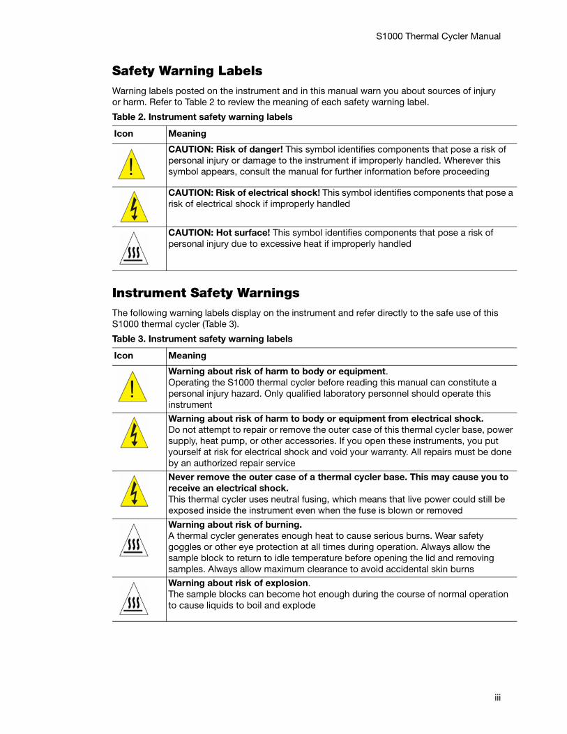
Safety Warning LabelsWarning labels posted on the instrument and in this manual warn you about sources of injury or harm. Refer to Table 2 to review the meaning of each safety warning label.
Instrument Safety WarningsThe following warning labels display on the instrument and refer directly to the safe use of this S1000 thermal cycler (Table 3).
Table 2. Instrument safety warning labels
Icon Meaning
CAUTION: Risk of danger! This symbol identifies components that pose a risk of personal injury or damage to the instrument if improperly handled. Wherever this symbol appears, consult the manual for further information before proceeding
CAUTION: Risk of electrical shock! This symbol identifies components that pose arisk of electrical shock if improperly handled
CAUTION: Hot surface! This symbol identifies components that pose a risk of personal injury due to excessive heat if improperly handled
Table 3. Instrument safety warning labels
Icon Meaning
Warning about risk of harm to body or equipment.Operating the S1000 thermal cycler before reading this manual can constitute a personal injury hazard. Only qualified laboratory personnel should operate this instrument
Warning about risk of harm to body or equipment from electrical shock.Do not attempt to repair or remove the outer case of this thermal cycler base, powesupply, heat pump, or other accessories. If you open these instruments, you put yourself at risk for electrical shock and void your warranty. All repairs must be doneby an authorized repair service
Never remove the outer case of a thermal cycler base. This may cause you to receive an electrical shock.This thermal cycler uses neutral fusing, which means that live power could still be exposed inside the instrument even when the fuse is blown or removed
Warning about risk of burning. A thermal cycler generates enough heat to cause serious burns. Wear safety goggles or other eye protection at all times during operation. Always allow the sample block to return to idle temperature before opening the lid and removing samples. Always allow maximum clearance to avoid accidental skin burns
Warning about risk of explosion.The sample blocks can become hot enough during the course of normal operation to cause liquids to boil and explode
iii
S1000 Thermal Cycler Manual
Safety and Regulatory ComplianceThis instrument has been tested and found to be in compliance with all applicable requirements of the following safety and electromagnetic standards (Table 4).
SAFETY COMPLIANCE
This instrument has been tested and found to be in compliance with all applicable requirements of the following safety and electromagnetic standards:
• IEC 61010-1:2001 Safety Requirements for Electrical Equipment for Measurement, Control, and Laboratory Use, Part 1: General Requirements
• IEC 61010-2-010:2003 Safety Requirements for Electrical Equipment for Measurement, Control, and Laboratory Use, Part 2-010: Particular Requirements for Laboratory Equipment for the Heating of Materials
• CAN/CSA-C22.2 No. 61010-1-04 Safety Requirements for Electrical Equipment for Measurement, Control, and Laboratory Use, Part 1: General Requirements
• CAN/CSA-C22.2 No. 61010-2-010-04 Safety Requirements for Electrical Equipment for Measurement, Control, and Laboratory Use, Part 2-010: Particular Requirements for Laboratory Equipment for the Heating of Materials
• EN 61010-1:2001 Safety Requirements for Electrical Equipment for Measurement, Control, and Laboratory Use, Part 1: General Requirements
• EN 61010-2-010:2003 Safety Requirements for Electrical Equipment for Measurement, Control, and Laboratory Use, Part 2-010: Particular Requirements for Laboratory Equipment for the Heating of Materials
• UL 61010-1:2004 (R2008) Safety Requirements for Electrical Equipment for Measurement, Control, and Laboratory use, Part 1: General Requirements
ELECTROMAGNETIC COMPATIBILITY (EMC)• IEC61326-1:2005 Electrical Equipment for Measurement, Control, and Laboratory
Use - EMC Requirements, Class A
• EN61326-1:2006 Electrical Equipment for Measurement, Control, and Laboratory Use - EMC Requirements, Class A
• FCC Part 15, Subpart B, Sections 15.107 and 15.109 as a Class A digital device
FCC WARNINGS AND NOTES
• Warning. Changes or modifications to this unit, not expressly approved by the party responsible for compliance, could void the user’s authority to operate the equipment
• Note. This equipment has been tested and found to comply with the limits for a Class A digital device, pursuant to part 15 of the FCC Rules. These limits are designed to provide
Table 4. Conditions for safe use
Usage Aspect Conditions for Safe Use
Rated input power 100–240 VAC, 50–60 Hz
Fuses 10 A, 250 V, 5 x 20 mm, fast blow (qty. 2)
Environment Indoor use only
Temperature 15-31oC
Relative humidity Up to 80% (noncondensing)
Altitude Up to 2,000 meters above sea level
Overvoltage category II
Pollution degree 2
iv
S1000 Thermal Cycler Manual
reasonable protection against harmful interference when the equipment is operated in a commercial environment. This equipment generates, uses, and can radiate radio frequency energy and, if not installed and used in accordance with the instruction manual, may cause harmful interference to radio communications. Operation of this equipment in a residential area is likely to cause harmful interference, in which case the user will be required to correct the interference, at his own expense
• Note regarding FCC compliance. Although this design of instrument has been tested and found to comply with Part 15, Subpart B of the FCC Rules for a Class A digital device, please note that this compliance is voluntary, for the instrument qualifies as an “exempted device” under 47 CFR 15.103(c), in regard to the cited FCC regulations in effect at the time of manufacture
• Note regarding Canadian EMC compliance: Le present appareil numerique n’emet pas de bruits radioelectrique depassant les limites applicables aux appareils numeriques de class A prescrites dans le reglement sur le brouillage radioelectrique edicte par le Ministere des Communications du Canada
• Cables. Shielded cables must be used with this unit to ensure compliance with the Class A FCC limits
v

S1000 Thermal Cycler Manual
vi
S1000 Thermal Cycler Manual
Table of ContentsBio-Rad Laboratories Resources . . . . . . . . . . . . . . . . . . . . . . . . . . . . . . . . . . . . . . . iiWarranty . . . . . . . . . . . . . . . . . . . . . . . . . . . . . . . . . . . . . . . . . . . . . . . . . . . . . . . . . . iiSafety and Regulatory Compliance. . . . . . . . . . . . . . . . . . . . . . . . . . . . . . . . . . . . . . ii
Chapter 1. Introduction to the S1000™ Thermal Cycler . . . . . . . . . . . . . . . 1System Overview. . . . . . . . . . . . . . . . . . . . . . . . . . . . . . . . . . . . . . . . . . . . . . . . . . . . 1Reaction Modules . . . . . . . . . . . . . . . . . . . . . . . . . . . . . . . . . . . . . . . . . . . . . . . . . . . 2Setting Up the S1000 Thermal Cycler. . . . . . . . . . . . . . . . . . . . . . . . . . . . . . . . . . . . 3Operating the Reaction Module Lid . . . . . . . . . . . . . . . . . . . . . . . . . . . . . . . . . . . . . 4Main Menu. . . . . . . . . . . . . . . . . . . . . . . . . . . . . . . . . . . . . . . . . . . . . . . . . . . . . . . . . 5
Chapter 2. Creating and Editing Protocols . . . . . . . . . . . . . . . . . . . . . . . . . 7Creating a New Protocol . . . . . . . . . . . . . . . . . . . . . . . . . . . . . . . . . . . . . . . . . . . . . . 7Editing an Existing Protocol . . . . . . . . . . . . . . . . . . . . . . . . . . . . . . . . . . . . . . . . . . 10Sample Volume and Lid Temperature. . . . . . . . . . . . . . . . . . . . . . . . . . . . . . . . . . . 12
Chapter 3. Running Protocols . . . . . . . . . . . . . . . . . . . . . . . . . . . . . . . . . . . 13Preparing to Run a Protocol . . . . . . . . . . . . . . . . . . . . . . . . . . . . . . . . . . . . . . . . . . 13Monitoring the Protocol Run . . . . . . . . . . . . . . . . . . . . . . . . . . . . . . . . . . . . . . . . . . 14Canceling a Run . . . . . . . . . . . . . . . . . . . . . . . . . . . . . . . . . . . . . . . . . . . . . . . . . . . 15Incubating Samples. . . . . . . . . . . . . . . . . . . . . . . . . . . . . . . . . . . . . . . . . . . . . . . . . 15
Chapter 4. Managing Protocol Files and Folders . . . . . . . . . . . . . . . . . . . 17Managing Protocol Files and Folders . . . . . . . . . . . . . . . . . . . . . . . . . . . . . . . . . . . 17
Chapter 5. Advanced Tools and Functions . . . . . . . . . . . . . . . . . . . . . . . . 21TOOLS Options . . . . . . . . . . . . . . . . . . . . . . . . . . . . . . . . . . . . . . . . . . . . . . . . . . . . 21Controlling S1000 Thermal Cyclers with a C1000™ or C1000 TouchTM. . . . . . . . . 21
Chapter 6. Maintenance and Troubleshooting . . . . . . . . . . . . . . . . . . . . . 23Cleaning and Maintaining the S1000 Thermal Cycler . . . . . . . . . . . . . . . . . . . . . . . 23Maintaining Sufficient Airflow . . . . . . . . . . . . . . . . . . . . . . . . . . . . . . . . . . . . . . . . . 25Replacing Fuses . . . . . . . . . . . . . . . . . . . . . . . . . . . . . . . . . . . . . . . . . . . . . . . . . . . 26
vii

S1000 Thermal Cycler Manual
viii
S1000 Thermal Cycler Manual
1 Introduction to the S1000™ Thermal Cycler Read this chapter for information on setting up the S1000 thermal cycler.
• System overview (page 1)
• Reaction modules (page 2)
• Setting up the S1000 thermal cycler (page 3)
• Operating the reaction module lid (page 4)
• Main menu (page 5)
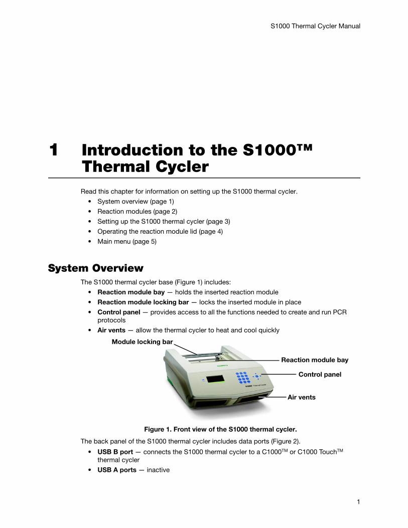
System OverviewThe S1000 thermal cycler base (Figure 1) includes:
• Reaction module bay — holds the inserted reaction module
• Reaction module locking bar — locks the inserted module in place
• Control panel — provides access to all the functions needed to create and run PCR protocols
• Air vents — allow the thermal cycler to heat and cool quickly
Figure 1. Front view of the S1000 thermal cycler.
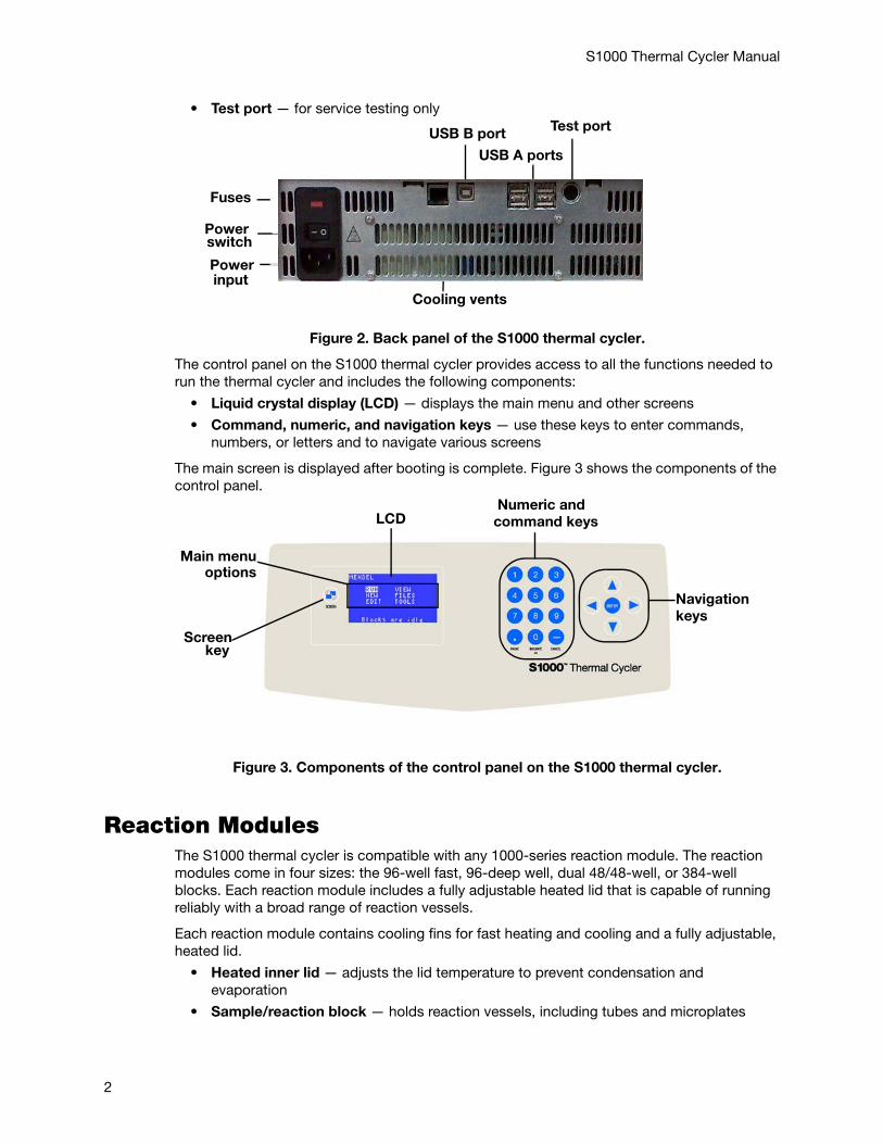
The back panel of the S1000 thermal cycler includes data ports (Figure 2).
• USB B port — connects the S1000 thermal cycler to a C1000TM or C1000 TouchTM thermal cycler
• USB A ports — inactive
Module locking bar
Control panel
Air vents
Reaction module bay
1
S1000 Thermal Cycler Manual
• Test port — for service testing only
Figure 2. Back panel of the S1000 thermal cycler.
The control panel on the S1000 thermal cycler provides access to all the functions needed to run the thermal cycler and includes the following components:
• Liquid crystal display (LCD) — displays the main menu and other screens
• Command, numeric, and navigation keys — use these keys to enter commands, numbers, or letters and to navigate various screens
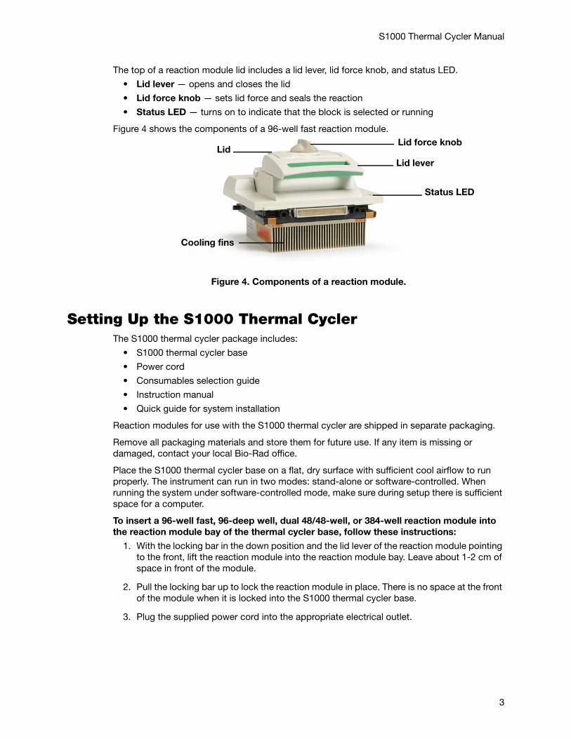
The main screen is displayed after booting is complete. Figure 3 shows the components of the control panel.
Figure 3. Components of the control panel on the S1000 thermal cycler.
Reaction ModulesThe S1000 thermal cycler is compatible with any 1000-series reaction module. The reaction modules come in four sizes: the 96-well fast, 96-deep well, dual 48/48-well, or 384-well blocks. Each reaction module includes a fully adjustable heated lid that is capable of running reliably with a broad range of reaction vessels.
Each reaction module contains cooling fins for fast heating and cooling and a fully adjustable, heated lid.
• Heated inner lid — adjusts the lid temperature to prevent condensation and evaporation
• Sample/reaction block — holds reaction vessels, including tubes and microplates
Cooling vents
Power
Power
USB B port
USB A ports
Test port
input
Fuses
switch
Main menu
Screen
options
Numeric and command keysLCD
key
Navigationkeys
2
S1000 Thermal Cycler Manual
The top of a reaction module lid includes a lid lever, lid force knob, and status LED.
• Lid lever — opens and closes the lid
• Lid force knob — sets lid force and seals the reaction
• Status LED — turns on to indicate that the block is selected or running
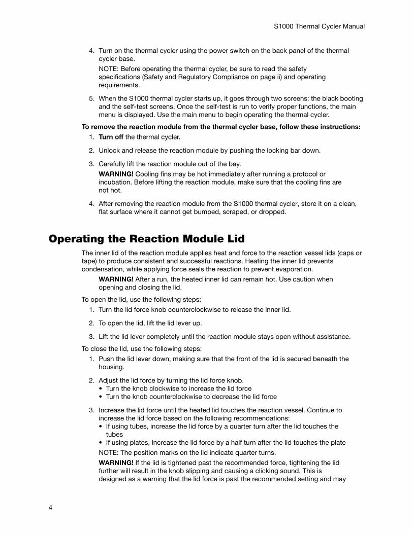
Figure 4 shows the components of a 96-well fast reaction module.
Figure 4. Components of a reaction module.
Setting Up the S1000 Thermal CyclerThe S1000 thermal cycler package includes:
• S1000 thermal cycler base
• Power cord
• Consumables selection guide
• Instruction manual
• Quick guide for system installation
Reaction modules for use with the S1000 thermal cycler are shipped in separate packaging.
Remove all packaging materials and store them for future use. If any item is missing or damaged, contact your local Bio-Rad office.
Place the S1000 thermal cycler base on a flat, dry surface with sufficient cool airflow to run properly. The instrument can run in two modes: stand-alone or software-controlled. When running the system under software-controlled mode, make sure during setup there is sufficient space for a computer.
To insert a 96-well fast, 96-deep well, dual 48/48-well, or 384-well reaction module into the reaction module bay of the thermal cycler base, follow these instructions:
1. With the locking bar in the down position and the lid lever of the reaction module pointing to the front, lift the reaction module into the reaction module bay. Leave about 1-2 cm of space in front of the module.
2. Pull the locking bar up to lock the reaction module in place. There is no space at the front of the module when it is locked into the S1000 thermal cycler base.
3. Plug the supplied power cord into the appropriate electrical outlet.
Lid force knob
Lid lever
Status LED
Lid
Cooling fins
3
S1000 Thermal Cycler Manual
4. Turn on the thermal cycler using the power switch on the back panel of the thermal cycler base.
NOTE: Before operating the thermal cycler, be sure to read the safety specifications (Safety and Regulatory Compliance on page ii) and operating requirements.
5. When the S1000 thermal cycler starts up, it goes through two screens: the black booting and the self-test screens. Once the self-test is run to verify proper functions, the main menu is displayed. Use the main menu to begin operating the thermal cycler.
To remove the reaction module from the thermal cycler base, follow these instructions:
1. Turn off the thermal cycler.
2. Unlock and release the reaction module by pushing the locking bar down.
3. Carefully lift the reaction module out of the bay.
WARNING! Cooling fins may be hot immediately after running a protocol or incubation. Before lifting the reaction module, make sure that the cooling fins are not hot.
4. After removing the reaction module from the S1000 thermal cycler, store it on a clean, flat surface where it cannot get bumped, scraped, or dropped.
Operating the Reaction Module LidThe inner lid of the reaction module applies heat and force to the reaction vessel lids (caps or tape) to produce consistent and successful reactions. Heating the inner lid prevents condensation, while applying force seals the reaction to prevent evaporation.
WARNING! After a run, the heated inner lid can remain hot. Use caution when opening and closing the lid.
To open the lid, use the following steps:
1. Turn the lid force knob counterclockwise to release the inner lid.
2. To open the lid, lift the lid lever up.
3. Lift the lid lever completely until the reaction module stays open without assistance.
To close the lid, use the following steps:
1. Push the lid lever down, making sure that the front of the lid is secured beneath the housing.
2. Adjust the lid force by turning the lid force knob.• Turn the knob clockwise to increase the lid force• Turn the knob counterclockwise to decrease the lid force
3. Increase the lid force until the heated lid touches the reaction vessel. Continue to increase the lid force based on the following recommendations:• If using tubes, increase the lid force by a quarter turn after the lid touches the
tubes• If using plates, increase the lid force by a half turn after the lid touches the plate
NOTE: The position marks on the lid indicate quarter turns.
WARNING! If the lid is tightened past the recommended force, tightening the lid further will result in the knob slipping and causing a clicking sound. This is designed as a warning that the lid force is past the recommended setting and may
4
S1000 Thermal Cycler Manual
result in damage to the reaction vessels. If this happens, decrease the lid force by turning the lid force knob counterclockwise 1 full turn. Re-apply the correct lid force by following the instructions above.
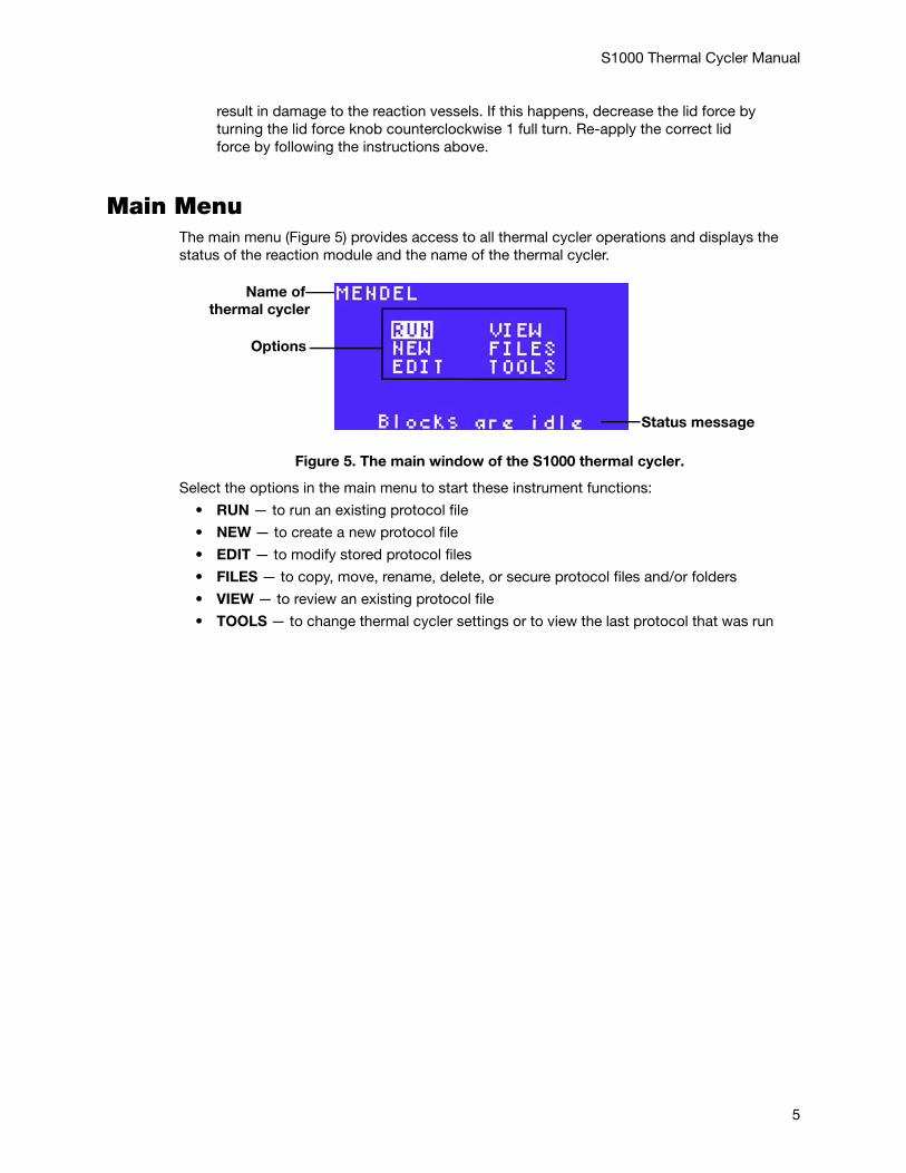
Main Menu The main menu (Figure 5) provides access to all thermal cycler operations and displays the status of the reaction module and the name of the thermal cycler.
Figure 5. The main window of the S1000 thermal cycler.
Select the options in the main menu to start these instrument functions:
• RUN — to run an existing protocol file
• NEW — to create a new protocol file
• EDIT — to modify stored protocol files
• FILES — to copy, move, rename, delete, or secure protocol files and/or folders
• VIEW — to review an existing protocol file
• TOOLS — to change thermal cycler settings or to view the last protocol that was run
Name of
Status message
thermal cycler
Options
5

S1000 Thermal Cycler Manual
6
S1000 Thermal Cycler Manual
2 Creating and Editing ProtocolsRead this chapter for information on creating and editing protocols.
• Creating a new protocol (page 7)
• Editing an existing protocol (page 10)
• Sample volume and lid temperature (page 12)
Creating a New Protocol NOTE: The internal memory of the S1000™ thermal cycler can hold up to 400 two-step protocols.
To create a protocol:
1. Select NEW from the main menu. Press ENTER to confirm the selection.
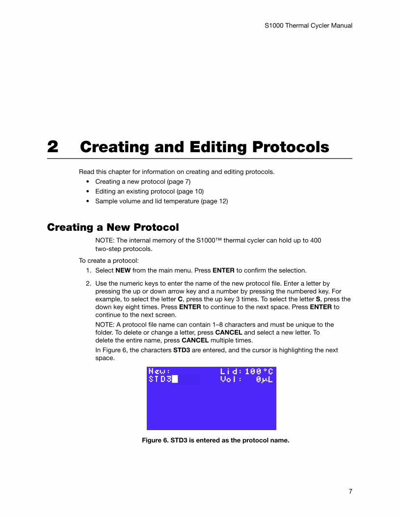
2. Use the numeric keys to enter the name of the new protocol file. Enter a letter by pressing the up or down arrow key and a number by pressing the numbered key. For example, to select the letter C, press the up key 3 times. To select the letter S, press the down key eight times. Press ENTER to continue to the next space. Press ENTER to continue to the next screen.
NOTE: A protocol file name can contain 1–8 characters and must be unique to the folder. To delete or change a letter, press CANCEL and select a new letter. To delete the entire name, press CANCEL multiple times.
In Figure 6, the characters STD3 are entered, and the cursor is highlighting the next space.
Figure 6. STD3 is entered as the protocol name.
7
S1000 Thermal Cycler Manual
3. Using the arrow keys, select TEMP to enter a temperature step or GRAD to enter a gradient temperature step in the protocol file. Press ENTER to continue to the next screen.
NOTE: The first step in a protocol must be either a TEMP or GRAD step.
4. Enter the target temperature between 0 (zero) and 100.0°C for the temperature step. Press ENTER to continue to the next screen.
5. Enter the hold time (TIME) in minutes and seconds using the numeric keys. The hold time (TIME) ranges between 0:01 (one second) and 18:00:00 (18 hours). Entering 0 (zero) adds an infinite hold and holds this step forever. Press ENTER to continue to the next screen.
6. Select YES, NO, or OPTION by pressing the right and left arrow keys.• YES — to confirm the current parameters for this protocol step• NO — to change a parameter in this protocol step • OPTION — to add more parameters to this protocol step. For more information
about entering options, see Adding an Option to a Temperature Step (page 10)Press ENTER to continue to the next screen.
7. Enter the lower temperature in the gradient. The lower temperature is at the front (row H) of the block.
8. Enter the upper temperature in the gradient. The upper temperature is at the back (row A) of the block.
NOTE: The range of temperatures is limited by the widest available range for gradient, which is 24°C. The highest value that can be entered for the upper temperature is 100°C.
9. Enter a hold time between 0:01 (one second) and 18:00:00 (18 hours).
10.Select YES, NO, or OPTION by pressing the right and left arrow keys.• YES — to confirm the current parameters for this protocol step• NO — to change a parameter in this protocol step • OPTION — to preview the temperature gradient. If Option is selected, select
VIEW on the next screen to view the gradient or EXT to add a hold time extension.Press ENTER to continue to the next screen.
11.Repeat the instructions in steps 5–8 to continue entering additional temperature steps.
NOTE: A protocol can contain up to 99 protocol steps. The first step must be a temperature (TEMP) step, while the last step must be an END step.
12.(Optional) To enter a GOTO step immediately after the set of steps to be repeated in a cycle, use the arrow keys and select GOTO. Press ENTER to continue to the next screen.
8
S1000 Thermal Cycler Manual
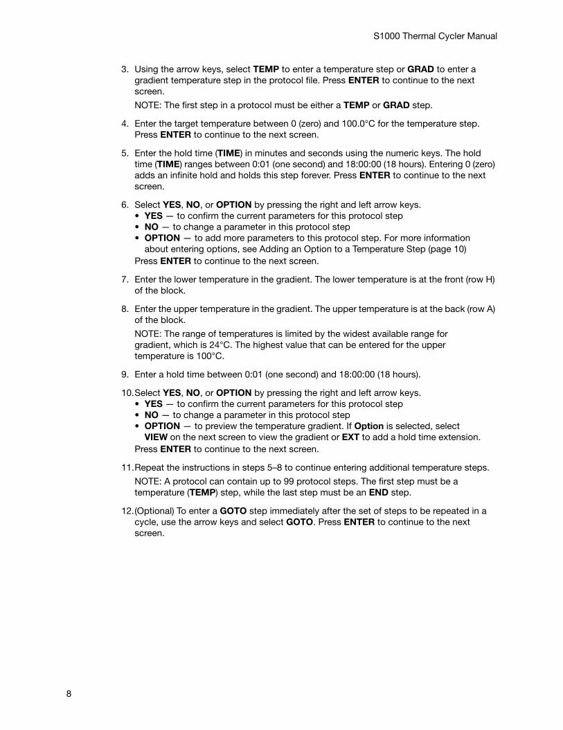
In Figure 7, step 5 is a GOTO step.
Figure 7. A GOTO step is selected.
NOTE: The GOTO step cannot be the first or the last step in the protocol.
13.Enter the step number for the first step in the GOTO repeats using the numeric keys. Press ENTER to continue to the next screen.
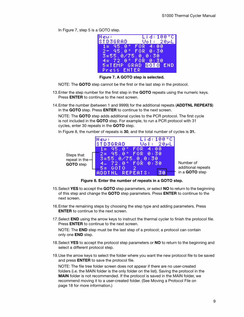
14.Enter the number (between 1 and 9999) for the additional repeats (ADDTNL REPEATS) in the GOTO step. Press ENTER to continue to the next screen.
NOTE: The GOTO step adds additional cycles to the PCR protocol. The first cycle is not included in the GOTO step. For example, to run a PCR protocol with 31 cycles, enter 30 repeats in the GOTO step.
In Figure 8, the number of repeats is 30, and the total number of cycles is 31.
Figure 8. Enter the number of repeats in a GOTO step.
15.Select YES to accept the GOTO step parameters, or select NO to return to the beginning of this step and change the GOTO step parameters. Press ENTER to continue to the next screen.
16.Enter the remaining steps by choosing the step type and adding parameters. Press ENTER to continue to the next screen.
17.Select END using the arrow keys to instruct the thermal cycler to finish the protocol file. Press ENTER to continue to the next screen.
NOTE: The END step must be the last step of a protocol; a protocol can contain only one END step.
18.Select YES to accept the protocol step parameters or NO to return to the beginning and select a different protocol step.
19.Use the arrow keys to select the folder where you want the new protocol file to be saved and press ENTER to save the protocol file.
NOTE: The file tree folder screen does not appear if there are no user-created folders (i.e. the MAIN folder is the only folder on the list). Saving the protocol in the MAIN folder is not recommended. If the protocol is saved in the MAIN folder, we recommend moving it to a user-created folder. (See Moving a Protocol File on page 18 for more information.)
Number ofadditional repeatsin a GOTO step
Steps that repeat in theGOTO step
9
S1000 Thermal Cycler Manual
Adding an Option to a Temperature StepTo add an option:
1. Select OPTION using the arrow keys. Press ENTER to continue to the next screen.
2. Select the option you want to add to the protocol step using the arrow keys. Press ENTER to continue to the next screen.
3. Enter the option value using the numeric keys.
4. To confirm the parameters of the protocol step, select YES and then press ENTER. To change the parameters, select NO and then press ENTER.
Editing an Existing Protocol NOTE: A protocol that is already running cannot be edited. Changes made in a protocol that is running apply to the next time the protocol runs. To stop editing a protocol, press CANCEL several times.
Editing the Lid Temperature and Sample VolumeTo edit an existing protocol:
1. Select EDIT from the main menu. Press ENTER to confirm the selection.
2. Using the arrow keys, select the folder that contains the protocol file to be edited. Press ENTER to continue to the next screen.
3. Enter the new lid temperature (optional) or use the default lid temperature. Press ENTER to accept the lid temperature and continue to the next screen.
NOTE: The lid temperature can range from 0 to 110°C. When the block is running an infinite hold at a temperature below the Turn off below parameter, the lid heater maintains 31.0°C. To change the default Turn off below parameter, select TOOLS > DEFAULTS.
4. Enter a new sample volume (optional) or use the default volume. Press ENTER to continue to the next screen.
Inserting a Protocol Step1. Select EDIT from the main menu. Press ENTER to confirm the selection.
2. Using the arrow keys, select the folder that contains the protocol file to be edited. Press ENTER to continue to the next screen.
3. Select a protocol step to edit using the arrow keys. Press ENTER to continue editing the step.
4. Select INS to insert a step above the selected protocol step.
5. Select TEMP, GRAD, or GOTO as the type of protocol step to be inserted. Press ENTER to continue to the next screen.
6. Enter the step parameters. Press ENTER to confirm each parameter.
7. Enter the parameters of the new step. Press ENTER to confirm each parameter.
10
S1000 Thermal Cycler Manual
Deleting a Protocol Step 1. Select EDIT from the main menu. Press ENTER to confirm the selection.
2. Using the arrow keys, select the folder that contains the protocol file to be edited. Press ENTER to continue to the next screen.
3. Select a protocol step to delete using the arrow keys. Press ENTER to continue editing the step.
4. Select DEL to delete the selected protocol step. Press ENTER to continue to the next screen. Notice that the deleted step parameters are replaced with the parameters of the next step.
5. Confirm the deletion. When prompted with Save changes?, select YES and press ENTER to delete the step. Alternatively, select NO and press ENTER to return to the beginning of this step.
Editing a Protocol StepTo change the parameters in existing protocol steps, use the following instructions:
1. Select EDIT from the main menu. Press ENTER to confirm the selection.
2. Using the arrow keys, select the folder that contains the protocol file to be edited. Press ENTER to continue to the next screen.
3. Select a protocol step to delete using the arrow keys. Press ENTER to continue editing the step.
4. Select EDIT to delete the selected protocol step. Press ENTER to continue to the next screen.
TIP: When you first select EDIT, you can edit the parameters in the selected protocol step. To edit the parameters in a different protocol step, press the arrow keys to go to that step.
5. Change the first parameter in the step by pressing the keys on the control panel to enter the temperature. Press ENTER to continue to the next parameter.
6. Change the second parameter in the step by pressing the numeric keys to type a new parameter. Press ENTER to continue to continue to the next step.
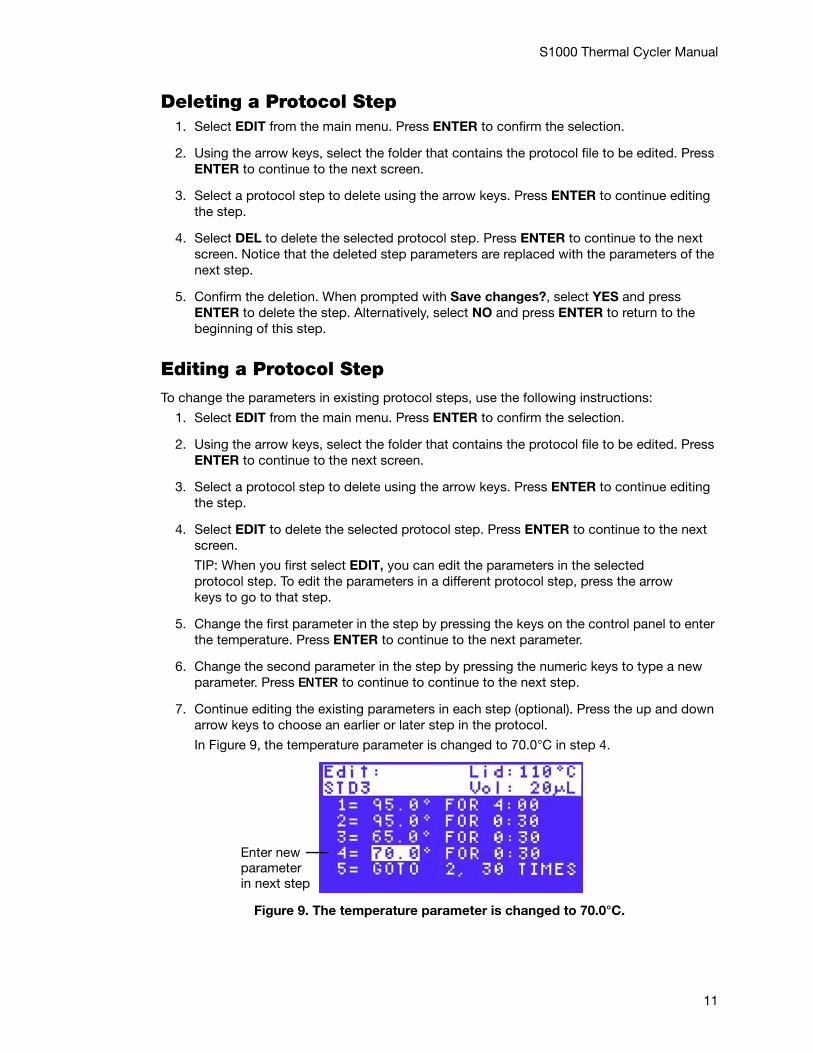
7. Continue editing the existing parameters in each step (optional). Press the up and down arrow keys to choose an earlier or later step in the protocol.
In Figure 9, the temperature parameter is changed to 70.0°C in step 4.
Figure 9. The temperature parameter is changed to 70.0°C.
Enter newparameterin next step
11
S1000 Thermal Cycler Manual
8. Press ENTER to finish changing parameters in the step and to continue editing the protocol.
Sample Volume and Lid TemperatureThe sample volume and lid temperature influence the outcome of a PCR protocol.
• Sample volume — determines the temperature control mode, which influences the amount of time the samples are held at the target temperature
• Lid temperature settings — determine the temperature of the heated lid and when it cuts off. If the temperature is too high, the sample temperature might rise above the target temperature
Temperature Control ModesThe S1000 thermal cycler uses one of two temperature control modes to determine when the sample reaches the target temperature:
• Calculated mode — The thermal cycler calculates the sample temperature based on the sample volume when a sample volume between 1 and 50 μl is entered for 96-well or dual 48/48-well reaction modules, a volume between 1 and 30 μl is entered for the 384-well reaction module, or a volume between 1 and 125 μl is entered for the 96-deep well reaction module. The calculated mode is recommended, because it most accurately represents the actual sample temperature
• Block mode — When a sample volume of zero (0) μl is entered, the thermal cycler assumes that the sample temperature is the same as the measured block temperature
12
S1000 Thermal Cycler Manual
3 Running ProtocolsRead this chapter for information on setting up the S1000™ thermal cycler.
• Preparing to run a protocol (page 13)
• Monitoring the protocol run (page 14)
• Canceling a run (page 15)
• Incubating samples (page 15)
Preparing to Run a ProtocolNOTE: You can run a protocol in a secure folder without entering the password first. See Securing Files in a Folder on page 19 for more information about files in secure folders.
To run a protocol:
1. Load the samples in the block. Close the lid and set the lid force using instructions on page 4.
2. Select RUN from the main menu. Press ENTER to confirm the selection and continue to the next screen.
NOTE: The main menu status should show Block is idle. With a dual 48/48-well reaction module, the status message is Blocks are idle when both blocks are available to run a protocol.
3. Select a folder that contains the protocol file of interest, then press the right arrow key to select the file. Press ENTER to confirm the selection and continue to the next screen.
NOTE: Select a protocol from the preinstalled protocols from the MAIN folder or any user folder in the file tree.
13
S1000 Thermal Cycler Manual
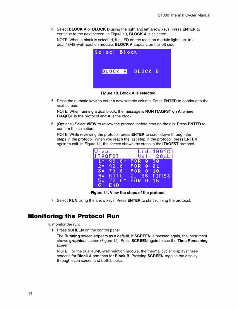
4. Select BLOCK A or BLOCK B using the right and left arrow keys. Press ENTER to continue to the next screen. In Figure 10, BLOCK A is selected.
NOTE: When a block is selected, the LED on the reaction module lights up. In a dual 48/48-well reaction module, BLOCK A appears on the left side.
Figure 10. Block A is selected.
5. Press the numeric keys to enter a new sample volume. Press ENTER to continue to the next screen.
NOTE: When running a dual block, the message is RUN ITAQFST on A, where ITAQFST is the protocol and A is the block.
6. (Optional) Select VIEW to review the protocol before starting the run. Press ENTER to confirm the selection.
NOTE: While reviewing the protocol, press ENTER to scroll down through the steps in the protocol. When you reach the last step in the protocol, press ENTER again to exit. In Figure 11, the screen shows the steps in the ITAQFST protocol.
Figure 11. View the steps of the protocol.
7. Select RUN using the arrow keys. Press ENTER to start running the protocol.
Monitoring the Protocol Run To monitor the run:
1. Press SCREEN on the control panel.
The Running screen appears as a default. If SCREEN is pressed again, the instrument shows graphical screen (Figure 12). Press SCREEN again to see the Time Remaining screen.
NOTE: For the dual 48/48-well reaction module, the thermal cycler displays these screens for Block A and then for Block B. Pressing SCREEN toggles the display through each screen and both blocks.
14
S1000 Thermal Cycler Manual
.
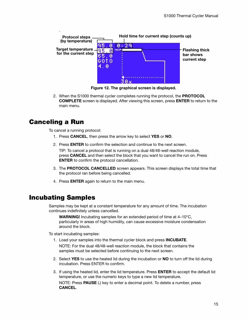
Figure 12. The graphical screen is displayed.
2. When the S1000 thermal cycler completes running the protocol, the PROTOCOL COMPLETE screen is displayed. After viewing this screen, press ENTER to return to the main menu.
Canceling a RunTo cancel a running protocol:
1. Press CANCEL, then press the arrow key to select YES or NO.
2. Press ENTER to confirm the selection and continue to the next screen.
TIP: To cancel a protocol that is running on a dual 48/48-well reaction module, press CANCEL and then select the block that you want to cancel the run on. Press ENTER to confirm the protocol cancellation.
3. The PROTOCOL CANCELLED screen appears. This screen displays the total time that the protocol ran before being cancelled.
4. Press ENTER again to return to the main menu.
Incubating SamplesSamples may be kept at a constant temperature for any amount of time. The incubation continues indefinitely unless cancelled.
WARNING! Incubating samples for an extended period of time at 4–10°C, particularly in areas of high humidity, can cause excessive moisture condensation around the block.
To start incubating samples:
1. Load your samples into the thermal cycler block and press INCUBATE.
NOTE: For the dual 48/48-well reaction module, the block that contains the samples must be selected before continuing to the next screen.
2. Select YES to use the heated lid during the incubation or NO to turn off the lid during incubation. Press ENTER to confirm.
3. If using the heated lid, enter the lid temperature. Press ENTER to accept the default lid temperature, or use the numeric keys to type a new lid temperature.
NOTE: Press PAUSE (.) key to enter a decimal point. To delete a number, press CANCEL.
Flashing thickbar shows current step
Hold time for current step (counts up)Protocol steps(by temperature)
Target temperaturefor the current step
15
S1000 Thermal Cycler Manual
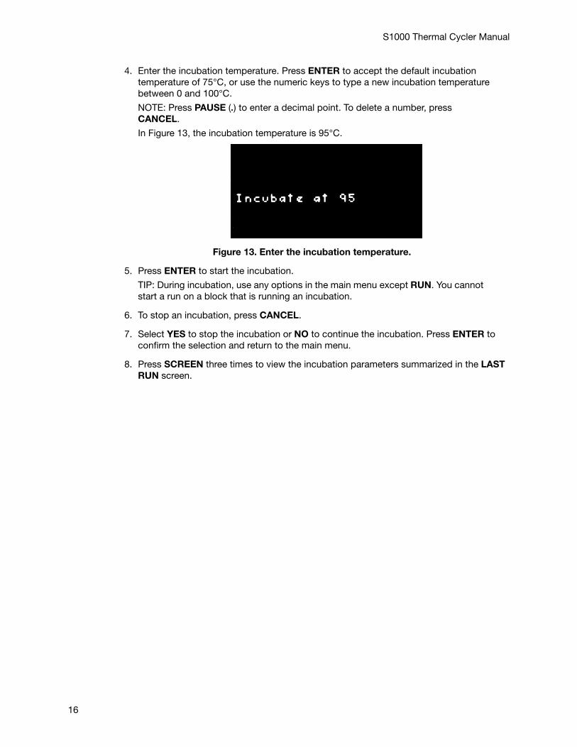
4. Enter the incubation temperature. Press ENTER to accept the default incubation temperature of 75°C, or use the numeric keys to type a new incubation temperature between 0 and 100°C.
NOTE: Press PAUSE (.) to enter a decimal point. To delete a number, press CANCEL.
In Figure 13, the incubation temperature is 95°C.
Figure 13. Enter the incubation temperature.
5. Press ENTER to start the incubation.
TIP: During incubation, use any options in the main menu except RUN. You cannot start a run on a block that is running an incubation.
6. To stop an incubation, press CANCEL.
7. Select YES to stop the incubation or NO to continue the incubation. Press ENTER to confirm the selection and return to the main menu.
8. Press SCREEN three times to view the incubation parameters summarized in the LAST RUN screen.
16
S1000 Thermal Cycler Manual
4 Managing Protocol Files and FoldersRead this chapter for information on managing protocol files and folders.
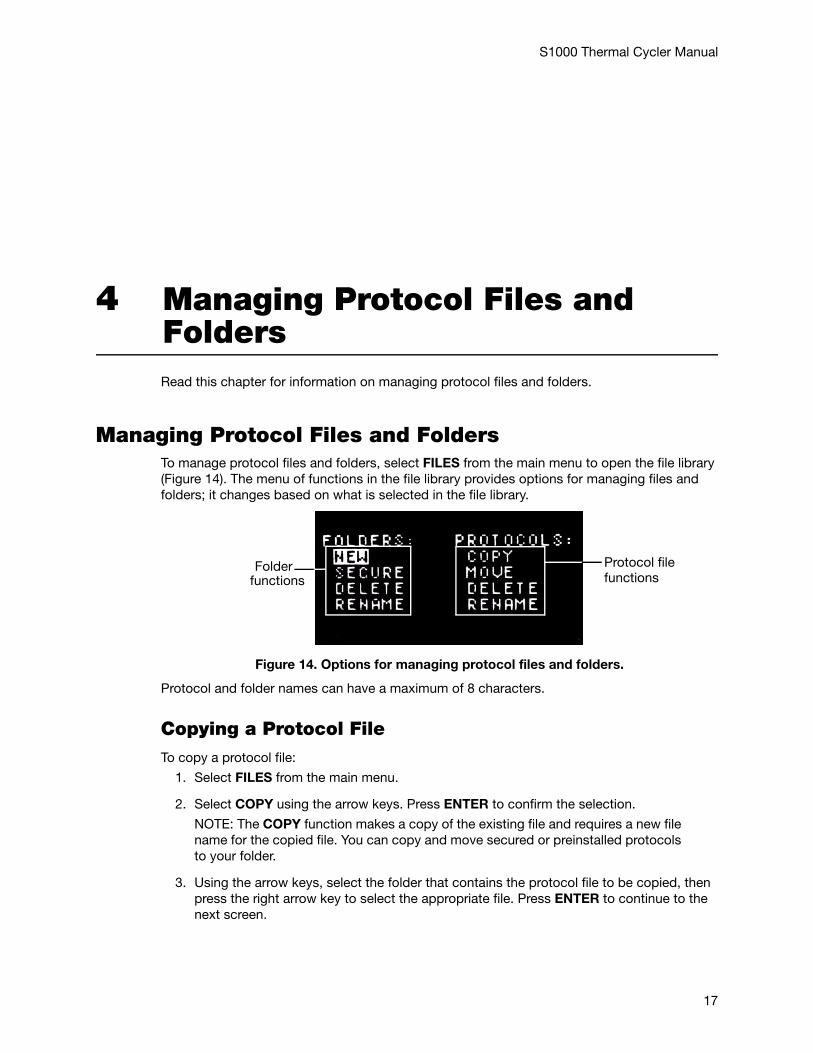
Managing Protocol Files and Folders To manage protocol files and folders, select FILES from the main menu to open the file library (Figure 14). The menu of functions in the file library provides options for managing files and folders; it changes based on what is selected in the file library.
Figure 14. Options for managing protocol files and folders.
Protocol and folder names can have a maximum of 8 characters.
Copying a Protocol File To copy a protocol file:
1. Select FILES from the main menu.
2. Select COPY using the arrow keys. Press ENTER to confirm the selection.
NOTE: The COPY function makes a copy of the existing file and requires a new file name for the copied file. You can copy and move secured or preinstalled protocols to your folder.
3. Using the arrow keys, select the folder that contains the protocol file to be copied, then press the right arrow key to select the appropriate file. Press ENTER to continue to the next screen.
functionsProtocol filefunctions
Folder
17
S1000 Thermal Cycler Manual
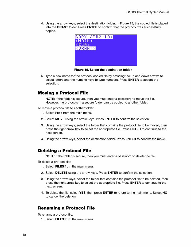
4. Using the arrow keys, select the destination folder. In Figure 15, the copied file is placed into the GRANT folder. Press ENTER to confirm that the protocol was successfully copied.
Figure 15. Select the destination folder.
5. Type a new name for the protocol copied file by pressing the up and down arrows to select letters and the numeric keys to type numbers. Press ENTER to accept the selection.
Moving a Protocol FileNOTE: If the folder is secure, then you must enter a password to move the file. However, the protocols in a secure folder can be copied to another folder.
To move a protocol file to another folder:
1. Select Files from the main menu.
2. Select MOVE using the arrow keys. Press ENTER to confirm the selection.
3. Using the arrow keys, select the folder that contains the protocol file to be moved, then press the right arrow key to select the appropriate file. Press ENTER to continue to the next screen.
4. Using the arrow keys, select the destination folder. Press ENTER to confirm the move.
Deleting a Protocol File NOTE: If the folder is secure, then you must enter a password to delete the file.
To delete a protocol file:
1. Select FILES from the main menu.
2. Select DELETE using the arrow keys. Press ENTER to confirm the selection.
3. Using the arrow keys, select the folder that contains the protocol file to be deleted, then press the right arrow key to select the appropriate file. Press ENTER to continue to the next screen.
4. To delete the file, select YES, then press ENTER to return to the main menu. Select NO to cancel the deletion.
Renaming a Protocol File To rename a protocol file:
1. Select FILES from the main menu.
18
S1000 Thermal Cycler Manual
2. Select RENAME using the arrow keys. Press ENTER to confirm the selection.
3. Using the arrow keys, select the folder that contains the protocol file to be renamed, then press the right arrow key to select the appropriate file. Press ENTER to continue to the next screen.
4. Enter a new protocol file name using the up and down arrows to select letters and the numeric keys to type numbers. Press ENTER to accept the new name and return to the main menu.
Creating a New Folder The S1000™ thermal cycler can contain 11 folders in addition to the MAIN folder. Protocol files are stored in the MAIN folder by default; however, it is highly recommended that files be stored in user-created folders for easy access and ability to password-protect the files.
To create a new folder:
1. Select FILES from the main menu.
2. Select NEW from the menu using the arrow keys. Press ENTER to confirm the selection.
3. Enter the folder name using the up and down arrows to select letters and the numeric keys to type numbers. Press ENTER to accept the new name and return to the main menu.
Securing Files in a Folder Securing folders with a password prevents other users from editing, deleting, or moving your files from the S1000 thermal cycler.
NOTE: To edit, move, or delete files stored in a secure folder, a password must be entered. However, a password is not required for viewing, copying, or running protocol files that are located in a secure folder.
To secure a folder with a password or to change an existing password:
1. Select FILES from the main menu.
2. Select SECURE using the arrow keys. Press ENTER to confirm the selection and continue to the next screen.
3. Select the folder to be secured using the up and down arrows.
NOTE: To change a password, you need to enter the original password first. If the password is lost, protocols in the secured folder cannot be deleted, moved, or edited. Furthermore, the folder cannot be deleted.
4. Enter a new password using the numeric keys to type numbers. Press ENTER to confirm the password and return to the main menu.
NOTE: A password can contain one to four numbers and cannot contain letters.
TIP: To disable security for a folder, repeat steps 1–4, and specify a blank, new password.
Deleting a Folder NOTE: A folder that contains protocol files cannot be deleted. Select VIEW in the main menu to view the contents of the folder before deleting the folder. Delete or
19
S1000 Thermal Cycler Manual
move all protocol files before deleting the folder. Once a folder is deleted, it is permanently removed.
To delete a folder:
1. Select FILES from the main menu.
2. Select DELETE using the arrow keys. Press ENTER to confirm the selection.
3. Using the arrow keys, select the folder to be deleted. Press ENTER to continue to the next screen.
4. To delete the folder, select YES, then press ENTER to return to the main menu. Select NO to cancel the deletion.
Renaming a FolderNOTE: Renaming a folder does not change the protocol files stored in the folder. To rename a folder that is secure, enter the password before typing the name.
To rename a folder:
1. Select FILES from the main menu.
2. Select RENAME using the arrow keys. Press ENTER to confirm the selection.
3. Using the arrow keys, select the folder to be renamed. Press ENTER to continue to the next screen.
4. Enter the new folder name using the up and down arrows to select letters and the numeric keys to type numbers. Press ENTER to accept the new name and return to the main menu.
20
S1000 Thermal Cycler Manual
5 Advanced Tools and FunctionsRead this chapter for information on advanced tools and functions on the S1000™ thermal cycler.
• TOOLS options (page 21)
• Controlling S1000 thermal cyclers with a C1000™ or C1000 TouchTM thermal cycler (page 21)
TOOLS OptionsTo see the list of instrument settings and tools:
1. Select TOOLS from the main menu. The following functions are available in the TOOLS option:• LAST RUN — to view the last protocol that was run • SELF TEST — to run a self test on the thermal cycler • VERSION — to view the current instrument firmware version • NAME — to enter a name for the thermal cycler • DEFAULTS — to change default lid temperature, “turn off below” feature, and
sample volume • GRADCALC — to view a temperature gradient based on user-defined parameters • CONTRAST — to change the instrument’s LCD contrast• PORT — to change the port used to control the S1000 thermal cycler remotely
2. To return to the main menu, press ENTER.
Controlling S1000 Thermal Cyclers with a C1000™ or C1000 TouchTM
The S1000 thermal cycler can be run in stand-alone single instrument, stand-alone multi-instrument, or software-controlled multi-instrument configuration. In stand-alone multi-instrument configuration, up to three S1000 thermal cyclers can be run under the control of a C1000 or C1000 Touch thermal cycler. Each S1000 thermal cycler can be connected to the USB A port of the C1000 or C1000 Touch thermal cycler.
When connected to a C1000 thermal cycler, the S1000 thermal cyclers can be controlled by either the C1000 thermal cycler or C1000 Manager™ software.
21
S1000 Thermal Cycler Manual
When connected to a C1000 Touch thermal cycler, the S1000 thermal cyclers can be controlled by either the C1000 Touch thermal cycler or CFX Manager™ software, 2.0 or higher.
Connecting S1000 Cyclers Directly to a C1000 or C1000 Touch CyclerTo connect up to three S1000 thermal cyclers directly to a C1000 or C1000 Touch thermal cycler, follow these instructions:
1. Plug a high quality, shielded USB cable into the USB B port on the back of the S1000 thermal cycler.
2. Plug the other end of the USB cable into a USB A port on the back of the C1000 or C1000 Touch thermal cycler.
3. Repeat steps 1 and 2 to connect up to three S1000 cyclers directly to the same C1000 or C1000 Touch thermal cycler.
4. Open the MAIN screen or instrument tree on the C1000 thermal cycler, or in the C1000 Manager software if the C1000 thermal cycler is connected to a computer.
5. Open the Saved Files screen on the C1000 Touch thermal cycler, or the instrument tree in the CFX Manager software if the C1000 Touch is connected to a computer.
6. Select the S1000 thermal cycler by serial number or name.
NOTE: If the S1000 thermal cycler instrument has a name, then the name is displayed instead of the serial number.
Operating the S1000 Thermal Cycler While It’s Under the Control of the C1000 or C1000 Touch Cycler When the S1000 thermal cycler is under the control of a C1000 or C1000 Touch thermal cycler, it is in “semi-lock down mode.” In this mode, the S1000 thermal cycler does not respond when control panel keys are pressed. However, the following keys function on the control panel:
• SCREEN — to access the running, graphical, and time-remaining screens
• PAUSE — to temporarily stop a protocol that is currently running on the S1000 thermal cycler. This function is active when an individual protocol screen is being displayed
• CANCEL — to cancel a protocol that is currently running on the S1000 thermal cycler. This function is active when an individual protocol screen is being displayed
• ENTER — to begin a run that has been remotely sent from the C1000 Manager or CFX Manager software
• ENTER — to skip a step. This function is active when an individual protocol screen is being displayed
22
S1000 Thermal Cycler Manual
6 Maintenance and TroubleshootingRead this chapter for information on maintaining the S1000™ thermal cycler and troubleshooting problems on the thermal cycler.
• Cleaning and maintaining the S1000 thermal cycler (page 23)
• Maintaining sufficient airflow (page 25)
• Replacing fuses (page 26)
Cleaning and Maintaining the S1000 Thermal Cycler The S1000 thermal cycler requires little maintenance for proper operation and precise thermal control. However, with long and constant use, the thermal cycler requires some cleaning and other maintenance. Information on cleaning the thermal cycler base and reaction module is included in this chapter. In addition, instructions on replacing the fuses are provided.
Cleaning the S1000 Thermal Cycler
The S1000 thermal cycler should be cleaned on a regular schedule to remove any debris or dirt that might interfere with proper function. Clean the base to prevent damage to the air intake or reaction module bay.
NOTE: For instructions on handling and cleaning radioactive or biohazardous materials, consult the guidelines for radiation safety and biosafety provided by your institution. These guidelines include cleaning, monitoring, and disposal methods for hazardous materials.
To clean the thermal cycler base, follow the instructions below, paying careful attention to the warnings:
WARNING! To prevent electrical shock, always turn off and unplug the instrument before cleaning it.
• Clean the air vents. Remove dust with a soft brush, damp cloth, or vacuum cleaner. Remove any heavy dust that is deep in the vents with a vacuum cleaner. Cleaning the vents allows sufficient airflow for precise thermal control during a run
• Clean the control panel. Remove debris on the control panel with a soft cloth and mild soap solution. Cleaning the panel prevents debris that may obscure the display
23
S1000 Thermal Cycler Manual
WARNING! Do not use abrasive detergents or rough material since they scratch the control panel.
• Clean the reaction module bay. Clean with a damp soft cloth to remove debris and spilled liquids. Cleaning the bay allows precise heating and cooling of the reaction block
WARNING! Never use cleaning solutions that are corrosive to aluminium. Avoid scratching the surface of the bay, which interferes with precise thermal control.
WARNING! Never pour water or other solutions in the reaction module bay. Wet components can cause electrical shock when the thermal cycler is plugged in.
• Clean the outside case of the thermal cycler base. Use a damp cloth or tissue to clean spills off the outside case. If needed, use a mild soap solution and remove the residue completely. Cleaning the outside case prevents corrosion
Cleaning the Reaction ModulesClean the reaction modules of the S1000 thermal cycler on a regular schedule to prevent reagents from accumulating and interfering with the ability of the reaction block to change temperature quickly.
To clean the reaction module, follow these instructions, paying careful attention to the warnings:
WARNING! To prevent electrical shock, always remove the reaction module from the thermal cycler base before cleaning it.
• Clean the cooling fins. Remove dust from the cooling fins with a soft brush or damp cloth. Remove any heavy dust that is deep in the fins with a vacuum cleaner. Use water and a soft cloth to remove debris that is stuck to the fins. Avoid scratching the surface. Never use cleaning solutions that are corrosive to aluminum, such as bleach or abrasive cleansers. If needed, use a mild soap solution and rinse well to remove the residue completely. Cleaning the fins improves precise sample heating and cooling
• Clean the outside cover of the reaction block. Use a soft cloth and water to remove debris from the outer block
WARNING! Never clean the block with strong alkaline solutions (strong soap, ammonia, or high-concentration bleach). Never use corrosive or abrasive cleaning solutions. These cleaning agents can damage the block and prevent precise thermal control.
• Clean the block wells. Clean spills immediately to prevent them from drying inside wells. Use disposable plastic pipets with water (recommended), 95% ethanol, or a 1:100 dilution of bleach in water. Always rinse the wells with water several times to remove all traces of ethanol, bleach, or soap
WARNING! If left in the block wells, bleach, ethanol, or soap could corrode the block and/or destroy tubes and microplates during a run. Always rinse the block well after cleaning it with any solution other than water.
• If oil is used, the wells must be cleaned thoroughly and often. Use of oil in the wells is not recommended. Clean the oil when it is discolored or contains dirt. Use a solution of 95% ethanol to clean oil. Do not allow oil to build up in the block
WARNING! Never heat the block after adding a cleaning solution. Heating the block with cleaning solution damages the block, lid, and thermal cycler base.
• Clean the inner lid of the reaction module. Use a soft cloth and water to remove debris and solutions from the inner lid surface. Never use abrasive detergents or rough material that scratch the surface. Cleaning the inner lid improves precise sample heating and cooling
24
S1000 Thermal Cycler Manual
• Clean the outer lid surface of the reaction module. Use a damp cloth or tissue to clean spills off the outside case. If needed, use a mild soap solution and rinse the surface with a damp cloth. Cleaning the cover prevents corrosion
Maintaining Sufficient AirflowThe S1000 thermal cycler requires sufficient airflow to precisely heat and cool to the correct target temperature. If the flow of air is blocked, the thermal cycler cannot ramp to the correct temperature in the specified time. This section includes instructions for testing the airflow and provides suggestions for fixing low or warm airflow.
Testing for Sufficient AirflowThe airflow is sufficient when the thermal cycler heats and cools to the correct target temperatures promptly. When the S1000 thermal cycler is first set up in a new location, use the following steps to determine the presence of sufficient airflow:
1. Set up the instrument in the location where it is going to be used, then turn the power on.
2. Adjust the local environment for typical conditions.
Turn on any nearby equipment, such as fans. Open any window blinds to reproduce typical conditions during a run. If more than one thermal cycler is in the area, run a protocol on all the thermal cyclers at the same time.
3. Run a typical PCR protocol for 30 mins.
To run a protocol, samples are not required; however, an empty microplate or tubes should be included. The lid does not heat correctly if it touches the hot block of the reaction module.
4. Measure the air temperature at the air intake vents of all the thermal cyclers.
If the air intake temperature exceeds 31°C, see Fixing Insufficient Airflow to ensure sufficient airflow.
Fixing Insufficient AirflowIf the air temperature near the thermal cycler is above 31°C, make one or more of the following changes to increase the flow of cooler air around the thermal cycler:
• Adjust air conditioning to lower the ambient air temperature
• Move the thermal cycler to another location
• Provide more space around the S1000 thermal cycler and between adjacent instruments. Arrange instruments so that warm exhaust air from one instrument does not enter the air intake vents of another
• Shield the thermal cycler from heat sources, such as radiators, other heat-producing instruments, and bright sunlight
25
S1000 Thermal Cycler Manual
Replacing FusesFuses on the S1000 thermal cycler are designed to blow in case of severe power surges or other causes of an electrical short. This process protects both the user and the instrument from excessive electric charge. Fuses on the S1000 thermal cycler rarely need to be replaced. However, some institutions prefer to replace fuses on a regular basis to maintain uninterrupted operation.
If the thermal cycler does not turn on, first check that the power cord is plugged in to a functioning power source. Also, check that the power cord and power source are within the specifications for this instrument. To replace the power cord, contact Bio-Rad Technical Support.
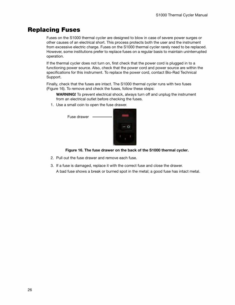
Finally, check that the fuses are intact. The S1000 thermal cycler runs with two fuses (Figure 16). To remove and check the fuses, follow these steps:
WARNING! To prevent electrical shock, always turn off and unplug the instrument from an electrical outlet before checking the fuses.
1. Use a small coin to open the fuse drawer.
Figure 16. The fuse drawer on the back of the S1000 thermal cycler.
2. Pull out the fuse drawer and remove each fuse.
3. If a fuse is damaged, replace it with the correct fuse and close the drawer.
A bad fuse shows a break or burned spot in the metal; a good fuse has intact metal.
Fuse drawer
26
S1000 Thermal Cycler Manual
Aair flow
cleaning air vents, 23increasing, 25maintaining, 25testing for, 25
air ventscleaning, 23
BBio-Rad Laboratories
contact information, iitechnical support, ii
CC1000 Manager software, 21, 22C1000 thermal cycler
connecting to S1000 cyclers, 22operating S1000 cyclers, 22warranty, ii
cancelling a run, 15cleaning the cycler, 23command keys, 2CONTRAST, 21control panel, 2
cleaning, 23liquid crystal display (LCD), 2on the C1000 thermal cycler, 21self-test screen, 4
controlling with a C1000 thermal cycler, 21, 22cooling fins, 2
cleaning, 24creating a new folder, 19creating a protocol, 7
Ddecimal point, 16DEFAULTS, 21deleting
folder, 19
Eediting a protocol
changing a protocol step, 11changing the lid temperature, 10
27
S1000 Thermal Cycler Manual
changing the sample volume, 10deleting a protocol step, 11inserting a protocol step, 10
Ffile tree, 9folder
creating new, 19deleting, 19password, 19renaming, 20
fusesreplacing, 26
GGOTO step
entering, 8GRADCALC, 21
Hhold time, 8
extending in a temperature step, 10
Iincubating samples, 15inserting reaction module, 3instrument tree, 22
LLAST RUN screen, 21LCD, 2LED, 3lid lever, 3lid temperature
role in PCR outcome, 12
Mmain menu
list of functions, 5options, 5
MAIN screen, 22
28
S1000 Thermal Cycler Manual
maintenancereaction modules, 24
managing protocol files, 17managing protocol folders, 17monitoring a run
PROTOCOL COMPLETE screen, 15Running screen, 14
NNAME, 21navigation keys, 2numeric keys, 2
Ppassword
changing, 19securing a folder, 19
plugging in thermal cycler, 3PORT, 21protocol
copying, 17deleting, 18managing files, 17managing folders, 17moving, 18renaming, 18
PROTOCOL COMPLETE screen, 15
Rreaction block
reaction vessels, 2reaction module bay
cleaning, 24reaction modules, 2
cleaning, 24closing the lid, 4cooling fins, 2installing, 3lid, 2lid force knob, 3lid lever, 3maintenance, 24opening the lid, 4operating lid, 4reaction block, 2recommended sample volumes, 2removing from cycler, 4
29
S1000 Thermal Cycler Manual
sample block, 2specifications, 2status LED, 3
recommended sample volumes, 2renaming
folder, 20protocol file, 18
repeatsadditional, 9
reviewing a protocol, 14running a protocol, 13
SS1000 thermal cycler
air flow, 25safety
compliance, ivwarning labels, iii
sample block, 2sample volume
role in PCR outcome, 12securing files, 19SELF TEST, 21self-test screen, 4service testing
test port, 2specifications
for safe use of instrument, ivregulatory compliance, iv
Ttechnical support
contact information, iitemperature control modes, 12
block mode, 12calculated mode, 12
temperature stepadding an increment, 10
test port, 2service testing, 2
TOOLS options, 21CONTRAST, 21DEFAULTS, 21GRADCALC, 21LAST RUN, 21NAME, 21PORT, 21SELF TEST, 21VERSION, 21
turning on thermal cycler, 4
30
S1000 Thermal Cycler Manual
Uunpacking thermal cycler, 3USB A ports, 1USB B port, 1, 22USB cable, 22
VVERSION, 21
Wwarning
labels on instrument, iiiwarranty, ii
31

12-1309 0912 Sig 121110010306 Rev E US/EG
Life ScienceGroup
Web site www.bio-rad.com USA 800 424 6723 Australia 61 2 9914 2800 Austria 01 877 89 01 Belgium 09 385 55 11 Brazil 55 31 3689 6600 Canada 905 364 3435 China 86 21 6169 8500 Czech Republic 420 241 430 532 Denmark 44 52 10 00 Finland 09 804 22 00 France 01 47 95 69 65 Germany 089 31 884 0 Greece 30 210 777 4396 Hong Kong 852 2789 3300 Hungary 36 1 459 6100 India 91 124 4029300 Israel 03 963 6050 Italy 39 02 216091 Japan 03 6361 7000 Korea 82 2 3473 4460 Malaysia 60 3 2117 5260 Mexico 52 555 488 7670 The Netherlands 0318 540666 New Zealand 64 9 415 2280 Norway 23 38 41 30 Poland 48 22 331 99 99 Portugal 351 21 472 7700 Russia 7 495 721 14 04 Singapore 65 6415 3170 South Africa 27 861 246 723 Spain 34 91 590 5200 Sweden 08 555 12700 Switzerland 061 717 95 55 Taiwan 886 2 2578 7189 Thailand 66 2 6518311 United Kingdom 020 8328 2000


