Instruction Sheet Rev. B No. 412767 ECO 12469 RADIO FREQUENCY SYSTEMS Radio Frequency Systems 200 Pondview Drive Meriden, CT 06450 Ph (203) 630-3311 Fax (203) 634-2272 www.rfsworld.com Radio Frequency Systems 200 Pondview Drive Meriden, CT 06450 Ph (203) 630-3311 Fax (203) 634-2272 www.rfsworld.com Install. Instr. for Microwave Parabolic Antennas ∅ 3.7 m (12 ft) It is important to mount the antenna exactly as described in these installation instructions. The installed antenna shall be inspected once per year by qualified personnel . RFS disclaims all responsibility for antenna malfunction due to improper or unsafe installation. These installation instructions have been written for qualified, skilled personnel. We reserve the right to alter details, especially with respect to technical improvement. Page 1 of 13 These Installation Instructions are valid for antennas in the following version: • reflector ∅ 3.7 m (12 ft) • waveguide feed single or dual polarized • pipe mount for installation on ∅115mm • antenna offset to the left or the right • safety collar for easy installation • 2 spindles for fine adjustment azimuth and elevation of ± 5 degrees • 1 sway bar • reflector (Standard) • reflector with shroud, shroud aperture covered by a radome (High-Performance)
Transcript
Instruction Sheet Rev. BNo. 412767
ECO 12469
RADIO FREQUENCY SYSTEMSRadio Frequency Systems200 Pondview DriveMeriden, CT 06450Ph (203) 630-3311Fax (203) 634-2272www.rfsworld.com
Radio Frequency Systems200 Pondview DriveMeriden, CT 06450Ph (203) 630-3311Fax (203) 634-2272www.rfsworld.com
Install. Instr. for Microwave Parabolic Antennas ∅ 3.7 m (12 ft)
It is important to mount the antenna exactly as described in these installation instructions.The installed antenna shall be inspected once per year by qualified personnel .RFS disclaims all responsibility for antenna malfunction due to improper or unsafe installation.These installation instructions have been written for qualified, skilled personnel.
We reserve the right to alter details, especially with respect to technical improvement. Page 1 of 13
These Installation Instructions are valid for antennas in the following version:
• reflector ∅ 3.7 m (12 ft)• waveguide feed single or dual polarized• pipe mount for installation on ∅115mm• antenna offset to the left or the right• safety collar for easy installation• 2 spindles for fine adjustment azimuth and elevation of ± 5 degrees• 1 sway bar• reflector (Standard)• reflector with shroud, shroud aperture covered by a radome (High-Performance)
rallen
RADIO FREQUENCY SYSTEMSRadio Frequency Systems200 Pondview DriveMeriden, CT 06450Ph (203) 630-3311Fax (203) 634-2272www.rfsworld.com
• Hoisting device for 8000 N
• Shackle • 2 ropes • Water balance and compass • Mallet • Wrenches for hexagon bolts: M5(8), M6(10), M10(17), M12(19), M14(21), M16(24), M20(30) (values in brackets = openings of spanners) • Torque wrench from 5 to 250 Nm • Nail set or punch for ∅ 6mm
Tools are not included with antenna :
1. Tools required for installation
2. Assembly of the mount
For easy operation of the bolted joints, « Anti Seize »Installation Paste should be applied to all threads of bolts and fine adjustment spindles except galv. hardware. See Page 12. After this, keep the lubricated threads free of dust and dirt! Fastener torque specification see table attached! See Page 13.
Page 2 of 13
2 screws M20x602 flat washers
2 spring lock washers 202 nuts M20
screw M20x50 flat washer spring lock washer 20 nut M20
Angle safety support
screw M20x60 flat washer spring lock washer 20 nut M20
screw M20x110 flat washer spring lock washer 20 nut M20
screw M20x50 flat washer spring lock washer 20 nut M20
AZIMUTH spindle M20x300 4 washers 21 4 nuts M20
3 U-bolts M12/60 6 washers 13 12 nuts M12
screw M20x60flat washer
spring lock washer 20nut M20
ELEVATIONPlate spindle M20x400
2 brass nuts M102 spherical washer C21
2 conical seats D232 washers 21 ∅ 60
2 screws M16x502 washers 17
2 spring lock washers 162 nuts M16
site-L
RADIO FREQUENCY SYSTEMSRadio Frequency Systems200 Pondview DriveMeriden, CT 06450Ph (203) 630-3311Fax (203) 634-2272www.rfsworld.com
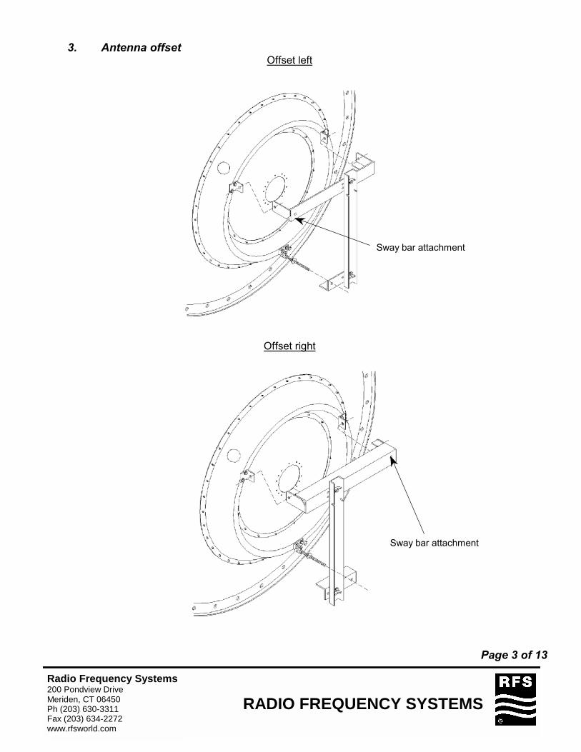
3. Antenna offset Offset left
Offset right
Sway bar attachment
Sway bar attachment
Page 3 of 13
RADIO FREQUENCY SYSTEMSRadio Frequency Systems200 Pondview DriveMeriden, CT 06450Ph (203) 630-3311Fax (203) 634-2272www.rfsworld.com
4. Sway bar positionning
2.1 Loose nut of mounting bracket. 2.2 Turn the mounting bracket in the right position. 2.3 Angle the sway bar. 2.4 After installation, tighten all nuts.
Important: Do not angle the sway bar more than 25 deg in any direction for tower installation !
max. +25 degrees
2.3
2.2
2.1 max. -25 degrees
Page 4 of 13
RADIO FREQUENCY SYSTEMSRadio Frequency Systems200 Pondview DriveMeriden, CT 06450Ph (203) 630-3311Fax (203) 634-2272www.rfsworld.com
5. Assembly of the shroud (only for High Performance Series)
6. Shroud Sections Attachement
• The rim of the reflector must be clean and dry • Stick on the RF gasket tape 360 deg in a way, that :
• all mounting holes are covered by the tape and • the wire mesh is directed to the center of reflector • position the shroud- clean and dry- onto the reflector.
Page 5 of 13
Complete reflector with mount
40 screws M6x3080 washers 6.4 ∅18mm*
40 sl nuts M6
Hoisting eye dismounted
∅ 6mm( punched after positioning of the shroud)
RF gasket tape, Self-adhesive
Wire mesh directed to center
of reflector
TOP
Edge protector
* For spots free of paint 90° a side TOP (left and right) add 2 serrated lock washers A6.4.
4 screws M6x25 4 sl nuts M6 8 washers 6.4 ∅18
Long shroud 11 screws M6x16 11 sl nuts M6 (short and middle section) 22 washers 6.4 ∅18 or 12 screws M6x16 12 sl nuts M6 (long section) 24 washers 6.4 ∅18 Short shroud 9* screws M6x16 9 nuts M6 (short section) 18 washers 6.4 ∅18 or 10 screws M6x16 10 sl nuts M6 (middle and long section) 20 washers 6.4 ∅18
RADIO FREQUENCY SYSTEMSRadio Frequency Systems200 Pondview DriveMeriden, CT 06450Ph (203) 630-3311Fax (203) 634-2272www.rfsworld.com
7. Feed installation
The feed is a precision component which should be handled with special care during installation. For instance, always carry the feed, supporting both ends. Any damage may degrade the antenna’s performance. Repair of feeds is not possible in the field.
7.1. Guy Wire Assemblies
• Insert the feed 3 guy wire assemblies into the mounting holes from the reflector rear, hang them into the feed guy ring. Please note: spring length + 2 washers = 30 mm
• Hang the guy wires into the rotatable guy ring • Fix the feed with the clamps brackets and screws M6, spring washers A6.4 • The length ‘’a’’ of all guy wires must be equal. The max. spring contraction during the
alignment is 5 mm.
Kevlar guy wire assembly rotatable feed guy ring
Page 6 of 13
RADIO FREQUENCY SYSTEMSRadio Frequency Systems200 Pondview DriveMeriden, CT 06450Ph (203) 630-3311Fax (203) 634-2272www.rfsworld.com
7.2. Single polarized antennas
Antenna TOP
Vertical Horizontal
7.3 Dual polarized antennas
Antenna TOP
clamp brackets with: screws M6 spring washers A6.4.
clamp brackets with : screws M6
spring washers A6.4.
Page 7 of 13
RADIO FREQUENCY SYSTEMSRadio Frequency Systems200 Pondview DriveMeriden, CT 06450Ph (203) 630-3311Fax (203) 634-2272www.rfsworld.com
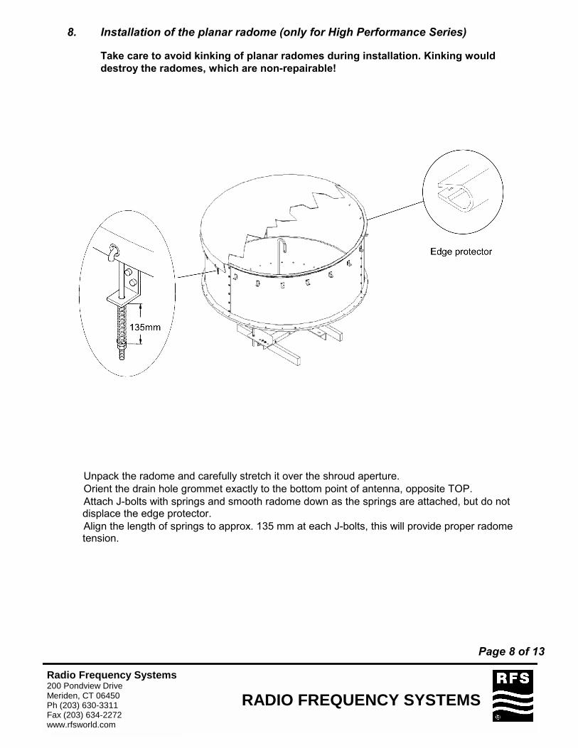
8. Installation of the planar radome (only for High Performance Series)
Take care to avoid kinking of planar radomes during installation. Kinking would destroy the radomes, which are non-repairable!
• Unpack the radome and carefully stretch it over the shroud aperture. • Orient the drain hole grommet exactly to the bottom point of antenna, opposite TOP. • Attach J-bolts with springs and smooth radome down as the springs are attached, but do not
displace the edge protector. • Align the length of springs to approx. 135 mm at each J-bolts, this will provide proper radome
tension.
Page 8 of 13
RADIO FREQUENCY SYSTEMSRadio Frequency Systems200 Pondview DriveMeriden, CT 06450Ph (203) 630-3311Fax (203) 634-2272www.rfsworld.com
9. Hoisting on Tower
2 ropes fixed on the mountfor optimal balance
Page 9 of 13
RADIO FREQUENCY SYSTEMSRadio Frequency Systems200 Pondview DriveMeriden, CT 06450Ph (203) 630-3311Fax (203) 634-2272www.rfsworld.com
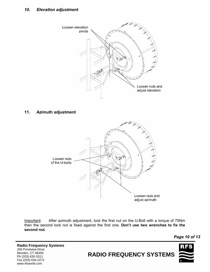
10. Elevation adjustment
11. Azimuth adjustment
Important: After azimuth adjustment, lock the first nut on the U-Bolt with a torque of 75Nm then the second lock nut is fixed against the first one. Don’t use two wrenches to fix the second nut.
Page 10 of 13
RADIO FREQUENCY SYSTEMSRadio Frequency Systems200 Pondview DriveMeriden, CT 06450Ph (203) 630-3311Fax (203) 634-2272www.rfsworld.com
12. Polarization adjustment
Loosen screws M6 and adjust polarization
13. Final Check When the installation of the antenna has been completed, it is necessary to make sure that the installation instructions have been followed in all aspects. It is especially important to check that all bolted joints are tightly locked.
Page 11 of 13
RADIO FREQUENCY SYSTEMSRadio Frequency Systems200 Pondview DriveMeriden, CT 06450Ph (203) 630-3311Fax (203) 634-2272www.rfsworld.com
Installation Paste for Threads
Installation Paste « Anti-seize »
Corrosion preventing and lubricating liquid especially for all threads of stainless steel bolts, U-bolts,spindles.
The installation paste has to be applied to allthreads of bolts and fine adjustment spindles.After this, keep the lubricated threads free of dustand dirt !
Fastener torque specifications are valid for boltswith installation paste only.
Sample: Casting-mount Sample: Steel-mount
Page 12 of 13
RADIO FREQUENCY SYSTEMSRadio Frequency Systems200 Pondview DriveMeriden, CT 06450Ph (203) 630-3311Fax (203) 634-2272www.rfsworld.com
Table of torquesfor nut and bolt connectionsValid for Microwave Parabolic Antennas
Attention: The values in the following table are valid for screws and bolts whichhave been greased according to the installation instructions.