Instructions and recommendations: Operation of Mutag BioChip 25™ page 1 of 18 Multi Umwelttechnologie AG Headquarters Zschorlauer Strasse 56 D-08280 Aue GERMANY Tel.: +49 (0) 3771 / 59 86 87 55 Fax: +49 (0) 3771 / 59 86 87 51 VAT ID No. DE220915804 Email [email protected][email protected]Web www.mutag.de www.mutag-biochip.com Managing Board Dr.-Ing. Markus Geiger Bernd Jürgen Rauch Chairman of Supervisory Board Hans-Jürgen Rutsatz Registration Court Amtsgericht Chemnitz HRB 19648 Bank Details Deutsche Bank AG Account no.: 603 001 900 Bank code: 290 700 24 IBAN: DE58 29070024 0603 0019 00 SWIFT/BIC: DEUTDEDBBRE Erzgebirgssparkasse Account no.: 360 100 9020 Bank code: 870 540 00 IBAN: DE22 87054000 360 100 9020 SWIFT/BIC: WELADED1STB Instructions and recommendations for the operation of Mutag BioChip 25™ carrier media Table of content 1. General ........................................................................................................................... 2 1.1 Operational framework conditions for a proper application and for prevention from damages.......................................................................................................................... 3 2. Appropriate carrier retention system for Mutag BioChip 25™ carriers ..................... 4 3. Secondary clarification (TSS removal after biological treatment) ............................. 5 4. Correct measuring and analysis of the biodegradation efficiency ............................ 5 4.1 Measuring the biodegradation efficiency of the MBBR tank ............................................. 5 4.2 Measuring the degradation efficiency of the complete treatment system ......................... 6 4.3 Evaluating of the efficiency of the secondary treatment stage.......................................... 6 5. Prevention from nutrient limitation .............................................................................. 6 6. Prevention from oxygen limitation ............................................................................... 7 7. Supply of agitation energy into the MBBR tank .......................................................... 7 7.1 Aerobic processes: Supply of agitation energy by process air ................................. 7 7.2 Anaerobic processes: Supply of agitation energy by mixers..................................... 7 8. Commissioning of the MBBR ....................................................................................... 8 8.1 How to open the packaging and how to fill the carrier media into the tank ....................... 8 8.2 Submerging/intermixing of the Mutag BioChip 25™ carriers .......................................... 10 8.3 Accelerating the intermixing of the Mutag BioChip 25™ carriers.................................... 12 8.4 Summary: Opening the packaging and filling the carrier media into the tank ................. 13 9. Motion studies ............................................................................................................. 14 10. Aeration system........................................................................................................... 14 11. Maintenance of the tank / Removing the carrier media from the tank ..................... 16 12. Suggestions for pilot trials ......................................................................................... 16 13. Temporary storage of the Mutag BioChip 25™ carriers ........................................... 17 14. Determination of the biomass immobilized on the Mutag BioChip 25™ surface .... 18 _
Transcript
Instructions and recommendations: Operation of Mutag BioChip 25™ page 1 of 18 Multi Umwelttechnologie AG Headquarters Zschorlauer Strasse 56 D-08280 Aue GERMANY Tel.: +49 (0) 3771 / 59 86 87 55 Fax: +49 (0) 3771 / 59 86 87 51 VAT ID No. DE220915804
for the operation of Mutag BioChip 25™ carrier media
Table of content 1. General ........................................................................................................................... 2 1.1 Operational framework conditions for a proper application and for prevention from damages .......................................................................................................................... 3 2. Appropriate carrier retention system for Mutag BioChip 25™ carriers ..................... 4 3. Secondary clarification (TSS removal after biological treatment) ............................. 5 4. Correct measuring and analysis of the biodegradation efficiency ............................ 5 4.1 Measuring the biodegradation efficiency of the MBBR tank ............................................. 5 4.2 Measuring the degradation efficiency of the complete treatment system ......................... 6 4.3 Evaluating of the efficiency of the secondary treatment stage .......................................... 6 5. Prevention from nutrient limitation .............................................................................. 6 6. Prevention from oxygen limitation ............................................................................... 7 7. Supply of agitation energy into the MBBR tank .......................................................... 7 7.1 Aerobic processes: Supply of agitation energy by process air ................................. 7 7.2 Anaerobic processes: Supply of agitation energy by mixers ..................................... 7 8. Commissioning of the MBBR ....................................................................................... 8 8.1 How to open the packaging and how to fill the carrier media into the tank ....................... 8 8.2 Submerging/intermixing of the Mutag BioChip 25™ carriers .......................................... 10 8.3 Accelerating the intermixing of the Mutag BioChip 25™ carriers .................................... 12 8.4 Summary: Opening the packaging and filling the carrier media into the tank ................. 13 9. Motion studies ............................................................................................................. 14 10. Aeration system ........................................................................................................... 14 11. Maintenance of the tank / Removing the carrier media from the tank ..................... 16 12. Suggestions for pilot trials ......................................................................................... 16 13. Temporary storage of the Mutag BioChip 25™ carriers ........................................... 17 14. Determination of the biomass immobilized on the Mutag BioChip 25™ surface .... 18
_
Umwelttechnologie AG
Instructions and recommendations: Operation of Mutag BioChip 25™ page 2 of 18
1. General The Mutag BioChip 25™ is a high-performance carrier for biofilms, made of virgin PE and exclusively intended for being used in MBBR or IFAS process for the biological treatment of water and wastewater. Using the Mutag BioChip 25™ in fixed film application results in a dramatically reduced biodegradation efficiency and his hence in no way recommended. Definitions: MBBR Abbreviation of Moving Bed Biofilm Reactor
IFAS Abbreviation of Integrated Fixed Film Activated Sludge process; means the combination of MBBR and activated sludge process in one treatment tank
Surface area Means the against mechanical influence protected active surface area provided by MBBR carrier media, which is completely available for the attachment of biofilms. The protected active surface area of the Mutag BioChip 25™ is provided in form of a detailed pore system and accounts for 4,000 m²/m³.
Biofilm Means the entirety of microorganisms (biocoenosis) colonizing the surface of the carrier media.
Substrate Means the entirety of pollutants in the wastewater, which are to be removed by the metabolism of the microorganisms within the scope of the biodegradation.
Filtered sample Wastewater sample which is initially filtered by a membrane filter (pore size of 0.45 microns) prior to measuring and analyzing any wastewater parameters. Due to the filtration, the corresponding parameters are being measured as dissolved parameters.
Limitation Limitation/reduction of the biodegradation efficiency, resulting from sub-optimal process conditions.
Retention system Equipment at the MBBR outlet, preventing any carriers from being flushed out of the tank.
Aeration system Equipment at the tank bottom for supplying process air (or technical oxygen) to the reaction tank.
N & P N (nitrogen) und P (phosphorous) are nutrients which are indispensable for the growth of biomass. N & P have to be permanently available at sufficient extent in the wastewater in order to ensure an optimal biological removal of pollutants by the microorganisms. In the case of any lack in N & P, the biodegradation efficiency is being drastically reduced, depending on the intensity of the lack in nutrients.
Umwelttechnologie AG
Instructions and recommendations: Operation of Mutag BioChip 25™ page 3 of 18
C-N-P ratio The biomass permanently re-generated due to the biodegradation of pollutants (biomass growth) is incorporating N & P as well as C (carbon) into its substance. The C:N:P-ratio in the substance of the biomass is 100:5:1 in general. Carbon is available in the wastewater in the form of COD, whereas the nutrients N & P are, at least in certain applications and in particular industrial wastewaters, not sufficiently or not at all available and have to be added (please see paragraph 5).
Virgin PE For manufacturing the Mutag BioChip 25™, only new (virgin) polyethylene is being used as raw material since it allows for a controlled adjustment of the carriers’ material density. The origin of the raw material is known whereas any negative impacts on the sensitive microorganisms (which can be caused by inhibitory substances as possibly contained in PE re-granulate) are being avoided. By this, a high process stability is ensured.
PE re-granulate In order to reduce costs in the manufacturing of “conventional“ carrier media, there is mostly used recycled PE as raw material which has been processed to granulate. The origin and former application of such re-granulates are only rarely known; hence the existence of any inhibitory substances cannot be excluded whereas the latter may have a negative impact on the sensitive biocoenoses and lead to a decrease in biodegradation efficiency and in process stability. Re-granulate can also contain further different plastics such as PP (no purity of variety). Furthermore, a certain density of the manufactured product cannot be adjusted due to the fact that the raw material density can fluctuate and vary due to the existence of different recycled substances.
1.1 Operational framework conditions for a proper application and for prevention from damages In order to ensure a trouble-free application of the Mutag BioChip 25™ and to prevent the carrier media from damage and/or even from destruction, the following points have to be adhered to:
- According to its intended purpose, the carrier material must be used only in MBBR or IFAS systems for biological treatment of water and wastewater.
- The water / wastewater must not contain any PE-disintegrating substances.
- The Mutag BioChip 25™ carrier media must not be exposed to UV radiation, ozone (O3) or high concentrations of chemicals! (Please note especially on storing the material.)
- The carrier media must be kept in permanent suspension in the water. For this reason,
agitation energy must be provided – depending on the type of the process (aerobic or anaerobic), the supply of agitation energy is effected either by means of aeration (aerobic treatment) or by means of slowly-rotating mixers (in anaerobic treatment processes).
Umwelttechnologie AG
Instructions and recommendations: Operation of Mutag BioChip 25™ page 4 of 18
- The Mutag BioChip 25™ must not get into direct contact with any devices/items/surfaces which might damage or even destroy it (such as pumps (except air lift pumps), rapidly-rotating mixers, etc.).
- The MBBR tank should be equipped with an overflow protection; otherwise the carrier
media might get lost in the case of a tank overflow.
- For retaining the carrier media in the tank, there has to be installed an appropriate carrier retention screen in the MBBR in order to prevent from a loss of carrier media and a corresponding decrease in biodegradation efficiency. For your reference, please see also paragraph 2.
- All tank outlets have to be checked and protected from any potential escape of carrier
media. The Mutag BioChip 25™ has an average material thickness of approx. 1 mm; hence all slots in the tank have to be sealed prior to filling the media into the tank.
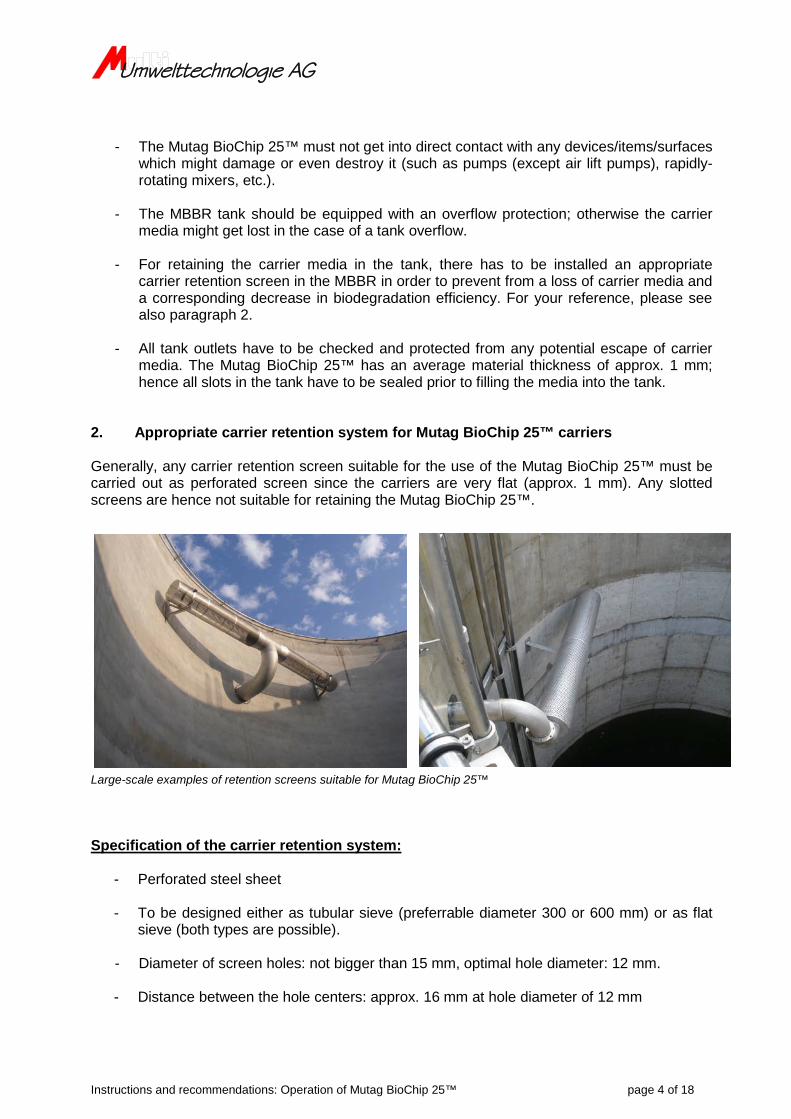
2. Appropriate carrier retention system for Mutag BioChip 25™ carriers Generally, any carrier retention screen suitable for the use of the Mutag BioChip 25™ must be carried out as perforated screen since the carriers are very flat (approx. 1 mm). Any slotted screens are hence not suitable for retaining the Mutag BioChip 25™.
Large-scale examples of retention screens suitable for Mutag BioChip 25™ Specification of the carrier retention system:
- Perforated steel sheet
- To be designed either as tubular sieve (preferrable diameter 300 or 600 mm) or as flat sieve (both types are possible).
- Diameter of screen holes: not bigger than 15 mm, optimal hole diameter: 12 mm.
- Distance between the hole centers: approx. 16 mm at hole diameter of 12 mm
Umwelttechnologie AG
Instructions and recommendations: Operation of Mutag BioChip 25™ page 5 of 18
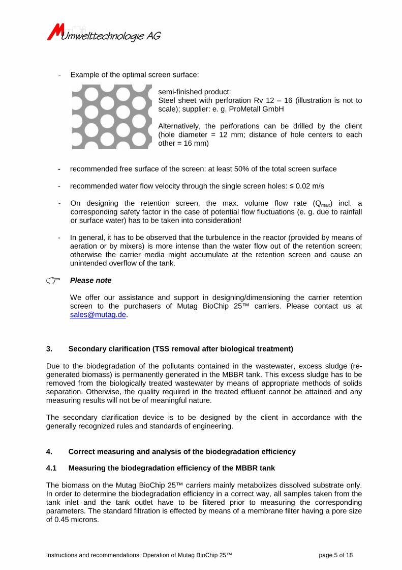
- Example of the optimal screen surface: semi-finished product: Steel sheet with perforation Rv 12 – 16 (illustration is not to
scale); supplier: e. g. ProMetall GmbH
Alternatively, the perforations can be drilled by the client (hole diameter = 12 mm; distance of hole centers to each other = 16 mm)
- recommended free surface of the screen: at least 50% of the total screen surface
- recommended water flow velocity through the single screen holes: ≤ 0.02 m/s
- On designing the retention screen, the max. volume flow rate (Qmax) incl. a corresponding safety factor in the case of potential flow fluctuations (e. g. due to rainfall or surface water) has to be taken into consideration!
- In general, it has to be observed that the turbulence in the reactor (provided by means of
aeration or by mixers) is more intense than the water flow out of the retention screen; otherwise the carrier media might accumulate at the retention screen and cause an unintended overflow of the tank.
Please note
We offer our assistance and support in designing/dimensioning the carrier retention screen to the purchasers of Mutag BioChip 25™ carriers. Please contact us at [email protected].
3. Secondary clarification (TSS removal after biological treatment) Due to the biodegradation of the pollutants contained in the wastewater, excess sludge (re-generated biomass) is permanently generated in the MBBR tank. This excess sludge has to be removed from the biologically treated wastewater by means of appropriate methods of solids separation. Otherwise, the quality required in the treated effluent cannot be attained and any measuring results will not be of meaningful nature. The secondary clarification device is to be designed by the client in accordance with the generally recognized rules and standards of engineering. 4. Correct measuring and analysis of the biodegradation efficiency 4.1 Measuring the biodegradation efficiency of the MBBR tank The biomass on the Mutag BioChip 25™ carriers mainly metabolizes dissolved substrate only. In order to determine the biodegradation efficiency in a correct way, all samples taken from the tank inlet and the tank outlet have to be filtered prior to measuring the corresponding parameters. The standard filtration is effected by means of a membrane filter having a pore size of 0.45 microns.
Instructions and recommendations: Operation of Mutag BioChip 25™ page 6 of 18
The filtration of the wastewater samples by means of a membrane filter having a pore size of 0.45 microns serves for simulating the secondary treatment stage which is installed downstream of the MBBR stage; it has to be designed in accordance with the generally recognized rules and standard of engineering and has to work properly. Any different ways of preparing the samples for measuring are not admissible for appropriately evaluating the biodegradation efficiency of the MBBR! 4.2 Measuring the degradation efficiency of the complete treatment system In order to evaluate the degradation efficiency of the complete treatment system, the relevant parameters are being measured based on the unfiltered (homogenized) samples taken from the plant inlet and the plant outlet. 4.3 Evaluating of the efficiency of the secondary treatment stage The efficiency of the secondary treatment (TSS removal after MBBR stage) can be verified by comparing the measured results of the filtered (dissolved) sample taken from the MBBR outlet on the one hand to the unfiltered (homogenized) sample taken from the outlet of the secondary treatment device on the other hand. If necessary, the secondary treatment stage has to be optimized by appropriate means. 5. Prevention from nutrient limitation The metabolism and hence the growth as well as the re-generation of biomass require the sufficient availability of nutrients. In order to ensure an optimal biodegradation efficiency of the Mutag BioChip 25™, the MBBR system must not be limited in nutrients. Under certain circumstances, it may be necessary to add the nutriens N (nitrogen) and P (phosphorous). The monitoring is effected by measuring the filtered samples from the MBBR outlet (please see also paragraph 4.1). Recommended concentrations, unless the outlet parameter requirements are not stricter:
If the concentrations should fall below the values mentioned above, the corresponding supply has to be increased, provided that the outlet parameter requirements allow for it. By this, it is ensured that the biocoenosis is sufficiently supplied with nutrients. In general, it has to be taken into consideration that the dosing of the nutrients is permanently adapted to the current flow rate (Q) and to the respective COD concentration!
Umwelttechnologie AG
Instructions and recommendations: Operation of Mutag BioChip 25™ page 7 of 18
6. Prevention from oxygen limitation In aerobic degradation processes (e. g. COD/BOD removal, nitrification), the biomass must be provided with oxygen (O2). Mostly, this is done by means of process air which is taken out of the ambient air by blowers and/or compressors. The process air is supplied to the aeration system at the bottom of the tank and is transferred into the water. The following dissolved oxygen concentrations are being recommended: Oxygen concentration in COD/BOD removal process: 2 – 4 mg/L (MBBR outlet) Oxygen concentration in nitrification process: at least 5 mg/L (MBBR outlet) 7. Supply of agitation energy into the MBBR tank The Mutag BioChip 25™ is a Moving Bed Biofilm Reactor high-performance carrier and must hence be kept in suspension in the wastewater. 7.1 Aerobic processes: Supply of agitation energy by process air In aerobic biodegradation processes, the movement of the carriers is effected by process air. The correspondingly required process air flow is at least 15 – 17 Nm³ [process air] / m² [tank footprint] / h; whereas Nm³ shall mean the abbreviation of “standard cubic meter”.
Please note:
As the circumstances may require, the process air flow required for optimally supplying the biofilms with oxygen (please see also paragraph 6.) might be higher than the air flow required for keeping the carriers in suspension. In this case, the higher value must be used for designing the process air flow. In any cases where the process air supply required for oxygenation should be significantly lower than the process air flow required for mixing, it should be checked if the installation of an additional mixer might be reasonable with regard to energy saving potential. On request, we shall be pleased to give you our advices in this matter.
7.2 Anaerobic processes: Supply of agitation energy by mixers In anaerobic biodegradation processes, the movement of the carriers has to be effected by means of slowly-rotating mixers only! The mixer to be used in each single application has to be specified by a corresponding supplier.
Umwelttechnologie AG
Instructions and recommendations: Operation of Mutag BioChip 25™ page 8 of 18
8. Commissioning of the MBBR 8.1 How to open the packaging and how to fill the carrier media into the tank Prior to adding the media into the MBBR tank, the latter must be carefully checked in order to ensure that no Mutag BioChip 25™ carriers can unintendedly leave the tank. It has to be made sure that any openings, retention screens, tank components, etc., have been constructed and mounted in a way which prevents any carrier elements from leaving the tank on unintended basis, for example through any slots or gaps which might exist. Usually, the Mutag BioChip 25™ is delivered in BigBags (net weight: each 255 kg) containing 1.5 m³ of carrier media, as shown in the pictures below.
IMPORTANT: Please note that the Mutag BioChip 25™, delivered in the original packaging of Multi Umwelttechnologie AG, is compacted bulk goods. Due to vibrations and movement occurring during transportation by road, sea or air freight, the material might become further compacted and the center of gravity of the BigBags may be dislocated into different directions. This has to be seriously taken into consideration when the BigBags are being unloaded. The BigBags have at least four holding eyelets. By using a crane + cable/chain, the BigBags can be hitched at these eyelets and be transported to the place of destination.
BigBag being transported by crane
Umwelttechnologie AG
Instructions and recommendations: Operation of Mutag BioChip 25™ page 9 of 18
The most efficient way to fill the carriers into the MBBR tank is to hang the BigBag approx. 1.5 m above the water level of the tank. Subsequently, three edges of the BigBag’s base should be cut along by using a knife, resulting in the Mutag BioChip 25™s falling into the water. At least three cuts along the three base edges are necessary due to the fact that the carriers are normally very compacted in the BigBags and might hence be prevented from falling out of the BigBag in the case that there are made less or smaller cuts.
BigBag being cut along the base edge
Mutag BioChip 25™ carriers falling out of the BigBag
Umwelttechnologie AG
Instructions and recommendations: Operation of Mutag BioChip 25™ page 10 of 18
IMPORTANT: When cutting the BigBags / when filling the Mutag BioChip 25™ carrier media into the tank, it needs to be imperatively observed that no parts of the packaging’s foil are falling into the tank. Otherwise, any parts of the foil might block the carrier retention screens, which might lead to an unintended overflow of the tank. The floating phenomenon of the “virgin”, i.e. uncolonized, carrier media - explained more in detail below in paragraph 8.2 - must be considered during filling the carrier media into the tank! Especially large carrier media volumes to be filled into tanks with a low freeboard may lead to a relatively high piling of the carrier media on the water surface. Under certain circumstances, this can result in a loss of certain quantities of carrier media due to the influence of wind and/or foam generation! (Not only with regard to the alongcoming loss of degradation efficiency, but also in terms of order and cleanliness at the WWTP, the corresponding impression towards the client has to be taken into consideration.) The unintended loss of carrier media can be prevented from by step-wise filling of the carriers, for example. 8.2 Submerging/intermixing of the Mutag BioChip 25™ carriers Initially, the Mutag BioChip 25™ without biofilm has hydrophobic characteristics at an average material density of approx. 0.95 kg/L. As a consequence, the “virgin” carriers (i.e. without biofilm) will float on the water surface after they have been filled into the MBBR tank. Once the biomass growth on the carrier increases, the Mutag BioChip 25™ becomes hydrophilic and, once fully colonized, the material density approaches the density of water in dependence from the biofilm characteristics. Consequently, the carriers will submerge and can be intermixed into the water. The following conditions are pre-requisite for an optimal submerging/intermixing of the carriers:
- sufficient water temperature - sufficient supply of substrate (sufficiently high substrate concentration) - sufficient supply of nutrients (N & P, please see also paragraph 5.) - sufficient agitation energy (either by process air or by mixer)
If the intermixing energy should be supplied in the form of process air, then the air flow rate should be higher than the minimum air flow required for agitation under normal operating conditions (please see paragraph 7.1) in order to create turbulences in the tank sufficient for submerging/intermixing the carriers. It has to be taken into consideration that the growth of the biofilms depends among others on the water temperature as well as on the process conditions. For example, nitrifying bacteria are growing much more slowly than COD-removing bacteria, whereas also the type of the wastewater (substrate concentration) has a significant impact on the growth rate of the microorganisms. Depending on the aspects mentioned directly above, it might take a few days up to several weeks until the biofilm growth is sufficient for the carrier media becoming submerged.
Umwelttechnologie AG
Instructions and recommendations: Operation of Mutag BioChip 25™ page 11 of 18
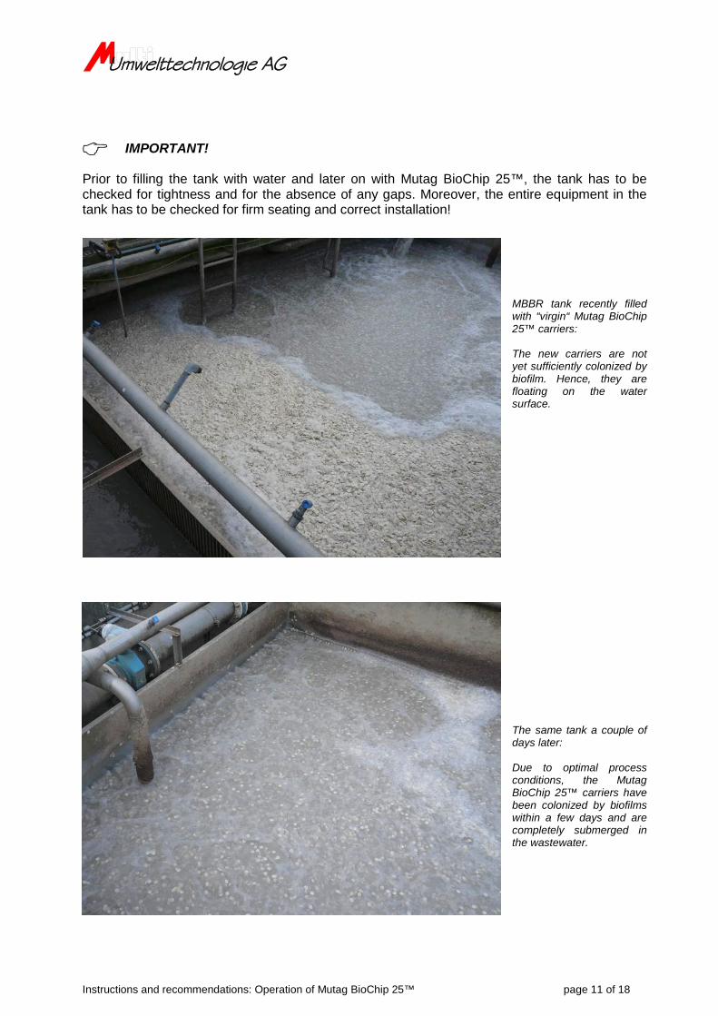
IMPORTANT! Prior to filling the tank with water and later on with Mutag BioChip 25™, the tank has to be checked for tightness and for the absence of any gaps. Moreover, the entire equipment in the tank has to be checked for firm seating and correct installation!
MBBR tank recently filled with “virgin“ Mutag BioChip 25™ carriers: The new carriers are not yet sufficiently colonized by biofilm. Hence, they are floating on the water surface.
The same tank a couple of days later: Due to optimal process conditions, the Mutag BioChip 25™ carriers have been colonized by biofilms within a few days and are completely submerged in the wastewater.
Umwelttechnologie AG
Instructions and recommendations: Operation of Mutag BioChip 25™ page 12 of 18
8.3 Accelerating the intermixing of the Mutag BioChip 25™ carriers Additional measures can help accelerate the intermixing of the carriers and the growth of biomass, respectively. Directly after filling the media, when the carriers float on the water surface, it is useful to establish a high turbulence or even a vertical circulation flow in the tank. Due to the circulation flow, the uncolonized carriers will be dragged from the water surface into the water due to the flow direction. This will accelerate the moistening of the carriers which is essential for the colonization by biomass. The establishing of such a circulation flow will work correctly only if the corresponding technical conditions are provided (e.g. several individually controllable air feed pipes; please see also the picture below). By blocking certain areas of the aeration grid, the tank will be aerated on one side only. This leads to the generation of a vertically circulating flow, in which the water flows upwards on the aerated side and downwards on the non-aerated side of the tank The picture below shows a main distribution pipe for air which is splitting up into three individually controllable air feed pipes (the fourth one is for another purpose) which are initially routed along the tank wall and subsequently across the bottom of the tank. In this particular case, membrane aerators are attached to each one of these air feed pipes. In the particular case shown below, a circulation flow can be established by blocking 1 - 2 air feed pipes.
A further additional measure suitable for accelerating the growth of biomass is to add seeding sludge. Being “conventional” activated sludge taken out of another plant treating a similar type of wastewater, the seeding sludge provides a certain pool of specialized microorganisms whose concentration in the sludge is significantly higher than their natural content in the raw wastewater and in the air. By adding seeding sludge, the growth of these wastewater-specific organisms will accelerate, provided that the sludge is taken out of another plant treating a similar type of wastewater. In the case that there should be used any seeding sludge from a plant treating a different type of wastewater, the mortality rare might increase while the advantage mentioned before will be minimized.
Main distribution pipe
Three air feed pipes leading to membrane aerators (at the tank bottom)
Air supply
Umwelttechnologie AG
Instructions and recommendations: Operation of Mutag BioChip 25™ page 13 of 18
The main points to be considered by using seeding sludge are as follows: Use only fresh activated sludge which is biologically active. Any pre-treated sludge (e.g.
from drainage systems) is inappropriate. We recommend to use activated sludge from WWTPs where a similar type of
wastewater is treated (selected microorganisms). The higher the volatile dry matter content in the seeding sludge, the higher the initial
concentration of useful microorganisms. The higher the applied seeding sludge volume, the higher the initial concentration of
useful microorganisms. In the case that the plant should be operated in continuous operation from the beginning
(continuous plant influent and effluent flows), it might be possible that several lots of seeding sludge are necessary due to flushing-out effects.
8.4 Summary: Opening the packaging and filling the carrier media into the tank The following requirements should be complied with before the filling: thorough inspection of the MBBR tank and of the retention screens installed in it; there
must not be any opening through which the Mutag BioChip 25™ carriers may possibly leave the tank
the tank has been already filled (completely or partially) with water respectively is going to be filled with water/wastewater directly after the carriers are filled in
aeration system and mixers, respectively, are fully functioning and ready for operation water / wastewater in the MBBR tank contains (at least partially) biologically usable
substrate sufficient concentration of nutrients and trace elements such as phosphorous, nitrogen,
iron, magnesium, etc., are available in the wastewater optimal water conditions for the growth of biomass in terms of parameters such as water
temperature, pH, oxygen content, etc., have been adjusted Please note during the filling: The BigBags are to be transported to the intended MBBR tank by using the holding
eyelets in conjunction with a crane. The BigBag is hung over the tank whereas the accessibility to it has to be ensured under taking into consideration the applicable safety instructions (if necessary, the executing staff is to be secured and protected by safety belt, protective helmet, etc.).
The BigBag hanging over the tank is to be cut by knife along three of its base edges The Mutag BioChip 25™ carriers will fall out of the BigBag; it has to be ensured that the
BigBag is being emptied completely. Furthermore, it has to be observed that no parts of the foil of the packaging are falling into the tank.
The initial floating of the carriers without biofilm is not unusual and has to be accepted. In the case of low freeboard; in the case of a potential overfill or carrier media loss due to foam or wind, the filling procedure has to be interrupted and to be continued later on
Under some circumstances, the following actions may help accelerate the intermixing process of the carriers and/or the initial growth of biofilms: Creating a high turbulence or circulation flow in the tank. Seeding by means of biological activated sludge.
Umwelttechnologie AG
Instructions and recommendations: Operation of Mutag BioChip 25™ page 14 of 18
9. Motion studies In the following video clips, you can see motion studies of the previous version “Mutag BioChip™” after the carriers have been sufficiently colonized by biofilms: Motion studies part 1: http://www.mutag-biochip.com/movies_1.html Motion studies part 2: http://www.mutag-biochip.com/movies_2.html Nitrification in clear water: http://www.youtube.com/watch?v=Y5i9UluIXtY 10. Aeration system Basically, the Mutag BioChip 25™ can be operated with both types of aeration systems (coarse bubble aeration as well as fine bubble aeration). Due to the better oxygen transfer into the water provided by fine bubble aeration systems, membrane aerators are rather suitable at lower water levels whereas it has to be taken into consideration that this type of aeration system is relatively failure-prone and requires a comparably high amount of maintenance. Aeration grid (pipe membranes) with five individually controllable air feed pipes
Instructions and recommendations: Operation of Mutag BioChip 25™ page 15 of 18
Contrary to fine bubble aeration, the coarse bubble aeration systems (perforated aeration pipes) are nearly maintenance-free and suitable for higher water levels. Aeration grid (perforated pipes) with individually controllable air feed pipes The air feed provided to the aeration system should be effected through multiple, individually controllable air feed pipes. This facilitates the creation of different turbulence patterns in the tank (e.g. vertically circulating turbulence in the case of one-sided air supply, please see also paragraph 8.3). In order to ensure an optimal mixing, the aeration system has to be allocated over the entire area of the tank bottom. By this, the formation of so-called “dead zones” is being avoided, in which the carriers might settle down. Please be aware that any carriers which are not in motion cannot perform optimally with regard to biodegradation and can furthermore lead to fouling effects at the tank bottom.
Aeration system allocated regularly over the entire tank bottom area.
Umwelttechnologie AG
Instructions and recommendations: Operation of Mutag BioChip 25™ page 16 of 18
11. Maintenance of the tank / Removing the carrier media from the tank During maintenance of the tank and/or the tank equipment, it might become necessary to empty the tank and/or to remove the carrier media from the latter. Emptying of the tank (carrier media remains in the tank): For this purpose, a submersible pump surrounded by a strainer can be used. The strainer prevents from the carrier media entering the pump, which might lead to damage, destruction or loss of carriers. Removing the carrier media from the tank: This might become necessary e.g. when the aeration system needs to be maintained. For this purpose, a dirt water pump which does not damage the carriers can be used. The water is pumped together with the carrier media from the MBBR tank into a second tank. After the finalization of the maintenance work, the water incl. the carriers are pumped back into the MBBR tank in the same way. Alternatively, the carrier media can be “fished” out of the MBBR tank by means of an appropriate basket. However, this method is significantly costlier in terms of labor and time. After the carriers have been completely removed from the tank, the remaining tank content can be pumped out of the MBBR. 12. Suggestions for pilot trials Please find below some suggestions for pilot trials and tests. Option no. 1: step-wise increase in carrier media quantity The trials are being started at a very low media filling degree. The filling degree is being increased on a step-wise basis (it is required to regularly measure the relevant parameters) until the required pollutant concentration is reached in the treated effluent. Please note that the maximum carrier media filling degree is 50 - 60% of the active (i.e. useable) tank volume. It has to be considered that there is maintained a certain time interval between each step of the filling degree increase; this interval must be at least long enough for making sure that the removal rates stabilize in each step. By doing so, it is ensured that the respective new-added carriers are fully colonized by biofilms and have reached 100 % of their biodegradation performance before any further “virgin” media (i.e. without biofilm) is added.
Umwelttechnologie AG
Instructions and recommendations: Operation of Mutag BioChip 25™ page 17 of 18
Option no. 2: step-wise reduction of the carrier media quantity The trials are being started at the maximally possible carrier media filling degree (max. 50 - 60% of the active tank volume). As the Mutag BioChip 25™ has a very large surface area (4,000 m2/m3), it is very likely that the actual carrier media quantity required for reaching the biodegradation target is significantly lower. The media filling degree is reduced on a step-wise basis (it is required to regularly measure the relevant parameters) until the treated effluent concentrations show an uptrend. The last filling degree at which the treated effluent parameters still remained stable corresponds to the minimum carrier quantity which is required for reaching the treatment target.
How to reach the required biodegradation rates
In the case that the biodegradation rates should remain unsatisfactory after a longer period of time, the media filling degree can be increased on a step-wise basis (please note that the process air supply for oxygenation needs to be adapted accordingly; the maximally possible carrier media filling degree is 50 - 60% of the active tank volume). In this connection, it has to be taken into account that there is maintained a certain time interval between each step of the filling degree increase; this interval must be at least long enough for making sure that the removal rates stabilize in each step. By doing so, it is ensured that the biocoenosis has adapted to the changed conditions (please see also option no. 1 mentioned above). If the biodegradation rates should be higher than actually required, the media filling degree can be reduced on step-wise basis (please see also option no. 2 mentioned above). It has of course to be made sure that the required conditions
- sufficient water temperature - sufficient supply of substrate (sufficiently high substrate concentration) - sufficient supply of nutrients (N & P, please see also paragraph 5.) - sufficient agitation energy (either by process air or by mixer)
are provided in each step of the pilot trial and are safely substantiated. 13. Temporary storage of the Mutag BioChip 25™ carriers If it should be foreseen to temporarily store the carrier media for a period exceeding 2 weeks, the storage instructions applicable for the Mutag BioChip™ must be adhered to. They can be requested by email, to be sent to [email protected].
Instructions and recommendations: Operation of Mutag BioChip 25™ page 18 of 18
14. Determination of the biomass immobilized on the Mutag BioChip 25™ surface In order to determine the biomass content (dry matter) attached to the Mutag BioChip 25™ carriers, please find below a step-wise guide:
1. Please take a carrier sample of approx 20 to 30 single Mutag BioChip 25™ elements from the MBBR tank.
2. Dry the obtained carriers over night at a temperature of max. 80°C.
3. Weigh the dried carrier elements (by means of precision scale).
4. In order to remove the biofilm from the carrier surface, please let the dried carriers
sojourn for 12 to 24 hours in a bath of 5% caustic soda (NaOH) or in laboratory cleaner.
5. Please flush the caustic soda or laboratory cleaner off the carrier elements by means of clear water. If necessary, please repeat the steps no. 4 and 5 mentioned above until the pore system of the carrier elements is completely free from biomass. In the case that caustic soda or laboratory cleaner should turn out to be insufficient for removing the biomass, you can also try to use 15% hydrochloric acid (HCl).
6. Dry the carriers again as previously described in step no. 2.
7. Please re-weigh the Mutag BioChip 25™ carriers which are dry and free from biomass.
8. Please calculate the difference from the results measured in steps no. 3 and 7. The
result indicates the weight of the biomass which was immobilized on the carriers before.
9. Please divide the result from step no. 8 by the number of carriers which underwent the aforementioned procedure. The result indicates the biomass (dry matter) in average immobilized on one single Mutag BioChip 25™.
10. Based on the carrier media quantity operated in total in the MBBR tank, please
extrapolate the result from step no. 9. Reference figures: 1 m³ of Mutag BioChip 25™ (4,000 m²) is 170 kg net. The result of the extrapolation indicates the dry matter content of the biomass immobilized on the carrier media quantity in the MBBR tank.