Page 1
Instructions for Continued Airworthiness
123-013-02
Revision 1 Page i
07/25/12
Instructions for Continued Airworthiness
Cargo Hook Kit for the
Eurocopter AS350 Series Helicopter
Part Number 200-281-03
STC SR01166SE
13915 NW 3rd Court Vancouver, Washington 98685 USA Phone: 360-546-3072 Fax: 360-546-3073 Toll Free: 800-275-0883
www.OnboardSystems.com
Page 2
Instructions for Continued Airworthiness
123-013-02
Page ii Revision 1
07/25/12
THIS PAGE INTENTIONALLY LEFT BLANK
Page 3
Instructions for Continued Airworthiness
123-013-02
Revision 1 Page iii
07/25/12
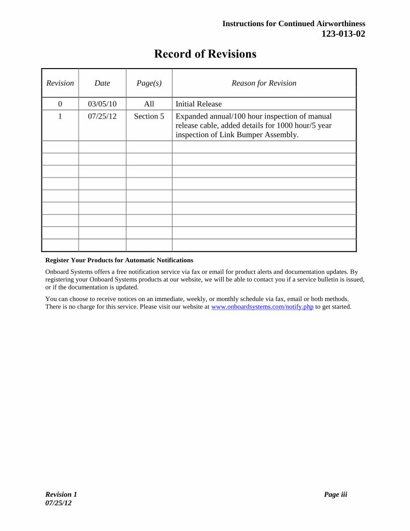
Record of Revisions
Revision
Date
Page(s)
Reason for Revision
0 03/05/10 All Initial Release
1 07/25/12 Section 5 Expanded annual/100 hour inspection of manual
release cable, added details for 1000 hour/5 year
inspection of Link Bumper Assembly.
Register Your Products for Automatic Notifications
Onboard Systems offers a free notification service via fax or email for product alerts and documentation updates. By
registering your Onboard Systems products at our website, we will be able to contact you if a service bulletin is issued,
or if the documentation is updated.
You can choose to receive notices on an immediate, weekly, or monthly schedule via fax, email or both methods.
There is no charge for this service. Please visit our website at www.onboardsystems.com/notify.php to get started.
Page 4
Instructions for Continued Airworthiness
123-013-02
Page iv Revision 1
07/25/12
THIS PAGE INTENTIONALLY LEFT BLANK
Page 5
Instructions for Continued Airworthiness
123-013-02
Revision 1 Page v
07/25/12
List of Effective Pages
Title Pages Revision
Cover i, ii Blank 1
Record of Revisions iii ,iv Blank 1
List of Effective Pages v, vi Blank 1
Table of Contents vii, viii 1
Section 0 Introduction 00-00-00 1, 2 0
Section 4 Airworthiness Limitations 04-00-00 1, 2 Blank 0
Section 5 Inspection and Overhaul Schedule 05-00-00 1 thru 6 1
Section 25 Operation Instructions 25-00-00 1 thru 11 0
Page 6
Instructions for Continued Airworthiness
123-013-02
Page vi Revision 1
07/25/12
THIS PAGE INTENTIONALLY LEFT BLANK
Page 7
Instructions for Continued Airworthiness
123-013-02
Revision 1 Page vii
07/25/12
CONTENTS Identification Title, Page
Section 0 Introduction 00-00-00 0.4 Scope, 1
0.5 Purpose, 1
0.6 Arrangement, 1
0.7 Applicability, 1
0.9 Abbreviations, 1
0.12 Precautions, 2
0.19 Distribution of Instructions for Continued Airworthiness, 2
Section 4 Airworthiness Limitations 04-00-00 4.2 No airworthiness Limitations, 1
Section 5 Inspection and Overhaul Schedule 05-00-00 5.1 Cargo Hook Kit Inspection Schedule, 1
5.2 Cargo Hook Kit Overhaul Schedule, 6
Section 25 Equipment and Furnishings 25-00-00 25.1 Cargo Hook Connector, 1
25.2 Description, 2
25.5 Component Weights, 3
25.12 Storage Instructions, 3
25.15 Trouble Shooting, 4
25.16 Component Removal, 6
25.17 Component Re-installation, 8
25.18 General Procedures Instructions-Testing, 11
Figures 5.1.1 Hook Lock Indicator, Section 5 Page 2
5.1.2 Manual Release Cable Inspection, Section 5 Page 3
5.1.3 Manual Release Cable Conditions, Section 5 Page 3
5.1.4 Link Bumper Assembly Components, Section 5 Page 4
25.1 Un-commanded cargo hook release, Section 25 Page 1
25.2.1 Primary Kit Components, Section 25 Page 2
25.2.2 Cargo Hook Overview, Section 25 Page 3
25.15.1 Cargo Hook Electrical Connector, Section 25 Page 5
25.16.1 Manual Release Cable Connection, Section 25 Page 6
25.16.2 Manual Release Cover Removal, Section 25, Page 6
25.16.3 Cargo Hook Connector, Section 25, Page 7
25.17.1 Cargo Hook Attachment Hardware, Section 25, Page 8
25.17.2 Manual Release Cable Adjustment, Section 25, Page 9
25.17.3 Manual Release Cable Connection, Section 25, Page 9
25.17.4 Manual Release Cable Rigging, Section 25, Page 10
Page 8
Instructions for Continued Airworthiness
123-013-02
Page viii Revision 1
07/25/12
CONTENTS continued
Tables 5.1.1 Link Bumper Assembly Inspection Criteria, Section 5 Page 5
25.1.1 Cargo Hook Connector, Section 25 Page 1
25.5.1 Component Weights, Section 25 Page 2
25.15.1 Trouble Shooting, Section 25 Page 4
Page 9
Instructions for Continued Airworthiness
123-013-02
Revision 0 00-00-00 Page 1
03/05/10
Section 0
Introduction 0.4 Scope
The following information is necessary to carry out the service,
maintenance, and inspection of the Cargo Hook Kit P/N 200-281-03.
Cargo Hook Kit P/N 200-281-03 is a replacement cargo hook kit (see
Section 25.2 for detailed kit description) which uses the existing
Eurocopter swing suspension and the fixed provisions including internal
electrical wiring and manual release cable. Refer to appropriate Eurocopter
maintenance documentation for those components which interface with the
P/N 200-281-03 cargo hook kit.
0.5 Purpose
The purpose of this Instructions for Continued Airworthiness (ICA)
manual is to provide the information necessary to inspect, service, and
maintain in an airworthy condition the P/N 200-281-03 Cargo Hook Kit.
0.6 Arrangement This manual contains instructions for the service, maintenance, inspection
and operation of the Cargo Hook Kit P/N 200-281-03 on Eurocopter
Model AS350 helicopters. The manual is arranged in the general order that
maintenance personnel would use to install, maintain and operate the
Cargo Hook in service.
The arrangement is:
Section 0 Introduction.
Section 4 Airworthiness limitations (None apply to this System.)
Section 5 Inspection and overhaul schedule
Section 25 Equipment and Furnishings
0.7 Applicability These Instructions for Continued Airworthiness are applicable to Cargo
Hook Kit P/N 200-281-03 (with Cargo Hook P/N 528-029-00) for the
Eurocopter AS350B3 helicopter. Refer to the appropriate Eurocopter ICA
for instructions regarding parts of the aircraft that interface with the P/N
200-281-03 system.
0.9 Abbreviations FAA Federal Aviation Administration
ICA Instructions for Continued Airworthiness
CFR Code of Federal Regulations
Page 10
Instructions for Continued Airworthiness
123-013-02
00-00-00 Page 2 Revision 0
03/05/10
0.12 Precautions
The following definitions apply to precaution flags used in this manual.
Indicates a hazardous situation which, if not
avoided, will result in death or serious injury.
Indicates a hazardous situation which, if not
avoided, could result in death or serious injury.
Indicates a hazardous situation which, if not
avoided, could result in minor or moderate injury.
Draws the reader’s attention to important or
unusual information not directly related to safety.
Used to address practices not related to personal
injury.
0.19 Distribution of Instructions for Continued Airworthiness Before performing maintenance ensure that the Instructions for Continued
Airworthiness (ICA) in your possession is the most recent revision.
Current revision levels of all manuals are posted on Onboard Systems Int'l
web site at www.onboardsystems.com. Also a Documentation Update
Service is available on the web site. Registering for this service provides
an e-mail or fax notification when a manual has been revised. Hard copies
of all manuals are available from the factory, contact the factory at 800-
275-0883 to request a copy.
Page 11
Instructions for Continued Airworthiness
123-013-02
Revision 0 04-00-00 Page 1
03/05/10
Section 4
Airworthiness Limitations
4.2 No Airworthiness Limitations
The Airworthiness Limitations section is FAA approved and
specifies maintenance required under 14 CFR §§ 43.16 and 91.403,
unless an alternative program has been FAA approved.
No airworthiness limitations are associated with this type design
change.
Page 12
Instructions for Continued Airworthiness
123-013-02
04-00-00 Page 2 Revision 0
03/05/10
THIS PAGE INTENTIONALLY LEFT BLANK
Page 13
Instructions for Continued Airworthiness
123-013-02
Revision 1 05-00-00 Page 1
07/25/12
Section 5
Inspection and Overhaul Schedule 5.1 Cargo Hook Kit Inspection Schedule
The scheduled inspection interval(s) presented below are maximums and are
not to be exceeded. If the cargo hook is subjected to unusual circumstances,
extreme environmental conditions, etc., it is the responsibility of the operator
to perform the inspections more frequently to ensure proper operation. Refer
to cargo hook component maintenance manual 122-017-00 for damage and
wear tolerances.
Annually or 100 hours of external load operations, whichever
comes first, inspect the cargo hook kit per the following.
Hours of external load operations should be
interpreted to be (1) anything is attached to the
primary cargo hook (whether or not a useful load
is being transported) and (2) the aircraft is flying.
If these conditions are NOT met, time does NOT
need to be tracked.
1. Activate the electrical system and press the Cargo Release button to
ensure the cargo hook electrical release system is operating correctly.
The cargo hook must release. Reset the cargo hook by hand after
release. If the hook does not release or re-latch, do not use the unit until
the problem is resolved.
Actuating the electrical release switch
continuously in excess of 20 seconds will cause
the cargo hook release solenoid to overheat,
possibly causing permanent damage.
2. Activate the manual release system by pulling the release lever in the
cockpit. The cargo hook must release. Reset the cargo hook by hand
after release. Verify that the hook lock indicator on the side of the hook
returns to the fully locked position (see Figure 5.1.1). If the hook does
not release or re-latch, do not use the unit until the problem is resolved.
Page 14
Instructions for Continued Airworthiness
123-013-02
05-00-00 Page 2 Revision 1
07/25/12
5.1 Cargo Hook Kit Inspection Schedule continued
In the fully locked position the hook lock
indicator must align with the lines on the manual
release cover (see Figure 5.1.1).
Figure 5.1.1 Hook Lock Indicator
3. Move the cargo hook throughout its full range of motion to ensure the
manual release cable and electrical harnesses have enough slack. The
manual release cable or electrical harnesses must not be the stops that
prevent the cargo hook from swinging freely in all directions.
4. Visually inspect for presence and security of fasteners and electrical
connections.
5. Visually inspect the cargo hook side plates and covers for damage
including cracks, gouges, and nicks (refer to the cargo hook component
maintenance manual (CMM) for damage limits).
6. Visually inspect the cargo hook load beam for damage including cracks,
wear, gouges, and nicks (refer to the cargo hook CMM for damage
limits).
Page 15
Instructions for Continued Airworthiness
123-013-02
Revision 1 05-00-00 Page 3
07/25/12
5.1 Cargo Hook Kit Inspection Schedule continued
7. Visually inspect the manual release cable for damage, paying close
attention to the flexible conduit at the area of transition to the cargo hook
end fitting (refer to Figure 5.1.2). Inspect for splitting of the outer black
conduit in this area and separation of the conduit from the steel end
fitting.
Figure 5.1.2 Manual Release Cable Inspection
Pay close attention to this area
of the manual release cable.
8. Remove the manual release cover from the cargo hook and inspect the
visible section of the inner cable for kinks or frays.
Manual release cables are wearable items and
must be replaced as condition requires. Broken or
kinked conduit, inner cable kinks (ref Figure
5.1.3), frays, or sticky operation are each cause
for immediate replacement.
Figure 5.1.3 Manual Release Cable Conditions
Kinked inner cable.
Broken or kinked conduit.
Page 16
Instructions for Continued Airworthiness
123-013-02
05-00-00 Page 4 Revision 1
07/25/12
5.1 Cargo Hook Kit Inspection Schedule continued
At cargo hook overhaul (see section 5.2 for schedule), remove the kit
components from the helicopter, disassemble, and inspect the
component parts except cargo hook per this section. Refer to CMM
122-005-00 for cargo hook overhaul instructions.
Disassemble the Link Bumper Assembly referring to the figure below. The
bushings do not need to be pressed out of the Link unless they need to be
replaced per the criteria in Table 5.1.1.
Figure 5.1.4 Link Bumper Assembly Components
Link
P/N 290-771-00
Bushing
P/N 517-052-00
Bushing
P/N 290-364-00Attach Bolt
P/N 290-775-00
Hook Bumper
P/N 290-773-00
Washer
P/N 510-183-00
Washer
P/N 510-183-00
Washer
P/N 510-174-00
Nut
P/N 510-170-00
Cotter Pin
P/N 510-178-00
Page 17
Instructions for Continued Airworthiness
123-013-02
Revision 1 05-00-00 Page 5
07/25/12
5.1 Cargo Hook Kit Inspection Schedule continued
Carefully inspect, and if necessary repair, the detail parts in accordance with the instructions in Table 5.1.1.
Table 5.1.1 Link Bumper Assembly Inspection Criteria
Component Damage Permitted without Repair
Repair Maximum Damage which Causes
Replacement
Link
P/N 290-771-00
Dents, gouges, and scratches less
than .010” deep.
Blend at 20:1 ratio, length to depth, to
provide smooth transitions.
Dents, gouges and scratches greater than .030”.
Visible cracks.
Bushing
P/N 517-052-00
These bushings have a Teflon type
film overlaid on a layer of sintered
copper. Teflon film still covers
more than 50% of the bushing wear
area.
None. If copper is visible over more than 50% of the
bushing wear area, remove and replace the
bushing.
Bumper,
P/N 290-773-00
Gouges less than .060” deep.
None. Gouges greater than .060” deep.
Attach Bolt,
P/N 290-775-00
Wear on outside diameter, diameter
greater than .495”.
None. Wear on outside diameter, diameter less than
.495”.
Visible cracks.
Bushing
P/N 290-364-00
Wear on inside diameter, diameter
less than .510”.
None. Wear on inside diameter, diameter greater than
.510”.
Page 18
Instructions for Continued Airworthiness
123-013-02
05-00-00 Page 6 Revision 1
07/25/12 08
5.2 Cargo Hook Kit Overhaul Schedule Overhaul the cargo hook in accordance with the guidelines below.
Time Between Overhaul (TBO): 1000 hours of external load operations or
5 years, whichever comes first.
Hours of external load operations should be
interpreted to be (1) anything is attached to the
primary cargo hook (whether or not a useful load
is being transported) and (2) the aircraft is flying.
If these conditions are NOT met, time does NOT
need to be tracked.
Overhaul the cargo hook per component maintenance manual 122-017-00.
Contact Onboard Systems for guidance in locating authorized overhaul
facilities.
Page 19
Instructions for Continued Airworthiness
123-013-02
Revision 0 25-00-00 Page 1
03/05/10
Section 25
Equipment and Furnishings
Un-commanded cargo hook release will happen
if the manual release cable is improperly
restrained. The cable must not be the stops that
prevent the Cargo Hook from swinging freely in
all directions. If the Cargo Hook loads cause the
hook to strain against the manual release cable
the swaged end of the cable may separate
allowing the inner cable to activate the cargo
hook manual release mechanism. The result is an
un-commanded release. Ensure that no
combination of cyclic stick or Cargo Hook
position is restrained by the manual release
cable.
Figure 25.1 Un-commanded cargo hook release
25.1 Cargo Hook Connector Listed below is the pin out for the cargo hook connector.
Table 25.1.1 Cargo Hook Connector
Pin Function
A Ground
B Positive
Page 20
Instructions for Continued Airworthiness
123-013-02
25-00-00 Page 2 Revision 0
03/05/10
25.2 Description The primary components of the 200-281-03 Cargo Hook Kit are (see Figure
25.2.1 and Table 25.2.1 for identification):
1. The Cargo Hook, which attaches to the AS350 swing suspension through
a supplied adapter link/bumper assembly.
2. A manual release cable, which interfaces with the helicopter’s existing
fixed manual release cable.
3. A bumper, which provides protection for the manual and electrical release
cables.
4. An electrical connector, which is supplied to splice into and interface
with the helicopter’s electrical release system.
Figure 25.2.1 Primary Kit Components
Table 25.2.1 Primary Kit Components
Item Part No. Description
1 232-149-00 Link Bumper Assembly
2 528-029-00 Talon LC 3.6K Cargo Hook Assembly
3 230-077-00 Connector Assembly
4 268-024-02 Manual Release Cable Assembly
A load is attached to the cargo hook by passing a load ring into the throat of
the load beam and pushing the ring against the upper portion of the load beam
throat (see Figure 25.2.2), which will initiate the hook to close. In the closed
position, a latch engages the load beam and latches it in this position. A load
release can be initiated by three different methods. Normal release is achieved
by pilot actuation of a push-button switch in the cockpit. When the push-
button switch is pressed, it energizes the solenoid in the cargo hook, and the
solenoid opens the latch in the internal mechanism.
Page 21
Instructions for Continued Airworthiness
123-013-02
Revision 0 25-00-00 Page 3
03/05/10
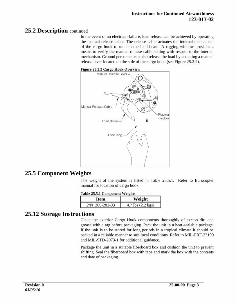
25.2 Description continued In the event of an electrical failure, load release can be achieved by operating
the manual release cable. The release cable actuates the internal mechanism
of the cargo hook to unlatch the load beam. A rigging window provides a
means to verify the manual release cable setting with respect to the internal
mechanism. Ground personnel can also release the load by actuating a manual
release lever located on the side of the cargo hook (see Figure 25.2.2).
Figure 25.2.2 Cargo Hook Overview
Manual Release Lever
Load Beam
Manual Release Cable
Load Ring
Rigging
window
25.5 Component Weights The weight of the system is listed in Table 25.5.1. Refer to Eurocopter
manual for location of cargo hook.
Table 25.5.1 Component Weights
Item Weight
P/N 200-281-03 4.7 lbs (2.2 kgs)
25.12 Storage Instructions Clean the exterior Cargo Hook components thoroughly of excess dirt and
grease with a rag before packaging. Pack the unit in a heat-sealable package.
If the unit is to be stored for long periods in a tropical climate it should be
packed in a reliable manner to suit local conditions. Refer to MIL-PRF-23199
and MIL-STD-2073-1 for additional guidance.
Package the unit in a suitable fiberboard box and cushion the unit to prevent
shifting. Seal the fiberboard box with tape and mark the box with the contents
and date of packaging.
Page 22
Instructions for Continued Airworthiness
123-013-02
25-00-00 Page 4 Revision 0
03/05/10
25.15 Troubleshooting Table 25.15.1 is provided with the intention of isolating the cause of malfunctions within the
system. Sections 25.16 and 25.17 include instructions for removing and replacing defective
components. Refer to the appropriate Eurocopter maintenance for guidance on procedures
relating to Eurocopter parts that interface with the cargo hook and adapter cable.
Table 25.15.1 Troubleshooting
MALFUNCTION PROBABLE CAUSE CORRECTIVE ACTION Cargo hook does not operate
electrically, manual cable release
operates normally.
Open electrical circuit, faulty
wiring, fuse, switch or solenoid.
Disconnect cable from electrical
connector on cargo hook.
Using multi-meter, check for 3.0 to 4.0
ohms between pins A and B of electrical
connector (see note 1). If open indication
is obtained, remove and replace cargo
hook (see sections 25.16 and 25.17).
Cargo hook does not operate
electrically or manually.
Defective internal mechanism
Remove and replace cargo hook (see
sections 25.16 and 25.17) or repair per
cargo hook service manual 122-017-00.
Cargo hook operates electrically,
but not manually.
Defective manual release cable.
Defective manual release system.
Check manual release cable and cable
connection to cargo hook (remove and
replace manual release cable per sections
25.16 and 25.17).
Remove and replace cargo hook (see
sections 25.16 and 25.17) or repair per
cargo hook service manual 122-017-00.
Load beam fails to re-latch after
being reset.
Defective latch mechanism.
Remove and replace cargo hook (see
sections 25.16 and 25.17) or repair per
cargo hook service manual 122-017-00.
Cargo hook manual release cable
pull-off force exceeds 8 Lbs. (at
the hook).
Friction in internal mechanism. Check operation of unit using manual
release lever. Remove and replace cargo
hook (see sections 25.16 and 25.17) or
repair per cargo hook service manual
122-017-00.
Visibly loose fasteners or missing
locking pins
Visibly loose fasteners or missing
locking pins.
Re-torque and re-install locking pins per
installation instructions.
Failure to open or re-lock
properly
Failure to open or re-lock
properly.
Remove and replace cargo hook (see
sections 25.16 and 25.17) or repair per
cargo hook service manual 122-017-00.
Fuse opens when cargo hook is
energized.
Short in the system, faulty
wiring, fuse or solenoid.
Check for shorts to ground. Check
solenoid resistance (see note 1).
Page 23
Instructions for Continued Airworthiness
123-013-02
Revision 0 25-00-00 Page 5
03/05/10
Notes:
1. Checking resistance at pins A and B.
Check for 3.0 to 4.0 ohms between pins A and B of electrical connector located on the cargo
hook (see below).
Figure 25.15.1 Cargo Hook Electrical Connector
SECTION A-A
SCALE: 3:1
Page 24
Instructions for Continued Airworthiness
123-013-02
25-00-00 Page 6 Revision 0
03/05/10
25.16 Component Removal
Cargo Hook Removal 1. Remove manual release cover by removing 2 screws.
2. Loosen jam nut and unthread the manual release cable from the Cargo
Hook.
3. Disconnect the electrical release connector at the cargo hook.
4. Remove the cotter pin P/N 510-178-00 from the Attach Bolt P/N 290-
775-00 (reference Figure 25.17.1).
5. Remove the castellated nut P/N 510-170-00 from the Attach Bolt.
6. Remove Attach Bolt and all washers.
7. Remove cargo hook.
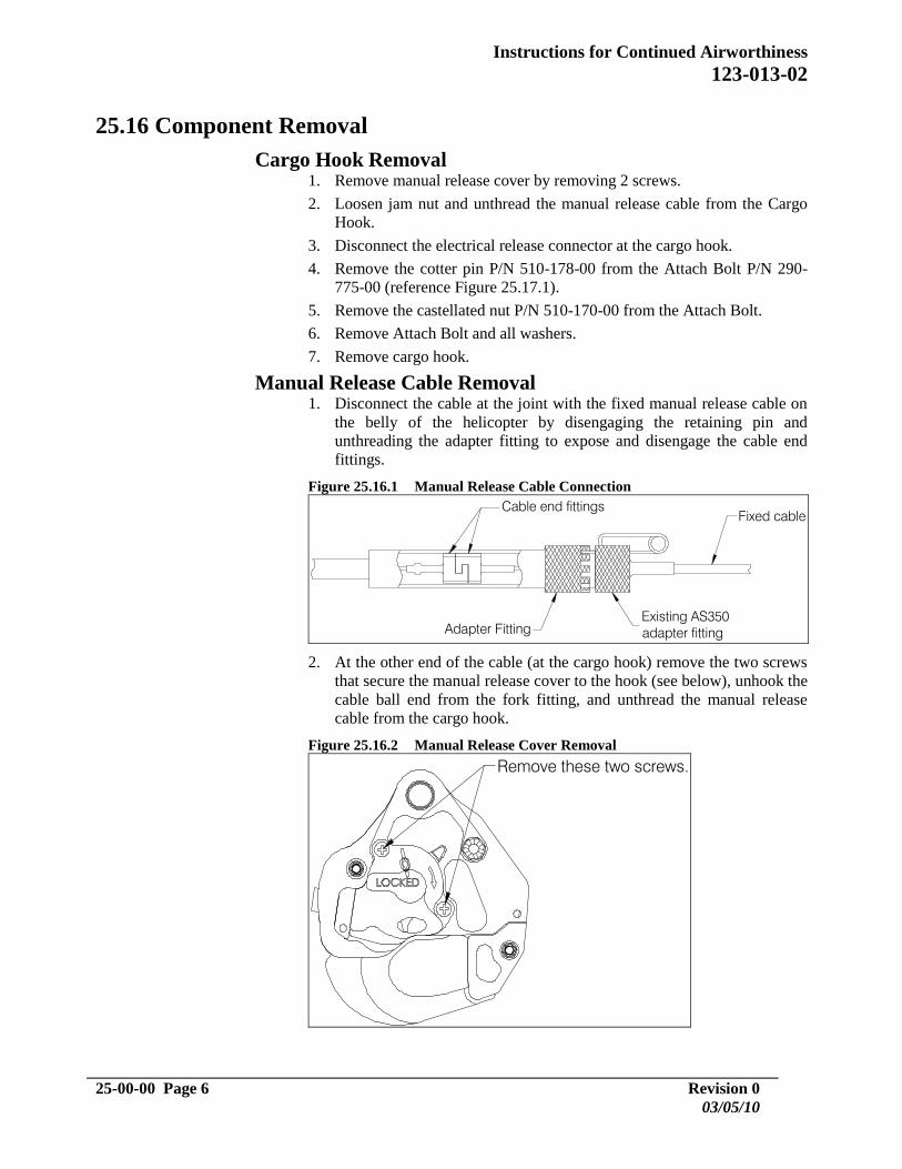
Manual Release Cable Removal 1. Disconnect the cable at the joint with the fixed manual release cable on
the belly of the helicopter by disengaging the retaining pin and
unthreading the adapter fitting to expose and disengage the cable end
fittings.
Figure 25.16.1 Manual Release Cable Connection
Existing AS350
adapter fittingAdapter Fitting
Cable end fittings
Fixed cable
2. At the other end of the cable (at the cargo hook) remove the two screws
that secure the manual release cover to the hook (see below), unhook the
cable ball end from the fork fitting, and unthread the manual release
cable from the cargo hook.
Figure 25.16.2 Manual Release Cover Removal
Remove these two screws.
Page 25
Instructions for Continued Airworthiness
123-013-02
Revision 0 25-00-00 Page 7
03/05/10
25.16 Component Removal continued
Electrical Connector Removal The kit supplied connector (P/N 230-077-00) replaces the connector on the
end of the Eurocopter external harness.
1. Loosen the set screw on the backshell.
2. Unthread the backshell from the connector base to expose the solder
contacts and de-solder the wires.
3. Cut safety wire and unthread the connector base from the cargo hook
connector.
Figure 25.16.3 Cargo Hook Connector
Electrical Connector
(P/N 230-077-00)
Page 26
Instructions for Continued Airworthiness
123-013-02
25-00-00 Page 8 Revision 0
03/05/10
25.17 Component Re-installation
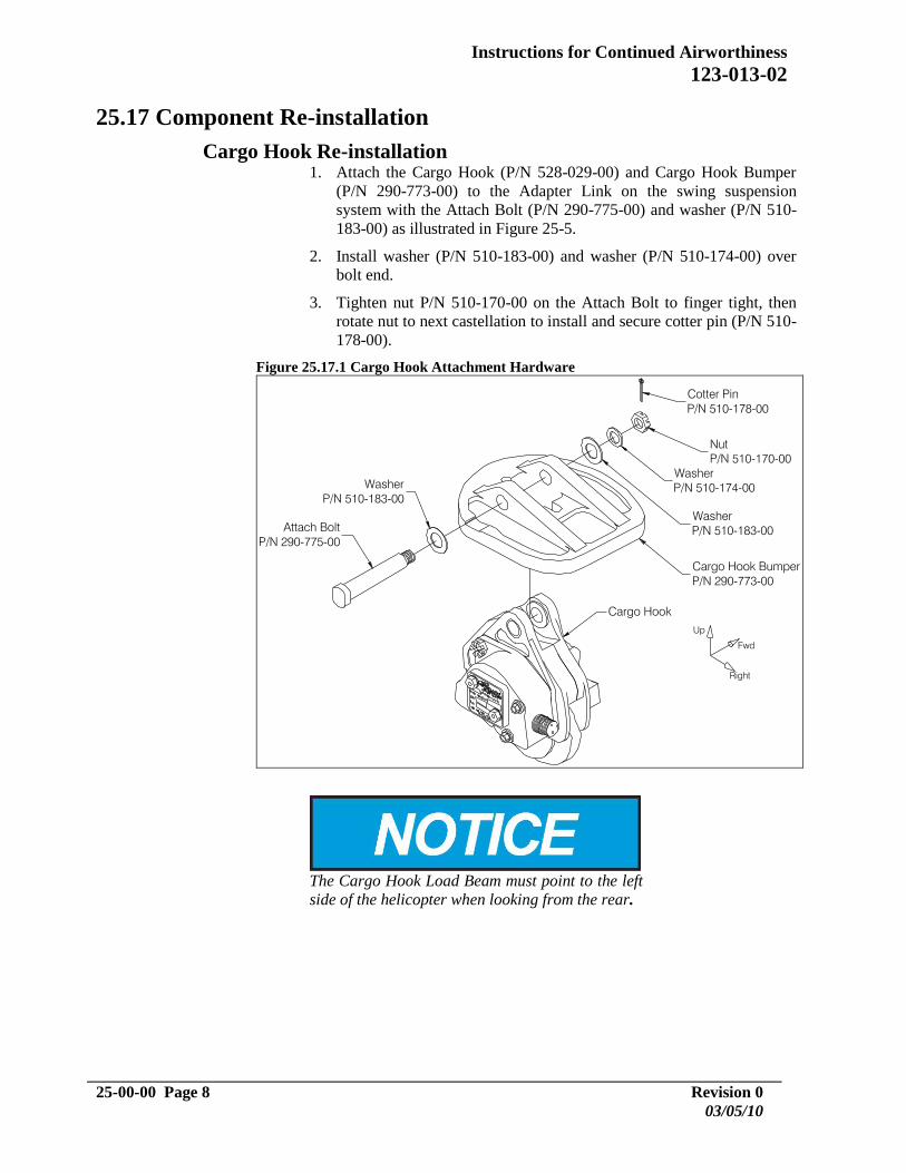
Cargo Hook Re-installation 1. Attach the Cargo Hook (P/N 528-029-00) and Cargo Hook Bumper
(P/N 290-773-00) to the Adapter Link on the swing suspension
system with the Attach Bolt (P/N 290-775-00) and washer (P/N 510-
183-00) as illustrated in Figure 25-5.
2. Install washer (P/N 510-183-00) and washer (P/N 510-174-00) over
bolt end.
3. Tighten nut P/N 510-170-00 on the Attach Bolt to finger tight, then
rotate nut to next castellation to install and secure cotter pin (P/N 510-
178-00).
Figure 25.17.1 Cargo Hook Attachment Hardware
Washer
P/N 510-183-00
Fwd
Right
Up
The Cargo Hook Load Beam must point to the left
side of the helicopter when looking from the rear.
Page 27
Instructions for Continued Airworthiness
123-013-02
Revision 0 25-00-00 Page 9
03/05/10
25.17 Component Re-installation, continued
Connect the manual release cable (P/N 268-024-02) to the cargo hook per
the following instructions:
1. Remove the manual release cover from the cargo hook (see Figure
25.16.2).
2. Thread the fitting at the end of the manual release cable into the manual
release boss on the hook side plate until the threads protrude
approximately .125 inches beyond the boss and secure with jam nut (as
shown in Figure 25.17.2). Leave the cover off of the cargo hook until
the other end of the release cable is connected, in order to verify proper
setting.
Figure 25.17.2 Manual Release Cable Adjustment
3. Connect the other end of the release cable to the fixed section of the
existing AS350 manual release cable by mating the cable end fittings
together as shown below. Slide the Adapter Fitting forward and thread
it onto the existing AS350 fitting, and engage a castellation on the
Adapter Fitting with the retaining pin to lock it in place.
Figure 25.17.3 Manual Release Cable Connection
boss
jam nut
Approx. .125 in. (3.2mm)
Manual Release Cable fitting
EXISTING AS350B3
ADAPTER FITTINGADAPTER FITTING
CABLE END FITTINGS
FIXED CABLE
Page 28
Instructions for Continued Airworthiness
123-013-02
25-00-00 Page 10 Revision 0
3/05/10
25.17 Component Re-installation, continued
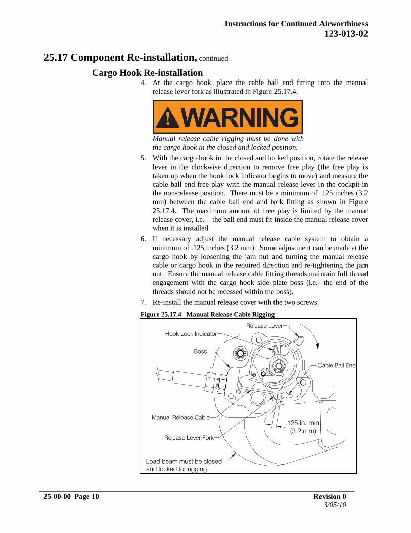
Cargo Hook Re-installation 4. At the cargo hook, place the cable ball end fitting into the manual
release lever fork as illustrated in Figure 25.17.4.
Manual release cable rigging must be done with
the cargo hook in the closed and locked position.
5. With the cargo hook in the closed and locked position, rotate the release
lever in the clockwise direction to remove free play (the free play is
taken up when the hook lock indicator begins to move) and measure the
cable ball end free play with the manual release lever in the cockpit in
the non-release position. There must be a minimum of .125 inches (3.2
mm) between the cable ball end and fork fitting as shown in Figure
25.17.4. The maximum amount of free play is limited by the manual
release cover, i.e. – the ball end must fit inside the manual release cover
when it is installed.
6. If necessary adjust the manual release cable system to obtain a
minimum of .125 inches (3.2 mm). Some adjustment can be made at the
cargo hook by loosening the jam nut and turning the manual release
cable or cargo hook in the required direction and re-tightening the jam
nut. Ensure the manual release cable fitting threads maintain full thread
engagement with the cargo hook side plate boss (i.e.- the end of the
threads should not be recessed within the boss).
7. Re-install the manual release cover with the two screws.
Figure 25.17.4 Manual Release Cable Rigging
Hook Lock Indicator
Release Lever
Manual Release Cable
Release Lever Fork
Cable Ball End
.125 in. min.
(3.2 mm)
Load beam must be closed
and locked for rigging.
Boss
Page 29
Instructions for Continued Airworthiness
123-013-02
Revision 0 25-00-00 Page 11
03/05/10
25.18 General Procedural Instructions-Testing After re-installation, perform the following:
1. Activate the electrical system and press the Cargo Release button to
ensure the cargo hook electrical release system is operating correctly.
The cargo hook must release. Reset the cargo hook by hand after
release. If the hook does not release or re-latch, do not use the unit
until the problem is resolved.
Actuating the electrical release switch
continuously in excess of 20 seconds will cause the
cargo hook release solenoid to overheat, possibly
causing permanent damage.
2. Activate the manual release system by pulling the release lever in the
cockpit. The cargo hook must release. Reset the cargo hook by hand
after release. Verify that the hook lock indicator on the side of the
hook returns to the fully locked position. If the hook does not release
or re-latch, do not use the unit until the problem is resolved.
In the fully locked position the hook lock
indicator must align with the lines on the manual
release cover (see Figure 5.1.1).
3. Swing the installed cargo hook and the suspension to ensure that the
manual release cable and the electrical release harness have enough
slack to allow full swing of the cargo hook and suspension assembly
without straining or damaging the cable or harness. The cable or
harness must not be the stops that prevent the Cargo Hook from
swinging freely in all directions.