40
December, 1998 949-1311-1 INSTRUCTIONS FOR THE 32A SERIES 1/32 DIN MICROPROCESSOR BASED TEMPERATURE /PROCESS CONTROL

December, 1998 Page 1 of 40 949-1311-1
INSTRUCTIONS FOR THE 32A SERIES 1/32 DINMICROPROCESSOR BASED
TEMPERATURE /PROCESS CONTROL

949-1311-1 Page 2 of 40 December, 1998
CONTENTS
INSTALLATION....................................................................................... 4WIRING ................................................................................................... 5
Wiring for Optional Inputs and Outputs ............................................. 6Wiring for 4 to 20mA Transmitter inputs ........................................... 7
FRONT PANEL KEY FUNCTIONS ......................................................... 8NOTATION CONVENTIONS FOR THE MENUS ................................. 10THE HOME DISPLAY ........................................................................... 10PROGRAMMING AND OPERATION FOR RAMP / SOAK FEATURE 11
Theory of Operation ........................................................................ 11Program Setup ................................................................................ 11Ramp / Soak Operation .................................................................. 13
AUTO / MANUAL OPERATION ............................................................. 13OPERATION OF SELF TUNE® FUNCTION ........................................ 14
Theory of Operation ........................................................................ 14Program Setup and Operation ........................................................ 15
OPERATION AND PROGRAMMING OF OPTIONS ............................ 15Options 924, 926, 928, Analog Remote Set Point .......................... 15Option 934, 936, Isolated Analog Retransmission. ......................... 16Option 948, 2-Stage Set Point. ....................................................... 16Option 992, Serial Communication. ................................................ 17
CHANGING PROGRAMMING FOR SET POINT 2 AND ALARM ........ 18FACTORY DEFAULT PROCEDURE .................................................... 18ALARM TYPE AND ACTION ................................................................ 19MENU SELECTIONS ........................................................................... 20PRIMARY MENU .................................................................................. 20SECONDARY MENU ............................................................................ 21SECURE MENU .................................................................................... 28SPECIFICATIONS ................................................................................ 35DIAGNOSTIC ERROR MESSAGES..................................................... 37DIAGNOSTIC ERROR MESSAGES..................................................... 38DIMENSIONS ....................................................................................... 40
© 1997, Love Controls Division, Dwyer Instruments, Incorporated. All rights reserved. Noportion may be copied without the express written consent of Love Controls.

December, 1998 Page 3 of 40 949-1311-1
GETTING STARTED
1. Install the control as described on page 4.
2. Wire your control following the instructions on page 5. If you are usinga two-wire transmitter as an input, see the drawing and instructions onpage 7. Option wiring instructions are on page 6. Option descriptionsare on page 4, and specific instructions start on page 16.
3. Most controls do not need many (if any) program changes to work onyour process. For best results when programming changes arenecessary, make all the necessary changes in the Secure Menu (page28) before making changes to the Secondary Menu (page 21). If errormessages occur, check the Diagnostic Error Messages on page 37 and38 for help.
Take the example of a Model 32A010 that comes from the factoryprogrammed for type J thermocouples. Suppose for this example you wishto change the input to type K and limit the set point range between 0° and1000° C.
First, enter the Secure menu as instructed on page 5. Press the INDEX keyuntil the display shows Inp and press the DOWN ARROW until the displayshows CA. Don't forget to press the ENTER key to retain your setting.
Next, press the INDEX key to display Unit . Press the DOWN ARROW untilthe display shows C. Press ENTER.
Next, press the INDEX key until SPL is displayed (pass the dPt and InPtselections). Press the UP ARROW until the display shows 0. PressENTER.
Finally, press INDEX key to display SPH. Press the DOWN ARROW untilthe display shows 1000. Press ENTER.
The necessary program changes are now complete. After 60 seconds thedisplay will switch back to the temperature reading. If you want to returnfaster, press the UP ARROW and ENTER keys (at the same time) and thenpress the DOWN ARROW and INDEX keys ( again at the same time). Thiswill 'back out' of the menu and immediately display the temperature reading.
If you want to use Self Tune®, Auto/Manual, or the Ramp/Soak Program-mer features, see the special sections on these items. Page numbers forthese are in the Contents section on the previous page.

949-1311-1 Page 4 of 40 December, 1998
MODEL IDENTIFICATION
Model 3 2 A — —
AlarmProgramming0 = No1 = Yes
Output 11 = SSR2 = 5 VDC3 = Relay
5 = Current8 = DC SSR
Output 20 = None1 = SSR2 = 5 VDC
3 = Relay8 = DC SSR
Options
Options:924 Analog Remote Set Point, 0 to 10 VDC.926 Analog Remote Set Point, 4 to 20 mADC.928 Analog Remote Set Point, 0 to 10,000 ohms.934 Analog Retransmission of Process Variable or Set Variable, 4 to 20
mAdc.936 Analog Retransmission of Process Variable or Set Variable, 0 to 10
Vdc.948 2-Stage Set Point. One of two pre-set set point values can be
implemented via contact closure.992 RS-485 Serial Communications. Allows remote computer to read
and write all control parameters.9502 12 - 24 Vdc/Vac 50-400Hz power supply (control operates on low
voltage equipment).Note: Only Option 9502 may be combined with another option. No other
options may be combined.
INSTALLATION
Mount the instrument in a location that will not be subject to excessivetemperature, shock, or vibration. All models are designed for mounting in anenclosed panel.
Select the position desired for the instrument on the panel. If more than oneinstrument is required, maintain the minimum of spacing requirements asshown on the drawing opposite. Closer spacing will structurally weaken thepanel, and invalidate the IP66, UL type 4 rating of the panel.
It is not necessary to remove the control chassis fromthe housing for installation. If the control chassis isremoved from the housing, you must follow industrystandard practice for control and protection againstElectro-Static Discharge (ESD). Failure to exercisegood ESD practices may cause damage to the control.

December, 1998 Page 5 of 40 949-1311-1
Prepare the panel by cutting and deburring the required opening(s).
From the front of the panel, slide the housing through the cutout. Thehousing gasket should be flat against the housing flange before installing.
From the rear of the panel slide the mounting collar over the housing. Holdthe housing with one hand and using the other hand, push the collar evenlyagainst the panel until the spring loops are slightly compressed. Theratchets will hold the mounting collar and housing in place. To remove,gently lift the ratchets and slide a piece of heavy paper or mylar sheet undereach ratchet (a business card works well). Slide the collar off of the housing.
WIRINGDo not run thermocouple or other class 2 wiring in the same conduit aspower leads. Use only the type of thermocouple or RTD probe for whichthe control has been programmed. Maintain separation between wiring ofsensor, auxiliary in or out, and other wiring. See the "Secure Menu" for inputselection.
For thermocouple input always use extension leads of the same typedesignated for your thermocouple.
For supply connections use No. 18 AWG wires rated for at least 75°C. Usecopper conductors only. All line voltage output circuits must have acommon disconnect and be connected to the same pole of the disconnect.
Input wiring for thermocouple, current, and RTD; and output wiring forcurrent, DC SSR, and 5 VDC is rated CLASS 2.
45 + 0.6(1.772 + 0.02)
22.2 + 0.3(0.874 + 0.012)
20.5(0.807)
25.4(1.00)
949-1311-1 Page 6 of 40 December, 1998
Wiring for Optional Inputs and Outputs
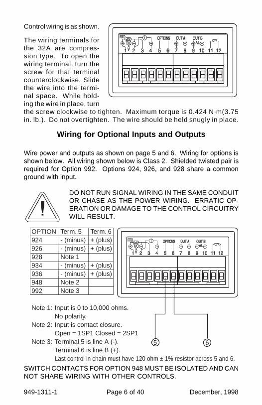
Wire power and outputs as shown on page 5 and 6. Wiring for options isshown below. All wiring shown below is Class 2. Shielded twisted pair isrequired for Option 992. Options 924, 926, and 928 share a commonground with input.
DO NOT RUN SIGNAL WIRING IN THE SAME CONDUITOR CHASE AS THE POWER WIRING. ERRATIC OP-ERATION OR DAMAGE TO THE CONTROL CIRCUITRYWILL RESULT.
The wiring terminals forthe 32A are compres-sion type. To open thewiring terminal, turn thescrew for that terminalcounterclockwise. Slidethe wire into the termi-nal space. While hold-ing the wire in place, turnthe screw clockwise to tighten. Maximum torque is 0.424 N·m(3.75in. lb.). Do not overtighten. The wire should be held snugly in place.
5 6
OPTION924926928934936948992
Note 1: Input is 0 to 10,000 ohms.No polarity.
Note 2: Input is contact closure.Open = 1SP1 Closed = 2SP1
Note 3: Terminal 5 is line A (-).Terminal 6 is line B (+).Last control in chain must have 120 ohm ± 1% resistor across 5 and 6.
Term. 5- (minus)- (minus)Note 1- (minus)- (minus)Note 2Note 3
Term. 6+ (plus)+ (plus)
+ (plus)+ (plus)
SWITCH CONTACTS FOR OPTION 948 MUST BE ISOLATED AND CANNOT SHARE WIRING WITH OTHER CONTROLS.
Control wiring is as shown.

December, 1998 Page 7 of 40 949-1311-1
Wiring for 4 to 20mA Transmitter inputs
Wire power and outputs as shown above. Two-wire transmitters wire asshown below.
For three or four wire transmitters follow the wiring instructions providedwith your transmitter.
DO NOT WIRE THE 24 VOLT POWER SUPPLY ACROSSTHE INPUT OF THE CONTROL. DAMAGE TO THE CON-TROL INPUT CIRCUITRY WILL RESULT.
External Power Supply
24 Vdc
+ -
+ -
Transmitter

949-1311-1 Page 8 of 40 December, 1998
FRONT PANEL KEY FUNCTIONS
Set Point 1 Lamp Process Display
Set Point 2 Lamp °F Indicator
Alarm Lamp °C Indicator
Manual Indicator Percent Lamp
Set Point Display Hold Lamp
The decimal point flashes when Self-Tune is operating.
Keys are illuminated when pressed. Key functions are as follows:
INDEX: Pressing the INDEX key advances the display to the nextmenu item. May also be used in conjunction with other keys as notedbelow.
UP ARROW: Increments a value, changes a menu item, orselects the item to ON. The maximum value obtainable is 9999regardless of decimal point placement.
DOWN ARROW: Decrements a value, changes a menu item, orselects the item to OFF. The minimum value obtainable is -1999regardless of decimal point placement.
ENTER: Pressing ENTER stores the value or the item changed. Ifnot pressed, the previously stored value or item will be retained. Thedisplay will flash once when ENTER is pressed.
UP ARROW & ENTER: Pressing these keys simultaneously brings upthe secondary menu starting at the alarm, tune, or cycle item (dependingon programming). Pressing these keys for 5 seconds will bring up thesecure menu.
INDEX & DOWN ARROW: Pressing these keys simultaneously will allowbacking up one menu item, or if at the first menu item they will cause thedisplay to return to the primary menu. If an alarm condition has occurred,these keys may be used to reset the alarm. To reset an alarm press and holdboth keys for three seconds.
INDEX & ENTER: Pressing these keys simultaneously and holding themfor 5 seconds allows recovery from the various error messages. Thefollowing menu items will be reset:
ALiH: Alarm inhibit OPEn InP: Input error message
bAd InP: Input error message CHEC CAL: Check calibration error
Correct the problems associated with the above conditions beforeusing these reset keys. More than one error could be present. Caution isadvised since several items are reset at one time.
While in the Primary or Secondary Menu, if no key is pressed for a periodof 30 seconds, the display will return to the HOME position displaying the
December, 1998 Page 9 of 40 949-1311-1
temperature value. While in the Secure Menu, if no key is pressed for aperiod of 60 seconds, the display will return to the HOME position displayingthe temperature value. Outputs are disabled (turned off) when the SecureMenu is active.
NOTE: To move to the Primary Menu quickly from any other menu, pressthe UP ARROW & ENTER keys followed by pressing the INDEX & DOWNARROW keys.
SECURITY LEVEL SELECTION
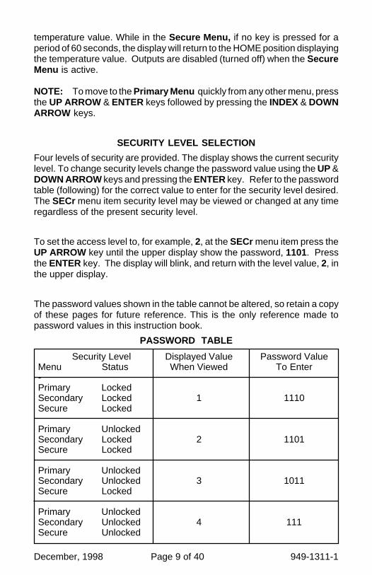
Four levels of security are provided. The display shows the current securitylevel. To change security levels change the password value using the UP &DOWN ARROW keys and pressing the ENTER key. Refer to the passwordtable (following) for the correct value to enter for the security level desired.The SECr menu item security level may be viewed or changed at any timeregardless of the present security level.
To set the access level to, for example, 2, at the SECr menu item press theUP ARROW key until the upper display show the password, 1101. Pressthe ENTER key. The display will blink, and return with the level value, 2, inthe upper display.
The password values shown in the table cannot be altered, so retain a copyof these pages for future reference. This is the only reference made topassword values in this instruction book.
PASSWORD TABLE
Displayed ValueWhen Viewed
1
2
3
4
Security LevelMenu Status-Primary LockedSecondary LockedSecure Locked
Primary UnlockedSecondary LockedSecure Locked
Primary UnlockedSecondary UnlockedSecure Locked
Primary UnlockedSecondary UnlockedSecure Unlocked
Password ValueTo Enter
1110
1101
1011
111

949-1311-1 Page 10 of 40 December, 1998
NOTATION CONVENTIONS FOR THE MENUSBecause of the number of features available in this control, information isincluded that may not apply to your specific control. All usable features areincluded in this book, but may not be used in your process. To increaseclarity the following conventions are used:
1. Certain features, Menu Items, and functions shown in this book may ormay not appear on your control, depending on other Menu Item selections.At various places in the Menus there are notes identifying Menu Items that"control" or "direct" other menu items. If you are looking for a particularmenu item and can't find it, check the menu item that is its "control" forproper setting.
2. The "#" symbol is used in two ways. It is used inside a group ofcharacters to indicate which set point function (SP1 or SP2) is beingaffected. It is also used before a group of characters of a menu item toindicate that there may be more than one selection or value for that menuitem. This is used for certain repeated items such as in the Ramp/SoakProgram section.
3. Features that apply only to Options will be printed in Italics.
THE HOME DISPLAY
The home display is the normal display while the control is operating. If noerrors or functions are active, the HOME display will indicate the ProcessVariable (the temperature, pressure, flow, RH, etc., that is being measured)on the top display and the Set Variable (Set Point 1) on the bottom.
Items that can change the HOME display are the Auto/Manual function, theProg function, the PctO function, and any error message. Description ofthese special displays follow.
If Auto/Manual is enabled, the Manual indicator lights, and the home displayis changed. The upper display continues to show the Process Variable(PV), but the lower display changes to show the percentage of output intenths of a percent to 99.9% (0.0 to 99.9), or 100 if 100%. The display digitto the right of the number shows a flashing letter o to indicate that the valuedisplayed is no longer the SV, but percent output. The SP2 output isindicated by the use of an overline on the letter õ. Access to the SP2 valueis done by the INDEX key. See Auto/Manual Operation on Page 13 forfurther information.
If Prog is turned On, the HOME display changes the SV display from SP1to the Present Set Variable as calculated by the Ramp/Soak Programmerfunction. See Programming and Operation for Ramp/Soak Feature belowfor more information.
December, 1998 Page 11 of 40 949-1311-1
PROGRAMMING AND OPERATION FOR RAMP / SOAKFEATURE
The ramp / soak feature offers a great deal of flexibility by allowing changesin the set point to be made over a predetermined period of time. Soak(dwell) times can be programmed, and the alarm output relay can beprogrammed to open or close during any of the segments.
Theory of OperationThe 32A Series controls offer a very simple approach to programming aramp. Rather than requiring the operator to calculate an approach rate(usually in degrees per minute), the 32A does the calculation internally.Thus, the operator only needs to program the target set point and the timedesired to reach that point. When the ramp segment is executed by thecontrol, it calculates the ramp required to move the process from thestarting value (current PV) to the desired value (programmed SP) in thetime allowed.
Soaks (or dwells) are ramp segments where the target set point is the sameas the beginning process value. This allows for multistage ramps withoutwasting intermediate soak steps. Care must be taken, however, that theprocess does actually reach the soak value before the soak time starts. Ifnot, the next segment will calculate a slope from the starting PV to the targetSP. Depending on your process requirements, this difference may beimportant. Make sure to test any program for desired results before runningproduction material.
Do not operate Self Tune while a ramp function is operating. Theramp function will prevent the Self Tune from operating properly.Make sure that all tuning is set up before operating Ramp / Soak.
Program Setup
All of the programming for the Ramp / Soak function is done in theSecondary Menu. You may wish to work out your program on paper beforegoing into the programmer menu sequence.
If PctO (Secondary Menu) is turned On, the lower display changes to showthe active percentage of output as required to maintain SP1. The displayis similar to the Auto/Manual display above, except that the letter indicatorsdo not flash, and the output is displayed in whole percentages of output, notin tenths of a percent. If the control has both SP1 and SP2, the lower displaywill alternate between the SP1 percent output and the SP2 percent output.
Error messages are listed on Page 37 and 38.
949-1311-1 Page 12 of 40 December, 1998
In the Secondary Menu INDEX to Prog and make sure that Prog is set toOFF.
INDEX to PSEt and turn On.
Skip the StAt setting (this is discussed later) and press INDEX to 1ti .
The following items repeat in the following order: 1ti , 1SP, 1AL (if alarm isprogrammed as an event), 2ti , 2SP, 2AL , . . . , 16ti , 16SP, 16AL . To avoidrepetition each item will only be described once.
Set 1ti to the amount of time you want for the first ramp. This value is intime units (determined by the tbAS menu item) from 0 to 9999. PressINDEX
Set 1SP to the target value desired for the first ramp. This value is in actualunits just like SP1. If the control is programmed for temperature, then theSP displays are in temperature. If the control is programmed for some otherengineering unit, the SP is set in that unit.
Press INDEX to continue. If Alarm is programmed as an event, then 1ALwill appear. If you wish the Alarm contact to function for this segment, set1AL for On. If not, set for OFF. Press INDEX. If Alarm is not programmedas an event, then 1AL will not appear. If 1AL is set to On, the Alarmfunction will be active for the entire period as set in 1ti above.
Complete setting the segment times (2ti ... 16ti ), segment set points (2SP... 16SP), and event alarm (2AL ... 16AL ) if it exists.
For unneeded or unused segments set the segment times (2ti ... 16ti ) to0, and set the segment set points (2SP ... 16SP) to the same value as thelast active set point. Event alarms may be set to indicate "end of run" asyou feel necessary.
The last menu item for the ramp / soak function is PEnd . PEnd determineswhat the control does when the program has ended. You may choose tohave the program repeat (LooP ), Hold the last set point (16SP), revert tothe local SP1, or turn the outputs off (OoFF).
It is important to remember that if you want the program to repeat, you mustallow the process to return to the same condition that existed when theprogram first started. Remember that the ramp function calculates theslope by drawing a line from the beginning PV to the ramp target set point.If the PV at the end of the program is different than the PV at the initial start,the ramp will calculate differently.

December, 1998 Page 13 of 40 949-1311-1
Ramp / Soak Operation
When you wish to start the program, enter the Secondary Menu and set theProg menu item to On. Return to the HOME position by waiting for thedisplay to time out or by pressing the UP ARROW / ENTER keys and thenthe DOWN ARROW / INDEX keys.
The home display will read as it normally does. The HOLD indicator overthe RUN / HOLD key will be lit. To start the program press INDEX to displayProg . Press the UP ARROW key to select run and press ENTER. TheHOLD indicator will go out, and the program will start.
To suspend the program at any time, INDEX to Prog , press the DOWNARROW key to display HOLd , and press ENTER. To resume, INDEX toProg , press the UP ARROW to select run , and press ENTER.
Entering the AUTO / MANUAL mode will also suspend the programoperation. The difference is that AUTO / MANUAL also puts the control intomanual mode. See Auto / Manual Operation below.
The function of the Primary Menu will change depending on the setting of theStAt menu item in the Secondary Menu. If StAt is OFF then the Primary Menuis not changed.
If the StAt menu item is set to On, then the Primary Menu has threeadditional information items added before SP1 appears. The first INDEXitem, ####/ ti , displays the time remaining in the current segment. The nextINDEX item, ####/##ti , displays the total time for the active segment(1ti ...16ti ). The third INDEX item, ####/##SP, displays the segment setvalue (1SP...16SP). The next INDEX press resumes the normal PrimaryMenu
AUTO / MANUAL OPERATION
The AUTO / MANUAL function allows you to manually adjust the output ofthe control. This is normally used during process setup or start up. It canalso be used for troubleshooting. To switch from AUTO to MANUAL pressINDEX to Auto . Press the UP ARROW to select OFF and press ENTER.The MANual indicator will light and the lower display will change from normalto showing the actual output in percent. The value will be the actualpercentage of output that was active when the key was pressed. This isusually known as "bumpless transfer".
If you wish to change the output while in manual, press the UP ARROW orDOWN ARROW keys to change the value, and press ENTER to retain it. It
949-1311-1 Page 14 of 40 December, 1998
is important to remember that the value of the display can be read as 0 to100% of the full control output, or 0 to 100% of the range between S1OL andS1OH or S2OL and S2OH. If APct is set for rEAL , a reading of 50% inMANUAL represents 10 mA. If APCt is set for AdJ , then 50% in MANUALwill represent the mid point in output between S1OL and S1OH. (AssumingS1OL is 20 and S1OH is 100 [4 to 20 mA], 50% will represent 12 mA.)
To return to AUTOmatic control, press the ENTER until Auto is displayed.Press the DOWN ARROW key to On, and press ENTER. The MANualindicator will go out, and the set point will take over. If you want bumplesstransfer back to AUTO, while in manual, slowly change the percentage ofoutput until the process variable matches (or at least is close) to the set point.The further away the PV is from the set point, the greater the "bump" or upsetthere will be in the output.
OPERATION OF SELF TUNE® FUNCTION
Self Tune® allows automatic selection of the necessary parameters toachieve best control operation from your 32A Series control. If you are usingthe control output as a simple on-off function (Out1 set for OnOF), none ofthe following will apply.
Theory of Operation
The Self Tune function calculates the Pb1, rES, and rtE parameters under thePID tunE selection, and the Fbnd and FrtE parameters, as shown in theSecondary Menu . These values are determined by measuring the responseof the process connected to the control. When Self Tune is started, the controltemporarily acts as an on-off control. While in this mode the control measuresthe overshoot and undershoot of the process, and the period of the process (thetime from peak value to the next peak value). These measurements arecollected over a period that lasts three periods of overshoot and undershoot.The data collected over this time is then compared and calculated into final PIDand Fuzzy Logic values. The effect of Fuzzy Logic on the process is stillcontrolled by the Fint (fuzzy intensity) setting. If Fint is 0, the Fbnd and FrtEwill be calculated, but will have no effect. The calculations for the PID valuesare the same as used in the standard Ziegler - Nichols equations that have beenrecognized as standard for decades.
The only modification to the application of the Ziegler - Nichols equations iscontrolled by the dFAC menu item. This menu item controls the amount of rate(derivative) that is applied. A dFAC setting of 3 (factory default) or less allowsfor less damping. A dFAC setting of 4 allows for critical damping as set forthin Ziegler - Nichols. A dFAC setting of 5 or more allows over damping of theprocess.

December, 1998 Page 15 of 40 949-1311-1
Program Setup and Operation
In the secondary menu set tunE to SELF. Skip LErn and check to makesure that dFAC is set to the desired value. Back up to LErn and set to YES.The control will begin the Self Tune function. While the Self Tune functionis active, the right hand decimal point on the lower display will blink. WhenSelf Tune is complete, the blinking will stop.
After Self Tune is complete, the tunE setting automatically switches to PID.This allows examination and / or modification of the values calculated. Werecommend that you do not change the calculated values unless you havea firm understanding of the parameters involved and their function. For moreinformation on PID tuning, please contact your supplier.
OPERATION AND PROGRAMMING OF OPTIONS
Options 924, 926, 928, Analog Remote Set PointThe analog remote set point allows the control set point to be determined byan outside analog signal. The signal may be 0 to 10 VDC (Option 924), 0(or 4) to 20 mADC (Option 926), or 0 to 10,000 Ohms (Option 928).
Wire the input as shown on page 6.
To set up the analog remote set point, first determine the scale range thatthe analog signal will represent. The maximum span is 11,998 degrees orcounts. In the Secure Menu set rSCL for the scale value that will berepresented by the low end of the analog signal (0 Volts, 0 mA, 0 Ohms). SetrSCH for the scale value that will be represented by the high end of theanalog signal (10 Volts, 20 mA, 10,000 Ohms).
If you require a suppressed scale or input, you may use the followingequations to determine the proper settings for rSCL and rSCH.
K = (Highest desired scale reading - Lowest desired scale reading) /(Maximum desired analog signal - Minimum desired analog signal).rSCH = ((Maximum possible analog signal- Maximum desired analog signal)* K) + Highest desired analog reading.rSCL = Lowest desired scale reading - ((Minimum desired analog signal) * K).
Operation is simple. Make sure that a valid analog signal is available to thecontrol. In the Secondary Menu set the rSPt to On. The REM indicator on thefront of the control will turn on. When the control returns to the HOME position,the displayed SV will be the value supplied from the analog remote signal. Ifthe analog remote signal fails or goes out of range of the SPL or SPH settings,the control will revert to the internal SP1 (or #SP1), and flash the error message

949-1311-1 Page 16 of 40 December, 1998
CHEC rSPt . If SPL or SPH are set outside of rSCL or rSCH then the error willbe suppressed, and the control will attempt to work with the remote value.
To clear the error message, change rSPt to OFF.
Option 934, 936, Isolated Analog Retransmission.
The analog retransmission option allows the Process Variable or the SetVariable to be sent as an analog signal to an external device. The signal maybe either 0 to 10 VDC (Option 936) or 0 (or 4) to 20 mADC (Option 934). Theoutput may be changed in the field from one to the other by the toggle switchlocated on the top printed circuit board.
Wire the output as shown on page 6.
To set up the analog retransmission, first determine the scale range that theanalog signal will represent. The maximum scale is 9999°F, 5530°C, or9999 counts. In the Secondary Menu set POL for the scale value that willbe represented by the low end of the analog signal (0 Volts or 0 mA). SetPOH for the scale value that will be represented by the high end of the analogsignal (10 Volts or 20 mA).
If you require a suppressed scale or output, you may use the followingequations to determine the proper settings for POL and POH.
K = (Highest desired scale reading - Lowest desired scale reading) /(Maximum desired analog signal - Minimum desired analog signal).POH = ((Maximum possible analog output - Maximum desired analog signal)* K) + Highest desired analog reading.POL = Lowest desired scale reading - ((Minimum desired analog output) * K).
Next select whether you want the retransmission signal to follow the ProcessVariable or the Set Variable. Usually the Process Variable is sent to recordersor other data acquisition devices. Usually the Set Variable is sent to othercontrols to be used as an analog remote set point. If you want the analogretransmission signal to follow the PV, in the Secondary Menu set POSr to InP.If you want the analog retransmission signal to follow the SV, set POSr to SPt.
Operation is automatic. There are no further programming steps required.
Option 948, 2-Stage Set Point.
The 2-stage set point option allows two different values to be used for SP1 andall of the values associated with the tunE menu items. The control will switchto a given stage when an external contact is made or opened across the

December, 1998 Page 17 of 40 949-1311-1
appropriate terminals at the rear of the control (when SPSA, Set Point SwitchAction, is set for remote, rE), or when the stage is selected from the SecondaryMenu, SP (when SPSA is set for Int). When the state of a contact changes(or the stage number is changed in the Secondary Menu), the values in use arestored and the previously stored values for the new stage are used.
Wire the input as shown on page 6.
Usually the control is configured for external switching of the stages. In thiscase, the operation is usually automatic, selected by the external switchesdriven by the machine logic. If it is necessary to program the stages in advance,you may select the stage to modify with the SP menu item. When SP ischanged while the SPSA is set for rE, the selected stage is displayed formodification, but only used when the appropriate contact is made.
Option 992, Serial Communication.
The serial communications option allows the control to be written to and readfrom a remote computer or other similar digital device. Communication isallowed either through a RS-485 (Option 992) port.
Wire the communication lines as shown on Page 6. Wiring for the RS-485 isrun from control to control in a daisy chain fashion with a termination resistor(120 ohms) across the transmit and receive terminals of the last control in thechain.
Select the control address and communication baud rate with the Addr andbAUd menu items in the Secure Menu. THE BAUD RATE AND ADDRESSMENU ITEMS WILL TAKE EFFECT ON THE NEXT POWER UP OF THECONTROL. BE SURE TO POWER CYCLE THE CONTROL BEFOREUSING THE NEW BAUD RATE AND ADDRESS.
In operation, you have the option of preventing a write command from the hostcomputer. To prevent the host from writing to the control change the LOrEmenu item in the Secondary Menu to LOC. To allow the host to writecommands to the control set LOrE to rE. (The host does have the ability tochange the LOrE state, but it is not automatic.)
If your system depends on constant reading or writing to and from the host, youmay wish to set the No Activity Timer (nAt ) to monitor the addressing of thecontrol. When the LOrE is set to rE and the nAt is set to any value other thanOff, the control will expect to be addressed on a regular basis. If the controlis not addressed in the time set by the value of nAt , then the control will displaythe error message CHEC LOrE . To clear the message set LOrE to LOC.
949-1311-1 Page 18 of 40 December, 1998
CHANGING PROGRAMMING FOR SET POINT 2 AND ALARM
Either Set Point 2 or the Alarm function as the second output of the 32A. Theordering code determines whether the second output operates as a secondset point or alarm.
When the 32A second output is programmed as Cont rol, SP2 appears in thePrimary Menu and the appropriate SP2 related menu items appeat in theSecondary and Secure Menus. When the 32A second output is pro-grammed as ALarm, the alarm related menu items appear in the Secondaryand Secure Menus.
If you have a control with a second output and wish to change the functionof the second output from ALarm to Cont rol (or vice versa) use the FactoryDefault procedure.
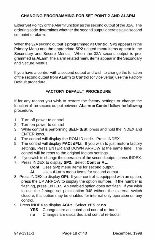
FACTORY DEFAULT PROCEDURE
If for any reason you wish to restore the factory settings or change thefunction of the second output between ALarm or Cont rol follow the followingprocedure.
1. Turn off power to control2. Turn on power to control3. While control is performing SELF tESt , press and hold the INDEX and
ENTER keys.4. The control will display the ROM ID code. Press INDEX.5. The control will display FACt dFLt . If you wish to just restore factory
settings, Press ENTER and DOWN ARROW at the same time. Thecontrol will be reset to the original factory settings.
6. If you wish to change the operation of the second output, press INDEX.7. Press INDEX to display SP2. Select Cont or AL .
Cont Uses SP2 menu items for second output.AL Uses ALarm menu items for second output.
8. Press INDEX to display OPt. If your control is equipped with an option,press the UP ARROW to display the option number. If the number isflashing, press ENTER. An enabled option does not flash. If you wishto use the 2-stage set point option 948 without the external switchclosure, this option may be enabled for internal only operation on anycontrol.
9. Press INDEX to display ACPt . Select YES or no .YES Changes are accepted and control re-boots.no Changes are discarded and control re-boots.

December, 1998 Page 19 of 40 949-1311-1
ALARM TYPE AND ACTION
Caution: In any critical application where failure couldcause expensive product loss or endanger personalsafety, a redundant limit controller is required.
The 32A Series allows Set Point 1 (and Set Point 2 is equipped) to operateas limit or alarm type outputs. This function is available on all outputs exceptthe proportional current (output type 5). To enable a set point output to actas an alarm or limit, Out1 (for SP1) or Out2 (for SP2, if equipped) should beset for OnOf .
When Out1 and / or Out2 are set to OnOF, then the alarm function menuitems will appear in the Secure Menu for the selected set point(s).
If the Alarm Programming code in the model number is set to 1, then set point2 is pre-programmed as an alarm. If the alarm Programming code in themodel number is set to 0 and the last number of the model number is not 0then the second set point is pre-programmed as a cooling output. Thisprogramming may be changed in the field with the Factory Default procedureon the previous page..
When setting SP2 value (S2t = AbS ) or the ALLO and ALHi values (ALt =AbS ) for an absolute alarm, simply set the value at which the alarm is tooccur.
When setting SP2 value (S2t = dE) or the ALLO and ALHi values (ALt =dE) for a deviation alarm, set the difference in value from the Set Point 1(SP1) desired. For example if a low alarm is required to be 5 degrees belowthe SP1, then set SP2 or ALLO to -5. If a high alarm is required 20 degreesabove the SP1, then set SP2 or ALHI to +20. If SP1 is changed, the alarm(SP2, ALLO , ALHI ) will continue to hold the same relationship as originallyset.
When Set Point Power Interrupt (S#Pi) or Alarm Power Interrupt (ALPi ), isprogrammed ON and Set Point Reset (S#rE) or Alarm Reset (ALrE ), isprogrammed for Hold , the alarm will automatically reset after a power failureand on subsequent power restoration if no alarm condition is present.
If Set Point Inhibit (S#iH) or Alarm Inhibit (ALiH ), is selected ON, an alarmcondition is suspended upon power up until the process value passesthrough the alarm set point once. Alarm inhibit can be restored as if a powerup took place by pressing both the INDEX and ENTER keys for 5 seconds.

949-1311-1 Page 20 of 40 December, 1998
MENU SELECTIONS
PRIMARY MENUPress INDEX to advance to the next menu item. Press UP ARROW orDOWN ARROW to change the value in the display. Press ENTER to retainthe value.
If StAt (Secondary Menu ) is On, the three program status menu items willappear.
ti Time remaining for current segment.
##ti Total run time for segment ##.
##SP Target Set Point for segment ##.
If StAt (Secondary Menu ) is OFF, the Primary menu operates as follows:
#SP1 (Option 948, 2-Stage Set Point) orSP1 Set Point 1 Adjust, Control Point 1.
SP2 Set Point 2 Adjust (if equipped), Control Point 2.
Auto Auto/Manual Station, Select On or OFF.On Output operation is automatic (normal operation).OFF Output is controlled manually.See Page 13 for operation of Auto/Manual Station Feature.
If Prog is OFF in the Secondary Menu, Prog (below) will not appear.
Prog Ramp/Soak Programmer Run/Hols function, Select run or HoLd .run Ramp/Soak Programmer is in operation.HoLd Ramp/Soak Programmer is on hold.
Warning : Resetting a high set point inhibit will notcause an alarm to occur if the Process Value does notfirst drop below the high set point value. Do not use theSet Point Inhibit feature if a hazard is created by thisaction. Be sure to test all combinations of high and lowset point inhibit actions before placing control intooperation.

December, 1998 Page 21 of 40 949-1311-1
SECONDARY MENUHold UP ARROW & ENTER. Press INDEX to advance to the next menuitem. Press UP ARROW or DOWN ARROW to change the value in thedisplay. Press ENTER to retain the value.
If the control is not equipped with alarm, or if the alarm functions (AL ) areturned OFF or programmed as event (Eunt ), ALLO and ALHi will notappear.
ALLo Alarm Low: The Low Alarm point is usually set below the Set Point.May not appear depending on AL setting in Secure Menu .
ALHi Alarm High: The High Alarm Point is usually set above the SetPoint. May not appear depending on AL setting in Secure Menu .
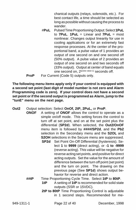
Out1 Output selection: Select OnOf, 1tP, 1PuL, or ProP .ONOF A setting of ONOF allows the control to operate as a
simple on/off mode. This setting forces the control toturn off at set point, and on at the set point plus thedifferential (SP_d). When selected, the Out1/OnOFmenu item is followed by ####/SP1d, and the tunE, Pb,rES, OFS, rtE, and ArUP selections in the Secondarymenu and the S1OL and S1OH selections in the Securemenu are suppressed.SP_d Set Point On-Off Differential (hysteresis). Se-
lect 1 to 9999 (direct acting), or -1 to -9999(reverse acting). This value will be negative forreverse acting set points, and positive for directacting outputs. Set the value for the amount ofdifference between the turn off point (set point)and the turn on point. The following drawingshows output behavior for reverse and directaction.
##tP Time Proportioning Cycle Time. Select 1tP to 80tP.1tP A setting of 1tP is recommended for solid state
outputs (SSR or 15VDC).2tP to 80tP Time Proportioning Control is adjustable
in 1 second steps. Recommended for me-
949-1311-1 Page 22 of 40 December, 1998
chanical outputs (relays, solenoids, etc.). Forbest contact life, a time should be selected aslong as possible without causing the process towander.
#PuL Pulsed Time Proportioning Output: Select 1PuLto 7PuL . 1PuL = Linear and 7PuL = mostnonlinear. Changes output linearity for use incooling applications or for an extremely fastresponse processes. At the center of the pro-portional band, a pulse value of 1 provides anoutput of one second on and one second off(50% output). A pulse value of 2 provides anoutput of one second on and two seconds off(33% output). Output at center of band equalsone second on, 2(pulse value-1) seconds off.
ProP For Current (Code 5) outputs only.
The following menu items apply only if your control is equipped witha second set point (last digit of model number is not zero and AlarmProgramming code is zero). If your control does not have a secondset point or if the second output is programmed as Alarm, jump to the"tunE" menu on the next page.
Out2 Output selection: Select OnOf, 2tP, 2PuL, or ProP .ONOF A setting of ONOF allows the control to operate as a
simple on/off mode. This setting forces the control toturn off at set point, and on at the set point plus thedifferential (SP2d). When selected, the Out2/OnOFmenu item is followed by ####/SP2d, and the Pb2selection in the Secondary menu and the S2OL andS2OH selections in the Secure menu are suppressed.SP2d Set Point On-Off Differential (hysteresis). Se-
lect 1 to 9999 (direct acting), or -1 to -9999(reverse acting). This value will be negative forreverse acting set points, and positive for directacting outputs. Set the value for the amount ofdifference between the turn off point (set point)and the turn on point. The drawing on theprevious page (See SP1d) shows output be-havior for reverse and direct action.
##tP Time Proportioning Cycle Time. Select 1tP to 80tP.1tP A setting of 1tP is recommended for solid state
outputs (SSR or 15VDC).2tP to 80tP Time Proportioning Control is adjustable
in 1 second steps. Recommended for me-

December, 1998 Page 23 of 40 949-1311-1
chanical outputs (relays, solenoids, etc.). Forbest contact life, a time should be selected aslong as possible without causing the process towander.
#PuL Pulsed Time Proportioning Output: Select 1PuLto 7PuL . 1PuL = Linear and 7PuL = mostnonlinear. Changes output linearity for use incooling applications or for an extremely fastresponse processes. At the center of the pro-portional band, a pulse value of 1 provides anoutput of one second on and one second off(50% output). A pulse value of 2 provides anoutput of one second on and two seconds off(33% output). Output at center of band equalsone second on, 2(pulse value-1) seconds off.
SP (Option 948, 2-Stage Set Point) Active Set Point Stage. Select1SP1 or 2SP1. (See Page 17 for more detail.)1SP1 Set Menu Items to display Stage 1 for view and change
access. If SPSA is set for Int , 1SP1 is made active.2SP1 Set Menu Items to display Stage 2 for view and change
access. If SPSA is set for Int, 2SP1 is made active.
#SP1 (Option 948, 2-Stage Set Point) Adjust Control Point 1 for Stageselected above.
Note: The menu items for tunE (below) are modified when Option 948 isin use. When Option 948 is active the menu items are preceeded with thestage number selected in SP above. The stage number is noted here withthe # sign. When the 2 Stage Set Point option (948) is active, each stagehas its own set of tunE parameters.
#tun (Option 948, 2-Stage Set Point) ortunE Tuning Choice: Select SELF, Pid, SLO, nor, or FASt.
SELF The Controller will evaluate the Process and select thePID values to maintain good control. Active for SP1only.LErn Select YES or no
YES Start Learning the Process. After theprocess has been learned the menuitem will revert to no .
no Learning will stay in present mode.dFAC Damping factor, Select OFF, 1 to 7. Sets the

949-1311-1 Page 24 of 40 December, 1998
ratio of Rate to Reset for the SELF tunE mode.7 = most Rate. Factory set to 3. For a fastresponse process the value should be lowered(less Rate). For a slower process the valueshould be increased (more Rate).
Pid Manually adjust the PID values. PID control consists ofthree basic parameters, Proportional Band (Gain), Re-set Time (Integral), and Rate Time (Derivative).#Pb1 (Option 948, 2-Stage Set Point) orPb1 Proportional Band (Bandwidth). Select 1 to
9999 °F, °C, or counts.Pb2 Proportional Band (Bandwidth). Select 1 to
9999 °F, °C, or counts. Appears only if controlis equipped with second set point and Out2 isNOT selected as ONOF.
#rES (Option 948, 2-Stage Set Point) orrES Automatic Reset Time. Select OFF, 0.1 to 99.9
minutes. Select OFF to switch to OFS.#OFS (Option 948, 2-Stage Set Point) orOFS Manual Offset Correction Select OFF, 0.1 to
99.9%. Select OFF to switch to rES.#rtE (Option 948, 2-Stage Set Point) orrtE Rate Time. Select OFF, 0.01 to 99.99 minutes,
Derivative.SLO PID values are preset for a slow response process.nor PID values are preset for a normal response process.FASt PID values are preset for a fast response process.
Pid2 Linkage of PID parameters between SP1 and SP2: Select On orOFF.On Applies SP1 rEs , rtE , Fbnd , and FrtE terms to SP2 for
heat/cool applications.OFF SP2 functions without rEs , rtE , Fbnd and FrtE .Does not appear if not equipped with second output or if secondoutput is programmed as alarm.
ArUP Anti- Reset Windup Feature: Select On or OFF.On When ArUP is On the accumulated Reset Offset value
will be cleared to 0% when the process input is not withinthe Proportional Band.
OFF When ArUP is OFF, the accumulated Reset OffsetValue is retained in memory when the process input isnot within the Proportional Band.
December, 1998 Page 25 of 40 949-1311-1
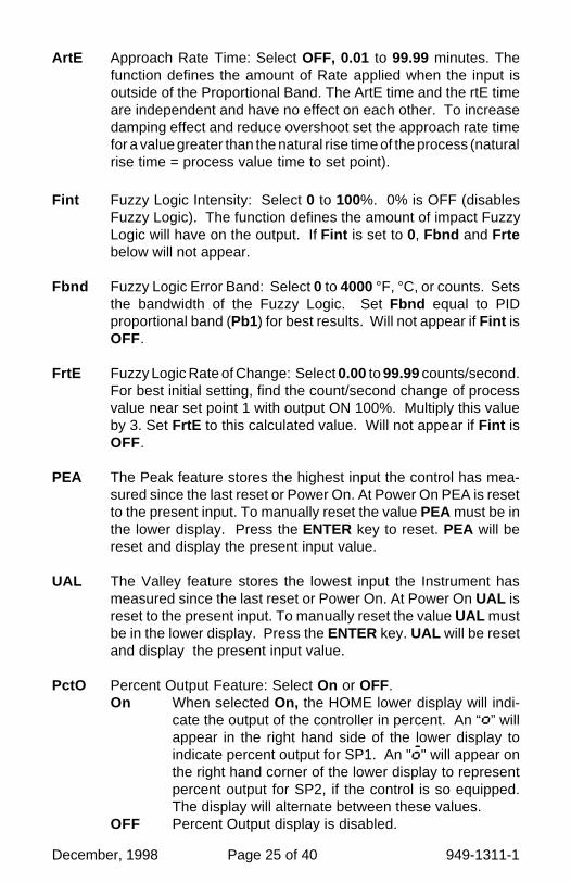
ArtE Approach Rate Time: Select OFF, 0.01 to 99.99 minutes. Thefunction defines the amount of Rate applied when the input isoutside of the Proportional Band. The ArtE time and the rtE timeare independent and have no effect on each other. To increasedamping effect and reduce overshoot set the approach rate timefor a value greater than the natural rise time of the process (naturalrise time = process value time to set point).
Fint Fuzzy Logic Intensity: Select 0 to 100%. 0% is OFF (disablesFuzzy Logic). The function defines the amount of impact FuzzyLogic will have on the output. If Fint is set to 0, Fbnd and Frtebelow will not appear.
Fbnd Fuzzy Logic Error Band: Select 0 to 4000 °F, °C, or counts. Setsthe bandwidth of the Fuzzy Logic. Set Fbnd equal to PIDproportional band (Pb1) for best results. Will not appear if Fint isOFF.
FrtE Fuzzy Logic Rate of Change: Select 0.00 to 99.99 counts/second.For best initial setting, find the count/second change of processvalue near set point 1 with output ON 100%. Multiply this valueby 3. Set FrtE to this calculated value. Will not appear if Fint isOFF.
PEA The Peak feature stores the highest input the control has mea-sured since the last reset or Power On. At Power On PEA is resetto the present input. To manually reset the value PEA must be inthe lower display. Press the ENTER key to reset. PEA will bereset and display the present input value.
UAL The Valley feature stores the lowest input the Instrument hasmeasured since the last reset or Power On. At Power On UAL isreset to the present input. To manually reset the value UAL mustbe in the lower display. Press the ENTER key. UAL will be resetand display the present input value.
PctO Percent Output Feature: Select On or OFF.On When selected On, the HOME lower display will indi-
cate the output of the controller in percent. An “o” willappear in the right hand side of the lower display toindicate percent output for SP1. An "õ" will appear onthe right hand corner of the lower display to representpercent output for SP2, if the control is so equipped.The display will alternate between these values.
OFF Percent Output display is disabled.
949-1311-1 Page 26 of 40 December, 1998
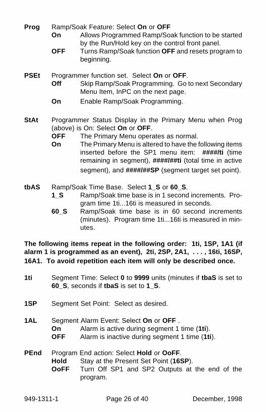
Prog Ramp/Soak Feature: Select On or OFFOn Allows Programmed Ramp/Soak function to be started
by the Run/Hold key on the control front panel.OFF Turns Ramp/Soak function OFF and resets program to
beginning.
PSEt Programmer function set. Select On or OFF.Off Skip Ramp/Soak Programming. Go to next Secondary
Menu Item, InPC on the next page.On Enable Ramp/Soak Programming.
StAt Programmer Status Display in the Primary Menu when Prog(above) is On: Select On or OFF.OFF The Primary Menu operates as normal.On The Primary Menu is altered to have the following items
inserted before the SP1 menu item: ####/ti (timeremaining in segment), ####/##ti (total time in activesegment), and ####/##SP (segment target set point).
tbAS Ramp/Soak Time Base. Select 1_S or 60_S.1_S Ramp/Soak time base is in 1 second increments. Pro-
gram time 1ti...16ti is measured in seconds.60_S Ramp/Soak time base is in 60 second increments
(minutes). Program time 1ti...16ti is measured in min-utes.
The following items repeat in the following order: 1ti, 1SP, 1A1 (ifalarm 1 is programmed as an event), 2ti, 2SP, 2A1, . . . , 16ti, 16SP,16A1. To avoid repetition each item will only be described once.
1ti Segment Time: Select 0 to 9999 units (minutes if tbaS is set to60_S, seconds if tbaS is set to 1_S.
1SP Segment Set Point: Select as desired.
1AL Segment Alarm Event: Select On or OFF .On Alarm is active during segment 1 time (1ti ).OFF Alarm is inactive during segment 1 time (1ti ).
PEnd Program End action: Select Hold or OoFF.Hold Stay at the Present Set Point (16SP).OoFF Turn Off SP1 and SP2 Outputs at the end of the
program.

December, 1998 Page 27 of 40 949-1311-1
LooP Repeat program starting at 1ti .SP1 Revert to SP1 value.
InPC Input Correction: Select ±500 °F, °C, or counts. This featureallows the input value to be changed to agree with an externalreference or to compensate for sensor error. Note: InPC is resetto zero when the input type is changed, or when decimal positionis changed.
FiLt Digital Filter: Select OFF, 1 to 99. In some cases the time constantof the sensor, or noise could cause the display to jump enoughto be unreadable. A setting of 2 is usually sufficient to provideenough filtering for most cases, (2 represents approximately a 1second time constant). When the 0.1 degree resolution is se-lected this should be increased to 4. If this value is set too high,controllability will suffer.
LPbr Loop Break Protection: Select OFF, 1 to 9999 seconds. If, duringoperation, the output is minimum (0%) or maximum (100%), andthe input moves less than 5°F (3°C) or 5 counts over the time setfor LPbr, the LOOP bAd message will appear. This condition canalso be routed to an Alarm Condition if alarms are present andturned On (see ALbr in the secure menu). The loop break error canbe reset by pressing the ENTER key when at the LPbr menu item.The INDEX & ENTER keys may also be used.
POL (Option 934, 936, Analog Retransmission Output) Process Out-put Low: Select -450°F, -260°C, or -1999 counts to any value lessthan POH.
POH (Option 934, 936, Analog Retransmission Output) Process Out-put High: Select from any value greater than POL to +9999°F,+5530°C, or 9999 counts.
POSr (Option 934, 936, Analog Retransmission Output) Process Out-put Source: Select InP or SPt.InP Process output follows the Process Variable (input).SPt Process Output follows the Set Variable (SP1).
rSPt (Option 924, 926, 928, Analog Remote Set Point) Remote SetPoint: Select On or OFF.OFF The control uses the value set for SP1.On The control uses the value set by the analog remote set
point signal as established by the Secure Menu itemsrSCL and rSCH. If the analog signal fails, the control will

949-1311-1 Page 28 of 40 December, 1998
display the error message CHEC/ LorE and revert to theSP1 local value.
LOrE (Option 992, Serial Communications) Local / Remote Status:Select LOC or rE.LOC The host computer is advised not to send remote
commands. Any write commands sent to the controlswill be rejected.
rE The host computer is allowed to send write commands.Ifthe control is not addressed within the time set in the nAt(No Activity Timer, see Secure Menu) the CHEC LorEerror message will be displayed.
Addr (Option 992, Serial Communications) Control Address: Set from1 to 3FF. This number (hexadecimal, base 16) must match theaddress number used by the host computer. Viewed only in thismenu. To change this parameter, see Addr in the Secure Menu.
SECURE MENUHold UP ARROW & ENTER for 5 Seconds. Press INDEX to advance tothe next menu item. Press UP ARROW or DOWN ARROW to change thevalue in the display. Press ENTER to retain the value.OUTPUTS ARE DISABLED (TURNED OFF) WHILE CONTROL IS INSECURE MENU.
SECr Security Code: See the Security Level Selection and the Pass-word Table in this manual, in order to enter the correct password.
InP Input Type: Select one of the following. Refer to the Input wiringsection for the proper wiring.
J-IC Type “J” ThermocoupleCA Type “K” ThermocoupleE- Type “E” Thermocouplet- Type “T” ThermocoupleL- Type “L” Thermocouplen- Type “N” Thermocoupler-13 Type “R” ThermocoupleS-10 Type “S” Thermocoupleb- Type “B” ThermocoupleC- Type “C” ThermocoupleP392 100 ohm Platinum (NIST 0.00392 Ω/Ω/°C)n120 120 ohm NickelP385 100 ohm Platinum (DIN 0.00385 Ω/Ω/°C)1P38 1000 ohm Platinum (DIN 0.00385 Ω/Ω/°C)Curr DC Current Input 0.0 to 20.0 or 4.0 to 20.0 mA.

December, 1998 Page 29 of 40 949-1311-1
VoLt DC Voltage Input 0.0 to 10.0 or 2.0 to 10.0 volts.diFF DC Voltage Input -10 to +10 mV.- - - - Reserved
OSUP Zero Suppression: Select On or OFF. Only with Current andVoltage input types.
OFF The input range will start at 0 (zero) Input.On The input range will start at 4.00 mA or 2.00 V.
Unit F , C or None .F °F descriptor is On and temperature inputs will be
displayed in actual degrees Fahrenheit.C °C descriptor is On and temperature inputs will be
displayed in actual degrees Celsius.nonE °F and °C descriptors will be Off. This is only available
with Current and Voltage Inputs.
dPt Decimal Point Positioning: Select 0, 0.0, 0.00, or 0.000 . Ontemperature type inputs this will only effect the Process Value,SP1, SP2, ALLo, ALHi, and InPC. For Current and Voltage Inputsall Menu Items related to the Input will be affected.0 No decimal Point is selected. This is available for all
Input Types.0.0 One decimal place is available for Type J, K, E, T, L,
RTD’s, Current and Voltage Inputs.0.00 Two decimal places is only available for Current and
Voltage Inputs.0.000 Three decimal places is only available for Current and
Voltage inputs.
InPt Input Fault Timer: Select OFF, 0.1 to 540.0 minutes. Wheneveran Input is out of range (UFL or OFL displayed), shorted, or openthe timer will start. When the time has elapsed, the controller willrevert to the output condition selected by InPb below. If OFF isselected, the Input Fault Timer will not be recognized (time =infinite).
InPb Input Fail Aciton: Select FAIL, AVE, or PrE. When the Input is outof range (UFL or OFL displayed) and the Input timer (InPt ) timehas elapsed, the controller will revert to the selected condition.FAIL Outputs are disabled (go to 0% output).AVE The outputs will hold at the last known average percent-
age of output.PrE The outputs will maintain a preprogrammed percentage

949-1311-1 Page 30 of 40 December, 1998
of output as specified in PrE1 and PrE2.PrE1 Preset output for Set Point 1. Select 0 to 100%.PrE2 Preset output for Set Point 2. Select 0 to 100%.
APCt Manual and PctO display adjustment. Select rEAL or AdJ .rEAL Manual display will display output 0 to 100% relative to
actual range of the output.AdJ Manual display will display output 0 to 100% relative to
the S#OL and S#OH settings.
SEnC Sensor Rate of Change: Select OFF, 1 to 4000 °F, °C, or countsper 1 second period. This value is usually set to be slightly greaterthan the fastest process response expected during a 1 secondperiod, but measured for at least 2 seconds. If the process is fasterthan this setting, the SEnC bAd error message will appear. Theoutputs will then be turned off. This function can be used to detecta runaway condition, or speed up detection of an open thermo-couple. Use the INDEX & ENTER keys to reset.
SCAL Scale Low: Select 100 to 9999 counts below SCAH. The totalspan between SCAL and SCAH must be within 11998 counts.Maximum setting range is -1999 to +9999 counts. For Current andVoltage inputs, this will set the low range end. Viewable only forThermocouple and RTD ranges.
SCAH Scale High: Select 100 to 9999 counts above SCAL . The totalspan between SCAL and SCAH must be within 11998 counts.Maximum setting range is -1999 to +9999 counts. For Current andVoltage inputs, this will set the high range end. Viewable only forThermocouple and RTD ranges.
SPL Set Point Low: Select from the lowest input range value to SPHvalue. This will set the minimum SP1 or SP2 value that can beentered. The value for SP1 or SP2 will not stop moving when thisvalue is reached. If equipped with option 924 or 926, if SPL is setabove rSCL then control will revert to SP1 if remote value goesbelow SPL.
SPH Set Point High: Select from the highest input range value to SPLvalue. This will set the maximum SP1 or SP2 value that can beentered. The value for SP1 or SP2 will not stop moving when thisvalue is reached.. If equipped with option 924 or 926, if SPH is setbelow rSCH then control will revert to SP1 if remote value goesabove SPH.
December, 1998 Page 31 of 40 949-1311-1
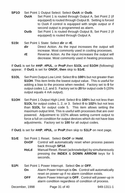
SP1O Set Point 1 Output Select: Select OutA or Outb .OutA Set Point 1 is routed through Output A, Set Point 2 (if
equipped) is routed through Output B. Setting is forcedto OutA if control is equipped with single output or ifsecond output is programmed as alarm.
Outb Set Point 1 is routed through Output B, Set Point 2 (ifequipped) is routed through Output A.
S1St Set Point 1 State: Select dir or rE.dir Direct Action. As the input increases the output will
increase. Most commonly used in cooling processes.rE Reverse Action. As the input increases the output will
decrease. Most commonly used in heating processes.
If Out1 is set for ##tP, #PUL, or ProP ,then S1OL and S1OH (following)appear. If Out1 is set for ONOF, then skip to S1rE.
S1OL Set Point Output Low Limit: Select 0 to 100% but not greater thanS1OH. This item limits the lowest output value. This is useful foradding a bias to the process when needed. Factory set to 0 foroutput codes 1,2, and 3. Factory set to 20 for output code 5 (20%output equals 4 mA output).
S1OH Set Point 1 Output High Limit: Select 0 to 100% but not less thanS1OL for output codes 1, 2, or 3. Select 0 to 102% but not lessthan S1OL for output code 5. This item allows setting themaximum output limit. This is useful with processes that are overpowered. Adjustment to 102% allows setting current output toforce a full on condition for output devices which do not have biasadjustments. Factory set to 100 for all output codes.
If Out1 is set for ##tP, #PUL, or ProP ,then skip to S1LP on next page.
S1rE Set Point 1 Reset. Select OnOF or Hold .OnOF Control will automatically reset when process passes
back through SP1d.HoLd Manual Reset. Reset (acknowledge) by simultaneously
pressing the INDEX & DOWN ARROW keys for 5seconds.
S1Pi Set Point 1 Power Interrupt. Select On or OFF.On Alarm Power Interrupt is On. Control will automatically
reset on power-up if no alarm condition exists.OFF Alarm Power Interrupt is OFF. Control will power-up in
alarm condition regardless of condition of process.

949-1311-1 Page 32 of 40 December, 1998
S1iH Set Point 1 Inhibit: Select On or OFF.On Alarm Inhibit is On. Alarm action is suspended until the
process value first enters a non-alarm condition.OFF Alarm Inhibit is OFF.
S1LP Set Point Lamp: Select O on or OoFF.O on Lamp ON when Output is ON.OoFF Lamp OFF when Output is ON.
If your control is not equipped with a second output or if the secondoutput is programmed as an alarm, then proceed to the alarm section(next page).
S2t Set Point 2 type: Select Abs or dE.AbS Absolute SP2. SP2 is independent of SP1, and may be
set anywhere between the limits of SPL and SPH.dE Deviation SP2. SP2 is set as a deviation from SP1, and
allows SP2 to retain its relationship with SP1 when SP1is changed (tracking SP2).
S2St Set Point 2 State: Select dir or rE.dir Direct Action. As the input increases the output will
increase. Most commonly used in cooling processes.rE Reverse Action. As the input increases the output will
decrease. Most commonly used in heating processes.
If Out2 is set for ##tP, #PUL, or ProP ,then S2OL and S2OH (following)appear. If Out2 is set for ONOF, then skip to S2rE.
S2OL Set Point Output Low Limit: Select 0 to 100% but not greater thanS2OH. This item limits the lowest output value. This is useful foradding a bias to the process when needed. Factory set to 0 foroutput codes 1,2, and 3. Factory set to 20 for output code 5 (20%output equals 4 mA output).
S2OH Set Point 1 Output High Limit: Select 0 to 100% but not less thanS2OL for output codes 1, 2, or 3. Select 0 to 102% but not lessthan S2OL for output code 5. This item allows setting themaximum output limit. This is useful with processes that are overpowered. Adjustment to 102% allows setting current output toforce a full on condition for output devices which do not have biasadjustments. Factory set to 100 for all output codes.

December, 1998 Page 33 of 40 949-1311-1
S2rE Set Point 2 Reset. Select OnOF or Hold .OnOF Control will automatically reset when process passes
back through SP2d.HoLd Manual Reset. Reset (acknowledge) by simultaneously
pressing the INDEX & DOWN ARROW keys for 5seconds.
S2Pi Set Point 2 Power Interrupt. Select On or OFF.On Alarm Power Interrupt is On. Control will automatically
reset on power-up if no alarm condition exists.OFF Alarm Power Interrupt is OFF. Control will power-up in
alarm condition regardless of condition of process.
S2iH Set Point 2 Inhibit: Select On or OFF.On Alarm Inhibit is On. Alarm action is suspended until the
process value first enters a non-alarm condition.OFF Alarm Inhibit is OFF.
S2LP Set Point 2 Lamp: Select O on or OoFF.O on Lamp ON when Output is ON.OoFF Lamp OFF when Output is ON.
The following menu item applies only to the alarm when programmed.
AL Alarm function: Select OFF, Lo, Hi , HiLo, or Evnt.OFF Alarm is disabled. No Alarm menu items appear in the
Secondary or Secure menus.Lo Low Alarm Only. ALLo appears in the Secondary
Menu.Hi High Alarm Only. ALHi appears in the Secondary
Menu.HiLo High and Low Alarms. Both ALLo and ALHi appear in
the Secondary Menu, and share the same Alarm Relayoutput.
Evnt Alarm is controlled by the Ramp/Soak program func-tion. See pages 11-13 (#AL ) for further information.
If AL is set to OFF and the control is not equipped with options, the SecureMenu ends. If AL is set to OFF or the second output is programmed ascontrol, and the control is equipped with options, proceed to SPSA, Addr ,or rSCL on the next page.
If AL is set to Evnt , go to ALSt on the next page.
949-1311-1 Page 34 of 40 December, 1998
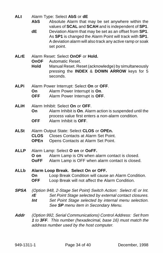
ALt Alarm Type: Select AbS or dEAbS Absolute Alarm that may be set anywhere within the
values of SCAL and SCAH and is independent of SP1.dE Deviation Alarm that may be set as an offset from SP1.
As SP1 is changed the Alarm Point will track with SP1.A deviation alarm will also track any active ramp or soakset point.
ALrE Alarm Reset: Select OnOF or Hold.OnOF Automatic Reset.Hold Manual Reset. Reset (acknowledge) by simultaneously
pressing the INDEX & DOWN ARROW keys for 5seconds.
ALPi Alarm Power Interrupt: Select On or OFF.On Alarm Power Interrupt is On.OFF Alarm Power Interrupt is OFF.
ALiH Alarm Inhibit: Select On or OFF.On Alarm Inhibit is On. Alarm action is suspended until the
process value first enters a non-alarm condition.OFF Alarm Inhibit is OFF.
ALSt Alarm Output State: Select CLOS or OPEn.CLOS Closes Contacts at Alarm Set Point.OPEn Opens Contacts at Alarm Set Point.
ALLP Alarm Lamp: Select O on or OoFF.O on Alarm Lamp is ON when alarm contact is closed.OoFF Alarm Lamp is OFF when alarm contact is closed.
ALLb Alarm Loop Break. Select On or OFF.On Loop Break Condition will cause an Alarm Condition.OFF Loop Break will not affect the Alarm Condition.
SPSA (Option 948, 2-Stage Set Point) Switch Action: Select rE or Int.rE Set Point Stage selected by external contact closures.Int Set Point Stage selected by internal menu selection.
See SP menu item in Secondary Menu.
Addr (Option 992, Serial Communications) Control Address: Set from1 to 3FF. This number (hexadecimal, base 16) must match theaddress number used by the host computer.

December, 1998 Page 35 of 40 949-1311-1
bAUd (Option 992, Serial Communications) Communication Baud Rate:Select 300, 1200, 2400, 4800, 9600, or 19200. This number mustmatch the baud rate used by the host computer.
nAt (Option 992, Serial Communications) No Activity Timer: Set fromOFF or 1 to 99 minutes.1 - 99 Maximum time between host computer accesses. If
timer counts to 0, CHEC/LorE will be displayed.OFF No Activity Timer function is disabled.
rSCL (Option 924, 926, 928, Analog Remote Set Point) Remote ScaleLow: Select 100 to 9999 counts below rSCH. The total spanbetween rSCL and rSCH must be within 11998 counts. Maximumsetting range is -1999 to +9999 counts.
rSCH (Option 924, 926, 928, Analog Remote Set Point) Remote ScaleHigh: Select 100 to 9999 counts above rSCL . The total spanbetween rSCL and rSCH must be within 11998 counts. Maximumsetting range is -1999 to +9999 counts.
SPECIFICATIONS
Selectable Inputs: Thermocouple, RTD, DC Voltage, or DC Currentselectable.
Input Impedance:Thermocouple = 3 megohms minimum. RTD current = 200 µA.Current = 10 ohms. Voltage = 5000 ohms.
Sensor Break Protection: De-energizes control output to protect systemafter customer set time. (See InPt in Secondary Menu.)
Set Point Range: Selectable (See Range Chart Page 39).Display: Two 4 digit, 7 segment 6.35 mm (0.25") high LEDs.Control Action: Reverse (usually heating), Direct (usually cooling) select-
able.Proportional Band: 1 to 9999 °F, °C, or counts.Reset Time (Integral): Off or 0.1 to 99.9 minutes.Rate Time (Derivative): Off or 0.01 to 99.99 minutes.Cycle Rate: 1 to 80 seconds.On - Off Differential: Adjustable 1° F, 1° C, or 1 count to full scale in 1° F,
1° C, or 1 count steps.Alarm On - Off Differential: 1° F, 1° C, or 1 count.Fuzzy Percent: 0 to 100%.

949-1311-1 Page 36 of 40 December, 1998
Fuzzy Rate: Off or 0.01 to 99.99 minutes.Fuzzy Band: Off or 1 to 4000 °F, °C, or counts.Accuracy: ±0.25% of span, ±1 least significant digit.Resolution: 1 degree or 0.1 degree, selectable.Line Voltage Stability: ±0.05% over the supply voltage range.Temperature Stability: 4µV/°C (2.3 µV/°F) typical, 8 µV/°C (4.5 µV°F)
maximum (100 ppm / °C typical, 200 ppm / °C maximum).Common Mode Rejection: 140 db minimum at 60 Hz.Normal Mode Rejection: 65 db typical, 60 db at 60 Hz.Isolation:
Relay and SSR outputs: 1500 Vac to all other inputs and outputs.SP1 Current output: Non-isolated, share common groung with input.SP1 and SP2 Switched Voltage outputs: Non-isolated, sharescommon ground with input.Process Output (934, 936): 500 VAC to all other inputs and outputs.
Supply Voltage: 100 to 240 Vac, nominal., +10 -15%, 50 to 400 Hz. singlephase; 132 to 240 Vdc, nominal., +10 -20%.
Supply Voltage (Option 9502): 12 to 24 Vdc, Vac 40-400 Hz, ±20%.Power Consumption: 5VA maximum.Operating Temperature: -10 to +55 °C (+14 to 131 °F).Storage Temperature: -40 to +80 °C (-40 to 176 °F).Humidity Conditions: 0 to 90% up to 40 °C non-condensing, 10 to 50% at
55 °C non-condensing.Memory Backup: Nonvolatile memory. No batteries required.Control Output Ratings:
AC SSR (Output A, Output B): 0.75 A @ 240 Vac at 25 °C (77°F).Derates to 0.5 A @ 55° C (130°F).DC SSR (Output A, Output B): 1.25 A @ 32VDC at 25° C (77°F),
derates to 1.0 A at 55° C (130°F).Relay (Output A, Output B): SPST, 3 A @ 240 Vac resistive; 1.5A
@240 Vac inductive; 1/10 HP @ 120 Vac.Current (non-isolated, Output A only): 0 to 20 mA across 600ohms maximum.Switched Voltage (non-isolated, Output A, Output B): 5 Vdc @20 mA.
Panel Cutout: 45.0 mm x 22.2 mm (1.772" x 0.874").Depth Behind Mounting Surface: 111.6 mm (4.395").Weight: 114 g (4 oz).Agency Approvals: CE.Front Panel Rating: Type 4, IP66.
December, 1998 Page 37 of 40 949-1311-1
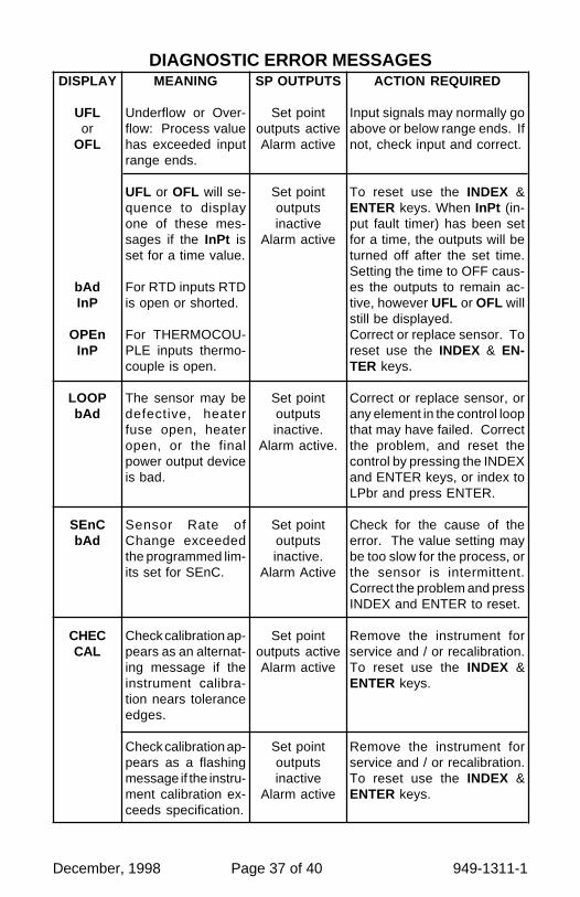
SP OUTPUTS
Set pointoutputs activeAlarm active
Set pointoutputsinactive
Alarm active
Set pointoutputsinactive.
Alarm active.
Set pointoutputsinactive.
Alarm Active
Set pointoutputs activeAlarm active
Set pointoutputsinactive
Alarm active
ACTION REQUIRED
Input signals may normally goabove or below range ends. Ifnot, check input and correct.
To reset use the INDEX &ENTER keys. When InPt (in-put fault timer) has been setfor a time, the outputs will beturned off after the set time.Setting the time to OFF caus-es the outputs to remain ac-tive, however UFL or OFL willstill be displayed.Correct or replace sensor. Toreset use the INDEX & EN-TER keys.
Correct or replace sensor, orany element in the control loopthat may have failed. Correctthe problem, and reset thecontrol by pressing the INDEXand ENTER keys, or index toLPbr and press ENTER.
Check for the cause of theerror. The value setting maybe too slow for the process, orthe sensor is intermittent.Correct the problem and pressINDEX and ENTER to reset.
Remove the instrument forservice and / or recalibration.To reset use the INDEX &ENTER keys.
Remove the instrument forservice and / or recalibration.To reset use the INDEX &ENTER keys.
MEANING
Underflow or Over-flow: Process valuehas exceeded inputrange ends.
UFL or OFL will se-quence to displayone of these mes-sages if the InPt isset for a time value.
For RTD inputs RTDis open or shorted.
For THERMOCOU-PLE inputs thermo-couple is open.
The sensor may bedefective, heaterfuse open, heateropen, or the finalpower output deviceis bad.
Sensor Rate ofChange exceededthe programmed lim-its set for SEnC.
Check calibration ap-pears as an alternat-ing message if theinstrument calibra-tion nears toleranceedges.
Check calibration ap-pears as a flashingmessage if the instru-ment calibration ex-ceeds specification.
DIAGNOSTIC ERROR MESSAGESDISPLAY
UFLor
OFL
bAdInP
OPEnInP
LOOPbAd
SEnCbAd
CHECCAL

949-1311-1 Page 38 of 40 December, 1998
DISPLAY
Nodisplaylighted
FAILtESt
CHECSP1,
CHECSP2,
CHEC1SP, ...,CHEC16SP,
CHECSPLor
CHECSPH
CHECrSpt
CHECLorE
ArEA(Alter-nates
with PVwhennear)
MEANING
Display is blank. In-strument is not get-ting power, or thesupply voltage is toolow.
Fail test appearsupon power up if theinternal diagnosticsdetect a failure. Thismessage may oc-cur during operationif a failure is detect-ed. Displays flash.
This message willappear upon powerup if SP1, SP2,#SP1, or ##SP isset outside of theSPL or SPH values.
This message ap-pears at power up ifSPL or SPH valuesare programmedoutside the inputrange ends.
This message ap-pears if the analogremote set point sig-nal is out of range.
This message ap-pears if the SerialCommunicat ionshas timed out.
This message ap-pears if the ambiienttemperature of thecontrol is near or outof range or RJC sen-sor is broken.
SP OUTPUTS
Set pointoutputs inactiveAlarm inactive
Set pointoutputs inactiveAlarm inactive
Set pointoutputs inactive
Alarm active
Set pointoutputs inactiveAlarm inactive
Set pointoutputs activeAlarm inactive
Set pointoutputs activeAlarm inactive
Set pointoutputs activeAlarms active
ACTION REQUIRED
Check that the power supply ison, or that the external fusesare good.
The display alternate betweenFAIL tESt and one of the fol-lowing messages: FACt dFLt :Memory may be corrupted.Press the ENTER key and theDOWN ARROW key to startthe factory default procedure.Recheck controller program-ming. rEt FACt : Unrecover-able error, return to factory forservice.
Correct the SP1, etc. or adjustthe SPL or SPH values byprogramming new values.
Correct the SPL or SPH val-ues by programming new val-ues.
The control will revert to SP1.Correction of the analog sig-nal allows the control to returnto the remote
Restore the communicationsline and switch the LorE toLOC.
Correct the ambient tempera-ture conditions. Ventilate thearea of the cabinet or checkfor clogged filters. If RJC bro-ken, return to factory for ser-vice.
DIAGNOSTIC ERROR MESSAGES

December, 1998 Page 39 of 40 949-1311-1
Input Ranges (Field Selectable)Thermocouple Types
InputType
Range1°F1°C
Type J or L*
-100 to +1600-73 to +871
Type K*
-200 to +2500-129 to +1371
Type T*
-350 to +750-212 to +398
Type E*
-100 to +1800-73 to +982
InputType
Range1°F1°C
Type R
0 to 3200-17 to +1760
Type S
0 to 3200-17 to +1760
Type B
+75 to 3308+24 to 1820
Type C
0 to 4208-17 to 2320
InputType
Range1°F1°C
Type N*
-100 to +2372-73 to +1300
RTD TypesInputType
Range1°F1°C
100 OhmPlatinum
0.00385 DINCurve*
-328 to +1607-200 to +875
100 OhmPlatinum
0.00392 NistCurve*
-328 to +1607-200 to +875
120 OhmNickel
0.00628 USInd. Curve*
-112 to +608-80 to +320
1000 OhmPlatinum
0.00385 NistCurve*
-328 to +1607-200 to +875
Process Input Types
* These Input Types can be set for 0.1° display.If temperature goes above 999.9° or less than-199.9° the display will return to whole degreeresolution.
The 0 to 20 mAdc, 4 to 20 mAdc, 0 to 10 Vdc, 2 to 10 Vdc, and -10 to +10mVdc inputs are fully scalable from a minimum of 100 counts span placedanywhere within the within the range of -1999 to +9999. Decimal pointposition is adjustable from the zero place (9999), tenths (999.9), hun-dredths (99.99), or thousandths (9.999).

949-1311-1 Page 40 of 40 December, 1998
DIMENSIONS
ALL DIMENSIONS IN MILLIMETERS (INCHES)
PANEL CUT OUT: 45 +0.6 X 22.2 +0.3 (1.772 +0.02 X 0.874 +0.012)
22.1(0.870)
111.6(4.395)
11(0.433)
30.1(1.184)
52.8(2.080)
44.86(1.786)
6.35 (0.25)Maximum Panel Thickness
Dwyer Instruments, IncorporatedPO Box 338 Michigan City, IN 46361-0338
(800) 828-4588 (219) 879-8000 FAX (219) 872-9057
www.love-controls.com
m m
m
LOVE CONTROLS DIVISION
®


