310
WARNING! To properly use this medical device, read and comply with these Instructions for Use. Anesthesia Workstation Software 4.5n Instructions for Use Apollo
WARNING!To properly use this medical device, read and comply with these Instructions for Use.
Anesthesia WorkstationSoftware 4.5n
Instructions for Use
Apollo

This page intentionally left blank.
Contents
Par
t Num
ber:
905
3586
, 3rd
edi
tion
Introduction . . . . . . . . . . . . . . . . . . . . . . . . . . . . . . . . . . . . . . . . . . . . . . . . . . . . . . . . . . . . . . . 7Contents . . . . . . . . . . . . . . . . . . . . . . . . . . . . . . . . . . . . . . . . . . . . . . . . . . . . . . . . . . . . . . . . . . . . . . . . . . . . . . . . . 7Working with these instructions for use. . . . . . . . . . . . . . . . . . . . . . . . . . . . . . . . . . . . . . . . . . . . . . . . . . . . . . . . . . 9Use of terms . . . . . . . . . . . . . . . . . . . . . . . . . . . . . . . . . . . . . . . . . . . . . . . . . . . . . . . . . . . . . . . . . . . . . . . . . . . . . 10Screen layouts and illustrations of the device . . . . . . . . . . . . . . . . . . . . . . . . . . . . . . . . . . . . . . . . . . . . . . . . . . . . 10Trademarks . . . . . . . . . . . . . . . . . . . . . . . . . . . . . . . . . . . . . . . . . . . . . . . . . . . . . . . . . . . . . . . . . . . . . . . . . . . . . . 10Safety information definitions . . . . . . . . . . . . . . . . . . . . . . . . . . . . . . . . . . . . . . . . . . . . . . . . . . . . . . . . . . . . . . . . 10Definition of target groups . . . . . . . . . . . . . . . . . . . . . . . . . . . . . . . . . . . . . . . . . . . . . . . . . . . . . . . . . . . . . . . . . . . 10Abbreviations and symbols . . . . . . . . . . . . . . . . . . . . . . . . . . . . . . . . . . . . . . . . . . . . . . . . . . . . . . . . . . . . . . . . . . 11General safety information . . . . . . . . . . . . . . . . . . . . . . . . . . . . . . . . . . . . . . . . . . . . . . . . . . . . . . . . . . . . . . . . . . 11Product-specific safety information . . . . . . . . . . . . . . . . . . . . . . . . . . . . . . . . . . . . . . . . . . . . . . . . . . . . . . . . . . . . 14Indications and contraindications . . . . . . . . . . . . . . . . . . . . . . . . . . . . . . . . . . . . . . . . . . . . . . . . . . . . . . . . . . . . . 16Intended Use. . . . . . . . . . . . . . . . . . . . . . . . . . . . . . . . . . . . . . . . . . . . . . . . . . . . . . . . . . . . . . . . . . . . . . . . . . . . . 16Environment of use . . . . . . . . . . . . . . . . . . . . . . . . . . . . . . . . . . . . . . . . . . . . . . . . . . . . . . . . . . . . . . . . . . . . . . . . 18Additional functions . . . . . . . . . . . . . . . . . . . . . . . . . . . . . . . . . . . . . . . . . . . . . . . . . . . . . . . . . . . . . . . . . . . . . . . . 19Accessory weight limits . . . . . . . . . . . . . . . . . . . . . . . . . . . . . . . . . . . . . . . . . . . . . . . . . . . . . . . . . . . . . . . . . . . . . 20Symbols . . . . . . . . . . . . . . . . . . . . . . . . . . . . . . . . . . . . . . . . . . . . . . . . . . . . . . . . . . . . . . . . . . . . . . . . . . . . . . . . 21Abbreviations . . . . . . . . . . . . . . . . . . . . . . . . . . . . . . . . . . . . . . . . . . . . . . . . . . . . . . . . . . . . . . . . . . . . . . . . . . . . 23
System Components. . . . . . . . . . . . . . . . . . . . . . . . . . . . . . . . . . . . . . . . . . . . . . . . . . . . . . . 27Contents . . . . . . . . . . . . . . . . . . . . . . . . . . . . . . . . . . . . . . . . . . . . . . . . . . . . . . . . . . . . . . . . . . . . . . . . . . . . . . . . 27Overview . . . . . . . . . . . . . . . . . . . . . . . . . . . . . . . . . . . . . . . . . . . . . . . . . . . . . . . . . . . . . . . . . . . . . . . . . . . . . . . . 29Machine Front view . . . . . . . . . . . . . . . . . . . . . . . . . . . . . . . . . . . . . . . . . . . . . . . . . . . . . . . . . . . . . . . . . . . . . . . . 29Machine Rear view . . . . . . . . . . . . . . . . . . . . . . . . . . . . . . . . . . . . . . . . . . . . . . . . . . . . . . . . . . . . . . . . . . . . . . . . 30Gas supply block. . . . . . . . . . . . . . . . . . . . . . . . . . . . . . . . . . . . . . . . . . . . . . . . . . . . . . . . . . . . . . . . . . . . . . . . . . 31Interface panel . . . . . . . . . . . . . . . . . . . . . . . . . . . . . . . . . . . . . . . . . . . . . . . . . . . . . . . . . . . . . . . . . . . . . . . . . . . 32Vaporizers (Optional) . . . . . . . . . . . . . . . . . . . . . . . . . . . . . . . . . . . . . . . . . . . . . . . . . . . . . . . . . . . . . . . . . . . . . . 33Vaporizer exclusion systems. . . . . . . . . . . . . . . . . . . . . . . . . . . . . . . . . . . . . . . . . . . . . . . . . . . . . . . . . . . . . . . . . 34APL valve . . . . . . . . . . . . . . . . . . . . . . . . . . . . . . . . . . . . . . . . . . . . . . . . . . . . . . . . . . . . . . . . . . . . . . . . . . . . . . . 36O2 flush. . . . . . . . . . . . . . . . . . . . . . . . . . . . . . . . . . . . . . . . . . . . . . . . . . . . . . . . . . . . . . . . . . . . . . . . . . . . . . . . . 37Auxiliary oxygen flow meter . . . . . . . . . . . . . . . . . . . . . . . . . . . . . . . . . . . . . . . . . . . . . . . . . . . . . . . . . . . . . . . . . 37Writing table . . . . . . . . . . . . . . . . . . . . . . . . . . . . . . . . . . . . . . . . . . . . . . . . . . . . . . . . . . . . . . . . . . . . . . . . . . . . . 39Gas flow diagram . . . . . . . . . . . . . . . . . . . . . . . . . . . . . . . . . . . . . . . . . . . . . . . . . . . . . . . . . . . . . . . . . . . . . . . . . 39
User Interface. . . . . . . . . . . . . . . . . . . . . . . . . . . . . . . . . . . . . . . . . . . . . . . . . . . . . . . . . . . . . 41Contents . . . . . . . . . . . . . . . . . . . . . . . . . . . . . . . . . . . . . . . . . . . . . . . . . . . . . . . . . . . . . . . . . . . . . . . . . . . . . . . . 41Overview . . . . . . . . . . . . . . . . . . . . . . . . . . . . . . . . . . . . . . . . . . . . . . . . . . . . . . . . . . . . . . . . . . . . . . . . . . . . . . . . 43User controls . . . . . . . . . . . . . . . . . . . . . . . . . . . . . . . . . . . . . . . . . . . . . . . . . . . . . . . . . . . . . . . . . . . . . . . . . . . . . 45LED indicators. . . . . . . . . . . . . . . . . . . . . . . . . . . . . . . . . . . . . . . . . . . . . . . . . . . . . . . . . . . . . . . . . . . . . . . . . . . . 49Screen colors . . . . . . . . . . . . . . . . . . . . . . . . . . . . . . . . . . . . . . . . . . . . . . . . . . . . . . . . . . . . . . . . . . . . . . . . . . . . 49Menu structure overview . . . . . . . . . . . . . . . . . . . . . . . . . . . . . . . . . . . . . . . . . . . . . . . . . . . . . . . . . . . . . . . . . . . . 51
System Setup. . . . . . . . . . . . . . . . . . . . . . . . . . . . . . . . . . . . . . . . . . . . . . . . . . . . . . . . . . . . . 57Contents . . . . . . . . . . . . . . . . . . . . . . . . . . . . . . . . . . . . . . . . . . . . . . . . . . . . . . . . . . . . . . . . . . . . . . . . . . . . . . . . 57Overview . . . . . . . . . . . . . . . . . . . . . . . . . . . . . . . . . . . . . . . . . . . . . . . . . . . . . . . . . . . . . . . . . . . . . . . . . . . . . . . . 59Preparation before first use. . . . . . . . . . . . . . . . . . . . . . . . . . . . . . . . . . . . . . . . . . . . . . . . . . . . . . . . . . . . . . . . . . 59Charging the battery for emergency operation . . . . . . . . . . . . . . . . . . . . . . . . . . . . . . . . . . . . . . . . . . . . . . . . . . . 59Installing the breathing system and flow sensors . . . . . . . . . . . . . . . . . . . . . . . . . . . . . . . . . . . . . . . . . . . . . . . . . 61Filling and installing the absorber . . . . . . . . . . . . . . . . . . . . . . . . . . . . . . . . . . . . . . . . . . . . . . . . . . . . . . . . . . . . . 63Connecting the gas supply . . . . . . . . . . . . . . . . . . . . . . . . . . . . . . . . . . . . . . . . . . . . . . . . . . . . . . . . . . . . . . . . . . 65Connecting the scavenger system . . . . . . . . . . . . . . . . . . . . . . . . . . . . . . . . . . . . . . . . . . . . . . . . . . . . . . . . . . . . 71Connecting the endotracheal aspiration system (Optional) . . . . . . . . . . . . . . . . . . . . . . . . . . . . . . . . . . . . . . . . . 74Installing vaporizers . . . . . . . . . . . . . . . . . . . . . . . . . . . . . . . . . . . . . . . . . . . . . . . . . . . . . . . . . . . . . . . . . . . . . . . 74
Instructions for Use Apollo SW 4.5n 3
Contents
Pa
rt Num
ber: 905358
6, 3rd edition
Installing the flexible arm for the breathing bag . . . . . . . . . . . . . . . . . . . . . . . . . . . . . . . . . . . . . . . . . . . . . . . . . . . 75Connecting the patient system. . . . . . . . . . . . . . . . . . . . . . . . . . . . . . . . . . . . . . . . . . . . . . . . . . . . . . . . . . . . . . . . 76Connecting AC power . . . . . . . . . . . . . . . . . . . . . . . . . . . . . . . . . . . . . . . . . . . . . . . . . . . . . . . . . . . . . . . . . . . . . . 84Information about transport within the clinic. . . . . . . . . . . . . . . . . . . . . . . . . . . . . . . . . . . . . . . . . . . . . . . . . . . . . . 86
Pre-use Checkout. . . . . . . . . . . . . . . . . . . . . . . . . . . . . . . . . . . . . . . . . . . . . . . . . . . . . . . . . . 89Contents. . . . . . . . . . . . . . . . . . . . . . . . . . . . . . . . . . . . . . . . . . . . . . . . . . . . . . . . . . . . . . . . . . . . . . . . . . . . . . . . . 89Overview . . . . . . . . . . . . . . . . . . . . . . . . . . . . . . . . . . . . . . . . . . . . . . . . . . . . . . . . . . . . . . . . . . . . . . . . . . . . . . . . 91Checking the Workstation according to the Check List . . . . . . . . . . . . . . . . . . . . . . . . . . . . . . . . . . . . . . . . . . . . . 91Self test . . . . . . . . . . . . . . . . . . . . . . . . . . . . . . . . . . . . . . . . . . . . . . . . . . . . . . . . . . . . . . . . . . . . . . . . . . . . . . . . 100System compliance . . . . . . . . . . . . . . . . . . . . . . . . . . . . . . . . . . . . . . . . . . . . . . . . . . . . . . . . . . . . . . . . . . . . . . . 103Leak tests. . . . . . . . . . . . . . . . . . . . . . . . . . . . . . . . . . . . . . . . . . . . . . . . . . . . . . . . . . . . . . . . . . . . . . . . . . . . . . . 103Emergency start . . . . . . . . . . . . . . . . . . . . . . . . . . . . . . . . . . . . . . . . . . . . . . . . . . . . . . . . . . . . . . . . . . . . . . . . . . 107
Operation Summary . . . . . . . . . . . . . . . . . . . . . . . . . . . . . . . . . . . . . . . . . . . . . . . . . . . . . . . 109Contents. . . . . . . . . . . . . . . . . . . . . . . . . . . . . . . . . . . . . . . . . . . . . . . . . . . . . . . . . . . . . . . . . . . . . . . . . . . . . . . . 109Overview . . . . . . . . . . . . . . . . . . . . . . . . . . . . . . . . . . . . . . . . . . . . . . . . . . . . . . . . . . . . . . . . . . . . . . . . . . . . . . . 111Safety Information . . . . . . . . . . . . . . . . . . . . . . . . . . . . . . . . . . . . . . . . . . . . . . . . . . . . . . . . . . . . . . . . . . . . . . . . 111Typical operation . . . . . . . . . . . . . . . . . . . . . . . . . . . . . . . . . . . . . . . . . . . . . . . . . . . . . . . . . . . . . . . . . . . . . . . . . 111Changing patients . . . . . . . . . . . . . . . . . . . . . . . . . . . . . . . . . . . . . . . . . . . . . . . . . . . . . . . . . . . . . . . . . . . . . . . . 115Changing soda lime . . . . . . . . . . . . . . . . . . . . . . . . . . . . . . . . . . . . . . . . . . . . . . . . . . . . . . . . . . . . . . . . . . . . . . . 116Leak test. . . . . . . . . . . . . . . . . . . . . . . . . . . . . . . . . . . . . . . . . . . . . . . . . . . . . . . . . . . . . . . . . . . . . . . . . . . . . . . . 118Activating the CO2 bypass function (Optional) . . . . . . . . . . . . . . . . . . . . . . . . . . . . . . . . . . . . . . . . . . . . . . . . . . 119End of operation. . . . . . . . . . . . . . . . . . . . . . . . . . . . . . . . . . . . . . . . . . . . . . . . . . . . . . . . . . . . . . . . . . . . . . . . . . 120When Apollo is not in use. . . . . . . . . . . . . . . . . . . . . . . . . . . . . . . . . . . . . . . . . . . . . . . . . . . . . . . . . . . . . . . . . . . 122
Ventilation . . . . . . . . . . . . . . . . . . . . . . . . . . . . . . . . . . . . . . . . . . . . . . . . . . . . . . . . . . . . . . . 123Contents. . . . . . . . . . . . . . . . . . . . . . . . . . . . . . . . . . . . . . . . . . . . . . . . . . . . . . . . . . . . . . . . . . . . . . . . . . . . . . . . 123Overview . . . . . . . . . . . . . . . . . . . . . . . . . . . . . . . . . . . . . . . . . . . . . . . . . . . . . . . . . . . . . . . . . . . . . . . . . . . . . . . 125Manual/Spontaneous ventilation . . . . . . . . . . . . . . . . . . . . . . . . . . . . . . . . . . . . . . . . . . . . . . . . . . . . . . . . . . . . . 126Volume-Controlled Ventilation . . . . . . . . . . . . . . . . . . . . . . . . . . . . . . . . . . . . . . . . . . . . . . . . . . . . . . . . . . . . . . . 129Volume Mode AutoFlow - Volume AF (Optional) . . . . . . . . . . . . . . . . . . . . . . . . . . . . . . . . . . . . . . . . . . . . . . . . . 133Pressure-Controlled Ventilation . . . . . . . . . . . . . . . . . . . . . . . . . . . . . . . . . . . . . . . . . . . . . . . . . . . . . . . . . . . . . . 138Pressure Support Ventilation (Optional). . . . . . . . . . . . . . . . . . . . . . . . . . . . . . . . . . . . . . . . . . . . . . . . . . . . . . . . 142Continuous Positive Airway Pressure CPAP - in Pressure Support Mode (Optional) . . . . . . . . . . . . . . . . . . . . . 145Changing between ventilation modes . . . . . . . . . . . . . . . . . . . . . . . . . . . . . . . . . . . . . . . . . . . . . . . . . . . . . . . . . 146Automatic parameter changes . . . . . . . . . . . . . . . . . . . . . . . . . . . . . . . . . . . . . . . . . . . . . . . . . . . . . . . . . . . . . . . 147Auxiliary common gas outlet (Aux CGO) ventilation (Optional) . . . . . . . . . . . . . . . . . . . . . . . . . . . . . . . . . . . . . . 148
Monitoring. . . . . . . . . . . . . . . . . . . . . . . . . . . . . . . . . . . . . . . . . . . . . . . . . . . . . . . . . . . . . . . 153Contents. . . . . . . . . . . . . . . . . . . . . . . . . . . . . . . . . . . . . . . . . . . . . . . . . . . . . . . . . . . . . . . . . . . . . . . . . . . . . . . . 153Overview . . . . . . . . . . . . . . . . . . . . . . . . . . . . . . . . . . . . . . . . . . . . . . . . . . . . . . . . . . . . . . . . . . . . . . . . . . . . . . . 155Standard screen. . . . . . . . . . . . . . . . . . . . . . . . . . . . . . . . . . . . . . . . . . . . . . . . . . . . . . . . . . . . . . . . . . . . . . . . . . 155Screen layout . . . . . . . . . . . . . . . . . . . . . . . . . . . . . . . . . . . . . . . . . . . . . . . . . . . . . . . . . . . . . . . . . . . . . . . . . . . . 156Displayed parameters . . . . . . . . . . . . . . . . . . . . . . . . . . . . . . . . . . . . . . . . . . . . . . . . . . . . . . . . . . . . . . . . . . . . . 157Gas measurement . . . . . . . . . . . . . . . . . . . . . . . . . . . . . . . . . . . . . . . . . . . . . . . . . . . . . . . . . . . . . . . . . . . . . . . . 163Loops (Optional). . . . . . . . . . . . . . . . . . . . . . . . . . . . . . . . . . . . . . . . . . . . . . . . . . . . . . . . . . . . . . . . . . . . . . . . . . 168Mini trends (optional) . . . . . . . . . . . . . . . . . . . . . . . . . . . . . . . . . . . . . . . . . . . . . . . . . . . . . . . . . . . . . . . . . . . . . . 170Datalog. . . . . . . . . . . . . . . . . . . . . . . . . . . . . . . . . . . . . . . . . . . . . . . . . . . . . . . . . . . . . . . . . . . . . . . . . . . . . . . . . 172Screen timer. . . . . . . . . . . . . . . . . . . . . . . . . . . . . . . . . . . . . . . . . . . . . . . . . . . . . . . . . . . . . . . . . . . . . . . . . . . . . 173Data screen . . . . . . . . . . . . . . . . . . . . . . . . . . . . . . . . . . . . . . . . . . . . . . . . . . . . . . . . . . . . . . . . . . . . . . . . . . . . . 174Trend screen . . . . . . . . . . . . . . . . . . . . . . . . . . . . . . . . . . . . . . . . . . . . . . . . . . . . . . . . . . . . . . . . . . . . . . . . . . . . 175Monitoring mode . . . . . . . . . . . . . . . . . . . . . . . . . . . . . . . . . . . . . . . . . . . . . . . . . . . . . . . . . . . . . . . . . . . . . . . . . 177
4 Instructions for Use Apollo SW 4.5n
Contents
Par
t Num
ber:
905
3586
, 3rd
edi
tion
SpO2 measurement (Optional) . . . . . . . . . . . . . . . . . . . . . . . . . . . . . . . . . . . . . . . . . . . . . . . . . . . . . . . . . . . . . . 178
Alarms . . . . . . . . . . . . . . . . . . . . . . . . . . . . . . . . . . . . . . . . . . . . . . . . . . . . . . . . . . . . . . . . . 183Contents . . . . . . . . . . . . . . . . . . . . . . . . . . . . . . . . . . . . . . . . . . . . . . . . . . . . . . . . . . . . . . . . . . . . . . . . . . . . . . . 183Alarm priorities and alarm signals . . . . . . . . . . . . . . . . . . . . . . . . . . . . . . . . . . . . . . . . . . . . . . . . . . . . . . . . . . . . 185Alarm displays. . . . . . . . . . . . . . . . . . . . . . . . . . . . . . . . . . . . . . . . . . . . . . . . . . . . . . . . . . . . . . . . . . . . . . . . . . . 187Suppressing alarms . . . . . . . . . . . . . . . . . . . . . . . . . . . . . . . . . . . . . . . . . . . . . . . . . . . . . . . . . . . . . . . . . . . . . . 188Limit-based alarms activated in respective ventilation modes . . . . . . . . . . . . . . . . . . . . . . . . . . . . . . . . . . . . . . 190Enabling/disabling alarms globally during operation . . . . . . . . . . . . . . . . . . . . . . . . . . . . . . . . . . . . . . . . . . . . . . 191Displaying and setting alarm limits . . . . . . . . . . . . . . . . . . . . . . . . . . . . . . . . . . . . . . . . . . . . . . . . . . . . . . . . . . . 195
Configuration . . . . . . . . . . . . . . . . . . . . . . . . . . . . . . . . . . . . . . . . . . . . . . . . . . . . . . . . . . . . 199Contents . . . . . . . . . . . . . . . . . . . . . . . . . . . . . . . . . . . . . . . . . . . . . . . . . . . . . . . . . . . . . . . . . . . . . . . . . . . . . . . 199Overview . . . . . . . . . . . . . . . . . . . . . . . . . . . . . . . . . . . . . . . . . . . . . . . . . . . . . . . . . . . . . . . . . . . . . . . . . . . . . . . 201Configuring the default settings in Standby. . . . . . . . . . . . . . . . . . . . . . . . . . . . . . . . . . . . . . . . . . . . . . . . . . . . . 201System settings. . . . . . . . . . . . . . . . . . . . . . . . . . . . . . . . . . . . . . . . . . . . . . . . . . . . . . . . . . . . . . . . . . . . . . . . . . 202Parameters . . . . . . . . . . . . . . . . . . . . . . . . . . . . . . . . . . . . . . . . . . . . . . . . . . . . . . . . . . . . . . . . . . . . . . . . . . . . . 204Interfaces datalog . . . . . . . . . . . . . . . . . . . . . . . . . . . . . . . . . . . . . . . . . . . . . . . . . . . . . . . . . . . . . . . . . . . . . . . . 206Screen layout . . . . . . . . . . . . . . . . . . . . . . . . . . . . . . . . . . . . . . . . . . . . . . . . . . . . . . . . . . . . . . . . . . . . . . . . . . . 207Setting alarm limits . . . . . . . . . . . . . . . . . . . . . . . . . . . . . . . . . . . . . . . . . . . . . . . . . . . . . . . . . . . . . . . . . . . . . . . 209Ventilator and gas supply . . . . . . . . . . . . . . . . . . . . . . . . . . . . . . . . . . . . . . . . . . . . . . . . . . . . . . . . . . . . . . . . . . 214System information . . . . . . . . . . . . . . . . . . . . . . . . . . . . . . . . . . . . . . . . . . . . . . . . . . . . . . . . . . . . . . . . . . . . . . . 218Configuration during operation . . . . . . . . . . . . . . . . . . . . . . . . . . . . . . . . . . . . . . . . . . . . . . . . . . . . . . . . . . . . . . 220
Cleaning and Maintenance . . . . . . . . . . . . . . . . . . . . . . . . . . . . . . . . . . . . . . . . . . . . . . . . . 225Contents . . . . . . . . . . . . . . . . . . . . . . . . . . . . . . . . . . . . . . . . . . . . . . . . . . . . . . . . . . . . . . . . . . . . . . . . . . . . . . . 225Overview . . . . . . . . . . . . . . . . . . . . . . . . . . . . . . . . . . . . . . . . . . . . . . . . . . . . . . . . . . . . . . . . . . . . . . . . . . . . . . . 227Disassembling components . . . . . . . . . . . . . . . . . . . . . . . . . . . . . . . . . . . . . . . . . . . . . . . . . . . . . . . . . . . . . . . . 227Cleaning and Disinfection Guidelines . . . . . . . . . . . . . . . . . . . . . . . . . . . . . . . . . . . . . . . . . . . . . . . . . . . . . . . . . 235Proper Cleaning/Disinfection Sequence . . . . . . . . . . . . . . . . . . . . . . . . . . . . . . . . . . . . . . . . . . . . . . . . . . . . . . . 235Cleaning/Disinfection Objective and Methods. . . . . . . . . . . . . . . . . . . . . . . . . . . . . . . . . . . . . . . . . . . . . . . . . . . 236Disinfecting/Cleaning/Sterilizing . . . . . . . . . . . . . . . . . . . . . . . . . . . . . . . . . . . . . . . . . . . . . . . . . . . . . . . . . . . . . 237Care list for Apollo components . . . . . . . . . . . . . . . . . . . . . . . . . . . . . . . . . . . . . . . . . . . . . . . . . . . . . . . . . . . . . 239Reassembling components. . . . . . . . . . . . . . . . . . . . . . . . . . . . . . . . . . . . . . . . . . . . . . . . . . . . . . . . . . . . . . . . . 240Maintenance . . . . . . . . . . . . . . . . . . . . . . . . . . . . . . . . . . . . . . . . . . . . . . . . . . . . . . . . . . . . . . . . . . . . . . . . . . . . 251Disposing of the medical device . . . . . . . . . . . . . . . . . . . . . . . . . . . . . . . . . . . . . . . . . . . . . . . . . . . . . . . . . . . . . 255
Troubleshooting . . . . . . . . . . . . . . . . . . . . . . . . . . . . . . . . . . . . . . . . . . . . . . . . . . . . . . . . . 257Contents . . . . . . . . . . . . . . . . . . . . . . . . . . . . . . . . . . . . . . . . . . . . . . . . . . . . . . . . . . . . . . . . . . . . . . . . . . . . . . . 257Overview . . . . . . . . . . . . . . . . . . . . . . . . . . . . . . . . . . . . . . . . . . . . . . . . . . . . . . . . . . . . . . . . . . . . . . . . . . . . . . . 259Power failure . . . . . . . . . . . . . . . . . . . . . . . . . . . . . . . . . . . . . . . . . . . . . . . . . . . . . . . . . . . . . . . . . . . . . . . . . . . . 259Gas failure. . . . . . . . . . . . . . . . . . . . . . . . . . . . . . . . . . . . . . . . . . . . . . . . . . . . . . . . . . . . . . . . . . . . . . . . . . . . . . 260Ventilator failure . . . . . . . . . . . . . . . . . . . . . . . . . . . . . . . . . . . . . . . . . . . . . . . . . . . . . . . . . . . . . . . . . . . . . . . . . 262Fresh-gas delivery failure . . . . . . . . . . . . . . . . . . . . . . . . . . . . . . . . . . . . . . . . . . . . . . . . . . . . . . . . . . . . . . . . . . 263Ventilator and fresh-gas delivery failure . . . . . . . . . . . . . . . . . . . . . . . . . . . . . . . . . . . . . . . . . . . . . . . . . . . . . . . 264Gas measurement failure . . . . . . . . . . . . . . . . . . . . . . . . . . . . . . . . . . . . . . . . . . . . . . . . . . . . . . . . . . . . . . . . . . 264Display failure . . . . . . . . . . . . . . . . . . . . . . . . . . . . . . . . . . . . . . . . . . . . . . . . . . . . . . . . . . . . . . . . . . . . . . . . . . . 265User interface failure . . . . . . . . . . . . . . . . . . . . . . . . . . . . . . . . . . . . . . . . . . . . . . . . . . . . . . . . . . . . . . . . . . . . . . 265System failure . . . . . . . . . . . . . . . . . . . . . . . . . . . . . . . . . . . . . . . . . . . . . . . . . . . . . . . . . . . . . . . . . . . . . . . . . . . 265Alarm - Cause - Remedy. . . . . . . . . . . . . . . . . . . . . . . . . . . . . . . . . . . . . . . . . . . . . . . . . . . . . . . . . . . . . . . . . . . 267
Specifications . . . . . . . . . . . . . . . . . . . . . . . . . . . . . . . . . . . . . . . . . . . . . . . . . . . . . . . . . . . 281Contents . . . . . . . . . . . . . . . . . . . . . . . . . . . . . . . . . . . . . . . . . . . . . . . . . . . . . . . . . . . . . . . . . . . . . . . . . . . . . . . 281
Instructions for Use Apollo SW 4.5n 5
Contents
Pa
rt Num
ber: 905358
6, 3rd edition
Specifications . . . . . . . . . . . . . . . . . . . . . . . . . . . . . . . . . . . . . . . . . . . . . . . . . . . . . . . . . . . . . . . . . . . . . . . . . . . . 283Schematic diagram of alarm tones. . . . . . . . . . . . . . . . . . . . . . . . . . . . . . . . . . . . . . . . . . . . . . . . . . . . . . . . . . . . 302EMC declaration. . . . . . . . . . . . . . . . . . . . . . . . . . . . . . . . . . . . . . . . . . . . . . . . . . . . . . . . . . . . . . . . . . . . . . . . . . 303Device combinations . . . . . . . . . . . . . . . . . . . . . . . . . . . . . . . . . . . . . . . . . . . . . . . . . . . . . . . . . . . . . . . . . . . . . . 306Connections to IT-networks . . . . . . . . . . . . . . . . . . . . . . . . . . . . . . . . . . . . . . . . . . . . . . . . . . . . . . . . . . . . . . . . . 306Relevant standards . . . . . . . . . . . . . . . . . . . . . . . . . . . . . . . . . . . . . . . . . . . . . . . . . . . . . . . . . . . . . . . . . . . . . . . 308
6 Instructions for Use Apollo SW 4.5n

Introduction
Par
t Num
ber:
905
3586
, 3rd
edi
tion
Introduction
ContentsWorking with these instructions for use . . . . . . . . . . . . . . . . . . . . . . . . . . . . . . . . . . . . . . . . . . . . . . . . . . . . . . 9
Use of terms . . . . . . . . . . . . . . . . . . . . . . . . . . . . . . . . . . . . . . . . . . . . . . . . . . . . . . . . . . . . . . . . . . . . . . . . . . . . 10
Screen layouts and illustrations of the device . . . . . . . . . . . . . . . . . . . . . . . . . . . . . . . . . . . . . . . . . . . . . . . . 10
Trademarks . . . . . . . . . . . . . . . . . . . . . . . . . . . . . . . . . . . . . . . . . . . . . . . . . . . . . . . . . . . . . . . . . . . . . . . . . . . . . 10
Safety information definitions . . . . . . . . . . . . . . . . . . . . . . . . . . . . . . . . . . . . . . . . . . . . . . . . . . . . . . . . . . . . . . 10
Definition of target groups . . . . . . . . . . . . . . . . . . . . . . . . . . . . . . . . . . . . . . . . . . . . . . . . . . . . . . . . . . . . . . . . . 10
Abbreviations and symbols . . . . . . . . . . . . . . . . . . . . . . . . . . . . . . . . . . . . . . . . . . . . . . . . . . . . . . . . . . . . . . . . 11
General safety information . . . . . . . . . . . . . . . . . . . . . . . . . . . . . . . . . . . . . . . . . . . . . . . . . . . . . . . . . . . . . . . . 11
Strictly follow these Instructions for Use . . . . . . . . . . . . . . . . . . . . . . . . . . . . . . . . . . . . . . . . . . . . . . . . . . . . . . . . 11
Maintenance . . . . . . . . . . . . . . . . . . . . . . . . . . . . . . . . . . . . . . . . . . . . . . . . . . . . . . . . . . . . . . . . . . . . . . . . . . . . . 11
Accessories . . . . . . . . . . . . . . . . . . . . . . . . . . . . . . . . . . . . . . . . . . . . . . . . . . . . . . . . . . . . . . . . . . . . . . . . . . . . . 11
Not for use in areas of explosion hazard . . . . . . . . . . . . . . . . . . . . . . . . . . . . . . . . . . . . . . . . . . . . . . . . . . . . . . . 12
Safe connection with other electrical equipment . . . . . . . . . . . . . . . . . . . . . . . . . . . . . . . . . . . . . . . . . . . . . . . . . 12
Information on electromagnetic compatibility . . . . . . . . . . . . . . . . . . . . . . . . . . . . . . . . . . . . . . . . . . . . . . . . . . . . 13
Patient safety . . . . . . . . . . . . . . . . . . . . . . . . . . . . . . . . . . . . . . . . . . . . . . . . . . . . . . . . . . . . . . . . . . . . . . . . . . . . 13
Patient monitoring . . . . . . . . . . . . . . . . . . . . . . . . . . . . . . . . . . . . . . . . . . . . . . . . . . . . . . . . . . . . . . . . . . . . . . . . . 13
Sterile accessories . . . . . . . . . . . . . . . . . . . . . . . . . . . . . . . . . . . . . . . . . . . . . . . . . . . . . . . . . . . . . . . . . . . . . . . . 14
Installing accessories . . . . . . . . . . . . . . . . . . . . . . . . . . . . . . . . . . . . . . . . . . . . . . . . . . . . . . . . . . . . . . . . . . . . . . 14
Storing the instructions for use . . . . . . . . . . . . . . . . . . . . . . . . . . . . . . . . . . . . . . . . . . . . . . . . . . . . . . . . . . . . . . . 14
Training . . . . . . . . . . . . . . . . . . . . . . . . . . . . . . . . . . . . . . . . . . . . . . . . . . . . . . . . . . . . . . . . . . . . . . . . . . . . . . . . . 14
Product-specific safety information . . . . . . . . . . . . . . . . . . . . . . . . . . . . . . . . . . . . . . . . . . . . . . . . . . . . . . . . . 14
Functional safety . . . . . . . . . . . . . . . . . . . . . . . . . . . . . . . . . . . . . . . . . . . . . . . . . . . . . . . . . . . . . . . . . . . . . . . . . 15
Indications and contraindications . . . . . . . . . . . . . . . . . . . . . . . . . . . . . . . . . . . . . . . . . . . . . . . . . . . . . . . . . . 16
Indications . . . . . . . . . . . . . . . . . . . . . . . . . . . . . . . . . . . . . . . . . . . . . . . . . . . . . . . . . . . . . . . . . . . . . . . . . . . . . . 16
Contraindications . . . . . . . . . . . . . . . . . . . . . . . . . . . . . . . . . . . . . . . . . . . . . . . . . . . . . . . . . . . . . . . . . . . . . . . . . 16
Intended Use . . . . . . . . . . . . . . . . . . . . . . . . . . . . . . . . . . . . . . . . . . . . . . . . . . . . . . . . . . . . . . . . . . . . . . . . . . . . 16
Ventilation modes . . . . . . . . . . . . . . . . . . . . . . . . . . . . . . . . . . . . . . . . . . . . . . . . . . . . . . . . . . . . . . . . . . . . . . . . . 16
The following measured values are displayed . . . . . . . . . . . . . . . . . . . . . . . . . . . . . . . . . . . . . . . . . . . . . . . . . . . 16
The following parameters can be displayed as mini trends . . . . . . . . . . . . . . . . . . . . . . . . . . . . . . . . . . . . . . . . . 16
The following parameters are displayed as curves . . . . . . . . . . . . . . . . . . . . . . . . . . . . . . . . . . . . . . . . . . . . . . . 17
The following parameters are displayed as bar graphs . . . . . . . . . . . . . . . . . . . . . . . . . . . . . . . . . . . . . . . . . . . . 18
Monitoring . . . . . . . . . . . . . . . . . . . . . . . . . . . . . . . . . . . . . . . . . . . . . . . . . . . . . . . . . . . . . . . . . . . . . . . . . . . . . . . 18
Environment of use . . . . . . . . . . . . . . . . . . . . . . . . . . . . . . . . . . . . . . . . . . . . . . . . . . . . . . . . . . . . . . . . . . . . . . 18
Additional functions . . . . . . . . . . . . . . . . . . . . . . . . . . . . . . . . . . . . . . . . . . . . . . . . . . . . . . . . . . . . . . . . . . . . . . 19
MEDIBUS/MEDIBUS.X Protocol . . . . . . . . . . . . . . . . . . . . . . . . . . . . . . . . . . . . . . . . . . . . . . . . . . . . . . . . . . . . . 19
Accessory weight limits . . . . . . . . . . . . . . . . . . . . . . . . . . . . . . . . . . . . . . . . . . . . . . . . . . . . . . . . . . . . . . . . . . . 20
Instructions for Use Apollo SW 4.5n 7

Introduction
Pa
rt Num
ber: 905358
6, 3rd edition
Symbols . . . . . . . . . . . . . . . . . . . . . . . . . . . . . . . . . . . . . . . . . . . . . . . . . . . . . . . . . . . . . . . . . . . . . . . . . . . . . . . . 21
Abbreviations . . . . . . . . . . . . . . . . . . . . . . . . . . . . . . . . . . . . . . . . . . . . . . . . . . . . . . . . . . . . . . . . . . . . . . . . . . . 23
List of abbreviations used in the software and on the device . . . . . . . . . . . . . . . . . . . . . . . . . . . . . . . . . . . . . . . . 23
List of general abbreviations . . . . . . . . . . . . . . . . . . . . . . . . . . . . . . . . . . . . . . . . . . . . . . . . . . . . . . . . . . . . . . . . . 24
Units . . . . . . . . . . . . . . . . . . . . . . . . . . . . . . . . . . . . . . . . . . . . . . . . . . . . . . . . . . . . . . . . . . . . . . . . . . . . . . . . . . . 25
8 Instructions for Use Apollo SW 4.5n
Introduction
Par
t Num
ber:
905
3586
, 3rd
edi
tion
Working with these instructions for use
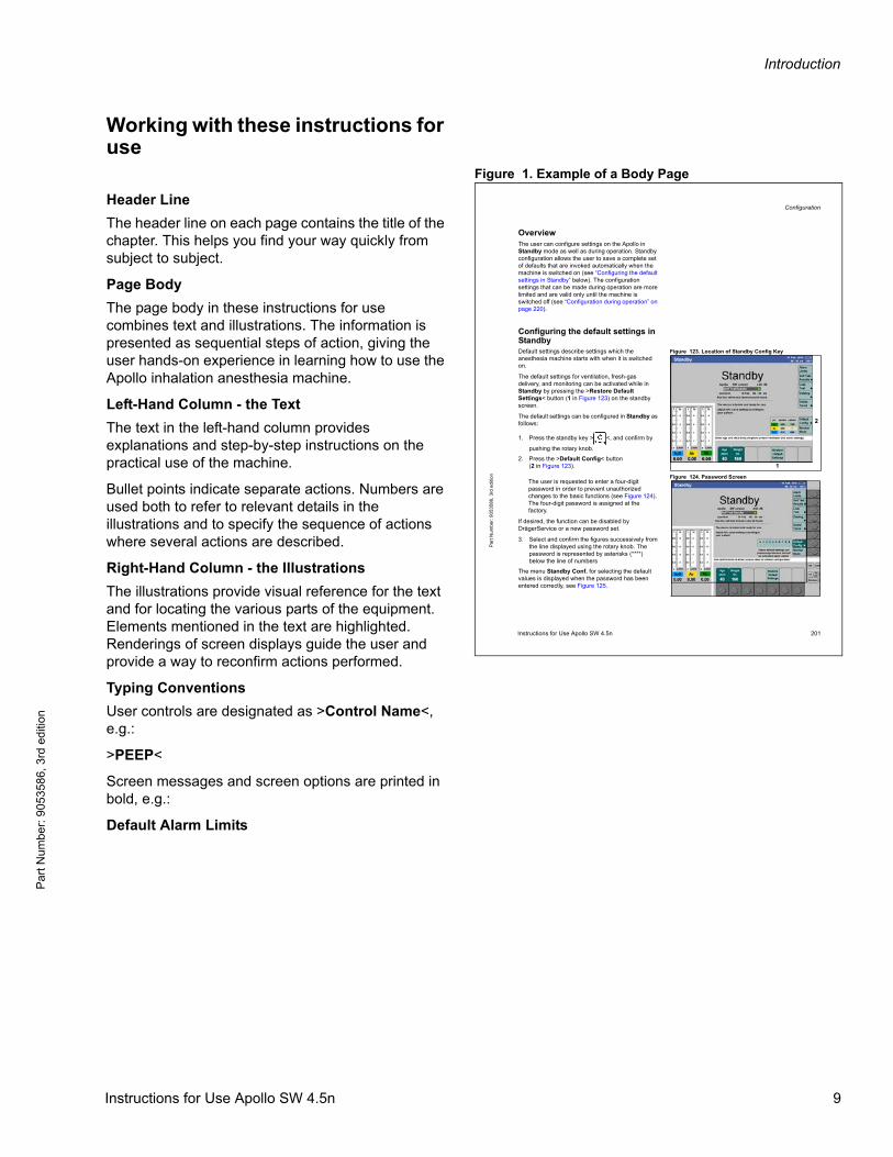
Figure 1. Example of a Body Page
Header Line
The header line on each page contains the title of the chapter. This helps you find your way quickly from subject to subject.
Page Body
The page body in these instructions for use combines text and illustrations. The information is presented as sequential steps of action, giving the user hands-on experience in learning how to use the Apollo inhalation anesthesia machine.
Left-Hand Column - the Text
The text in the left-hand column provides explanations and step-by-step instructions on the practical use of the machine.
Bullet points indicate separate actions. Numbers are used both to refer to relevant details in the illustrations and to specify the sequence of actions where several actions are described.
Right-Hand Column - the Illustrations
The illustrations provide visual reference for the text and for locating the various parts of the equipment. Elements mentioned in the text are highlighted. Renderings of screen displays guide the user and provide a way to reconfirm actions performed.
Typing Conventions
User controls are designated as >Control Name<, e.g.:
>PEEP<
Screen messages and screen options are printed in bold, e.g.:
Default Alarm Limits
Configuration
Instructions for Use Apollo SW 4.5n 201
Par
t Num
ber:
9053
586,
3rd
edi
tion
OverviewThe user can configure settings on the Apollo in Standby mode as well as during operation. Standby configuration allows the user to save a complete set of defaults that are invoked automatically when the machine is switched on (see “Configuring the default settings in Standby” below). The configuration settings that can be made during operation are more limited and are valid only until the machine is switched off (see “Configuration during operation” on page 220).
Configuring the default settings in Standby
Figure 123. Location of Standby Config KeyDefault settings describe settings which the anesthesia machine starts with when it is switched on.
The default settings for ventilation, fresh-gas delivery, and monitoring can be activated while in Standby by pressing the >Restore Default Settings< button (1 in Figure 123) on the standby screen.
The default settings can be configured in Standby as follows:
1. Press the standby key > <, and confirm by
pushing the rotary knob.
2. Press the >Default Config< button(2 in Figure 123).
Figure 124. Password ScreenThe user is requested to enter a four-digit password in order to prevent unauthorized changes to the basic functions (see Figure 124).The four-digit password is assigned at the factory.
If desired, the function can be disabled by DrägerService or a new password set.
3. Select and confirm the figures successively from the line displayed using the rotary knob. The password is represented by asterisks (****) below the line of numbers
The menu Standby Conf. for selecting the default values is displayed when the password has been entered correctly, see Figure 125.
1
2
Instructions for Use Apollo SW 4.5n 9
Introduction
Pa
rt Num
ber: 905358
6, 3rd edition
Use of termsDräger uses the term "Accessory" not only for accessories in the sense of IEC 60601-1, but also for consumable parts, removable parts, and attached parts.
Screen layouts and illustrations of the deviceSchematic renderings of screen layouts and illustrations of the device are used, which may differ in appearance or in configuration from the actual screen images.
Trademarks– Apollo®
– The Dräger® name and logo
– DrägerService®
– Drägersorb®
– D-Vapor®
– Vapor®
– Spirolog®
– SpiroLife®
– WaterLock®
are registered trademarks of Dräger.
– Durasensor®
is a registered trademark of Nellcor.
– OxiMax®
is a registered trademark of Covidien.
– Selectatec®
is a registered trademark of Datex-Ohmeda.
All other products or brand names are trademarks of their respective owners.
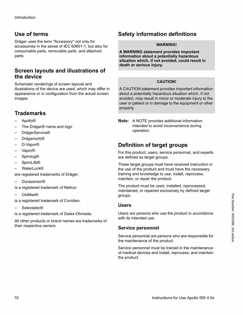
Safety information definitions
Note: A NOTE provides additional information intended to avoid inconvenience during operation.
Definition of target groupsFor this product, users, service personnel, and experts are defined as target groups.
These target groups must have received instruction in the use of the product and must have the necessary training and knowledge to use, install, reprocess, maintain, or repair the product.
The product must be used, installed, reprocessed, maintained, or repaired exclusively by defined target groups.
Users
Users are persons who use the product in accordance with its intended use.
Service personnel
Service personnel are persons who are responsible for the maintenance of the product.
Service personnel must be trained in the maintenance of medical devices and install, reprocess, and maintain the product.
WARNING!
A WARNING statement provides important information about a potentially hazardous situation which, if not avoided, could result in death or serious injury.
CAUTION!
A CAUTION statement provides important information about a potentially hazardous situation which, if not avoided, may result in minor or moderate injury to the user or patient or in damage to the equipment or other property.
10 Instructions for Use Apollo SW 4.5n

Introduction
Par
t Num
ber:
905
3586
, 3rd
edi
tion
Experts
Experts are persons who perform repair or complex maintenance work on the product.
Experts must have the necessary knowledge and experience with complex maintenance work on the product.
Abbreviations and symbolsPlease refer to “Abbreviations” on page 23 and “Symbols” on page 21 for explanations.
Notice
This document is provided for customer information only, and will not be updated or exchanged without customer request.
General safety informationThe following WARNING and CAUTION statements apply to general operation of the medical device.
WARNING and CAUTION statements specific to subsystems or particular features of the medical device appear in the respective sections of these instructions for use or in the Instructions for Use of another product being used with this medical device.
Strictly follow these Instructions for Use
Maintenance
Accessories
Note: Strictly observe the instructions for use of all accessories such as:
– Water traps
– Flow sensors
– CLIC adapter
– CLIC absorber
– Soda lime
– Breathing hoses
– Masks
– Filters
– Endotracheal suction
– Vaporizer
– Manual resuscitator
– AGSS terminal unit
WARNING!
Risk of incorrect operation and of incorrect use
Any use of the medical device requires full understanding and strict observation of all sections of these instructions for use. The medical device must only be used for the purpose specified under “Indications and contraindications” on page 16 and “Intended Use” on page 16 and in conjunction with appropriate patient monitoring (see page 18).
Strictly observe all WARNING and CAUTION statements throughout these instructions for use and the information on medical device labels. Failure to observe these safety information statements constitutes a use of the medical device that is inconsistent with its intended use.
WARNING!
Risk of medical device failure and of patient injury
The medical device must be inspected and serviced regularly by service personnel. Repair and complex maintenance carried out on the medical device must be performed by experts.
If the above is not complied with, medical device failure and patient injury may occur. Observe chapter “Cleaning and Maintenance”.
Dräger recommends that a service contract is obtained with DrägerService and that all repairs are performed by DrägerService. For maintenance Dräger recommends the use of authentic Dräger repair parts.
WARNING!
Risk due to incompatible accessories
Dräger has tested only the compatibility of accessories listed in the current list of accessories. If other, incompatible accessories are used, there is a risk of patient injury due to medical device failure.
Dräger recommends that the medical device is only used together with accessories listed in the current list of accessories.
Instructions for Use Apollo SW 4.5n 11
Introduction
Pa
rt Num
ber: 905358
6, 3rd edition
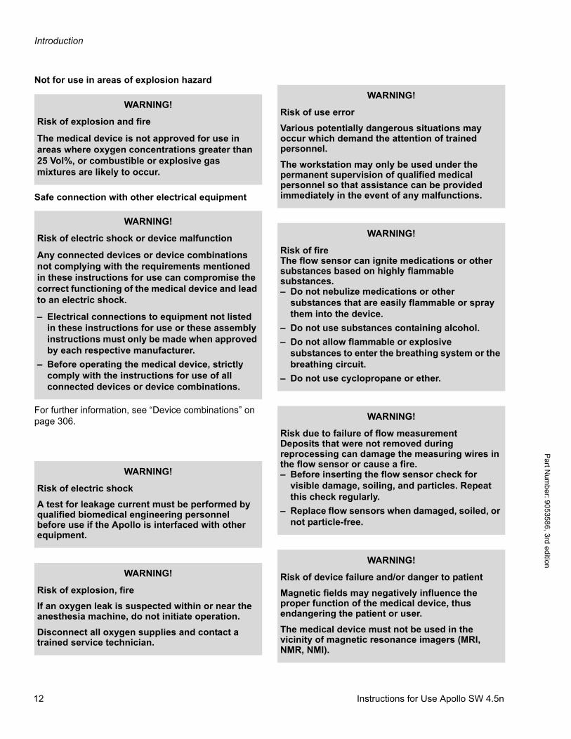
Not for use in areas of explosion hazard
Safe connection with other electrical equipment
For further information, see “Device combinations” on page 306.
WARNING!
Risk of explosion and fire
The medical device is not approved for use in areas where oxygen concentrations greater than 25 Vol%, or combustible or explosive gas mixtures are likely to occur.
WARNING!
Risk of electric shock or device malfunction
Any connected devices or device combinations not complying with the requirements mentioned in these instructions for use can compromise the correct functioning of the medical device and lead to an electric shock.
– Electrical connections to equipment not listed in these instructions for use or these assembly instructions must only be made when approved by each respective manufacturer.
– Before operating the medical device, strictly comply with the instructions for use of all connected devices or device combinations.
WARNING!
Risk of electric shock
A test for leakage current must be performed by qualified biomedical engineering personnel before use if the Apollo is interfaced with other equipment.
WARNING!
Risk of explosion, fire
If an oxygen leak is suspected within or near the anesthesia machine, do not initiate operation.
Disconnect all oxygen supplies and contact a trained service technician.
WARNING!
Risk of use error
Various potentially dangerous situations may occur which demand the attention of trained personnel.
The workstation may only be used under the permanent supervision of qualified medical personnel so that assistance can be provided immediately in the event of any malfunctions.
WARNING!
Risk of fireThe flow sensor can ignite medications or other substances based on highly flammable substances.– Do not nebulize medications or other
substances that are easily flammable or spray them into the device.
– Do not use substances containing alcohol.
– Do not allow flammable or explosive substances to enter the breathing system or the breathing circuit.
– Do not use cyclopropane or ether.
WARNING!
Risk due to failure of flow measurementDeposits that were not removed during reprocessing can damage the measuring wires in the flow sensor or cause a fire.– Before inserting the flow sensor check for
visible damage, soiling, and particles. Repeat this check regularly.
– Replace flow sensors when damaged, soiled, or not particle-free.
WARNING!
Risk of device failure and/or danger to patient
Magnetic fields may negatively influence the proper function of the medical device, thus endangering the patient or user.
The medical device must not be used in the vicinity of magnetic resonance imagers (MRI, NMR, NMI).
12 Instructions for Use Apollo SW 4.5n
Introduction
Par
t Num
ber:
905
3586
, 3rd
edi
tion
Information on electromagnetic compatibility
General information on electromagnetic compatibility (EMC) according to international EMC standard IEC 60601-1-2:
Medical electrical equipment is subject to special precautionary measures concerning electromagnetic compatibility (EMC) and must be installed and put into operation in accordance with the EMC information provided (see page 303).
Portable and mobile radio frequency communication equipment can affect medical electrical equipment.
Patient safety
The design of the medical device, the accompanying documentation, and the labeling on the medical device are based on the assumption that the purchase and the use of the medical device are restricted to persons familiar with the most important inherent characteristics of the medical device.
Instructions and WARNING and CAUTION statements are therefore largely limited to the specifics of the Dräger medical device.
The instructions for use do not contain any information on the following points:
– Risks that are obvious to users
– Consequences of obvious improper use of the medical device
– Potentially negative effects on patients with different underlying diseases
Medical device modification or misuse can be dangerous.
Patient monitoring
The user of the medical device is responsible for choosing a suitable patient monitoring system that provides appropriate information on medical device performance and patient condition.
Patient safety may be achieved by a wide variety of means ranging from electronic surveillance of medical device performance and patient condition to direct observation of clinical signs.
The responsibility for selection the best level of patient monitoring lies solely with the user of the medical device.
WARNING!
Risk of electric shock
Do not connect connectors with an ESD warning symbol and do not touch their pins without implementing ESD protective measures. Such protective
measures can include antistatic clothing and shoes, touching a potential equalization pin before and during connection of the pins, or using electrically insulating and antistatic gloves.
All users concerned must be instructed in these ESD protective measures.
WARNING!
Risk of electric shock
Connecting devices to the auxiliary outlets of the anesthesia machine can cause an increase in leakage current beyond permissible values if the
protective conductor of a device fails.
Check the leakage current when connecting devices to the auxiliary outlets. If connecting a device (or devices) increases the leakage current to a value which exceeds the permissible value, do not use the auxiliary outlets of the anesthesia machine: use a separate wall socket.
The system must fulfill the requirements for medical electrical equipment in accordance with the relevant standards, see page 308.
CAUTION!
Risk of patient injury
Do not make therapeutic decisions based solely on individual measured values and monitoring parameters.
Instructions for Use Apollo SW 4.5n 13
Introduction
Pa
rt Num
ber: 905358
6, 3rd edition
Sterile accessories
Installing accessories
Strictly observe Assembly Instructions and Instructions for Use.
Storing the instructions for use
Training
Training for users is available from the Dräger organization responsible, see www.draeger.com.
Product-specific safety information
CAUTION!
Risk of medical device failure and of patient injury
Do not use sterile-packaged accessories if the packaging has been opened, is damaged, or if there are other signs of non-sterility.
Disposable articles must not be reprocessed and resterilized.
CAUTION!
Install accessories to the basic device in accordance with the Instructions for Use of the basic device. Make sure that there is a safe connection to the basic device system.
CAUTION!
Risk of incorrect use
Instructions for use must be kept accessible to the user.
WARNING!
Risk of malfunctions
Unapproved modifications to the medical device can cause malfunctions.
No modifications must be made to this medical device without the permission of Dräger. Dräger does not accept responsibility for modifications to the device made without the permission of Dräger.
CAUTION!
Risk of patient injury
An incorrect diagnosis or misinterpretation of measured values, or other parameters, may endanger the patient.
Do not base therapy decisions on individual measured values or monitoring parameters only.
WARNING!
Risk of patient injury
If ventilation of the patient is no longer ensured due to an obvious fault in the equipment, the patient must immediately be ventilated with a manual resuscitator.
Always keep a manual resucitator at hand.
WARNING!
Risk of burns
Conductive breathing hoses or face masks may cause burns during HF surgery.
Do not use these types of hoses and masks in combination with HF surgery.
CAUTION!
Risk of mechanical failure
The shock and vibrations caused by transportation may lead to a mechanical failure. The application of a wall or ceiling mounting is designated for buildings.
Do not use the anesthesia machine for mobile facilities such as ambulances, helicopters, or ships.
14 Instructions for Use Apollo SW 4.5n
Introduction
Par
t Num
ber:
905
3586
, 3rd
edi
tion
Functional safety
The essential performance consists of:
– Supplying the anesthesia workstation with O2
If the O2 supply (central supply or gas cylinder) fails, an alarm is issued.
– Supply of the patient with adequately oxygenated breathing gas
If the breathing gas contains insufficient levels of O2, an alarm is issued.
– Patients are not supplied with excessively high anesthetic gas concentrations
If excessively high anesthetic gas concentrations are delivered, an alarm is issued.
– Monitoring the airway pressure and the expiratory minute volume
Alarms are issued depending on the set alarm limits.
CAUTION!
Risk of crushing
Movable parts and attached parts can lead to crushing injuries. Pay special attention to edges, movable parts, and corners when working with the following parts:– Drawers
– Ventilator module
– Doors
– Writing table
– Swivel arms for mounted devices
– Accessories such as gas cylinders, vaporizers, CLIC absorbers, and CLIC adapters
CAUTION!
Risk of device failure
Compressed gas supply (pipeline supply or cylinder): To avoid damaging the device(s) attached to a gas supply, use only medical gases. Pay particular attention to national and international standards regulating the use of medical gases.
WARNING!
Risk due to barely audible alarms
The user must remain within the hearing range of the acoustic alarm signal. This permits quick recognition and handling of the alarm.
Adjust the volume of the alarm signal to the distance from the medical device.
WARNING!
Risk due to a noisy environment
When operating in a noisy environment, the volume of the alarm signals must be adjusted to suit.
Always set the volume of the alarm signal sufficiently high.
Instructions for Use Apollo SW 4.5n 15
Introduction
Pa
rt Num
ber: 905358
6, 3rd edition
Indications and contraindications
Indications
The Apollo is indicated as a continuous flow anesthesia system. The Apollo may be used for manually assisted or automatic ventilation, delivery of gases and anesthetic vapor, and monitoring of oxygen and CO2 concentration, breathing pressure, respiratory volume, and anesthetic agent concentration and identification.
Contraindications
This device has no product-specific contraindications.
The user is responsible for selecting a treatment appropriate to the underlying disease of the patient.
The patient’s condition must be monitored continuously.
Note: Apollo applies medical gases such as oxygen, nitrous oxide, or volatile anesthetic agents.Stricly follow the instructions for use of the medical gases. Pay particular attention to the contraindications of the medical gases used.
Intended Use
The Apollo is an inhalation anesthesia machine for use in operating, induction, and recovery rooms. It can be used with rebreathing systems, semi-closed to virtually closed systems with low flow and minimal flow techniques, and non-rebreathing systems (with the Auxiliary Common Gas Outlet).
It may be used with O2, N2O, and Air supplied by a medical gas pipeline system or by externally mounted gas cylinders. Anesthetic agent can be delivered via vaporizers mounted on the machine.
The Apollo is equipped with a compact breathing system, providing fresh-gas decoupling, PEEP, and pressure limitation. It has an electrically driven and electronically controlled ventilator.
Optional:
As an option, the device can be configured in a way that it must be operated with O2 and Air instead of N2O.
Ventilation modes
– Volume-controlled ventilation in Volume Mode.With activation of:
– Sync. (Synchronization)
– Press. Support (Pressure Support) (optional)
– Pressure-controlled ventilation in Pressure Mode.With activation of:
– Sync. (Synchronization)
– Press. Support (Pressure Support) (optional)
– Manual Ventilation Man.
– Spontaneous Breathing Spont.
– Pressure-Assisted Spontaneous Breathing in Pressure Support CPAP (optional)
– Volume AF (Volume Mode AutoFlow) (optional).With activation of:
– Sync. (Synchronization)
– Press. Support (Pressure Support) (optional).
The following measured values are displayed
– Peak pressure PEAK,Mean pressure PMEAN,Plateau pressure PLAT,Positive end-expiratory pressure PEEP
– Expiratory minute volume MV,Difference between insp. and exp. minute volume MVLEAK,
– Patient compliance CPAT,Tidal volume VT,Breathing rate Freq.
– Inspiratory and expiratory concentration of O2, N2O, anesthetic gas, and CO2
– Difference between insp. and exp. O2 concentration ΔO2
Optional:
– Functional oxygen saturation SpO2,Pulse rate Pulse
The following parameters can be displayed as mini trends1)
– Minute volume CO2, MV*CO2
WARNING!
Risk of device failure and/or danger to patient
If the intended use of this anesthesia machine is not adhered to, it may fail and/or the patient may be endangered.
Use the anesthesia machine only as specified in the intended use of these Instructions for Use.
1) optional
16 Instructions for Use Apollo SW 4.5n
Introduction
Par
t Num
ber:
905
3586
, 3rd
edi
tion
– O2 Uptake
– PEEP, patient compliance CPAT
The following parameters are displayed as curves
– Airway pressure PAW
– Inspiratory and expiratory flow
– Inspiratory and expiratory concentration of O2, CO2, and anesthetic gas
Instructions for Use Apollo SW 4.5n 17
Introduction
Pa
rt Num
ber: 905358
6, 3rd edition
Optional:
– Plethysmogram
– PAW-V loops and V-Flow loops
The following parameters are displayed as bar graphs
– Inspiratory tidal volume, expiratory tidal volume, and leakage tidal volume
– Volumeter
– Pressure
– Low-flow wizard for indicating fresh-gas utilization (optional)
Trends showing the measured values over time and a logbook are also available.
Monitoring
By means of adjustable alarm limits which can automatically be adapted to the momentary ventilation situation.
With monitoring for
– Airway pressure PAW
– Expiratory minute volume MV
– Apnea
– Inspiratory and expiratory anesthetic gas concentration
– Detection of anesthetic gas mixtures (simultaneous detection of up to two anesthetic agents)
– Inspiratory O2 and N2O concentrations
– Inspiratory and expiratory CO2 concentrations
– Special alarm response in Bypass Mode
– Automatic agent alarm activation for multiples of MAC (xMAC)
Optional:
– Oxygen saturation
– Pulse rate Pulse
Environment of useApollo is designed for use in areas in which therapeutic or diagnostic procedures can be performed.
Do not use Apollo in the following environments:
– Outside buildings
– On intensive care units
– During patient transport
– In vehicles, airplanes, or helicopters
WARNING!
Risk of explosion and fire
The medical device is not approved for use in areas where oxygen concentrations greater than 25 Vol%, or combustible or explosive gas mixtures are likely to occur.
WARNING!
Risk of device failure and/or danger to patient
Magnetic fields may negatively influence the proper function of the medical device, thus endangering the patient or user.
The medical device must not be used in the vicinity of magnetic resonance imagers (MRI, NMR, NMI).
18 Instructions for Use Apollo SW 4.5n
Introduction
Par
t Num
ber:
905
3586
, 3rd
edi
tion
Additional functions
MEDIBUS/MEDIBUS.X Protocol
MEDIBUS and MEDIBUS.X are software protocols for use in transferring data between Apollo and an external medical or non-medical device (e.g. hemodynamic monitors, data management systems, or a Windows-based computer) via the RS-232 interface see:
– 9037426, 6th edition or higher
or
– 9052608, third edition or higher.
WARNING!
Risk of patient injury
Data transferred via MEDIBUS/MEDIBUS.X interfaces are for information only and are not intended as a basis for diagnosis or therapy decisions. The data accessible via this interface are not intended for a decentralized alarm system in accordance with IEC60601-1-8:2012 (in the sense of remote monitoring).
WARNING!
Risk of electric shock
Connecting devices to the auxiliary outlets of the anesthesia machine can cause an increase in leakage current beyond permissible values if the protective conductor of a device fails.
Check the leakage current when connecting devices to the auxiliary outlets. If connecting a device (or devices) increases the leakage current to a value which exceeds the permissible value, do not use the auxiliary outlets of the anesthesia machine: use a separate wall socket.
The system must fulfill the requirements for medical electrical equipment in accordance with the relevant standards, see page 308.
Instructions for Use Apollo SW 4.5n 19
Introduction
Pa
rt Num
ber: 905358
6, 3rd edition
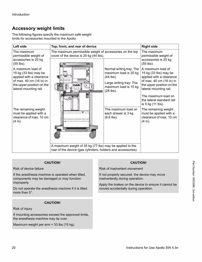
Accessory weight limitsThe following figures specify the maximum safe weight limits for accessories mounted to the Apollo.
Left side Top, front, and rear of device Right side
The maximum permissible weight of accessories is 25 kg (55 lbs).
The maximum permissible weight of accessories on the top cover of the device is 20 kg (44 lbs).
The maximum permissible weight of accessories is 25 kg (55 lbs).
A maximum load of 15 kg (33 lbs) may be applied with a clearance of max. 40 cm (16 in) in the upper position on the lateral mounting rail.
Normal writing tray: The maximum load is 20 kg (44 lbs).
Large writing tray: The maximum load is 15 kg (28 lbs).
A maximum load of 15 kg (33 lbs) may be applied with a clearance of max. 40 cm (16 in) in the upper position on the lateral mounting rail.
The maximum load on the lateral standard rail is 5 kg (11 lbs).
The remaining weight must be applied with a clearance of max. 10 cm (4 in).
The maximum load on each drawer is 3 kg (6.6 lbs).
The remaining weight must be applied with a clearance of max. 10 cm (4 in).
A maximum weight of 35 kg (77 lbs) may be applied to the rear of the device (gas cylinders, holders and accessories).
CAUTION!
Risk of device failure
If the anesthesia machine is operated when tilted, components may be damaged or may function improperly.
Do not operate the anesthesia machine if it is tilted more than 5°.
CAUTION!
Risk of injury
If mounting accessories exceed the approved limits, the anesthesia machine may tip over.
Maximum weight per arm = 33 lbs (15 kg).
CAUTION!
Risk of inadvertent movement
If not properly secured, the device may move inadvertently during operation.
Apply the brakes on the device to ensure it cannot be moved accidentally during operation.
20 Instructions for Use Apollo SW 4.5n
Introduction
Par
t Num
ber:
905
3586
, 3rd
edi
tion
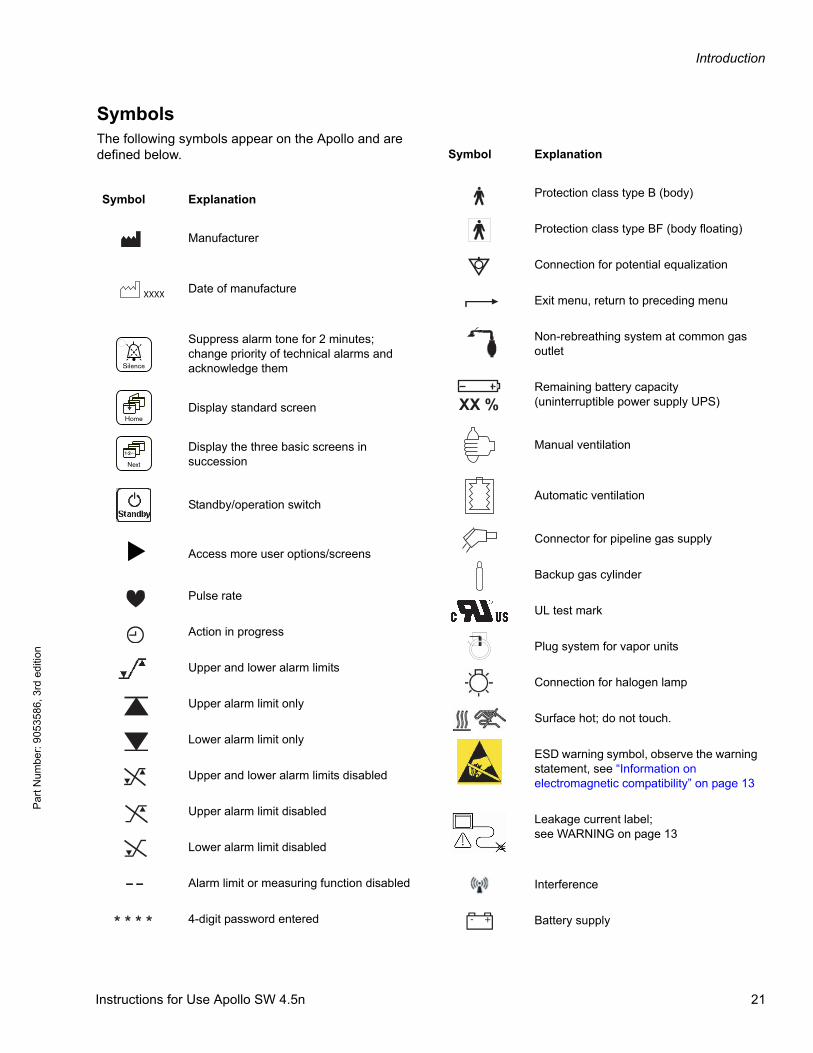
SymbolsThe following symbols appear on the Apollo and are defined below.
Symbol Explanation
Manufacturer
Date of manufacture
Suppress alarm tone for 2 minutes; change priority of technical alarms and acknowledge them
Display standard screen
Display the three basic screens in succession
Standby/operation switch
Access more user options/screens
Pulse rate
Action in progress
Upper and lower alarm limits
Upper alarm limit only
Lower alarm limit only
Upper and lower alarm limits disabled
Upper alarm limit disabled
Lower alarm limit disabled
Alarm limit or measuring function disabled
4-digit password entered
XXXX
_
>
<
Protection class type B (body)
Protection class type BF (body floating)
Connection for potential equalization
Exit menu, return to preceding menu
Non-rebreathing system at common gas outlet
Remaining battery capacity(uninterruptible power supply UPS)
Manual ventilation
Automatic ventilation
Connector for pipeline gas supply
Backup gas cylinder
UL test mark
Plug system for vapor units
Connection for halogen lamp
Surface hot; do not touch.
ESD warning symbol, observe the warning statement, see “Information on electromagnetic compatibility” on page 13
Leakage current label; see WARNING on page 13
Interference
Battery supply
Symbol Explanation
Instructions for Use Apollo SW 4.5n 21
Introduction
Pa
rt Num
ber: 905358
6, 3rd edition
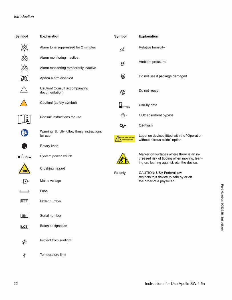
Alarm tone suppressed for 2 minutes
Alarm monitoring inactive
Alarm monitoring temporarily inactive
Apnea alarm disabled
Caution! Consult accompanying documentation!
Caution! (safety symbol)
Consult instructions for use
Warning! Strictly follow these instructions for use
Rotary knob
System power switch
Crushing hazard
Mains voltage
Fuse
Order number
Serial number
Batch designation
Protect from sunlight!
Temperature limit
Symbol Explanation
REF
SN
LOT
Relative humidity
Ambient pressure
Do not use if package damaged
Do not reuse
Use-by date
CO2 absorbent bypass
O2-Flush
Label on devices fitted with the "Operation without nitrous oxide" option.
Marker on surfaces where there is an in-creased risk of tipping when moving, lean-ing on, leaning against, etc. the device.
Rx only CAUTION: USA Federal lawrestricts this device to sale by or onthe order of a physician.
Symbol Explanation
YYYY-MM
+
Operation withoutnitrous oxide!
22 Instructions for Use Apollo SW 4.5n
Introduction
Par
t Num
ber:
905
3586
, 3rd
edi
tion
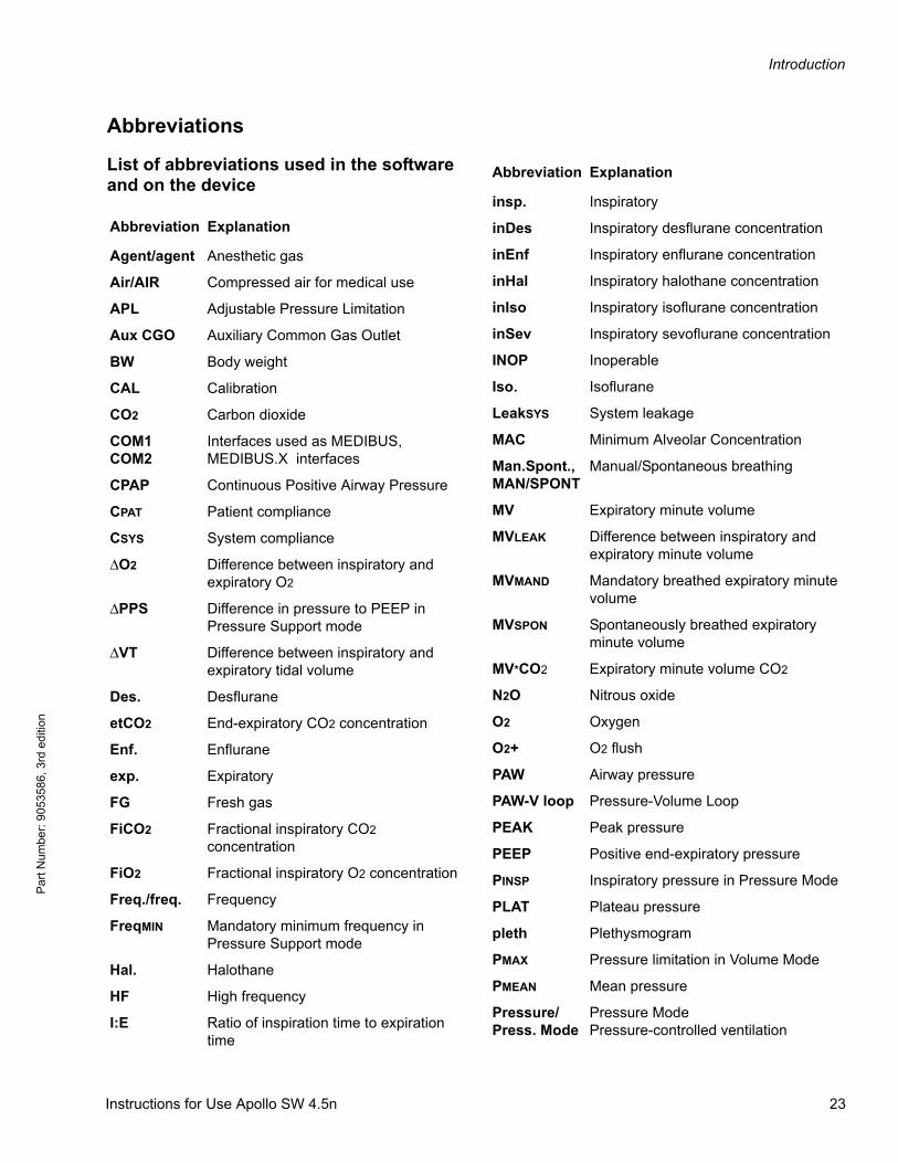
Abbreviations
List of abbreviations used in the software and on the device
Abbreviation Explanation
Agent/agent Anesthetic gas
Air/AIR Compressed air for medical use
APL Adjustable Pressure Limitation
Aux CGO Auxiliary Common Gas Outlet
BW Body weight
CAL Calibration
CO2 Carbon dioxide
COM1COM2
Interfaces used as MEDIBUS, MEDIBUS.X interfaces
CPAP Continuous Positive Airway Pressure
CPAT Patient compliance
CSYS System compliance
ΔO2 Difference between inspiratory and expiratory O2
ΔPPS Difference in pressure to PEEP in Pressure Support mode
ΔVT Difference between inspiratory and expiratory tidal volume
Des. Desflurane
etCO2 End-expiratory CO2 concentration
Enf. Enflurane
exp. Expiratory
FG Fresh gas
FiCO2 Fractional inspiratory CO2 concentration
FiO2 Fractional inspiratory O2 concentration
Freq./freq. Frequency
FreqMIN Mandatory minimum frequency in Pressure Support mode
Hal. Halothane
HF High frequency
I:E Ratio of inspiration time to expiration time
insp. Inspiratory
inDes Inspiratory desflurane concentration
inEnf Inspiratory enflurane concentration
inHal Inspiratory halothane concentration
inIso Inspiratory isoflurane concentration
inSev Inspiratory sevoflurane concentration
INOP Inoperable
Iso. Isoflurane
LeakSYS System leakage
MAC Minimum Alveolar Concentration
Man.Spont., MAN/SPONT
Manual/Spontaneous breathing
MV Expiratory minute volume
MVLEAK Difference between inspiratory and expiratory minute volume
MVMAND Mandatory breathed expiratory minute volume
MVSPON Spontaneously breathed expiratory minute volume
MV*CO2 Expiratory minute volume CO2
N2O Nitrous oxide
O2 Oxygen
O2+ O2 flush
PAW Airway pressure
PAW-V loop Pressure-Volume Loop
PEAK Peak pressure
PEEP Positive end-expiratory pressure
PINSP Inspiratory pressure in Pressure Mode
PLAT Plateau pressure
pleth Plethysmogram
PMAX Pressure limitation in Volume Mode
PMEAN Mean pressure
Pressure/Press. Mode
Pressure ModePressure-controlled ventilation
Abbreviation Explanation
Instructions for Use Apollo SW 4.5n 23
Introduction
Pa
rt Num
ber: 905358
6, 3rd edition
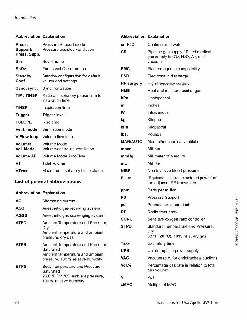
List of general abbreviations
Press. Support/Press. Supp.
Pressure Support modePressure-assisted ventilation
Sev. Sevoflurane
SpO2 Functional O2 saturation
Standby Conf.
Standby configuration for default values and settings
Sync./sync. Synchronization
TIP : TINSP Ratio of inspiratory pause time to inspiration time
TINSP Inspiration time
Trigger Trigger level
TSLOPE Rise time
Vent. mode Ventilation mode
V-Flow loop Volume flow loop
Volume/Vol. Mode
Volume ModeVolume-controlled ventilation
Volume AF Volume Mode AutoFlow
VT Tidal volume
VTINSP Measured inspiratory tidal volume
Abbreviation Explanation
AC Alternating current
AGS Anesthetic gas receiving system
AGSS Anesthetic gas scavenging system
ATPD Ambient Temperature and Pressure, DryAmbient temperature and ambient pressure, dry gas
ATPS Ambient Temperature and Pressure, SaturatedAmbient temperature and ambient pressure, 100 % relative humidity
BTPS Body Temperature and Pressure, Saturated98.6 °F (37 °C), ambient pressure, 100 % relative humidity
Abbreviation Explanation
cmH2O Centimeter of water
CS Pipeline gas supply / Piped medical gas supply for O2, N2O, Air, and vacuum
EMC Electromagnetic compatibility
ESD Electrostatic discharge
HF surgery High-frequency surgery
HME Heat and moisture exchanger
hPa Hectopascal
in Inches
IV Intravenous
kg Kilogram
kPa Kilopascal
lbs. Pounds
MAN/AUTO Manual/mechanical ventilation
mbar Millibar
mmHg Millimeter of Mercury
mL Milliliter
NiBP Non-invasive blood pressure
PEIRP “Equivalent isotropic radiated power” of the adjacent RF transmitter
ppm Parts per million
PS Pressure Support
psi Pounds per square inch
RF Radio frequency
SORC Sensitive oxygen ratio controller
STPD Standard Temperature and Pressure, Dry68 °F (20 °C), 1013 hPa, dry gas
TEXP Expiratory time
UPS Uninterruptible power supply
VAC Vacuum (e.g. for endotracheal suction)
Vol.% Percentage gas rate in relation to total gas volume
V Volt
xMAC Multiple of MAC
Abbreviation Explanation
24 Instructions for Use Apollo SW 4.5n

Introduction
Par
t Num
ber:
905
3586
, 3rd
edi
tion
Units
Note: Throughout these instructions for use:Ventilation pressures: cmH2O = mbar = hPaSupply pressures: bar = kPa x 100
Instructions for Use Apollo SW 4.5n 25

Introduction
Pa
rt Num
ber: 905358
6, 3rd edition
This page intentionally left blank.
26 Instructions for Use Apollo SW 4.5n

System Components
Par
t Num
ber:
905
3586
, 3rd
edi
tion
System Components
ContentsOverview . . . . . . . . . . . . . . . . . . . . . . . . . . . . . . . . . . . . . . . . . . . . . . . . . . . . . . . . . . . . . . . . . . . . . . . . . . . . . . . 29
Machine Front view . . . . . . . . . . . . . . . . . . . . . . . . . . . . . . . . . . . . . . . . . . . . . . . . . . . . . . . . . . . . . . . . . . . . . . 29
Machine Rear view . . . . . . . . . . . . . . . . . . . . . . . . . . . . . . . . . . . . . . . . . . . . . . . . . . . . . . . . . . . . . . . . . . . . . . . 30
Gas supply block . . . . . . . . . . . . . . . . . . . . . . . . . . . . . . . . . . . . . . . . . . . . . . . . . . . . . . . . . . . . . . . . . . . . . . . . 31
Interface panel . . . . . . . . . . . . . . . . . . . . . . . . . . . . . . . . . . . . . . . . . . . . . . . . . . . . . . . . . . . . . . . . . . . . . . . . . . 32
Vaporizers (Optional) . . . . . . . . . . . . . . . . . . . . . . . . . . . . . . . . . . . . . . . . . . . . . . . . . . . . . . . . . . . . . . . . . . . . . 33
Vaporizer exclusion systems . . . . . . . . . . . . . . . . . . . . . . . . . . . . . . . . . . . . . . . . . . . . . . . . . . . . . . . . . . . . . . 34
Dräger Vapor Interlock 2 System (Optional) . . . . . . . . . . . . . . . . . . . . . . . . . . . . . . . . . . . . . . . . . . . . . . . . . . . . . 34
Selectatec (Optional) . . . . . . . . . . . . . . . . . . . . . . . . . . . . . . . . . . . . . . . . . . . . . . . . . . . . . . . . . . . . . . . . . . . . . . 34
Dräger Auto Exclusion 2-Vaporizer Mount (Optional) . . . . . . . . . . . . . . . . . . . . . . . . . . . . . . . . . . . . . . . . . . . . . . 35
Dräger Auto Exclusion 3-Vaporizer Mount (Optional) . . . . . . . . . . . . . . . . . . . . . . . . . . . . . . . . . . . . . . . . . . . . . . 35
APL valve . . . . . . . . . . . . . . . . . . . . . . . . . . . . . . . . . . . . . . . . . . . . . . . . . . . . . . . . . . . . . . . . . . . . . . . . . . . . . . 36
O2 flush . . . . . . . . . . . . . . . . . . . . . . . . . . . . . . . . . . . . . . . . . . . . . . . . . . . . . . . . . . . . . . . . . . . . . . . . . . . . . . . . 37
Auxiliary oxygen flow meter . . . . . . . . . . . . . . . . . . . . . . . . . . . . . . . . . . . . . . . . . . . . . . . . . . . . . . . . . . . . . . . 37
Writing table . . . . . . . . . . . . . . . . . . . . . . . . . . . . . . . . . . . . . . . . . . . . . . . . . . . . . . . . . . . . . . . . . . . . . . . . . . . . 39
Gas flow diagram . . . . . . . . . . . . . . . . . . . . . . . . . . . . . . . . . . . . . . . . . . . . . . . . . . . . . . . . . . . . . . . . . . . . . . . . 39
Instructions for Use Apollo SW 4.5n 27

System Components
Pa
rt Num
ber: 905358
6, 3rd edition
This page intentionally left blank.
28 Instructions for Use Apollo SW 4.5n

System Components
Par
t Num
ber:
905
3586
, 3rd
edi
tion
OverviewThis chapter identifies the major physical components of the Apollo anesthesia machine and provides a brief description of specific parts.
Machine Front view
23
5678
9
10
11
12
15
16
17
18
19
20
221
4
13
14
21
1 Lighting control (dimmer) location 12 Central brake
2 Screen with user interface 13 Footrest
3 Rotary knob 14 Drawers (2) (for storage)
4 Fresh-gas flow controls: O2, Air, N2O 15 Anesthetic gas receiving system AGS (optional)
5 Mains power switch 16 Endotracheal aspiration system (optional)
6 Total flow meter 17 Flexible breathing bag arm
7 O2 flush button O2+ 18 Auxiliary oxygen flow meter
8 Writing table 19 Water trap with sample line connection
9 Breathing system 20 Vaporizer units with interlock system (optional)
10 Release button for ventilator module 21 Auxiliary AC outlet (for Desflurane vaporizer)
11 Absorber (optional: disposable CLIC absorber) 22 Top shelf (for external monitors)
Instructions for Use Apollo SW 4.5n 29
System Components
Pa
rt Num
ber: 905358
6, 3rd edition
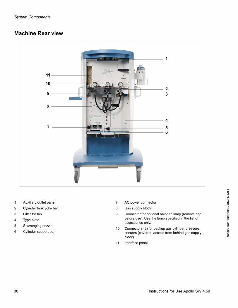
Machine Rear view
1
23
657
8
9
10
11
4
1 Auxiliary outlet panel
2 Cylinder tank yoke bar
3 Filter for fan
4 Type plate
5 Scavenging nozzle
6 Cylinder support bar
7 AC power connector
8 Gas supply block
9 Connector for optional halogen lamp (remove cap before use). Use the lamp specified in the list of accessories only.
10 Connectors (3) for backup gas cylinder pressure sensors (covered; access from behind gas supply block)
11 Interface panel
30 Instructions for Use Apollo SW 4.5n
System Components
Par
t Num
ber:
905
3586
, 3rd
edi
tion
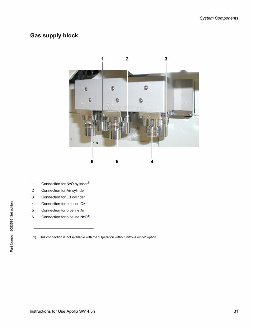
Gas supply block
1 Connection for N2O cylinder1)
1) This connection is not available with the "Operation without nitrous oxide" option.
2 Connection for Air cylinder
3 Connection for O2 cylinder
4 Connection for pipeline O2
5 Connection for pipeline Air
6 Connection for pipeline N2O1)
2 3
56 4
1
Instructions for Use Apollo SW 4.5n 31
System Components
Pa
rt Num
ber: 905358
6, 3rd edition
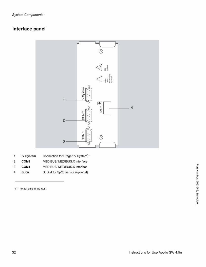
Interface panel
CO
M 1
CO
M 2
IV S
yste
m
SpO
2!
Cau
tion!
Con
sult
Acco
mpa
nyin
gD
ocum
ents
ESD
Sens
itivi
ty4
3
2
1
1 IV System Connection for Dräger IV System1)
2 COM2 MEDIBUS/ MEDIBUS.X interface
3 COM1 MEDIBUS/ MEDIBUS.X interface
4 SpO2 Socket for SpO2 sensor (optional)
1) not for sale in the U.S.
32 Instructions for Use Apollo SW 4.5n
System Components
Par
t Num
ber:
905
3586
, 3rd
edi
tion
Vaporizers (Optional)Note: Before operating the vaporizer, pay special
attention to the Instructions for Use of the vaporizer being used. Note especially the vaporizer flow limits.
The Dräger Vapor anesthetic agent vaporizers are used to enrich the fresh gas with a precisely metered quantity of vapor from the liquid anesthetic agent being used, i.e. Isoflurane, Halothane, Enflurane, Sevoflurane, or Desflurane.
When using a Desflurane vaporizer, it must be connected to mains power. The auxiliary power outlet (IEC/EN 60320-2-2/F) near the vaporizer exclusion system is provided for that purpose.
The vaporizers being used must comply with standard ISO 8835-4. If the internal gas measurement system fails, an independent measurement system complying with ISO 21647 must be used
WARNING!
Risk of patient injury
Risk of ambient air contamination
To prevent vaporizer leakage, which may lead to low fresh-gas delivery, impaired manual ventilation, or contamination of the ambient air, the D-Vapor must be mounted very carefully.
Avoid catching the D-Vapor power cable behind/underneath the housing. Make sure that the D-Vapor is upright. Always perform a leak test after mounting the vaporizer.
CAUTION!
Risk of patient injury
If the vaporizer is not correctly mounted, the fresh-gas flow will not be supplied with anesthetic agent and the patient will not receive the correct anesthesia.
Always double-check the position of the vaporizer, make sure it is correctly mounted and do not mount the vaporizer park holder close to the operable vaporizer.
Instructions for Use Apollo SW 4.5n 33
System Components
Pa
rt Num
ber: 905358
6, 3rd edition
Vaporizer exclusion systemsThe exclusion systems available for the Apollo are described below.
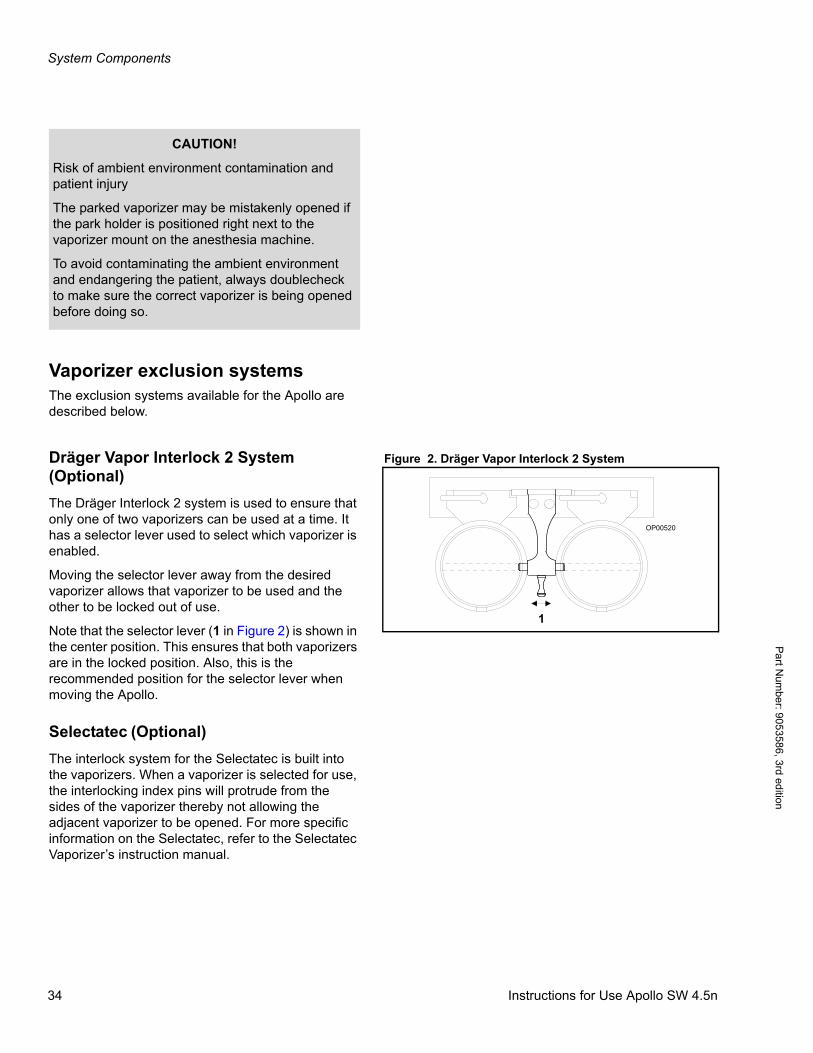
Figure 2. Dräger Vapor Interlock 2 SystemDräger Vapor Interlock 2 System (Optional)
The Dräger Interlock 2 system is used to ensure that only one of two vaporizers can be used at a time. It has a selector lever used to select which vaporizer is enabled.
Moving the selector lever away from the desired vaporizer allows that vaporizer to be used and the other to be locked out of use.
Note that the selector lever (1 in Figure 2) is shown in the center position. This ensures that both vaporizers are in the locked position. Also, this is the recommended position for the selector lever when moving the Apollo.
Selectatec (Optional)
The interlock system for the Selectatec is built into the vaporizers. When a vaporizer is selected for use, the interlocking index pins will protrude from the sides of the vaporizer thereby not allowing the adjacent vaporizer to be opened. For more specific information on the Selectatec, refer to the Selectatec Vaporizer’s instruction manual.
CAUTION!
Risk of ambient environment contamination and patient injury
The parked vaporizer may be mistakenly opened if the park holder is positioned right next to the vaporizer mount on the anesthesia machine.
To avoid contaminating the ambient environment and endangering the patient, always doublecheck to make sure the correct vaporizer is being opened before doing so.
OP00520
1
34 Instructions for Use Apollo SW 4.5n
System Components
Par
t Num
ber:
905
3586
, 3rd
edi
tion
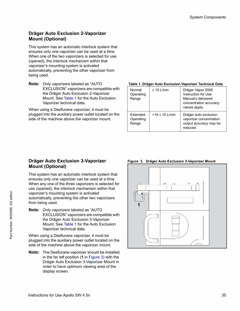
Dräger Auto Exclusion 2-Vaporizer Mount (Optional)
This system has an automatic interlock system that ensures only one vaporizer can be used at a time. When one of the two vaporizers is selected for use (opened), the interlock mechanism within that vaporizer’s mounting system is activated automatically, preventing the other vaporizer from being used.
Table 1. Dräger Auto Exclusion Vaporizer Technical DataNote: Only vaporizers labeled as “AUTO EXCLUSION” vaporizers are compatible with the Dräger Auto Exclusion 2-Vaporizer Mount. See Table 1 for the Auto Exclusion Vaporizer technical data.
When using a Desflurane vaporizer, it must be plugged into the auxiliary power outlet located on the side of the machine above the vaporizer mount.
Figure 3. Dräger Auto Exclusion 3-Vaporizer MountDräger Auto Exclusion 3-Vaporizer Mount (Optional)
This system has an automatic interlock system that ensures only one vaporizer can be used at a time. When any one of the three vaporizers is selected for use (opened), the interlock mechanism within that vaporizer’s mounting system is activated automatically, preventing the other two vaporizers from being used.
Note: Only vaporizers labeled as “AUTO EXCLUSION” vaporizers are compatible with the Dräger Auto Exclusion 3-Vaporizer Mount. See Table 1 for the Auto Exclusion Vaporizer technical data.
When using a Desflurane vaporizer, it must be plugged into the auxiliary power outlet located on the side of the machine above the vaporizer mount.
Note: The Desflurane vaporizer should be installed in the far left position (1 in Figure 3) with the Dräger Auto Exclusion 3-Vaporizer Mount in order to have optimum viewing area of the display screen.
Normal Operating Range
≤ 10 L/min Dräger Vapor 2000 Instruction for Use Manual’s delivered concentration accuracy values apply.
Extended Operating Range
>10 ≤ 15 L/min Dräger auto exclusion vaporizer concentration output accuracy may be reduced.
1
Instructions for Use Apollo SW 4.5n 35
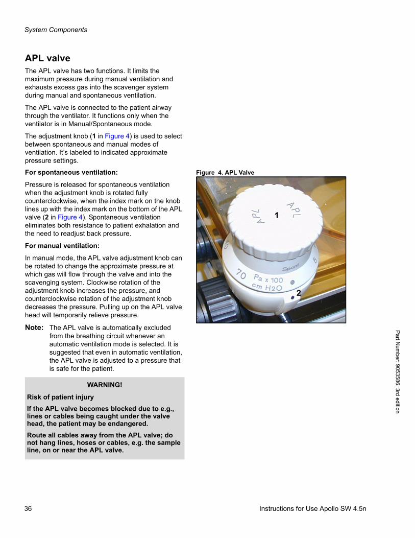
System Components
Pa
rt Num
ber: 905358
6, 3rd edition
APL valveThe APL valve has two functions. It limits the maximum pressure during manual ventilation and exhausts excess gas into the scavenger system during manual and spontaneous ventilation.
The APL valve is connected to the patient airway through the ventilator. It functions only when the ventilator is in Manual/Spontaneous mode.
The adjustment knob (1 in Figure 4) is used to select between spontaneous and manual modes of ventilation. It’s labeled to indicated approximate pressure settings.
Figure 4. APL ValveFor spontaneous ventilation:
Pressure is released for spontaneous ventilation when the adjustment knob is rotated fully counterclockwise, when the index mark on the knob lines up with the index mark on the bottom of the APL valve (2 in Figure 4). Spontaneous ventilation eliminates both resistance to patient exhalation and the need to readjust back pressure.
For manual ventilation:
In manual mode, the APL valve adjustment knob can be rotated to change the approximate pressure at which gas will flow through the valve and into the scavenging system. Clockwise rotation of the adjustment knob increases the pressure, and counterclockwise rotation of the adjustment knob decreases the pressure. Pulling up on the APL valve head will temporarily relieve pressure.
Note: The APL valve is automatically excluded from the breathing circuit whenever an automatic ventilation mode is selected. It is suggested that even in automatic ventilation, the APL valve is adjusted to a pressure that is safe for the patient.
1
2
WARNING!
Risk of patient injury
If the APL valve becomes blocked due to e.g., lines or cables being caught under the valve head, the patient may be endangered.
Route all cables away from the APL valve; do not hang lines, hoses or cables, e.g. the sample line, on or near the APL valve.
36 Instructions for Use Apollo SW 4.5n
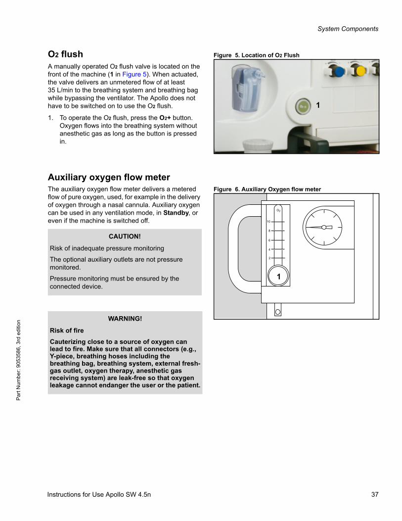
System Components
Par
t Num
ber:
905
3586
, 3rd
edi
tion
Figure 5. Location of O2 FlushO2 flushA manually operated O2 flush valve is located on the front of the machine (1 in Figure 5). When actuated, the valve delivers an unmetered flow of at least35 L/min to the breathing system and breathing bag while bypassing the ventilator. The Apollo does not have to be switched on to use the O2 flush.
1. To operate the O2 flush, press the O2+ button. Oxygen flows into the breathing system without anesthetic gas as long as the button is pressed in.
Auxiliary oxygen flow meterFigure 6. Auxiliary Oxygen flow meterThe auxiliary oxygen flow meter delivers a metered
flow of pure oxygen, used, for example in the delivery of oxygen through a nasal cannula. Auxiliary oxygen can be used in any ventilation mode, in Standby, or even if the machine is switched off.
1
2
4
6
8
10
O2
1
CAUTION!
Risk of inadequate pressure monitoring
The optional auxiliary outlets are not pressure monitored.
Pressure monitoring must be ensured by the connected device.
WARNING!
Risk of fire
Cauterizing close to a source of oxygen can lead to fire. Make sure that all connectors (e.g., Y-piece, breathing hoses including the breathing bag, breathing system, external fresh-gas outlet, oxygen therapy, anesthetic gas receiving system) are leak-free so that oxygen leakage cannot endanger the user or the patient.
Instructions for Use Apollo SW 4.5n 37

System Components
Pa
rt Num
ber: 905358
6, 3rd edition
When finishing oxygen therapy, make sure the flow tube is completely closed:
1. Turn the flow knob (1 in Figure 6) clockwise until it is completely closed to cut off the oxygen flow.
WARNING!
Risk of patient injury
If the patient is connected to the auxiliary oxygen outlet without a means of pressure relief, high pressure will be applied and the patient endangered.
Do not connect the patient directly to the auxiliary oxygen outlet without ensuring a means of pressure relief.
38 Instructions for Use Apollo SW 4.5n
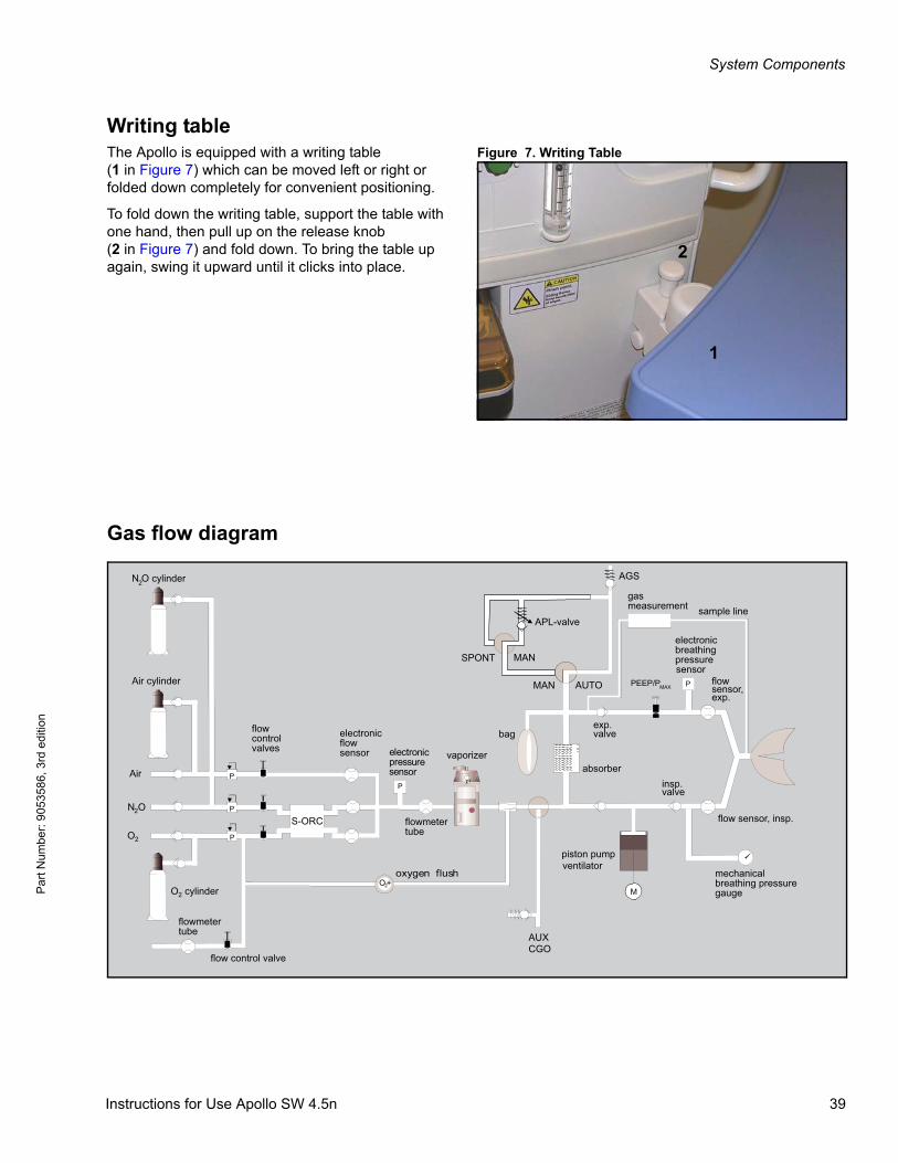
System Components
Par
t Num
ber:
905
3586
, 3rd
edi
tion
Writing tableFigure 7. Writing TableThe Apollo is equipped with a writing table
(1 in Figure 7) which can be moved left or right or folded down completely for convenient positioning.
To fold down the writing table, support the table with one hand, then pull up on the release knob(2 in Figure 7) and fold down. To bring the table up again, swing it upward until it clicks into place.
Gas flow diagram
1
2
Instructions for Use Apollo SW 4.5n 39

System Components
Pa
rt Num
ber: 905358
6, 3rd edition
This page intentionally left blank.
40 Instructions for Use Apollo SW 4.5n
User Interface
Par
t Num
ber:
905
3586
, 3rd
edi
tion
User Interface
ContentsOverview . . . . . . . . . . . . . . . . . . . . . . . . . . . . . . . . . . . . . . . . . . . . . . . . . . . . . . . . . . . . . . . . . . . . . . . . . . . . . . . 43
Main screen display . . . . . . . . . . . . . . . . . . . . . . . . . . . . . . . . . . . . . . . . . . . . . . . . . . . . . . . . . . . . . . . . . . . . . . 43
User controls . . . . . . . . . . . . . . . . . . . . . . . . . . . . . . . . . . . . . . . . . . . . . . . . . . . . . . . . . . . . . . . . . . . . . . . . . . . 45
Standard function keys . . . . . . . . . . . . . . . . . . . . . . . . . . . . . . . . . . . . . . . . . . . . . . . . . . . . . . . . . . . . . . . . . . . . . 45
Rotary knob . . . . . . . . . . . . . . . . . . . . . . . . . . . . . . . . . . . . . . . . . . . . . . . . . . . . . . . . . . . . . . . . . . . . . . . . . . . . . 45
Standby key . . . . . . . . . . . . . . . . . . . . . . . . . . . . . . . . . . . . . . . . . . . . . . . . . . . . . . . . . . . . . . . . . . . . . . . . . . . . . 46
Flow control knobs . . . . . . . . . . . . . . . . . . . . . . . . . . . . . . . . . . . . . . . . . . . . . . . . . . . . . . . . . . . . . . . . . . . . . . . . 46
Ventilation control keys . . . . . . . . . . . . . . . . . . . . . . . . . . . . . . . . . . . . . . . . . . . . . . . . . . . . . . . . . . . . . . . . . . . . . 47
Monitoring/Configuration control keys . . . . . . . . . . . . . . . . . . . . . . . . . . . . . . . . . . . . . . . . . . . . . . . . . . . . . . . . . 48
LED indicators . . . . . . . . . . . . . . . . . . . . . . . . . . . . . . . . . . . . . . . . . . . . . . . . . . . . . . . . . . . . . . . . . . . . . . . . . . 49
Screen colors . . . . . . . . . . . . . . . . . . . . . . . . . . . . . . . . . . . . . . . . . . . . . . . . . . . . . . . . . . . . . . . . . . . . . . . . . . . 49
Menu structure overview . . . . . . . . . . . . . . . . . . . . . . . . . . . . . . . . . . . . . . . . . . . . . . . . . . . . . . . . . . . . . . . . . . 51
Instructions for Use Apollo SW 4.5n 41

User Interface
Pa
rt Num
ber: 905358
6, 3rd edition
This page intentionally left blank.
42 Instructions for Use Apollo SW 4.5n
User Interface
Par
t Num
ber:
905
3586
, 3rd
edi
tion
OverviewThis chapter provides a description of the Apollo user interface, which enables you to view and change monitoring, ventilation, and status information using keys and the rotary knob.
Main screen display
The screen display is organized into four functional areas:
– Gas measurement
– Monitoring
– Fresh-gas delivery
– Ventilation
Figure 8 illustrates the general functional areas and identifies the following smaller screen elements:
Instructions for Use Apollo SW 4.5n 43
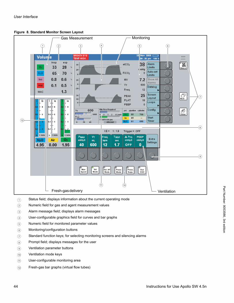
User Interface
Pa
rt Num
ber: 905358
6, 3rd edition
Figure 8. Standard Monitor Screen Layout
Vol. AFMode
VolMode
ManSpont
PressMode
Press.Supp.
AuxCGO
Gas Measurement Monitoring
deliveryFresh-gas Ventilation
8
12
9
7
1011
654321
Status field; displays information about the current operating mode
Numeric field for gas and agent measurement values
Alarm message field; displays alarm messages
User-configurable graphics field for curves and bar graphs
Numeric field for monitored parameter values
Monitoring/configuration buttons
Standard function keys; for selecting monitoring screens and silencing alarms
Prompt field; displays messages for the user
Ventilation parameter buttons
Ventilation mode keys
User-configurable monitoring area
Fresh-gas bar graphs (virtual flow tubes)
1
2
3
4
5
6
7
8
9
10
11
12
44 Instructions for Use Apollo SW 4.5n
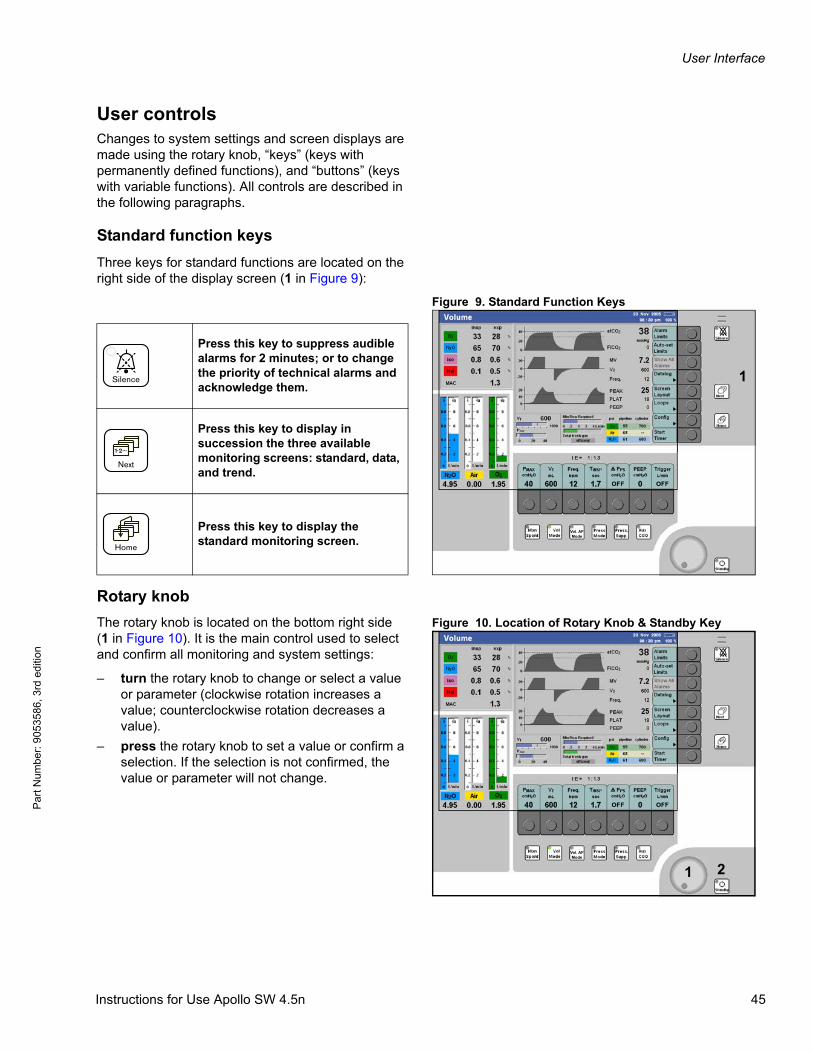
User Interface
Par
t Num
ber:
905
3586
, 3rd
edi
tion
User controlsChanges to system settings and screen displays are made using the rotary knob, “keys” (keys with permanently defined functions), and “buttons” (keys with variable functions). All controls are described in the following paragraphs.
Standard function keys
Three keys for standard functions are located on the right side of the display screen (1 in Figure 9):
Figure 9. Standard Function Keys
Rotary knob
Figure 10. Location of Rotary Knob & Standby KeyThe rotary knob is located on the bottom right side(1 in Figure 10). It is the main control used to select and confirm all monitoring and system settings:
– turn the rotary knob to change or select a value or parameter (clockwise rotation increases a value; counterclockwise rotation decreases a value).
– press the rotary knob to set a value or confirm a selection. If the selection is not confirmed, the value or parameter will not change.
Vol. AFMode
1
Press this key to suppress audible alarms for 2 minutes; or to change the priority of technical alarms and acknowledge them.
Press this key to display in succession the three available monitoring screens: standard, data, and trend.
Press this key to display the standard monitoring screen.
Vol. AFMode
1 2
Instructions for Use Apollo SW 4.5n 45
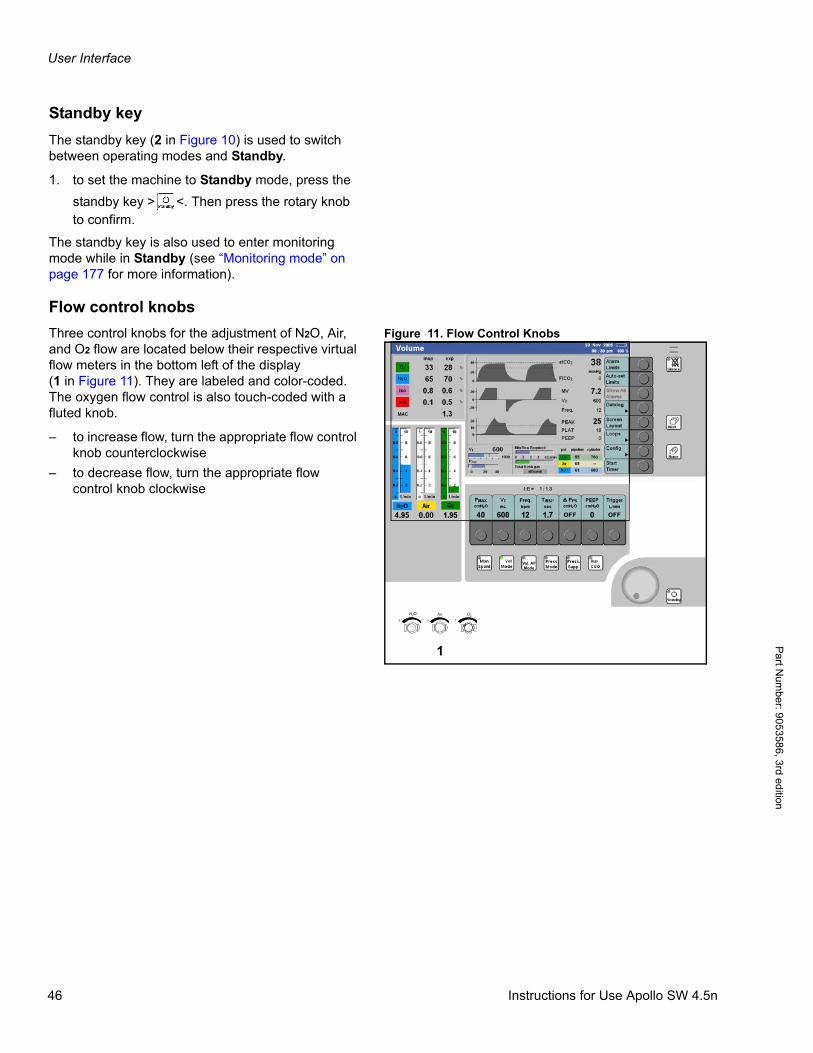
User Interface
Pa
rt Num
ber: 905358
6, 3rd edition
Standby key
The standby key (2 in Figure 10) is used to switch between operating modes and Standby.
1. to set the machine to Standby mode, press the
standby key > <. Then press the rotary knob to confirm.
The standby key is also used to enter monitoring mode while in Standby (see “Monitoring mode” on page 177 for more information).
Flow control knobs
Figure 11. Flow Control KnobsThree control knobs for the adjustment of N2O, Air, and O2 flow are located below their respective virtual flow meters in the bottom left of the display(1 in Figure 11). They are labeled and color-coded. The oxygen flow control is also touch-coded with a fluted knob.
– to increase flow, turn the appropriate flow control knob counterclockwise
– to decrease flow, turn the appropriate flow control knob clockwise
N 2 O Air O 2+ + +_ _ _
1
Vol. AFMode
46 Instructions for Use Apollo SW 4.5n

User Interface
Par
t Num
ber:
905
3586
, 3rd
edi
tion
Ventilation control keys
Figure 12. Location of Ventilation Control KeysVentilation functions are controlled using two sets of keys located at the bottom of the screen.
The ventilation keys (1 in Figure 12) are used primarily to select the ventilation mode:>Man Spont<, >Vol Mode<, >Vol. AF Mode<,>Press Mode<, and >Press. Supp.< (optional).The key >Aux CGO< is used to select the optional auxiliary common gas outlet.
Selecting Ventilation Mode or Aux CGO (optional)
1. Press the appropriate ventilation key. The key’s LED and the status field will flash.
2. Press the rotary knob to confirm the selection.
The ventilation buttons (2 in Figure 12), located above the keys, are used to set ventilation parameters. These keys have variable functions, depending on the operating status or ventilation mode.
Setting/Selecting Ventilation Parameters
Example: setting PEEP
1. Press the button >PEEP<.
2. Turn the rotary knob until the desired value is displayed.
3. Press the rotary knob to confirm the new value. If the new value is not confirmed within 15 seconds, it automatically reverts to the original value.
Vol. AFMode
1
2
Instructions for Use Apollo SW 4.5n 47
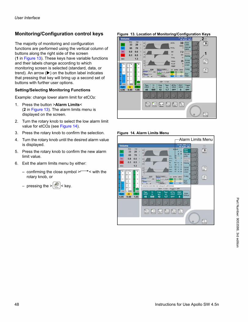
User Interface
Pa
rt Num
ber: 905358
6, 3rd edition
Figure 13. Location of Monitoring/Configuration KeysMonitoring/Configuration control keys
The majority of monitoring and configuration functions are performed using the vertical column of buttons along the right side of the screen(1 in Figure 13). These keys have variable functions and their labels change according to which monitoring screen is selected (standard, data, or trend). An arrow () on the button label indicates that pressing that key will bring up a second set of buttons with further user options.
Setting/Selecting Monitoring Functions
Example: change lower alarm limit for etCO2:
1. Press the button >Alarm Limits<(2 in Figure 13). The alarm limits menu is displayed on the screen.
2. Turn the rotary knob to select the low alarm limit value for etCO2 (see Figure 14).
Figure 14. Alarm Limits Menu3. Press the rotary knob to confirm the selection.
4. Turn the rotary knob until the desired alarm value is displayed.
5. Press the rotary knob to confirm the new alarm limit value.
6. Exit the alarm limits menu by either:
– confirming the close symbol > < with the rotary knob, or
– pressing the > < key.
Vol. AFMode
2
1
Vol. AFMode
Alarm Limits Menu
48 Instructions for Use Apollo SW 4.5n
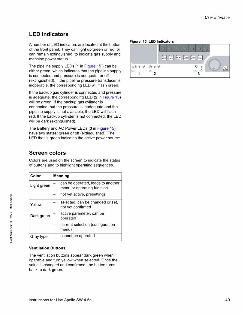
User Interface
Par
t Num
ber:
905
3586
, 3rd
edi
tion
LED indicatorsFigure 15. LED Indicators
A number of LED indicators are located at the bottom of the front panel. They can light up green or red, or can remain extinguished, to indicate gas supply and machine power status.
The pipeline supply LEDs (1 in Figure 15 ) can be either green, which indicates that the pipeline supply is connected and pressure is adequate, or off (extinguished). If the pipeline pressure transducer is inoperable, the corresponding LED will flash green.
If the backup gas cylinder is connected and pressure is adequate, the corresponding LED (2 in Figure 15) will be green. If the backup gas cylinder is connected, but the pressure is inadequate and the pipeline supply is not available, the LED will flash red. If the backup cylinder is not connected, the LED will be dark (extinguished).
The Battery and AC Power LEDs (3 in Figure 15) have two states: green or off (extinguished). The LED that is green indicates the active power source.
Screen colorsColors are used on the screen to indicate the status of buttons and to highlight operating sequences.
Ventilation Buttons
The ventilation buttons appear dark green when operable and turn yellow when selected. Once the value is changed and confirmed, the button turns back to dark green.
Vol. AFMode
1 32
Color Meaning
Light green– can be operated, leads to another
menu or operating function
– not yet active, presettings
Yellow– selected, can be changed or set,
not yet confirmed
Dark green– active parameter, can be
operated
– current selection (configuration menu)
Gray type – cannot be operated
Instructions for Use Apollo SW 4.5n 49
User Interface
Pa
rt Num
ber: 905358
6, 3rd edition
Some values change automatically when another parameter button is selected, and those values will be displayed in yellow in addition to the selected parameter.
Values shown in gray indicate that:
– there is a discrepancy between set and actual values, or
– specified accuracy is not being maintained.
Monitoring/Configuration Buttons
The monitoring buttons along the right side of the screen appear light green when operable. When selected, their color changes to dark green. They also change to dark green when another submenu or function is displayed.
Colors of Parameter Settings/Values in Menus
When the user selects a menu the parameters and values will appear on a dark green background. Currently selected submenus are framed in an orange border. Parameters in gray type are inactive and cannot be selected.
50 Instructions for Use Apollo SW 4.5n

User Interface
Par
t Num
ber:
905
3586
, 3rd
edi
tion
Menu structure overviewThis table provides an overview of allocations for the variable, vertical monitoring and configuration soft keys. Allocations vary depending on the operating mode and device configuration. The operating modes are contained in the headers; the soft keys are listed below these headers. Where other soft keys are available or the text on/function of a soft key changes after a particular soft key is pressed, information is contained in a separate column to the right of the soft key.
Check List
Absorb. changed
Undo Change
Start Self Test
Accept
Cancel Test
Cancel Test
Standby
Alarm Limits
Self Test Results
Absorb. changed
Leak Test
Datalog
Page 1
Page 2
Delete Trend
Cancel delete
Delete
Instructions for Use Apollo SW 4.5n 51
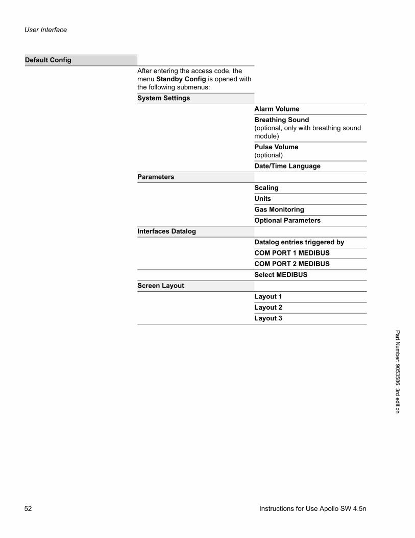
User Interface
Pa
rt Num
ber: 905358
6, 3rd edition
Default Config
After entering the access code, the menu Standby Config is opened with the following submenus:
System Settings
Alarm Volume
Breathing Sound (optional, only with breathing sound module)
Pulse Volume(optional)
Date/Time Language
Parameters
Scaling
Units
Gas Monitoring
Optional Parameters
Interfaces Datalog
Datalog entries triggered by
COM PORT 1 MEDIBUS
COM PORT 2 MEDIBUS
Select MEDIBUS
Screen Layout
Layout 1
Layout 2
Layout 3
52 Instructions for Use Apollo SW 4.5n

User Interface
Par
t Num
ber:
905
3586
, 3rd
edi
tion
Alarm Limits
Alarm Limits
Default Alarm Limits
Default Agent Limits
Alarms in Man/Spont.
Misc. alarm settings
Therapy related
Device related
Other
Ventilator and gas supply
Ventilator and gas supply
Parameter Default Values
Gas supply checks
Ventilator Default Settings
Weight related settings
Body Weight Related Ventilator Settings
System Info
General Information
Activate Option
Trace 1
Trace 2
Trace 3
Remote Service
Monitor Mode
Instructions for Use Apollo SW 4.5n 53
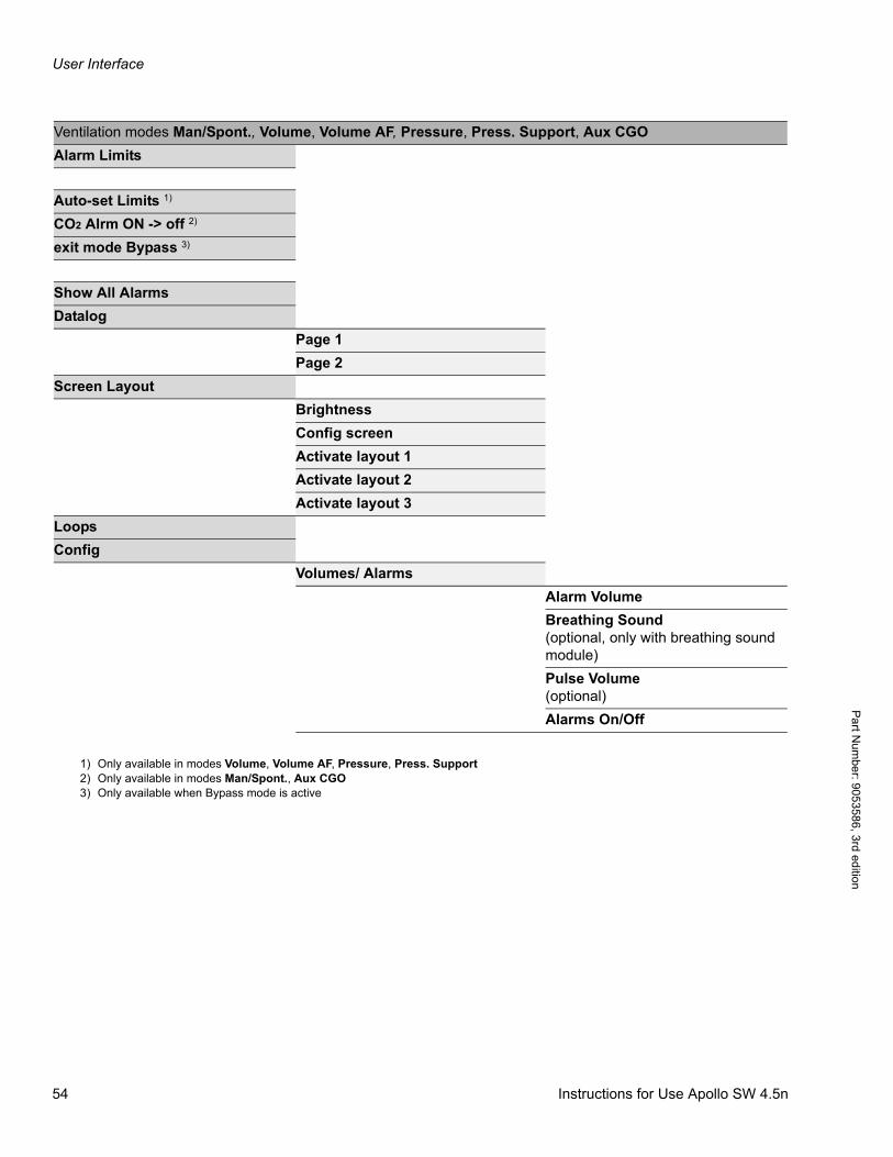
User Interface
Pa
rt Num
ber: 905358
6, 3rd edition
Ventilation modes Man/Spont., Volume, Volume AF, Pressure, Press. Support, Aux CGO
Alarm Limits
Auto-set Limits 1)
CO2 Alrm ON -> off 2)
exit mode Bypass 3)
Show All Alarms
Datalog
Page 1
Page 2
Screen Layout
Brightness
Config screen
Activate layout 1
Activate layout 2
Activate layout 3
Loops
Config
Volumes/ Alarms
Alarm Volume
Breathing Sound(optional, only with breathing sound module)
Pulse Volume(optional)
Alarms On/Off
1) Only available in modes Volume, Volume AF, Pressure, Press. Support2) Only available in modes Man/Spont., Aux CGO3) Only available when Bypass mode is active
54 Instructions for Use Apollo SW 4.5n
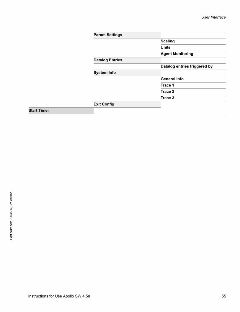
User Interface
Par
t Num
ber:
905
3586
, 3rd
edi
tion
Param Settings
Scaling
Units
Agent Monitoring
Datalog Entries
Datalog entries triggered by
System Info
General Info
Trace 1
Trace 2
Trace 3
Exit Config
Start Timer
Instructions for Use Apollo SW 4.5n 55

User Interface
Pa
rt Num
ber: 905358
6, 3rd edition
This page intentionally left blank.
56 Instructions for Use Apollo SW 4.5n
System Setup
Par
t Num
ber:
905
3586
, 3rd
edi
tion
System Setup
ContentsOverview . . . . . . . . . . . . . . . . . . . . . . . . . . . . . . . . . . . . . . . . . . . . . . . . . . . . . . . . . . . . . . . . . . . . . . . . . . . . . . . 59
Preparation before first use . . . . . . . . . . . . . . . . . . . . . . . . . . . . . . . . . . . . . . . . . . . . . . . . . . . . . . . . . . . . . . . . 59
Charging the battery for emergency operation . . . . . . . . . . . . . . . . . . . . . . . . . . . . . . . . . . . . . . . . . . . . . . . . 59
Installing the breathing system and flow sensors . . . . . . . . . . . . . . . . . . . . . . . . . . . . . . . . . . . . . . . . . . . . . 61
Filling and installing the absorber . . . . . . . . . . . . . . . . . . . . . . . . . . . . . . . . . . . . . . . . . . . . . . . . . . . . . . . . . . 63
Reusable absorber . . . . . . . . . . . . . . . . . . . . . . . . . . . . . . . . . . . . . . . . . . . . . . . . . . . . . . . . . . . . . . . . . . . . . . . . 63
Disposable CLIC absorber (optional) . . . . . . . . . . . . . . . . . . . . . . . . . . . . . . . . . . . . . . . . . . . . . . . . . . . . . . . . . . 64
Connecting the gas supply . . . . . . . . . . . . . . . . . . . . . . . . . . . . . . . . . . . . . . . . . . . . . . . . . . . . . . . . . . . . . . . . 65
Connecting pipeline supply of N2O, Air, and O2 . . . . . . . . . . . . . . . . . . . . . . . . . . . . . . . . . . . . . . . . . . . . . . . . . 66
Connecting the backup gas cylinders . . . . . . . . . . . . . . . . . . . . . . . . . . . . . . . . . . . . . . . . . . . . . . . . . . . . . . . . . . 68
Caution when handling O2 cylinders . . . . . . . . . . . . . . . . . . . . . . . . . . . . . . . . . . . . . . . . . . . . . . . . . . . . . . . . . . 70
Connecting the scavenger system . . . . . . . . . . . . . . . . . . . . . . . . . . . . . . . . . . . . . . . . . . . . . . . . . . . . . . . . . . 71
Connecting the anesthetic gas receiving system AGS (Optional) . . . . . . . . . . . . . . . . . . . . . . . . . . . . . . . . . . . . 71
Connecting the passive scavenger system (Optional) . . . . . . . . . . . . . . . . . . . . . . . . . . . . . . . . . . . . . . . . . . . . . 73
Connecting the endotracheal aspiration system (Optional) . . . . . . . . . . . . . . . . . . . . . . . . . . . . . . . . . . . . . 74
Installing vaporizers . . . . . . . . . . . . . . . . . . . . . . . . . . . . . . . . . . . . . . . . . . . . . . . . . . . . . . . . . . . . . . . . . . . . . . 74
Installing the flexible arm for the breathing bag . . . . . . . . . . . . . . . . . . . . . . . . . . . . . . . . . . . . . . . . . . . . . . . 75
Connecting the patient system . . . . . . . . . . . . . . . . . . . . . . . . . . . . . . . . . . . . . . . . . . . . . . . . . . . . . . . . . . . . . 76
Connecting the patient circuit . . . . . . . . . . . . . . . . . . . . . . . . . . . . . . . . . . . . . . . . . . . . . . . . . . . . . . . . . . . . . . . . 77
Table with recommended hose configurations . . . . . . . . . . . . . . . . . . . . . . . . . . . . . . . . . . . . . . . . . . . . . . . . . . . 80
Connecting AC power . . . . . . . . . . . . . . . . . . . . . . . . . . . . . . . . . . . . . . . . . . . . . . . . . . . . . . . . . . . . . . . . . . . . 84
Connecting auxiliary devices . . . . . . . . . . . . . . . . . . . . . . . . . . . . . . . . . . . . . . . . . . . . . . . . . . . . . . . . . . . . . . . . 84
Fuses for auxiliary outlets . . . . . . . . . . . . . . . . . . . . . . . . . . . . . . . . . . . . . . . . . . . . . . . . . . . . . . . . . . . . . . . . . . . 85
Establishing potential equalization . . . . . . . . . . . . . . . . . . . . . . . . . . . . . . . . . . . . . . . . . . . . . . . . . . . . . . . . . . . . 85
Connecting the power supply . . . . . . . . . . . . . . . . . . . . . . . . . . . . . . . . . . . . . . . . . . . . . . . . . . . . . . . . . . . . . . . . 86
Information about transport within the clinic . . . . . . . . . . . . . . . . . . . . . . . . . . . . . . . . . . . . . . . . . . . . . . . . . 86
Instructions for Use Apollo SW 4.5n 57

System Setup
Pa
rt Num
ber: 905358
6, 3rd edition
This page intentionally left blank.
58 Instructions for Use Apollo SW 4.5n
System Setup
Par
t Num
ber:
905
3586
, 3rd
edi
tion
OverviewThis chapter provides information on how to set up and install all system components needed to prepare the Apollo for use. The setup procedure shall be followed by the performance of the periodic manufacturer’s procedure.
Preparation before first useBefore first use, Apollo must be prepared in accordance with the information in the chapter “Cleaning and Disinfection Guidelines” on page 235.
Charging the battery for emer-gency operationApollo has a built-in uninterruptible power supply UPS which maintains the power supply for at least 30 minutes (up to 90 minutes, depending on the ventilation parameters) in the event of a mains power failure, provided that the battery is fully charged.
Switching to battery power (UPS) takes place automatically and is indicated on the screen by the message: POWER FAIL.
The battery recharges automatically when the anesthesia machine is plugged into the mains, but only up to a maximum ambient temperature of 95° F/35° C.
WARNING!
Risk of patient injury
Correct preparation of the anesthesia machine is required to minimize the general risks associated with the anesthesia machine.
Use only clean and disinfected parts and always strictly follow the cleaning and assembly instructions contained in these Instructions for Use to prevent infection of patient or user.
Instructions for Use Apollo SW 4.5n 59
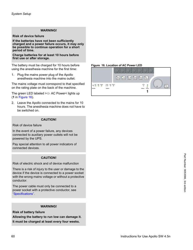
System Setup
Pa
rt Num
ber: 905358
6, 3rd edition
Figure 16. Location of AC Power LEDThe battery must be charged for 10 hours before using the anesthesia machine for the first time:
1. Plug the mains power plug of the Apollo anesthesia machine into the mains outlet.
The mains voltage must correspond to that specified on the rating plate on the back of the machine.
The green LED labeled >N AC Power< lights up(1 in Figure 16).
2. Leave the Apollo connected to the mains for 10 hours. The anesthesia machine does not have to be switched on.
WARNING!
Risk of device failure
If the batteries have not been sufficiently charged and a power failure occurs, it may only be possible to continue operation for a short period of time.
Charge batteries for at least 10 hours before first use or after storage.
1
Vol. AFMode
CAUTION!
Risk of device failure
In the event of a power failure, any devices connected to auxiliary power outlets will not be powered by the UPS.
Pay special attention to all power indicators of connected devices.
CAUTION!
Risk of electric shock and of device malfunction
There is a risk of injury to the user or damage to the device if the device is connected to a power socket with the wrong mains voltage or without a protective conductor.
The power cable must only be connected to a power socket with a protective conductor, see “Specifications”.
WARNING!
Risk of battery failure
Allowing the battery to run low can damage it.
It must be charged at least every four weeks.
60 Instructions for Use Apollo SW 4.5n
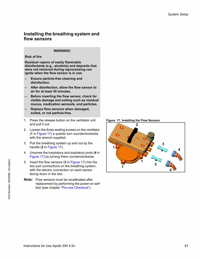
System Setup
Par
t Num
ber:
905
3586
, 3rd
edi
tion
Installing the breathing system and flow sensors
Figure 17. Installing the Flow Sensors1. Press the release button on the ventilator unit and pull it out.
2. Loosen the three sealing screws on the ventilator (1 in Figure 17) a quarter turn counterclockwise with the wrench supplied.
3. Pull the breathing system up and out by the handle (2 in Figure 17).
4. Unscrew the inspiratory and expiratory ports (4 in Figure 17) by turning them counterclockwise.
5. Insert the flow sensors (3 in Figure 17) into the two port connections on the breathing system, with the electric connection on each sensor facing down in the slot.
Note: Flow sensors must be recalibrated after replacement by performing the power-on self test (see chapter “Pre-use Checkout”).
WARNING!
Risk of fire
Residual vapors of easily flammable disinfectants (e.g., alcohols) and deposits that were not removed during reprocessing can ignite when the flow sensor is in use.
– Ensure particle-free cleaning and disinfection.
– After disinfection, allow the flow sensor to air for at least 30 minutes.
– Before inserting the flow sensor, check for visible damage and soiling such as residual mucus, medication aerosols, and particles.
– Replace flow sensors when damaged, soiled, or not particle-free.
3
3
4
41
1
1
2
Instructions for Use Apollo SW 4.5n 61
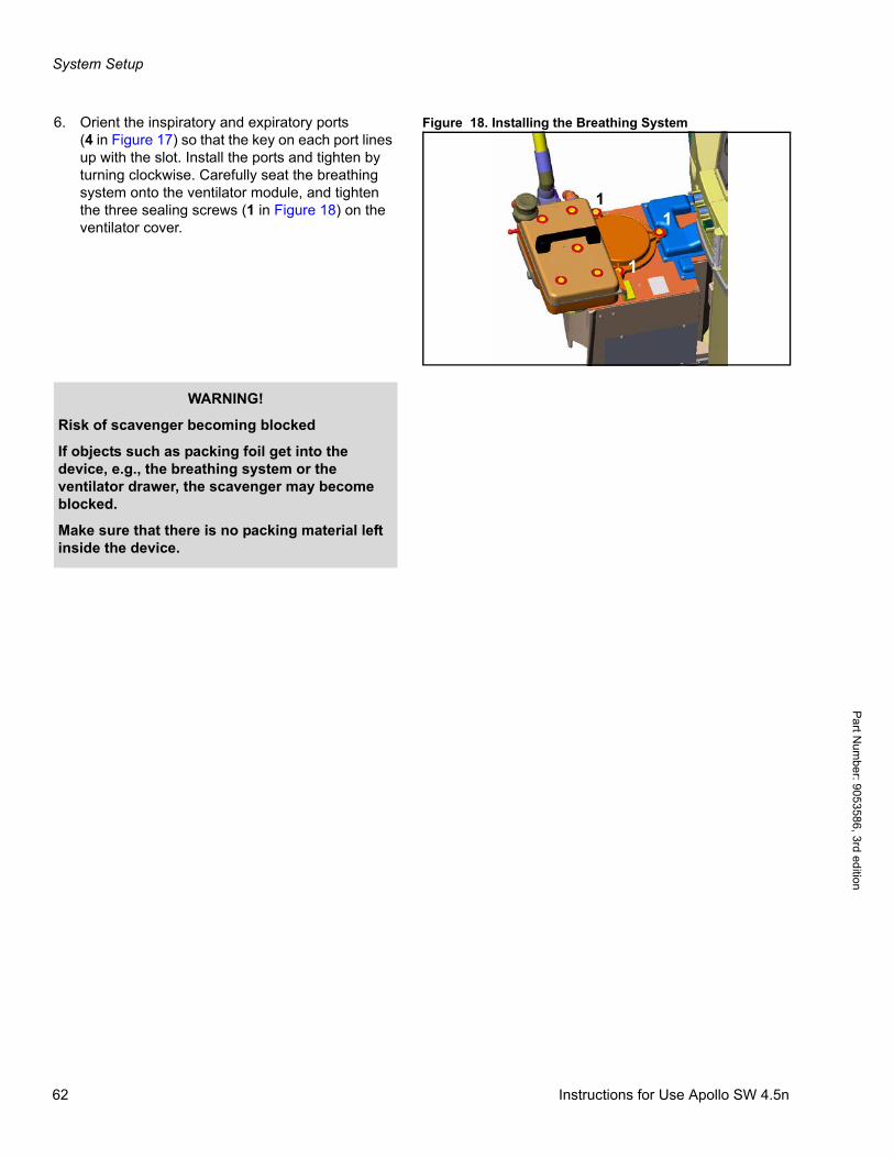
System Setup
Pa
rt Num
ber: 905358
6, 3rd edition
Figure 18. Installing the Breathing System6. Orient the inspiratory and expiratory ports(4 in Figure 17) so that the key on each port lines up with the slot. Install the ports and tighten by turning clockwise. Carefully seat the breathing system onto the ventilator module, and tighten the three sealing screws (1 in Figure 18) on the ventilator cover.
11
1
WARNING!
Risk of scavenger becoming blocked
If objects such as packing foil get into the device, e.g., the breathing system or the ventilator drawer, the scavenger may become blocked.
Make sure that there is no packing material left inside the device.
62 Instructions for Use Apollo SW 4.5n

System Setup
Par
t Num
ber:
905
3586
, 3rd
edi
tion
Filling and installing the absorberA reusable absorber or the disposable CLIC absorber can be used.
Reusable absorber
Figure 19. Installing the Absorber Canister1. Push the insert fully into the absorber canister(1 in Figure 19).
2. Fill the absorber canister with fresh soda lime up to the MAX mark.
3. Fit the canister into position below the breathing system, and turn counterclockwise as far as possible (2 in Figure 19).
4. Slowly push in the ventilator module until it engages.
5. Reset the soda lime change log to current date by pressing the >soda lime changed< button, see page 97.
If the breathing system is not to be used within the next 24 hours:
– Only fill with soda lime immediately before use.
21
WARNING!
Risk of injury
Absorbent is caustic and is a strong eye, skin, and respiratory tract irritant.
Use care when handling the absorbent to avoid spills.
CAUTION!
Risk of device failure
It is recommended that Drägersorb 800 + or Drägersorb FREE are used.
Do not use powdered soda lime, as a higher dust load may impair functionality of the Apollo anesthesia machine.
Instructions for Use Apollo SW 4.5n 63
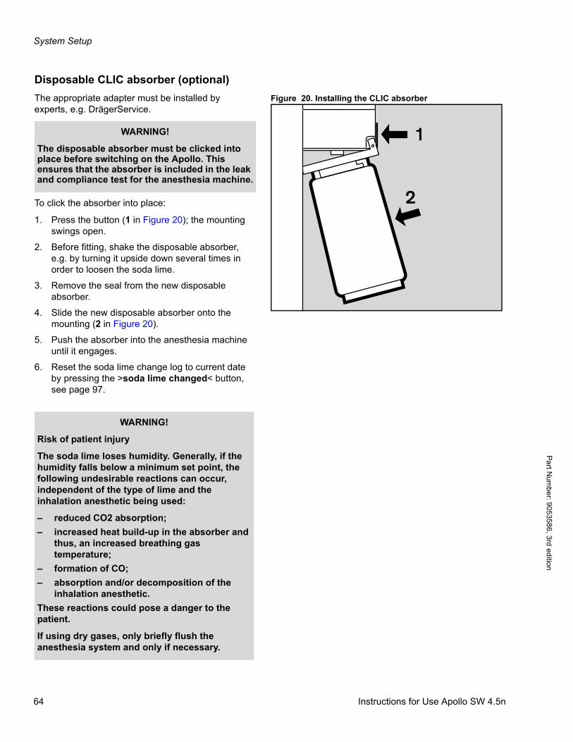
System Setup
Pa
rt Num
ber: 905358
6, 3rd edition
Disposable CLIC absorber (optional)
Figure 20. Installing the CLIC absorberThe appropriate adapter must be installed by experts, e.g. DrägerService.
To click the absorber into place:
1. Press the button (1 in Figure 20); the mounting swings open.
2. Before fitting, shake the disposable absorber, e.g. by turning it upside down several times in order to loosen the soda lime.
3. Remove the seal from the new disposable absorber.
4. Slide the new disposable absorber onto the mounting (2 in Figure 20).
5. Push the absorber into the anesthesia machine until it engages.
6. Reset the soda lime change log to current date by pressing the >soda lime changed< button, see page 97.
1
2
WARNING!
The disposable absorber must be clicked into place before switching on the Apollo. This ensures that the absorber is included in the leak and compliance test for the anesthesia machine.
WARNING!
Risk of patient injury
The soda lime loses humidity. Generally, if the humidity falls below a minimum set point, the following undesirable reactions can occur, independent of the type of lime and the inhalation anesthetic being used:
– reduced CO2 absorption;
– increased heat build-up in the absorber and thus, an increased breathing gas temperature;
– formation of CO;
– absorption and/or decomposition of the inhalation anesthetic.
These reactions could pose a danger to the patient.
If using dry gases, only briefly flush the anesthesia system and only if necessary.
64 Instructions for Use Apollo SW 4.5n
System Setup
Par
t Num
ber:
905
3586
, 3rd
edi
tion
Connecting the gas supply
WARNING!
Risk of explosion, fire
Oil and grease may combine explosively with oxygen or nitrous oxide. For this reason, oil and grease must never come in contact with pipelines, cylinders, cylinder valves, gauges, fittings, etc., which conduct oxygen or nitrous oxide within the machine.
CAUTION!
Risk of gas supply failure
If all gas supplies (pipeline or cylinder) are not connected correctly, the reserve system will not be available in the event of a gas supply failure.
Make sure that all supplies are connected according to the engraving on the gas supply block and the illustrations at the back of the machine. After connecting the supplies, ensure proper functionality.
CAUTION!
Risk of device failure
Compressed gas supply (pipeline or cylinder): To avoid damaging the device(s) attached to a gas supply, use only medical gases. Pay particular attention to national and international standards regulating the use of medical gases.
Instructions for Use Apollo SW 4.5n 65
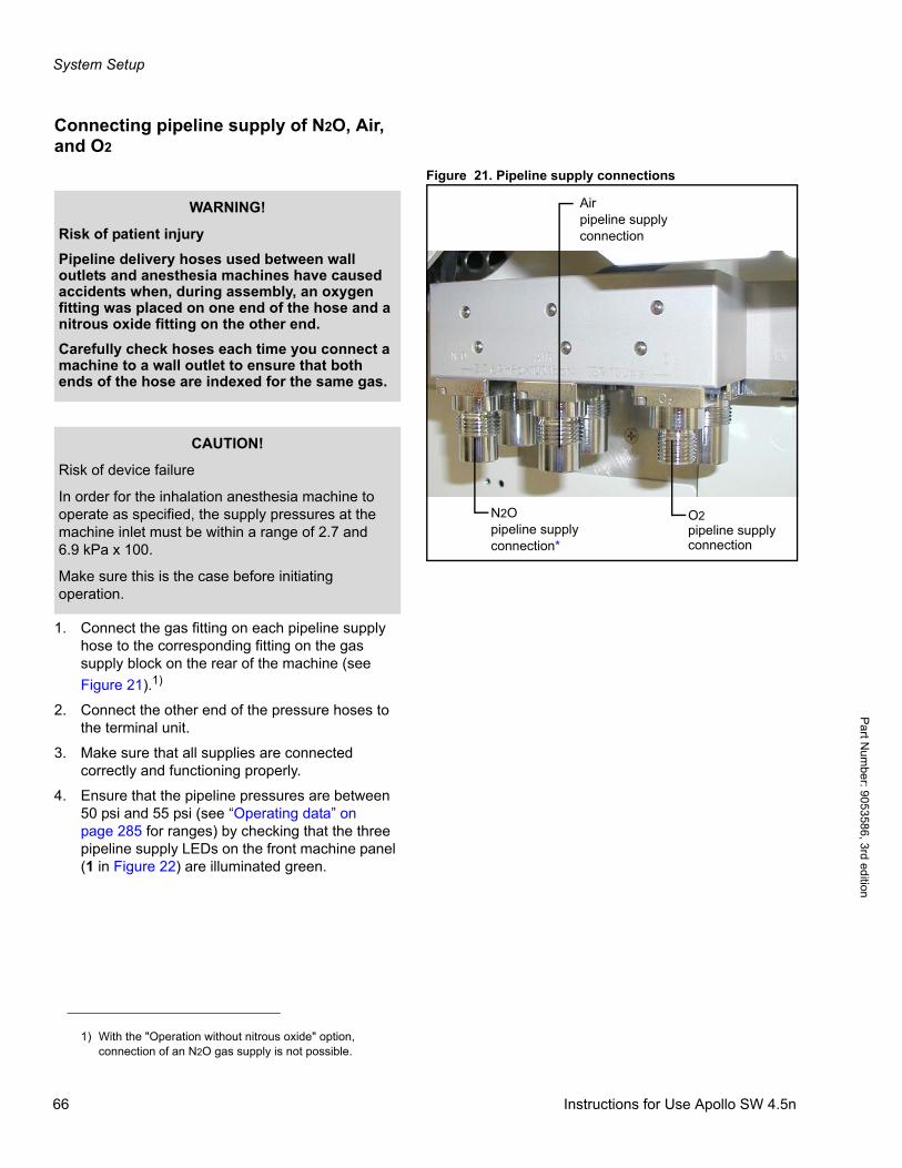
System Setup
Pa
rt Num
ber: 905358
6, 3rd edition
Connecting pipeline supply of N2O, Air, and O2
Figure 21. Pipeline supply connections
1. Connect the gas fitting on each pipeline supply hose to the corresponding fitting on the gas supply block on the rear of the machine (see
Figure 21).1)
2. Connect the other end of the pressure hoses to the terminal unit.
3. Make sure that all supplies are connected correctly and functioning properly.
4. Ensure that the pipeline pressures are between 50 psi and 55 psi (see “Operating data” on page 285 for ranges) by checking that the three pipeline supply LEDs on the front machine panel (1 in Figure 22) are illuminated green.
N2Opipeline supplyconnection*
O2pipeline supplyconnection
Airpipeline supplyconnection
WARNING!
Risk of patient injury
Pipeline delivery hoses used between wall outlets and anesthesia machines have caused accidents when, during assembly, an oxygen fitting was placed on one end of the hose and a nitrous oxide fitting on the other end.
Carefully check hoses each time you connect a machine to a wall outlet to ensure that both ends of the hose are indexed for the same gas.
CAUTION!
Risk of device failure
In order for the inhalation anesthesia machine to operate as specified, the supply pressures at the machine inlet must be within a range of 2.7 and 6.9 kPa x 100.
Make sure this is the case before initiating operation.
1) With the "Operation without nitrous oxide" option, connection of an N2O gas supply is not possible.
66 Instructions for Use Apollo SW 4.5n
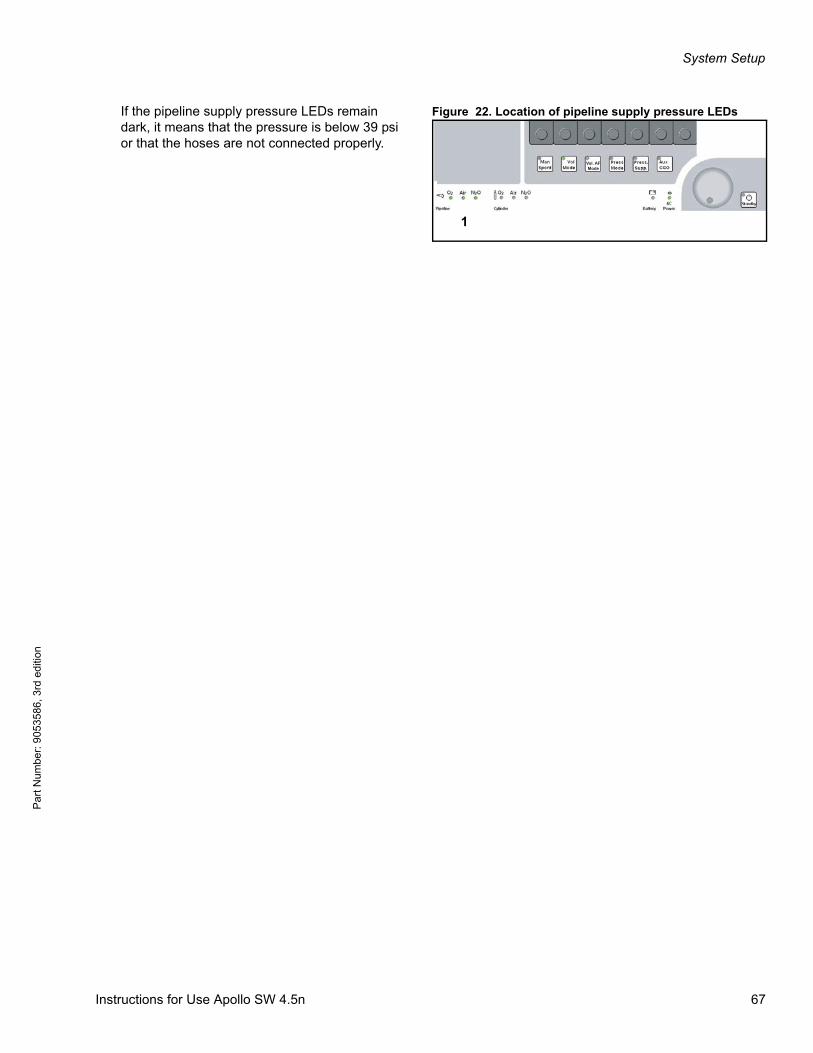
System Setup
Par
t Num
ber:
905
3586
, 3rd
edi
tion
Figure 22. Location of pipeline supply pressure LEDsIf the pipeline supply pressure LEDs remain dark, it means that the pressure is below 39 psi or that the hoses are not connected properly.
1
Vol. AFMode
Instructions for Use Apollo SW 4.5n 67
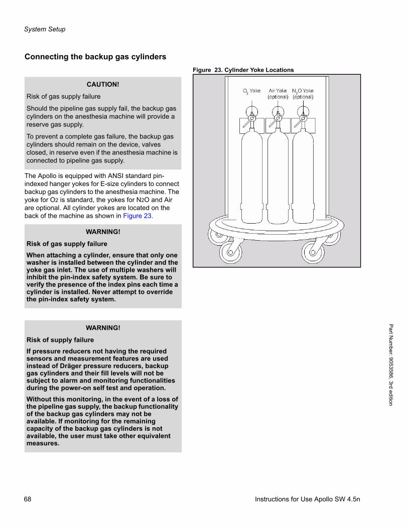
System Setup
Pa
rt Num
ber: 905358
6, 3rd edition
Connecting the backup gas cylinders
Figure 23. Cylinder Yoke Locations
The Apollo is equipped with ANSI standard pin-indexed hanger yokes for E-size cylinders to connect backup gas cylinders to the anesthesia machine. The yoke for O2 is standard, the yokes for N2O and Air are optional. All cylinder yokes are located on the back of the machine as shown in Figure 23.
CAUTION!
Risk of gas supply failure
Should the pipeline gas supply fail, the backup gas cylinders on the anesthesia machine will provide a reserve gas supply.
To prevent a complete gas failure, the backup gas cylinders should remain on the device, valves closed, in reserve even if the anesthesia machine is connected to pipeline gas supply.
WARNING!
Risk of gas supply failure
When attaching a cylinder, ensure that only one washer is installed between the cylinder and the yoke gas inlet. The use of multiple washers will inhibit the pin-index safety system. Be sure to verify the presence of the index pins each time a cylinder is installed. Never attempt to override the pin-index safety system.
WARNING!
Risk of supply failure
If pressure reducers not having the required sensors and measurement features are used instead of Dräger pressure reducers, backup gas cylinders and their fill levels will not be subject to alarm and monitoring functionalities during the power-on self test and operation.
Without this monitoring, in the event of a loss of the pipeline gas supply, the backup functionality of the backup gas cylinders may not be available. If monitoring for the remaining capacity of the backup gas cylinders is not available, the user must take other equivalent measures.
68 Instructions for Use Apollo SW 4.5n
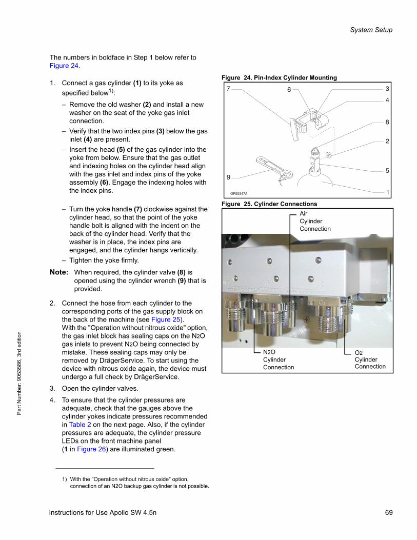
System Setup
Par
t Num
ber:
905
3586
, 3rd
edi
tion
The numbers in boldface in Step 1 below refer to Figure 24.
Figure 24. Pin-Index Cylinder Mounting1. Connect a gas cylinder (1) to its yoke as
specified below1):
– Remove the old washer (2) and install a new washer on the seat of the yoke gas inlet connection.
– Verify that the two index pins (3) below the gas inlet (4) are present.
– Insert the head (5) of the gas cylinder into the yoke from below. Ensure that the gas outlet and indexing holes on the cylinder head align with the gas inlet and index pins of the yoke assembly (6). Engage the indexing holes with the index pins.
Figure 25. Cylinder Connections– Turn the yoke handle (7) clockwise against the
cylinder head, so that the point of the yoke handle bolt is aligned with the indent on the back of the cylinder head. Verify that the washer is in place, the index pins are engaged, and the cylinder hangs vertically.
– Tighten the yoke firmly.
Note: When required, the cylinder valve (8) is opened using the cylinder wrench (9) that is provided.
2. Connect the hose from each cylinder to the corresponding ports of the gas supply block on the back of the machine (see Figure 25).With the "Operation without nitrous oxide" option, the gas inlet block has sealing caps on the N2O gas inlets to prevent N2O being connected by mistake. These sealing caps may only be removed by DrägerService. To start using the device with nitrous oxide again, the device must undergo a full check by DrägerService.
3. Open the cylinder valves.
4. To ensure that the cylinder pressures are adequate, check that the gauges above the cylinder yokes indicate pressures recommended in Table 2 on the next page. Also, if the cylinder pressures are adequate, the cylinder pressure LEDs on the front machine panel(1 in Figure 26) are illuminated green.
OP00347A
67
9
3
4
8
2
5
1
1) With the "Operation without nitrous oxide" option, connection of an N2O backup gas cylinder is not possible.
N2OCylinderConnection
O2CylinderConnection
AirCylinderConnection
Instructions for Use Apollo SW 4.5n 69
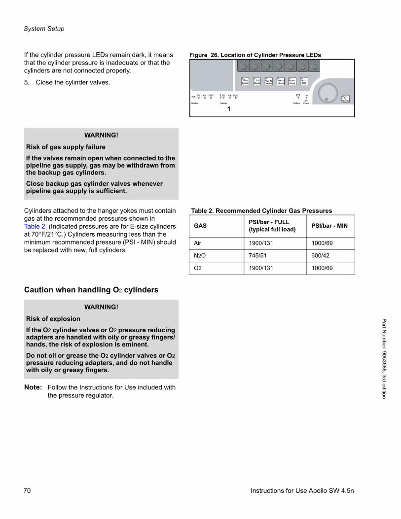
System Setup
Pa
rt Num
ber: 905358
6, 3rd edition
Figure 26. Location of Cylinder Pressure LEDsIf the cylinder pressure LEDs remain dark, it means that the cylinder pressure is inadequate or that the cylinders are not connected properly.
5. Close the cylinder valves.
Table 2. Recommended Cylinder Gas PressuresCylinders attached to the hanger yokes must contain gas at the recommended pressures shown inTable 2. (Indicated pressures are for E-size cylinders at 70°F/21°C.) Cylinders measuring less than the minimum recommended pressure (PSI - MIN) should be replaced with new, full cylinders.
Caution when handling O2 cylinders
Note: Follow the Instructions for Use included with the pressure regulator.
1
Vol. AFMode
WARNING!
Risk of gas supply failure
If the valves remain open when connected to the pipeline gas supply, gas may be withdrawn from the backup gas cylinders.
Close backup gas cylinder valves whenever pipeline gas supply is sufficient.
GASPSI/bar - FULL(typical full load)
PSI/bar - MIN
Air 1900/131 1000/69
N2O 745/51 600/42
O2 1900/131 1000/69
WARNING!
Risk of explosion
If the O2 cylinder valves or O2 pressure reducing adapters are handled with oily or greasy fingers/ hands, the risk of explosion is eminent.
Do not oil or grease the O2 cylinder valves or O2 pressure reducing adapters, and do not handle with oily or greasy fingers.
70 Instructions for Use Apollo SW 4.5n
System Setup
Par
t Num
ber:
905
3586
, 3rd
edi
tion
Connecting the scavenger systemAccording to the particular requirements for anesthesia workstations, the use of an anesthetic gas scavenging system is required.
The Apollo can be equipped with one of two kinds of scavenger systems to provide the best match with the hospital’s waste-gas disposal system. These scavenger systems must comply with ISO 8835-3.
Connecting the anesthetic gas receiving system AGS (Optional)
The anesthetic gas receiving system AGS is used with vacuum waste-gas disposal systems.
CAUTION!
Risk of increased ambient gas concentration
Ambient air may become contaminated with anesthetic agent if the scavenger hoses are functionally inhibited.
The scavenger hoses must not be pinched, kinked, or blocked in any manner.
WARNING!
Risk of scavenger becoming blocked
If objects such as packing foil get into the device, e.g., the breathing system or the ventilator drawer, the scavenger may become blocked.
Make sure that there is no packing material left inside the device.
Instructions for Use Apollo SW 4.5n 71
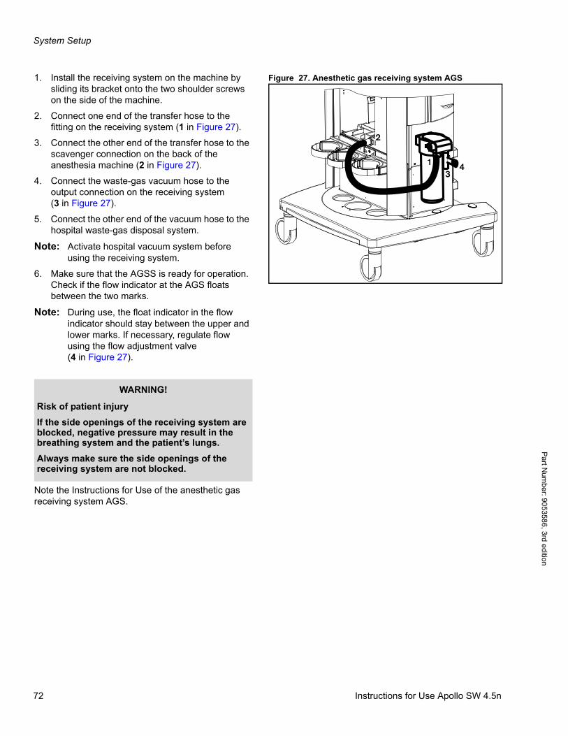
System Setup
Pa
rt Num
ber: 905358
6, 3rd edition
Figure 27. Anesthetic gas receiving system AGS1. Install the receiving system on the machine by sliding its bracket onto the two shoulder screws on the side of the machine.
2. Connect one end of the transfer hose to the fitting on the receiving system (1 in Figure 27).
3. Connect the other end of the transfer hose to the scavenger connection on the back of the anesthesia machine (2 in Figure 27).
4. Connect the waste-gas vacuum hose to the output connection on the receiving system(3 in Figure 27).
5. Connect the other end of the vacuum hose to the hospital waste-gas disposal system.
Note: Activate hospital vacuum system before using the receiving system.
6. Make sure that the AGSS is ready for operation. Check if the flow indicator at the AGS floats between the two marks.
Note: During use, the float indicator in the flow indicator should stay between the upper and lower marks. If necessary, regulate flow using the flow adjustment valve(4 in Figure 27).
Note the Instructions for Use of the anesthetic gas receiving system AGS.
13
4
2
WARNING!
Risk of patient injury
If the side openings of the receiving system are blocked, negative pressure may result in the breathing system and the patient’s lungs.
Always make sure the side openings of the receiving system are not blocked.
72 Instructions for Use Apollo SW 4.5n
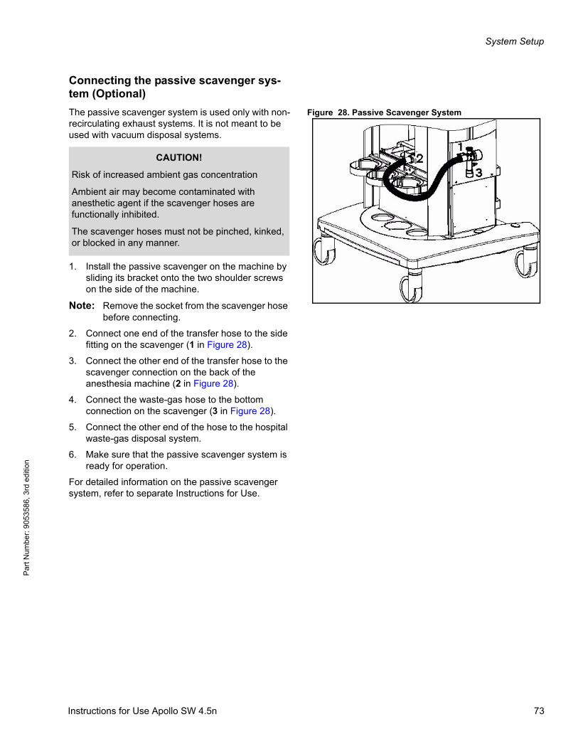
System Setup
Par
t Num
ber:
905
3586
, 3rd
edi
tion
Connecting the passive scavenger sys-tem (Optional)
Figure 28. Passive Scavenger SystemThe passive scavenger system is used only with non-recirculating exhaust systems. It is not meant to be used with vacuum disposal systems.
1. Install the passive scavenger on the machine by sliding its bracket onto the two shoulder screws on the side of the machine.
Note: Remove the socket from the scavenger hose before connecting.
2. Connect one end of the transfer hose to the side fitting on the scavenger (1 in Figure 28).
3. Connect the other end of the transfer hose to the scavenger connection on the back of the anesthesia machine (2 in Figure 28).
4. Connect the waste-gas hose to the bottom connection on the scavenger (3 in Figure 28).
5. Connect the other end of the hose to the hospital waste-gas disposal system.
6. Make sure that the passive scavenger system is ready for operation.
For detailed information on the passive scavenger system, refer to separate Instructions for Use.
CAUTION!
Risk of increased ambient gas concentration
Ambient air may become contaminated with anesthetic agent if the scavenger hoses are functionally inhibited.
The scavenger hoses must not be pinched, kinked, or blocked in any manner.
Instructions for Use Apollo SW 4.5n 73
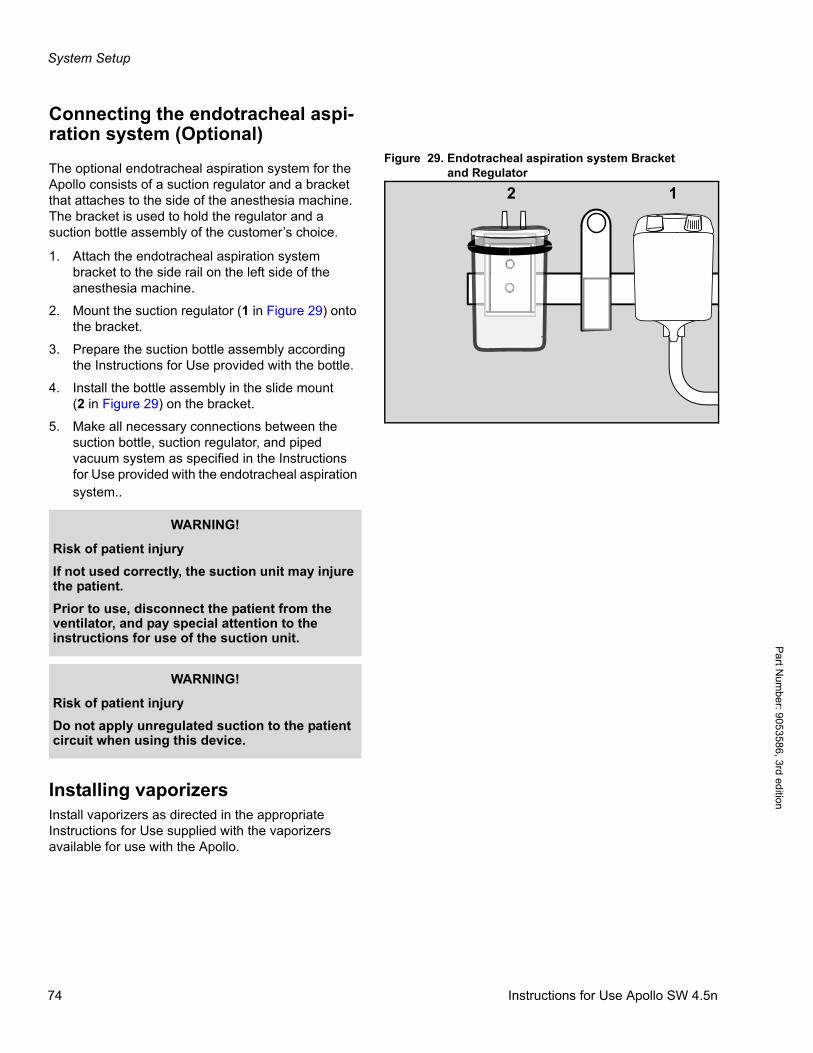
System Setup
Pa
rt Num
ber: 905358
6, 3rd edition
Connecting the endotracheal aspi-ration system (Optional)
Figure 29. Endotracheal aspiration system Bracketand RegulatorThe optional endotracheal aspiration system for the
Apollo consists of a suction regulator and a bracket that attaches to the side of the anesthesia machine. The bracket is used to hold the regulator and a suction bottle assembly of the customer’s choice.
1. Attach the endotracheal aspiration system bracket to the side rail on the left side of the anesthesia machine.
2. Mount the suction regulator (1 in Figure 29) onto the bracket.
3. Prepare the suction bottle assembly according the Instructions for Use provided with the bottle.
4. Install the bottle assembly in the slide mount(2 in Figure 29) on the bracket.
5. Make all necessary connections between the suction bottle, suction regulator, and piped vacuum system as specified in the Instructions for Use provided with the endotracheal aspiration system..
Installing vaporizersInstall vaporizers as directed in the appropriate Instructions for Use supplied with the vaporizers available for use with the Apollo.
12
WARNING!
Risk of patient injury
If not used correctly, the suction unit may injure the patient.
Prior to use, disconnect the patient from the ventilator, and pay special attention to the instructions for use of the suction unit.
WARNING!
Risk of patient injury
Do not apply unregulated suction to the patient circuit when using this device.
74 Instructions for Use Apollo SW 4.5n
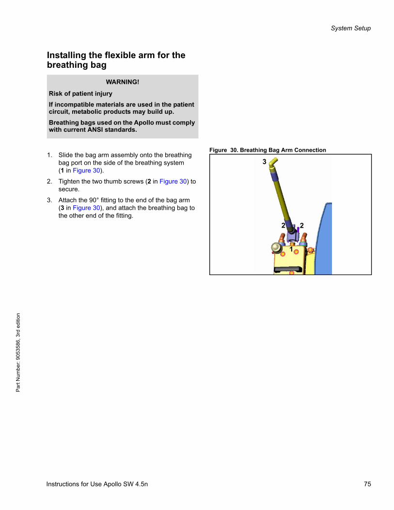
System Setup
Par
t Num
ber:
905
3586
, 3rd
edi
tion
Installing the flexible arm for the breathing bag
Figure 30. Breathing Bag Arm Connection1. Slide the bag arm assembly onto the breathing
bag port on the side of the breathing system(1 in Figure 30).
2. Tighten the two thumb screws (2 in Figure 30) to secure.
3. Attach the 90° fitting to the end of the bag arm(3 in Figure 30), and attach the breathing bag to the other end of the fitting.
WARNING!
Risk of patient injury
If incompatible materials are used in the patient circuit, metabolic products may build up.
Breathing bags used on the Apollo must comply with current ANSI standards.
1
22
3
Instructions for Use Apollo SW 4.5n 75
System Setup
Pa
rt Num
ber: 905358
6, 3rd edition
Connecting the patient system
Note: Apollo (without accessories) is not made with natural rubber latex. To minimize the risk of exposure to latex, use latex-free breathing bags and breathing hoses.
Note: Only use original sample line - other lines may change the technical data for the device.
Note: For sample lines available for use with the Apollo, see the list of accessories.
WARNING!
Risk of infection
Unpackaged or non-reprocessed components might be contaminated with pathogenic germs.
– To prevent cross-infection of patients or users, use only new or reprocessed components.
– Observe reprocessing instructions and assembly instructions.
WARNING!
Risk of burns
Conductive breathing hoses or face masks may cause burns during HF surgery.
Do not use these types of hoses and masks in combination with HF surgery.
WARNING!
Risk due to particles and dust
To protect the patient from particles and dust, a filter must be used between the inspiratory limb of the breathing system and the patient.
Use a Y-piece filter or filter on the inspiratory port.
CAUTION!
Risk of inadequate gas concentrations
If the patient system components are not tightly connected, ambient air will be added to the gas mixture.
Make sure that all patient system components are tightly connected.
76 Instructions for Use Apollo SW 4.5n
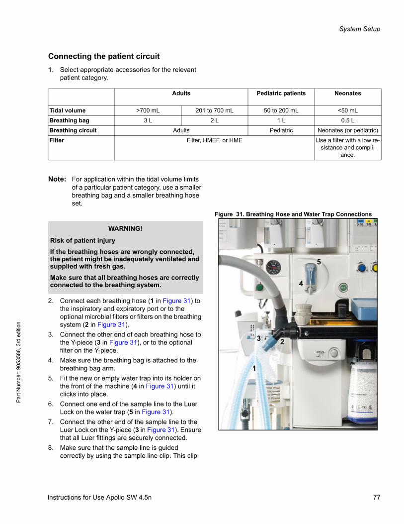
System Setup
Par
t Num
ber:
905
3586
, 3rd
edi
tion
Connecting the patient circuit
1. Select appropriate accessories for the relevant patient category.
Note: For application within the tidal volume limits of a particular patient category, use a smaller breathing bag and a smaller breathing hose set.
Figure 31. Breathing Hose and Water Trap Connections
2. Connect each breathing hose (1 in Figure 31) to the inspiratory and expiratory port or to the optional microbial filters or filters on the breathing system (2 in Figure 31).
3. Connect the other end of each breathing hose to the Y-piece (3 in Figure 31), or to the optional filter on the Y-piece.
4. Make sure the breathing bag is attached to the breathing bag arm.
5. Fit the new or empty water trap into its holder on the front of the machine (4 in Figure 31) until it clicks into place.
6. Connect one end of the sample line to the Luer Lock on the water trap (5 in Figure 31).
7. Connect the other end of the sample line to the Luer Lock on the Y-piece (3 in Figure 31). Ensure that all Luer fittings are securely connected.
8. Make sure that the sample line is guided correctly by using the sample line clip. This clip
Adults Pediatric patients Neonates
Tidal volume >700 mL 201 to 700 mL 50 to 200 mL <50 mL
Breathing bag 3 L 2 L 1 L 0.5 L
Breathing circuit Adults Pediatric Neonates (or pediatric)
Filter Filter, HMEF, or HME Use a filter with a low re-sistance and compli-
ance.
23
5
4
1
WARNING!
Risk of patient injury
If the breathing hoses are wrongly connected, the patient might be inadequately ventilated and supplied with fresh gas.
Make sure that all breathing hoses are correctly connected to the breathing system.
Instructions for Use Apollo SW 4.5n 77

System Setup
Pa
rt Num
ber: 905358
6, 3rd edition
should be attached to the expiratory port of the breathing system.
CAUTION!
Risk of gas measurement failure and device failure
Disinfectants can damage the sample gas line and the diaphragm of the water trap.
Sample gas lines are single-use articles and must not be disinfected.
WARNING!
Risk of gas measurement failure
If the water trap is used longer than intended, the diaphragm may become brittle and allow water and bacteria to enter the measurement system. Such contamination affects the gas measurement which may fail as a result.
The water trap must be replaced at least every four weeks.
WARNING!
Risk of gas measurement failure and device failure
If alcohol or cleaning agents/disinfectants come in contact with the inside of the water trap, they can damage the diaphragm and the measurement system may fail as a result.
Do not use these substances and do not wash, flush, or sterilize the water trap.
WARNING!
Risk of patient injury
If the APL valve becomes blocked due to e.g. lines or cables being caught under the knob, the patient may be endangered.
Route all cables away from the APL valve; do not hang lines, hoses or cables, e.g. the sample line, on or near the APL valve.
CAUTION!
Risk of contamination of the device
Do not put the device into operation without a water trap.
78 Instructions for Use Apollo SW 4.5n
System Setup
Par
t Num
ber:
905
3586
, 3rd
edi
tion
CAUTION!
Risk of incorrect measured values
Silicone can enter the measuring cuvette and distort the gas measurement.
Do not spray the O-rings of the water trap holder with silicone spray.
CAUTION!
Risk of incorrect measured values
Aerosols can damage the diaphragm and the measurement system.
Do not use aerosols in the breathing system. The water trap must not be used in combination with a medical nebulizer.
Instructions for Use Apollo SW 4.5n 79
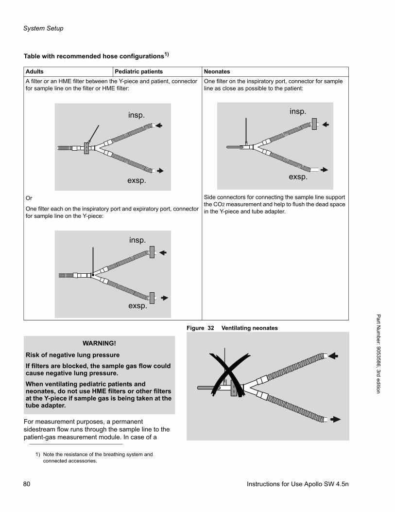
System Setup
Pa
rt Num
ber: 905358
6, 3rd edition
Table with recommended hose configurations1)
Figure 32 Ventilating neonates
For measurement purposes, a permanent sidestream flow runs through the sample line to the patient-gas measurement module. In case of a
1) Note the resistance of the breathing system and connected accessories.
Adults Pediatric patients Neonates
A filter or an HME filter between the Y-piece and patient, connector for sample line on the filter or HME filter:
Or
One filter each on the inspiratory port and expiratory port, connector for sample line on the Y-piece:
One filter on the inspiratory port, connector for sample line as close as possible to the patient:
Side connectors for connecting the sample line support the CO2 measurement and help to flush the dead space in the Y-piece and tube adapter.
insp.
exsp.
insp.
exsp.
insp.
exsp.
WARNING!
Risk of negative lung pressure
If filters are blocked, the sample gas flow could cause negative lung pressure.
When ventilating pediatric patients and neonates, do not use HME filters or other filters at the Y-piece if sample gas is being taken at the tube adapter.
80 Instructions for Use Apollo SW 4.5n
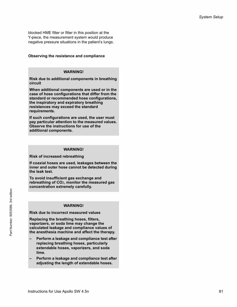
System Setup
Par
t Num
ber:
905
3586
, 3rd
edi
tion
blocked HME filter or filter in this position at the Y-piece, the measurement system would produce negative pressure situations in the patient’s lungs.
Observing the resistance and compliance
WARNING!
Risk due to additional components in breathing circuit
When additional components are used or in the case of hose configurations that differ from the standard or recommended hose configurations, the inspiratory and expiratory breathing resistances may exceed the standard requirements.
If such configurations are used, the user must pay particular attention to the measured values. Observe the instructions for use of the additional components.
WARNING!
Risk of increased rebreathing
If coaxial hoses are used, leakages between the inner and outer hose cannot be detected during the leak test.
To avoid insufficient gas exchange and rebreathing of CO2, monitor the measured gas concentration extremely carefully.
WARNING!
Risk due to incorrect measured values
Replacing the breathing hoses, filters, vaporizers, or soda lime may change the calculated leakage and compliance values of the anesthesia machine and affect the therapy.
– Perform a leakage and compliance test after replacing breathing hoses, particularly extendable hoses, vaporizers, and soda lime.
– Perform a leakage and compliance test after adjusting the length of extendable hoses.
Instructions for Use Apollo SW 4.5n 81

System Setup
Pa
rt Num
ber: 905358
6, 3rd edition
During spontaneous breathing, higher resistance values mean that the patient must do more breathing work.
In volume-controlled ventilation, an increased resistance has a slight effect on the applied volume during the inspiration. However, the peak pressure increases at a constant plateau pressure. For this reason, the time constant increases during the expiratory phase. If the expiration times are too short, the lungs might not be emptied completely, resulting in a dynamic overfilling of the lungs (air trapping).
In pressure-controlled ventilation, an increased resistance can reduce the inspiratory or expiratory volume.
Before the self test is performed, all accessories1) to be used must be connected. The extendable hoses must be drawn out to the length required by the user. This is the only way of ensuring that the compliance of the breathing system and breathing hoses is determined correctly and a corrected tidal volume is automatically applied during volume-controlled ventilation.
WARNING!
Risk when adjusting the hose length
When the hose length is changed, resistance and compliance may change. This can result in an increased or reduced ventilation volume for neonates.
Do not use extendable hoses, particularly for neonates.
1) If necessary, take into consideration additional parts such as water traps or additional hoses.
82 Instructions for Use Apollo SW 4.5n

System Setup
Par
t Num
ber:
905
3586
, 3rd
edi
tion
Calculating the resistance of the breathing sys-tem and connected accessories
To keep the patients' work of breathing as low as possible, according to ISO 8835-2 and ISO 80601-2-13 a total inspiratory and expiratory resistance of 6.0 hPa (cmH2O) at 60 L/min may not be exceeded.
The "Specifications" chapter states the inspiratory and expiratory breathing resistance of the breathing system, not including the breathing hoses. This allows for the calculation of the resistance of the breathing circuit using different hose sets and/or filters.
The following formula are used to calculate the resistance (R):
RInspiration =
RBreathingsystem_insp + RInspHose + RBagHose + RInsp-Filter(port) + RInspFilter(Y-piece)
RExpiration =
RBreathingsystem_exp + RExpHose + RExpFilter(port) + RExpFilter(Y-piece)
When calculating the resistance, only accessory resistance values and peak flows must be used that are applicable for the respective accessory category and patient category, e.g., resistance value for adults (60 L/min), for children (30 L/min), or for neonates (5 L/min).
Instructions for Use Apollo SW 4.5n 83
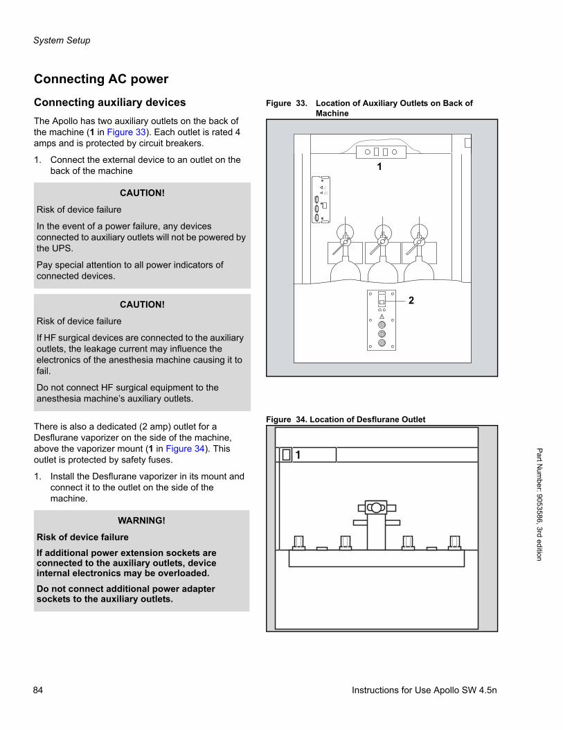
System Setup
Pa
rt Num
ber: 905358
6, 3rd edition
Connecting AC power
Figure 33. Location of Auxiliary Outlets on Back of Machine
Connecting auxiliary devices
The Apollo has two auxiliary outlets on the back of the machine (1 in Figure 33). Each outlet is rated 4 amps and is protected by circuit breakers.
1. Connect the external device to an outlet on the back of the machine
Figure 34. Location of Desflurane OutletThere is also a dedicated (2 amp) outlet for a Desflurane vaporizer on the side of the machine, above the vaporizer mount (1 in Figure 34). This outlet is protected by safety fuses.
1. Install the Desflurane vaporizer in its mount and connect it to the outlet on the side of the machine.
1
2C
OM
1C
OM
2IV
Sys
tem
SpO
2!
Cau
tion!
Con
sult
Acco
mpa
nyin
gD
ocum
ents
ESD
Sene
ltivi
ty
!
2
1
CAUTION!
Risk of device failure
In the event of a power failure, any devices connected to auxiliary outlets will not be powered by the UPS.
Pay special attention to all power indicators of connected devices.
CAUTION!
Risk of device failure
If HF surgical devices are connected to the auxiliary outlets, the leakage current may influence the electronics of the anesthesia machine causing it to fail.
Do not connect HF surgical equipment to the anesthesia machine’s auxiliary outlets.
1
WARNING!
Risk of device failure
If additional power extension sockets are connected to the auxiliary outlets, device internal electronics may be overloaded.
Do not connect additional power adapter sockets to the auxiliary outlets.
84 Instructions for Use Apollo SW 4.5n
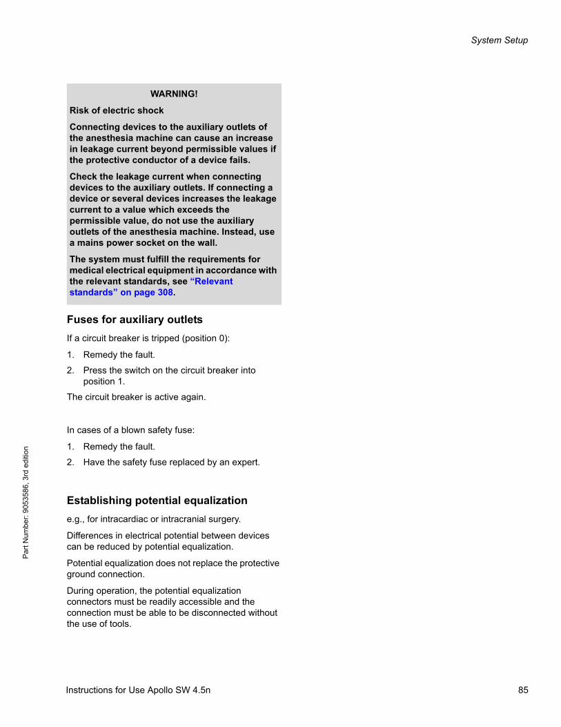
System Setup
Par
t Num
ber:
905
3586
, 3rd
edi
tion
Fuses for auxiliary outlets
If a circuit breaker is tripped (position 0):
1. Remedy the fault.
2. Press the switch on the circuit breaker into position 1.
The circuit breaker is active again.
In cases of a blown safety fuse:
1. Remedy the fault.
2. Have the safety fuse replaced by an expert.
Establishing potential equalization
e.g., for intracardiac or intracranial surgery.
Differences in electrical potential between devices can be reduced by potential equalization.
Potential equalization does not replace the protective ground connection.
During operation, the potential equalization connectors must be readily accessible and the connection must be able to be disconnected without the use of tools.
WARNING!
Risk of electric shock
Connecting devices to the auxiliary outlets of the anesthesia machine can cause an increase in leakage current beyond permissible values if the protective conductor of a device fails.
Check the leakage current when connecting devices to the auxiliary outlets. If connecting a device or several devices increases the leakage current to a value which exceeds the permissible value, do not use the auxiliary outlets of the anesthesia machine. Instead, use a mains power socket on the wall.
The system must fulfill the requirements for medical electrical equipment in accordance with the relevant standards, see “Relevant standards” on page 308.
Instructions for Use Apollo SW 4.5n 85
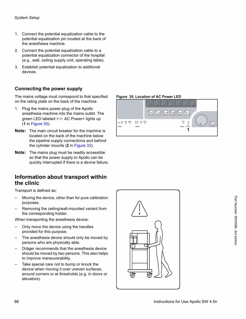
System Setup
Pa
rt Num
ber: 905358
6, 3rd edition
1. Connect the potential equalization cable to the potential equalization pin located at the back of the anesthesia machine.
2. Connect the potential equalization cable to a potential equalization connector of the hospital (e.g., wall, ceiling supply unit, operating table).
3. Establish potential equalization to additional devices.
Connecting the power supply
Figure 35. Location of AC Power LEDThe mains voltage must correspond to that specified on the rating plate on the back of the machine.
1. Plug the mains power plug of the Apollo anesthesia machine into the mains outlet. The green LED labeled >N AC Power< lights up(1 in Figure 35).
Note: The main circuit breaker for the machine is located on the back of the machine below the pipeline supply connections and behind the cylinder mounts (2 in Figure 33).
Note: The mains plug must be readily accessible so that the power supply to Apollo can be quickly interrupted if there is a device failure.
Information about transport within the clinicTransport is defined as:
– Moving the device, other than for pure calibration purposes.
– Removing the ceiling/wall-mounted variant from the corresponding holder.
When transporting the anesthesia device:
– Only move the device using the handles provided for this purpose.
– The anesthesia device should only be moved by persons who are physically able.
– Dräger recommends that the anesthesia device should be moved by two persons. This also helps to improve maneuverability.
– Take special care not to bump or knock the device when moving it over uneven surfaces, around corners or at thresholds (e.g. in doors or elevators).
1
Vol. AFMode
86 Instructions for Use Apollo SW 4.5n
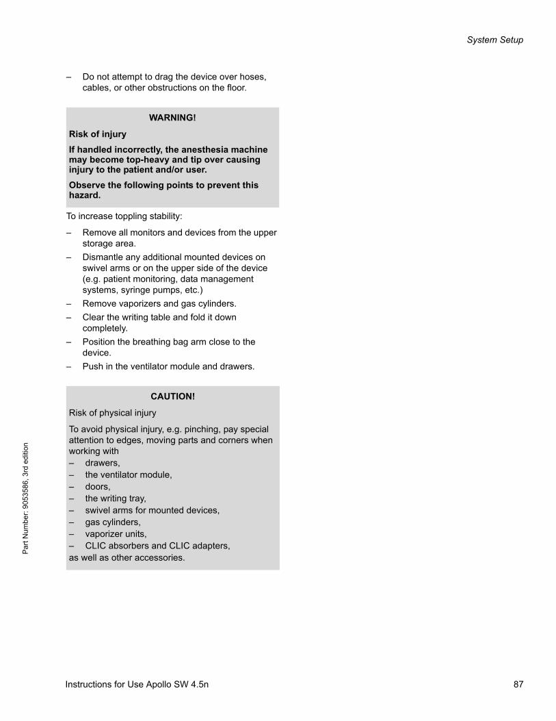
System Setup
Par
t Num
ber:
905
3586
, 3rd
edi
tion
– Do not attempt to drag the device over hoses, cables, or other obstructions on the floor.
To increase toppling stability:
– Remove all monitors and devices from the upper storage area.
– Dismantle any additional mounted devices on swivel arms or on the upper side of the device (e.g. patient monitoring, data management systems, syringe pumps, etc.)
– Remove vaporizers and gas cylinders.
– Clear the writing table and fold it down completely.
– Position the breathing bag arm close to the device.
– Push in the ventilator module and drawers.
WARNING!
Risk of injury
If handled incorrectly, the anesthesia machine may become top-heavy and tip over causing injury to the patient and/or user.
Observe the following points to prevent this hazard.
CAUTION!
Risk of physical injury
To avoid physical injury, e.g. pinching, pay special attention to edges, moving parts and corners when working with– drawers,– the ventilator module,– doors,– the writing tray,– swivel arms for mounted devices,– gas cylinders,– vaporizer units,– CLIC absorbers and CLIC adapters,as well as other accessories.
Instructions for Use Apollo SW 4.5n 87

System Setup
Pa
rt Num
ber: 905358
6, 3rd edition
This page intentionally left blank.
88 Instructions for Use Apollo SW 4.5n
Pre-use Checkout
Par
t Num
ber:
905
3586
, 3rd
edi
tion
Pre-use Checkout
ContentsOverview . . . . . . . . . . . . . . . . . . . . . . . . . . . . . . . . . . . . . . . . . . . . . . . . . . . . . . . . . . . . . . . . . . . . . . . . . . . . . . . 91
Checking the Workstation according to the Check List . . . . . . . . . . . . . . . . . . . . . . . . . . . . . . . . . . . . . . . . . 91
Prerequisites . . . . . . . . . . . . . . . . . . . . . . . . . . . . . . . . . . . . . . . . . . . . . . . . . . . . . . . . . . . . . . . . . . . . . . . . . . . . . 91
Power on . . . . . . . . . . . . . . . . . . . . . . . . . . . . . . . . . . . . . . . . . . . . . . . . . . . . . . . . . . . . . . . . . . . . . . . . . . . . . . . 93
Check list . . . . . . . . . . . . . . . . . . . . . . . . . . . . . . . . . . . . . . . . . . . . . . . . . . . . . . . . . . . . . . . . . . . . . . . . . . . . . . . 93
Self test . . . . . . . . . . . . . . . . . . . . . . . . . . . . . . . . . . . . . . . . . . . . . . . . . . . . . . . . . . . . . . . . . . . . . . . . . . . . . . . 100
Self test results . . . . . . . . . . . . . . . . . . . . . . . . . . . . . . . . . . . . . . . . . . . . . . . . . . . . . . . . . . . . . . . . . . . . . . . . . . 102
System compliance . . . . . . . . . . . . . . . . . . . . . . . . . . . . . . . . . . . . . . . . . . . . . . . . . . . . . . . . . . . . . . . . . . . . . 103
Leak tests . . . . . . . . . . . . . . . . . . . . . . . . . . . . . . . . . . . . . . . . . . . . . . . . . . . . . . . . . . . . . . . . . . . . . . . . . . . . . 103
Leak system . . . . . . . . . . . . . . . . . . . . . . . . . . . . . . . . . . . . . . . . . . . . . . . . . . . . . . . . . . . . . . . . . . . . . . . . . . . . 103
Leak Man/Spont . . . . . . . . . . . . . . . . . . . . . . . . . . . . . . . . . . . . . . . . . . . . . . . . . . . . . . . . . . . . . . . . . . . . . . . . . 104
Locating and eliminating leaks . . . . . . . . . . . . . . . . . . . . . . . . . . . . . . . . . . . . . . . . . . . . . . . . . . . . . . . . . . . . . . 105
Additional suggestions to isolate components of the breathing system for leaks: . . . . . . . . . . . . . . . . . . . . . . . 106
Emergency start . . . . . . . . . . . . . . . . . . . . . . . . . . . . . . . . . . . . . . . . . . . . . . . . . . . . . . . . . . . . . . . . . . . . . . . . 107
Instructions for Use Apollo SW 4.5n 89

Pre-use Checkout
Pa
rt Num
ber: 905358
6, 3rd edition
This page intentionally left blank.
90 Instructions for Use Apollo SW 4.5n

Pre-use Checkout
Par
t Num
ber:
905
3586
, 3rd
edi
tion
OverviewThe pre-use checkout procedure must be performed to ensure that the Apollo is ready for use. This is a recommended procedure. Follow the institution’s policies for specific procedures.
If the Apollo fails any checkout routine, do not use the machine until corrective action is taken. If indicated, contact an authorized representative of DrägerService for inspection of the unit.
Checking the Workstation accord-ing to the Check ListThe pre-use checkout procedure consists of a manual procedure performed by the user, followed by an automated self test. The manual procedure is summarized in the check list that is displayed after the machine is powered on.
Prerequisites
The device has been prepared (see “Cleaning and Maintenance” on page 225) and assembled ready for operation.
The pipeline supply and the power supply must be connected.
WARNING!
Risk of device failure and/or patient injury
Do not insert any additional components into or modify the Apollo after the checkout procedure has been started.
The anesthesia machine will not meet the specified technical data.
WARNING!
Risk of patient injury
Inappropriate hose length affects compliance and can result in incorrect tidal volume delivery to the patient.
Patient hoses must be adjusted to the appropriate lengths prior to performing the leak and compliance tests.
Instructions for Use Apollo SW 4.5n 91
Pre-use Checkout
Pa
rt Num
ber: 905358
6, 3rd edition
WARNING!
Risk of explosion, fire
If an oxygen leak is suspected within or near the inhalation anesthesia machine, do not initiate operation.
Disconnect all oxygen supplies and contact a trained service technician.
CAUTION!
Risk of inadvertent movement
If not properly secured, the device may move inadvertently during operation.
Apply the brakes on the device to ensure it cannot be moved accidentally.
WARNING!
Risk of electric shock
Connect the electrical power cable to a hospital-grade live AC receptacle that accepts and properly grounds the power cable. Do not use “cheater plugs”. The term “cheater plug” implies any and all electrical plugs or other devices that can inhibit or prohibit the proper grounding of the anesthesia machine.
92 Instructions for Use Apollo SW 4.5n
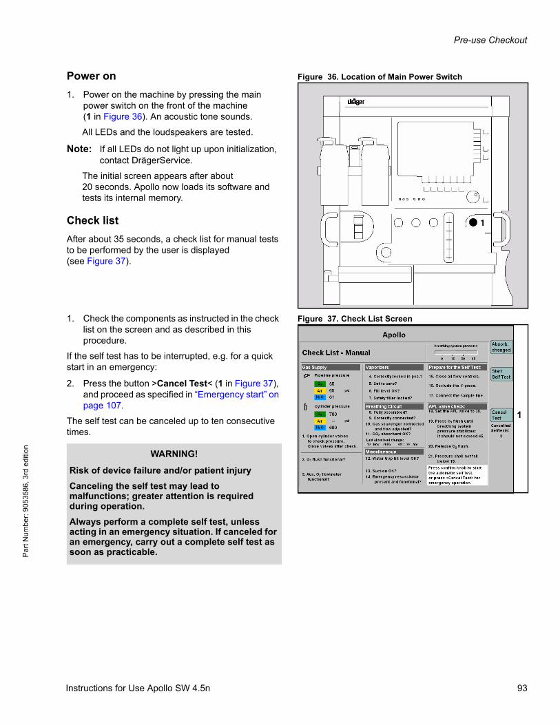
Pre-use Checkout
Par
t Num
ber:
905
3586
, 3rd
edi
tion
Figure 36. Location of Main Power SwitchPower on
1. Power on the machine by pressing the main power switch on the front of the machine(1 in Figure 36). An acoustic tone sounds.
All LEDs and the loudspeakers are tested.
Note: If all LEDs do not light up upon initialization, contact DrägerService.
The initial screen appears after about 20 seconds. Apollo now loads its software and tests its internal memory.
Check list
After about 35 seconds, a check list for manual tests to be performed by the user is displayed(see Figure 37).
Figure 37. Check List Screen1. Check the components as instructed in the check list on the screen and as described in this procedure.
If the self test has to be interrupted, e.g. for a quick start in an emergency:
2. Press the button >Cancel Test< (1 in Figure 37), and proceed as specified in “Emergency start” on page 107.
The self test can be canceled up to ten consecutive times.
1
WARNING!
Risk of device failure and/or patient injury
Canceling the self test may lead to malfunctions; greater attention is required during operation.
Always perform a complete self test, unless acting in an emergency situation. If canceled for an emergency, carry out a complete self test as soon as practicable.
Instructions for Use Apollo SW 4.5n 93
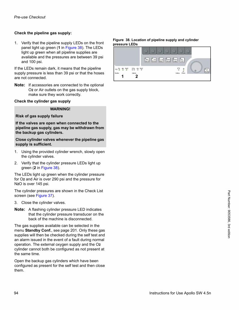
Pre-use Checkout
Pa
rt Num
ber: 905358
6, 3rd edition
Check the pipeline gas supply:
Figure 38. Location of pipeline supply and cylinder pressure LEDs1. Verify that the pipeline supply LEDs on the front
panel light up green (1 in Figure 38). The LEDs light up green when all pipeline supplies are available and the pressures are between 39 psi and 100 psi.
If the LEDs remain dark, it means that the pipeline supply pressure is less than 39 psi or that the hoses are not connected.
Note: If accessories are connected to the optional O2 or Air outlets on the gas supply block, make sure they work correctly.
Check the cylinder gas supply
1. Using the provided cylinder wrench, slowly open the cylinder valves.
2. Verify that the cylinder pressure LEDs light up green (2 in Figure 38).
The LEDs light up green when the cylinder pressure for O2 and Air is over 290 psi and the pressure for N2O is over 145 psi.
The cylinder pressures are shown in the Check List screen (see Figure 37).
3. Close the cylinder valves.
Note: A flashing cylinder pressure LED indicates that the cylinder pressure transducer on the back of the machine is disconnected.
The gas supplies available can be selected in the menu Standby Conf., see page 201. Only these gas supplies will then be checked during the self test and an alarm issued in the event of a fault during normal operation. The external oxygen supply and the O2 cylinder cannot both be configured as not present at the same time.
Open the backup gas cylinders which have been configured as present for the self test and then close them.
1 2
Vol. AFMode
WARNING!
Risk of gas supply failure
If the valves are open when connected to the pipeline gas supply, gas may be withdrawn from the backup gas cylinders.
Close cylinder valves whenever the pipeline gas supply is sufficient.
94 Instructions for Use Apollo SW 4.5n
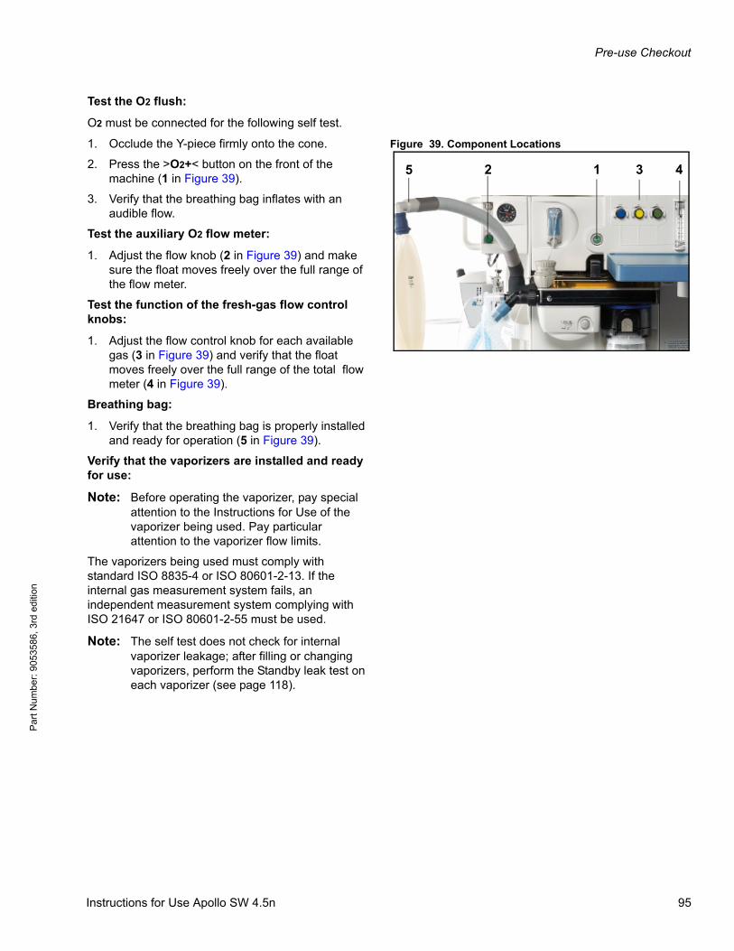
Pre-use Checkout
Par
t Num
ber:
905
3586
, 3rd
edi
tion
Test the O2 flush:
O2 must be connected for the following self test.
Figure 39. Component Locations1. Occlude the Y-piece firmly onto the cone.
2. Press the >O2+< button on the front of the machine (1 in Figure 39).
3. Verify that the breathing bag inflates with an audible flow.
Test the auxiliary O2 flow meter:
1. Adjust the flow knob (2 in Figure 39) and make sure the float moves freely over the full range of the flow meter.
Test the function of the fresh-gas flow control knobs:
1. Adjust the flow control knob for each available gas (3 in Figure 39) and verify that the float moves freely over the full range of the total flow meter (4 in Figure 39).
Breathing bag:
1. Verify that the breathing bag is properly installed and ready for operation (5 in Figure 39).
Verify that the vaporizers are installed and ready for use:
Note: Before operating the vaporizer, pay special attention to the Instructions for Use of the vaporizer being used. Pay particular attention to the vaporizer flow limits.
The vaporizers being used must comply with standard ISO 8835-4 or ISO 80601-2-13. If the internal gas measurement system fails, an independent measurement system complying with ISO 21647 or ISO 80601-2-55 must be used.
Note: The self test does not check for internal vaporizer leakage; after filling or changing vaporizers, perform the Standby leak test on each vaporizer (see page 118).
2 1 3 45
Instructions for Use Apollo SW 4.5n 95
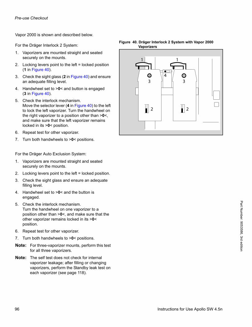
Pre-use Checkout
Pa
rt Num
ber: 905358
6, 3rd edition
Vapor 2000 is shown and described below.
Figure 40. Dräger Interlock 2 System with Vapor 2000 VaporizersFor the Dräger Interlock 2 System:
1. Vaporizers are mounted straight and seated securely on the mounts.
2. Locking levers point to the left = locked position (1 in Figure 40).
3. Check the sight glass (2 in Figure 40) and ensure an adequate filling level.
4. Handwheel set to >0< and button is engaged(3 in Figure 40).
5. Check the interlock mechanism.Move the selector lever (4 in Figure 40) to the left to lock the left vaporizer. Turn the handwheel on the right vaporizer to a position other than >0<, and make sure that the left vaporizer remains locked in its >0< position.
6. Repeat test for other vaporizer.
7. Turn both handwheels to >0< positions.
For the Dräger Auto Exclusion System:
1. Vaporizers are mounted straight and seated securely on the mounts.
2. Locking levers point to the left = locked position.
3. Check the sight glass and ensure an adequate filling level.
4. Handwheel set to >0< and the button is engaged.
5. Check the interlock mechanism.Turn the handwheel on one vaporizer to a position other than >0<, and make sure that the other vaporizer remains locked in its >0< position.
6. Repeat test for other vaporizer.
7. Turn both handwheels to >0< positions.
Note: For three-vaporizer mounts, perform this test for all three vaporizers.
Note: The self test does not check for internal vaporizer leakage; after filling or changing vaporizers, perform the Standby leak test on each vaporizer (see page 118).
1 1
4 00
33
2 2
96 Instructions for Use Apollo SW 4.5n
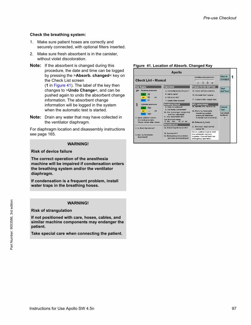
Pre-use Checkout
Par
t Num
ber:
905
3586
, 3rd
edi
tion
Check the breathing system:
1. Make sure patient hoses are correctly and securely connected, with optional filters inserted.
2. Make sure fresh absorbent is in the canister, without violet discoloration.
Figure 41. Location of Absorb. Changed KeyNote: If the absorbent is changed during this procedure, the date and time can be logged by pressing the >Absorb. changed< key on the Check List screen(1 in Figure 41). The label of the key then changes to >Undo Change<, and can be pushed again to undo the absorbent change information. The absorbent change information will be logged in the system when the automatic test is started.
Note: Drain any water that may have collected in the ventilator diaphragm.
For diaphragm location and disassembly instructions see page 165.
1
WARNING!
Risk of device failure
The correct operation of the anesthesia machine will be impaired if condensation enters the breathing system and/or the ventilator diaphragm.
If condensation is a frequent problem, install water traps in the breathing hoses.
WARNING!
Risk of strangulation
If not positioned with care, hoses, cables, and similar machine components may endanger the patient.
Take special care when connecting the patient.
Instructions for Use Apollo SW 4.5n 97

Pre-use Checkout
Pa
rt Num
ber: 905358
6, 3rd edition
Note the Instructions for Use of the Drägersorb 800 + or Drägersorb Free soda lime.
Verify that the scavenging system is ready for use:
1. Check that the scavenger hose between the AGS and the scavenger connection on back of the machine is securely connected.
2. Check that the hose between the output connector on the scavenger and the hospital waste-gas disposal system is securely connected.
3. Make sure that the AGSS is ready for operation. Check if the flow indicator at the AGS floats between the two marks.
4. On the AGS, make sure that the float is in between the two marks in the sight glass on the AGS.
WARNING!
Risk of patient injury
The soda lime loses humidity. Generally, if the humidity falls below a minimum set point, the following undesirable reactions can occur, independent of the type of lime and the inhalation anesthetic being used:
– reduced CO2 absorption,– increased heat build-up in the absorber and
thus an increased breathing gas temperature,
– formation of CO,– absorption and/or decomposition of the
anesthetic agent.These reactions could pose a danger to the patient.
If using dry gases, only flush the anesthesia system briefly, and only if necessary.
WARNING!
Risk of patient injury
If the flow controls are left open, the ensuing flow of gas may dry out the soda lime, endangering the patient.
The flow control valves should be closed when the machine is in the standby mode or when it is switched off.
98 Instructions for Use Apollo SW 4.5n
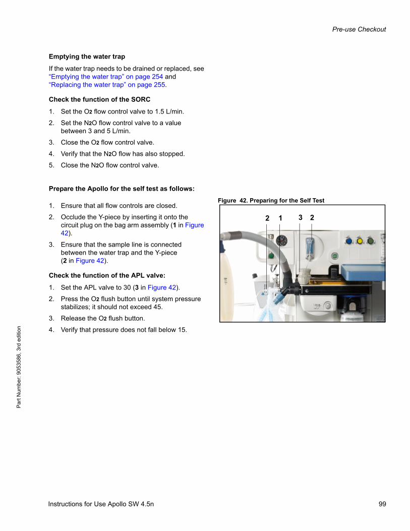
Pre-use Checkout
Par
t Num
ber:
905
3586
, 3rd
edi
tion
Emptying the water trap
If the water trap needs to be drained or replaced, see “Emptying the water trap” on page 254 and “Replacing the water trap” on page 255.
Check the function of the SORC
1. Set the O2 flow control valve to 1.5 L/min.
2. Set the N2O flow control valve to a value between 3 and 5 L/min.
3. Close the O2 flow control valve.
4. Verify that the N2O flow has also stopped.
5. Close the N2O flow control valve.
Prepare the Apollo for the self test as follows:
Figure 42. Preparing for the Self Test1. Ensure that all flow controls are closed.
2. Occlude the Y-piece by inserting it onto the circuit plug on the bag arm assembly (1 in Figure 42).
3. Ensure that the sample line is connected between the water trap and the Y-piece(2 in Figure 42).
Check the function of the APL valve:
1. Set the APL valve to 30 (3 in Figure 42).
2. Press the O2 flush button until system pressure stabilizes; it should not exceed 45.
3. Release the O2 flush button.
4. Verify that pressure does not fall below 15.
1 22 3
Instructions for Use Apollo SW 4.5n 99
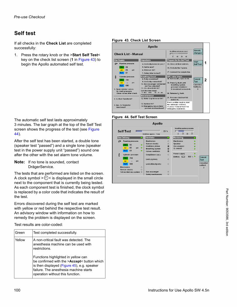
Pre-use Checkout
Pa
rt Num
ber: 905358
6, 3rd edition
Self testFigure 43. Check List Screen
If all checks in the Check List are completed successfully:
1. Press the rotary knob or the >Start Self Test< key on the check list screen (1 in Figure 43) to begin the Apollo automated self test.
Figure 44. Self Test ScreenThe automatic self test lasts approximately 3 minutes. The bar graph at the top of the Self Test screen shows the progress of the test (see Figure 44).
After the self test has been started, a double tone (speaker test ”passed”) and a single tone (speaker test in the power supply unit “passed”) sound one after the other with the set alarm tone volume.
Note: If no tone is sounded, contact DrägerService.
The tests that are performed are listed on the screen. A clock symbol > < is displayed in the small circle next to the component that is currently being tested. As each component test is finished, the clock symbol is replaced by a color code that indicates the result of the test.
Errors discovered during the self test are marked with yellow or red behind the respective test result. An advisory window with information on how to remedy the problem is displayed on the screen.
Test results are color-coded:
1
2
Green Test completed successfully.
Yellow A non-critical fault was detected. Theanesthesia machine can be used with restrictions.
Functions highlighted in yellow canbe confirmed with the >Accept< button which is then displayed (Figure 45), e.g. speaker failure. The anesthesia machine starts operation without this function.
100 Instructions for Use Apollo SW 4.5n
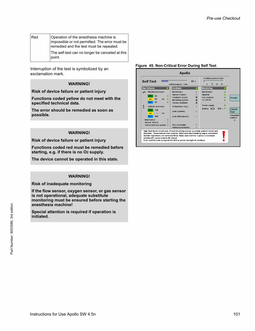
Pre-use Checkout
Par
t Num
ber:
905
3586
, 3rd
edi
tion
Figure 45. Non-Critical Error During Self TestInterruption of the test is symbolized by an exclamation mark.
Red Operation of the anesthesia machine is impossible or not permitted. The error must be remedied and the test must be repeated.
The self-test can no longer be canceled at this point.
WARNING!
Risk of device failure or patient injury
Functions coded yellow do not meet with the specified technical data.
The error should be remedied as soon as possible.
WARNING!
Risk of device failure or patient injury
Functions coded red must be remedied before starting, e.g. if there is no O2 supply.
The device cannot be operated in this state.
WARNING!
Risk of inadequate monitoring
If the flow sensor, oxygen sensor, or gas sensor is not operational, adequate substitute monitoring must be ensured before starting the anesthesia machine!
Special attention is required if operation is initiated.
Instructions for Use Apollo SW 4.5n 101
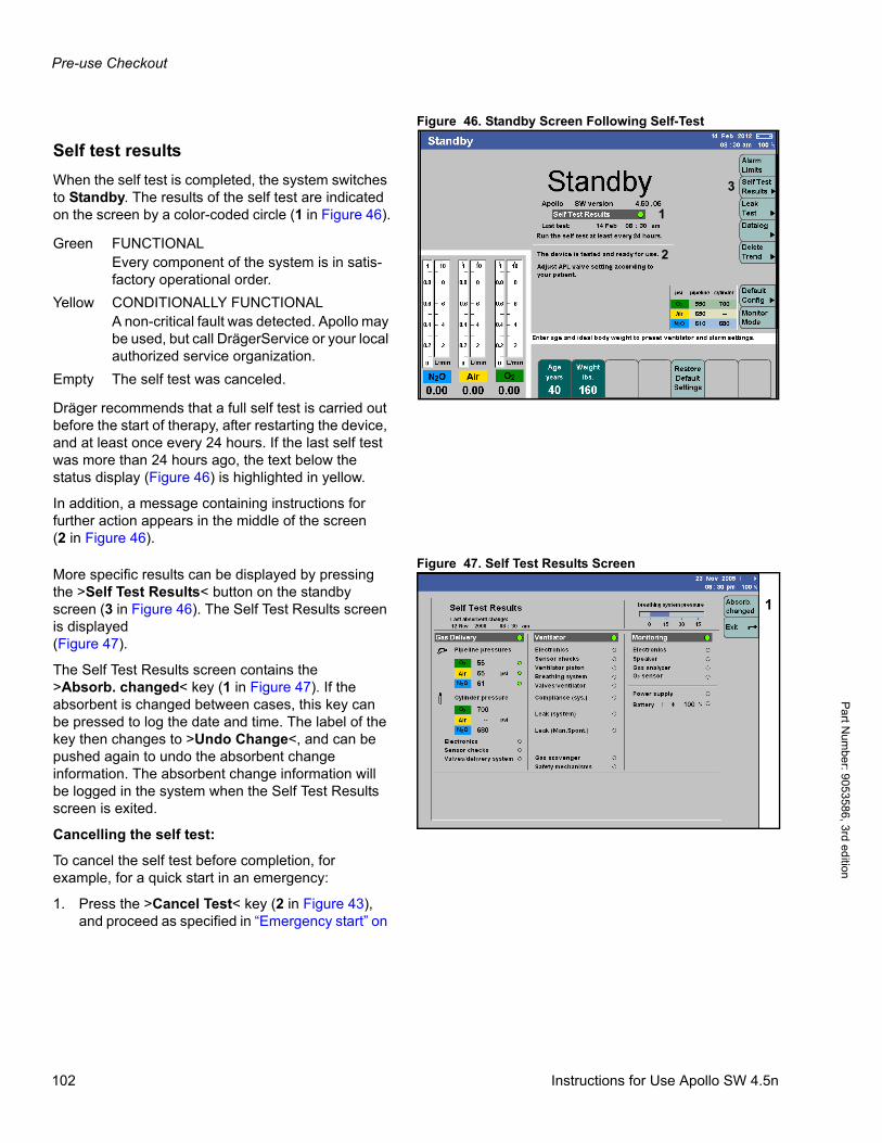
Pre-use Checkout
Pa
rt Num
ber: 905358
6, 3rd edition
Figure 46. Standby Screen Following Self-Test
Self test results
When the self test is completed, the system switches to Standby. The results of the self test are indicated on the screen by a color-coded circle (1 in Figure 46).
Dräger recommends that a full self test is carried out before the start of therapy, after restarting the device, and at least once every 24 hours. If the last self test was more than 24 hours ago, the text below the status display (Figure 46) is highlighted in yellow.
In addition, a message containing instructions for further action appears in the middle of the screen (2 in Figure 46).
Figure 47. Self Test Results ScreenMore specific results can be displayed by pressing the >Self Test Results< button on the standby screen (3 in Figure 46). The Self Test Results screen is displayed(Figure 47).
The Self Test Results screen contains the>Absorb. changed< key (1 in Figure 47). If the absorbent is changed between cases, this key can be pressed to log the date and time. The label of the key then changes to >Undo Change<, and can be pushed again to undo the absorbent change information. The absorbent change information will be logged in the system when the Self Test Results screen is exited.
Cancelling the self test:
To cancel the self test before completion, for example, for a quick start in an emergency:
1. Press the >Cancel Test< key (2 in Figure 43), and proceed as specified in “Emergency start” on
1
3
2Green FUNCTIONAL
Every component of the system is in satis-factory operational order.
Yellow CONDITIONALLY FUNCTIONALA non-critical fault was detected. Apollo may be used, but call DrägerService or your local authorized service organization.
Empty The self test was canceled.
1
102 Instructions for Use Apollo SW 4.5n

Pre-use Checkout
Par
t Num
ber:
905
3586
, 3rd
edi
tion
page 107. The self test can be canceled up to ten consecutive times.
System complianceApollo determines the current compliance of the breathing circuit consisting of filters, hoses, and a Y-piece. Typical values for the inspiratory system compliance are between 0.5 and 2.6 mL/hPa (mL/cmH2O).
In volume-controlled ventilation, system compliance is compensated. For this purpose, Apollo increases the applied tidal volume on the basis of the difference between PEEP and plateau pressure in accordance with the determined compliance value.
Leak testsThe Apollo tests for leaks in the mechanical subsystem and in the Man/Spont system.
Leak system
Figure 48. Mechanical Ventilation Leak Test– Figure 48 shows the components tested in the
mechanical ventilation branch.
– This branch is tested with positive pressure.
– Leaks are indicated on the Self Test Results screen by the yellow/green test result indicator and by posting the leak value in mL/min (Leak (system) test result in Figure 47).
WARNING!
Risk of device failure and/or patient injury
Canceling the self test may lead to malfunctions. Special attention is required during operation.
Always perform a complete self test, unless acting in an emergency situation. If canceled for an emergency situation, perform a complete self test as soon as practicable.
Instructions for Use Apollo SW 4.5n 103
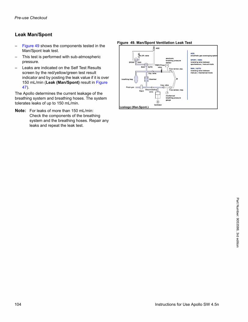
Pre-use Checkout
Pa
rt Num
ber: 905358
6, 3rd edition
Leak Man/Spont
Figure 49. Man/Spont Ventilation Leak Test– Figure 49 shows the components tested in the
Man/Spont leak test.
– This test is performed with sub-atmospheric pressure.
– Leaks are indicated on the Self Test Results screen by the red/yellow/green test result indicator and by posting the leak value if it is over 150 mL/min (Leak (Man/Spont) result in Figure 47).
The Apollo determines the current leakage of the breathing system and breathing hoses. The system tolerates leaks of up to 150 mL/min.
Note: For leaks of more than 150 mL/min:Check the components of the breathing system and the breathing hoses. Repair any leaks and repeat the leak test.
104 Instructions for Use Apollo SW 4.5n
Pre-use Checkout
Par
t Num
ber:
905
3586
, 3rd
edi
tion
Locating and eliminating leaks
The self test incorporates a leak test. If this test is not passed, the leaks must be remedied before continuing the test by pressing the rotary knob. A leak test can also be carried out later in Standby with the >Leak Test< key.
Possible causes of leaks include:
– Absorber not firmly screwed to the breathing system.
– APL valve is not firmly fixed to the breathing system cover (damage) or not set to 30 hPa (cmH2O).
– Breathing bag, breathing hoses, Y-piece, or microbial filter are not connected correctly or damaged.
– Flexible arm for breathing bag not fitted correctly on the breathing system, sealing ring soiled or damaged.
– Water trap not connected.
– Sample line for gas measurement not connected or leaky (there may be a kinked bend in the connections).
– Connections for the sample line for gas measurement cracked or defective.
– O-ring of the inspiratory and expiratory ports missing, soiled, or damaged.
– Flow sensors not fitted correctly or damaged, rear O-ring missing.
– Breathing system cover not mounted correctly, not all five sealing screws closed.
– Visible damage on valves or seals of the breathing system metal valve plate.
– Breathing system not mounted correctly, not all three sealing screws closed.
– Ventilator diaphragm defective or not fitted correctly (Dräger legend must be visible from above).
– 15 mm (0.59 in) circuit plug for connecting the Y-piece scratched or damaged.
– Vaporizer fill or drain connections leaky or opened, vaporizer not mounted correctly, O-ring missing or handwheel not set to >0<.
Instructions for Use Apollo SW 4.5n 105

Pre-use Checkout
Pa
rt Num
ber: 905358
6, 3rd edition
Additional suggestions to isolate compo-nents of the breathing system for leaks:
Carry out the described measures:
Patient Sample Line Isolation:
1. Remove the sample line for gas measurement and seal the Luer Lock connection on theY-piece.
2. Perform leak test.
Exclude the breathing hoses from the leak test
1. Remove the patient circuit from the breathing system.
2. Install a leak-free hose between the inspiration and expiration ports. The breathing bag must be on the bag arm.
3. Perform leak test.
Isolation of Vaporizers:
1. Remove the vaporizers from the anesthesia machine.
2. Perform leak test.
Note: The self test does not check for internal vaporizer leakage; after filling or changing vaporizers, perform the Standby leak test on each vaporizer (see page 118).
106 Instructions for Use Apollo SW 4.5n
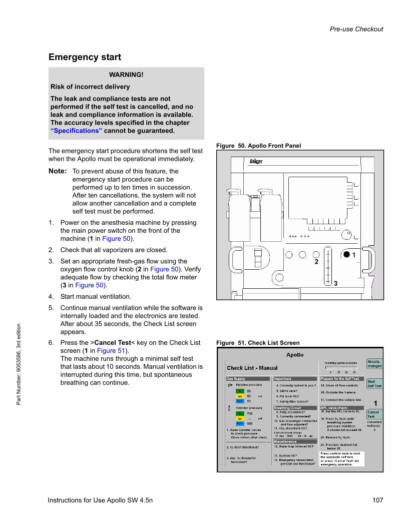
Pre-use Checkout
Par
t Num
ber:
905
3586
, 3rd
edi
tion
Emergency start
Figure 50. Apollo Front PanelThe emergency start procedure shortens the self test when the Apollo must be operational immediately.
Note: To prevent abuse of this feature, the emergency start procedure can be performed up to ten times in succession. After ten cancellations, the system will not allow another cancellation and a complete self test must be performed.
1. Power on the anesthesia machine by pressing the main power switch on the front of the machine (1 in Figure 50).
2. Check that all vaporizers are closed.
3. Set an appropriate fresh-gas flow using the oxygen flow control knob (2 in Figure 50). Verify adequate flow by checking the total flow meter(3 in Figure 50).
4. Start manual ventilation.
5. Continue manual ventilation while the software is internally loaded and the electronics are tested. After about 35 seconds, the Check List screen appears.
Figure 51. Check List Screen6. Press the >Cancel Test< key on the Check List screen (1 in Figure 51).The machine runs through a minimal self test that lasts about 10 seconds. Manual ventilation is interrupted during this time, but spontaneous breathing can continue.
WARNING!
Risk of incorrect delivery
The leak and compliance tests are not performed if the self test is cancelled, and no leak and compliance information is available. The accuracy levels specified in the chapter “Specifications” cannot be guaranteed.
2
3
1
Instructions for Use Apollo SW 4.5n 107
Pre-use Checkout
Pa
rt Num
ber: 905358
6, 3rd edition
Apollo is ready for operation about 1 minute after initiating. The O2 sensor is completely calibrated after about 5 minutes.
After the minimal self test, the anesthesia machine switches to Standby.
Note: The >Cancel Test< key is also available in the self test screen.
WARNING!
Risk of device failure and/or patient injury
Canceling the self test may lead to malfunctions; greater attention is required during operation.
Always perform a complete self test, unless acting in an emergency situation. If canceled for an emergency situation, carry out a complete self test as soon as practicable.
108 Instructions for Use Apollo SW 4.5n
Operation Summary
Par
t Num
ber:
905
3586
, 3rd
edi
tion
Operation Summary
ContentsOverview . . . . . . . . . . . . . . . . . . . . . . . . . . . . . . . . . . . . . . . . . . . . . . . . . . . . . . . . . . . . . . . . . . . . . . . . . . . . . . 111
Typical operation . . . . . . . . . . . . . . . . . . . . . . . . . . . . . . . . . . . . . . . . . . . . . . . . . . . . . . . . . . . . . . . . . . . . . . . 111
Loading default settings . . . . . . . . . . . . . . . . . . . . . . . . . . . . . . . . . . . . . . . . . . . . . . . . . . . . . . . . . . . . . . . . . . . 111
Entering the patient’s age . . . . . . . . . . . . . . . . . . . . . . . . . . . . . . . . . . . . . . . . . . . . . . . . . . . . . . . . . . . . . . . . . . 111
Entering the patient’s ideal body weight (Optional) . . . . . . . . . . . . . . . . . . . . . . . . . . . . . . . . . . . . . . . . . . . . . . 112
Setting the fresh-gas flow . . . . . . . . . . . . . . . . . . . . . . . . . . . . . . . . . . . . . . . . . . . . . . . . . . . . . . . . . . . . . . . . . . 113
Setting vaporizer concentration . . . . . . . . . . . . . . . . . . . . . . . . . . . . . . . . . . . . . . . . . . . . . . . . . . . . . . . . . . . . . 114
Setting ventilation mode . . . . . . . . . . . . . . . . . . . . . . . . . . . . . . . . . . . . . . . . . . . . . . . . . . . . . . . . . . . . . . . . . . . 115
Changing patients . . . . . . . . . . . . . . . . . . . . . . . . . . . . . . . . . . . . . . . . . . . . . . . . . . . . . . . . . . . . . . . . . . . . . . 115
Switch to standby mode . . . . . . . . . . . . . . . . . . . . . . . . . . . . . . . . . . . . . . . . . . . . . . . . . . . . . . . . . . . . . . . . . . . 115
Changing soda lime . . . . . . . . . . . . . . . . . . . . . . . . . . . . . . . . . . . . . . . . . . . . . . . . . . . . . . . . . . . . . . . . . . . . . 116
Reusable absorber . . . . . . . . . . . . . . . . . . . . . . . . . . . . . . . . . . . . . . . . . . . . . . . . . . . . . . . . . . . . . . . . . . . . . . . 116
Disposable CLIC absorber (Optional) . . . . . . . . . . . . . . . . . . . . . . . . . . . . . . . . . . . . . . . . . . . . . . . . . . . . . . . . . 117
Leak test . . . . . . . . . . . . . . . . . . . . . . . . . . . . . . . . . . . . . . . . . . . . . . . . . . . . . . . . . . . . . . . . . . . . . . . . . . . . . . 118
Activating the CO2 bypass function (Optional) . . . . . . . . . . . . . . . . . . . . . . . . . . . . . . . . . . . . . . . . . . . . . . . 119
End of operation . . . . . . . . . . . . . . . . . . . . . . . . . . . . . . . . . . . . . . . . . . . . . . . . . . . . . . . . . . . . . . . . . . . . . . . . 120
When Apollo is not in use . . . . . . . . . . . . . . . . . . . . . . . . . . . . . . . . . . . . . . . . . . . . . . . . . . . . . . . . . . . . . . . . 122
Instructions for Use Apollo SW 4.5n 109

Operation Summary
Pa
rt Num
ber: 905358
6, 3rd edition
This page intentionally left blank.
110 Instructions for Use Apollo SW 4.5n
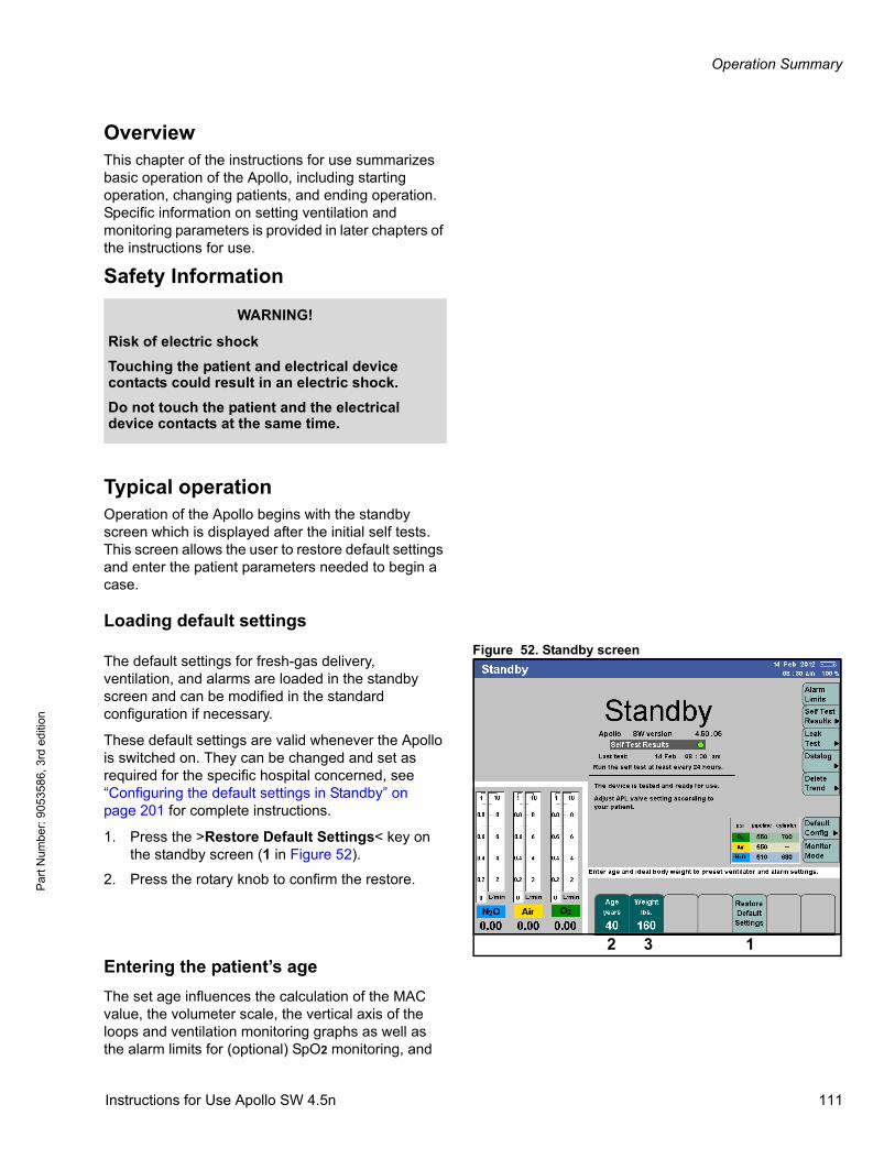
Operation Summary
Par
t Num
ber:
905
3586
, 3rd
edi
tion
OverviewThis chapter of the instructions for use summarizes basic operation of the Apollo, including starting operation, changing patients, and ending operation. Specific information on setting ventilation and monitoring parameters is provided in later chapters of the instructions for use.
Safety Information
Typical operationOperation of the Apollo begins with the standby screen which is displayed after the initial self tests. This screen allows the user to restore default settings and enter the patient parameters needed to begin a case.
Loading default settings
Figure 52. Standby screenThe default settings for fresh-gas delivery, ventilation, and alarms are loaded in the standby screen and can be modified in the standard configuration if necessary.
These default settings are valid whenever the Apollo is switched on. They can be changed and set as required for the specific hospital concerned, see “Configuring the default settings in Standby” on page 201 for complete instructions.
1. Press the >Restore Default Settings< key on the standby screen (1 in Figure 52).
2. Press the rotary knob to confirm the restore.
Entering the patient’s age
The set age influences the calculation of the MAC value, the volumeter scale, the vertical axis of the loops and ventilation monitoring graphs as well as the alarm limits for (optional) SpO2 monitoring, and
WARNING!
Risk of electric shock
Touching the patient and electrical device contacts could result in an electric shock.
Do not touch the patient and the electrical device contacts at the same time.
12 3
Instructions for Use Apollo SW 4.5n 111
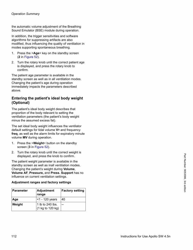
Operation Summary
Pa
rt Num
ber: 905358
6, 3rd edition
the automatic volume adjustment of the Breathing Sound Emulator (BSE) module during operation.
In addition, the trigger sensitivities and software algorithms for suppressing artifacts are also modified, thus influencing the quality of ventilation in modes supporting spontaneous breathing.
1. Press the >Age< key on the standby screen(2 in Figure 52).
2. Turn the rotary knob until the correct patient age is displayed, and press the rotary knob to confirm.
The patient age parameter is available in the standby screen as well as in all ventilation modes. Changing the patient’s age during operation immediately impacts the parameters described above.
Entering the patient’s ideal body weight (Optional)
The patient’s ideal body weight describes that proportion of the body relevant to setting the ventilation parameters (the patient’s body weight minus the assumed excess fat).
The set ideal body weight influences the ventilator default settings for tidal volume VT and frequency freq, as well as the alarm limits for expiratory minute volume MV during operation.
1. Press the >Weight< button on the standby screen (3 in Figure 52).
2. Turn the rotary knob until the correct weight is displayed, and press the knob to confirm.
The patient weight parameter is available in the standby screen as well as inall ventilation modes. Changing the patient’s weight during Volume, Volume AF, Pressure, and Press. Support has no influence on current ventilation settings.
Adjustment ranges and factory settings
Parameter Adjustment range
Factory setting
Age <1 - 120 years 40
Weight 1 lb to 240 lbs.(1 kg to 120 kg)
--
112 Instructions for Use Apollo SW 4.5n
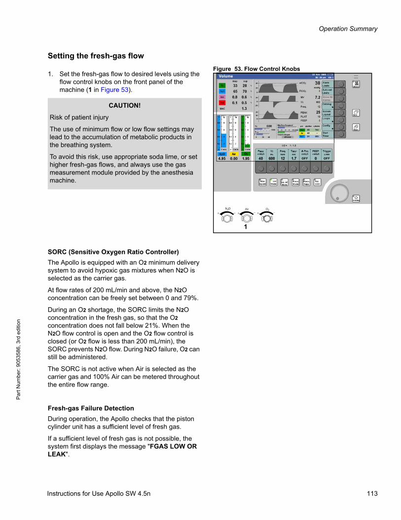
Operation Summary
Par
t Num
ber:
905
3586
, 3rd
edi
tion
Setting the fresh-gas flow
Figure 53. Flow Control Knobs1. Set the fresh-gas flow to desired levels using the
flow control knobs on the front panel of the machine (1 in Figure 53).
SORC (Sensitive Oxygen Ratio Controller)
The Apollo is equipped with an O2 minimum delivery system to avoid hypoxic gas mixtures when N2O is selected as the carrier gas.
At flow rates of 200 mL/min and above, the N2O concentration can be freely set between 0 and 79%.
During an O2 shortage, the SORC limits the N2O concentration in the fresh gas, so that the O2 concentration does not fall below 21%. When the N2O flow control is open and the O2 flow control is closed (or O2 flow is less than 200 mL/min), the SORC prevents N2O flow. During N2O failure, O2 can still be administered.
The SORC is not active when Air is selected as the carrier gas and 100% Air can be metered throughout the entire flow range.
Fresh-gas Failure Detection
During operation, the Apollo checks that the piston cylinder unit has a sufficient level of fresh gas.
If a sufficient level of fresh gas is not possible, the system first displays the message "FGAS LOW OR LEAK".
N 2 O Air O 2+ + +_ _ _
1
Vol. AFMode
CAUTION!
Risk of patient injury
The use of minimum flow or low flow settings may lead to the accumulation of metabolic products in the breathing system.
To avoid this risk, use appropriate soda lime, or set higher fresh-gas flows, and always use the gas measurement module provided by the anesthesia machine.
Instructions for Use Apollo SW 4.5n 113
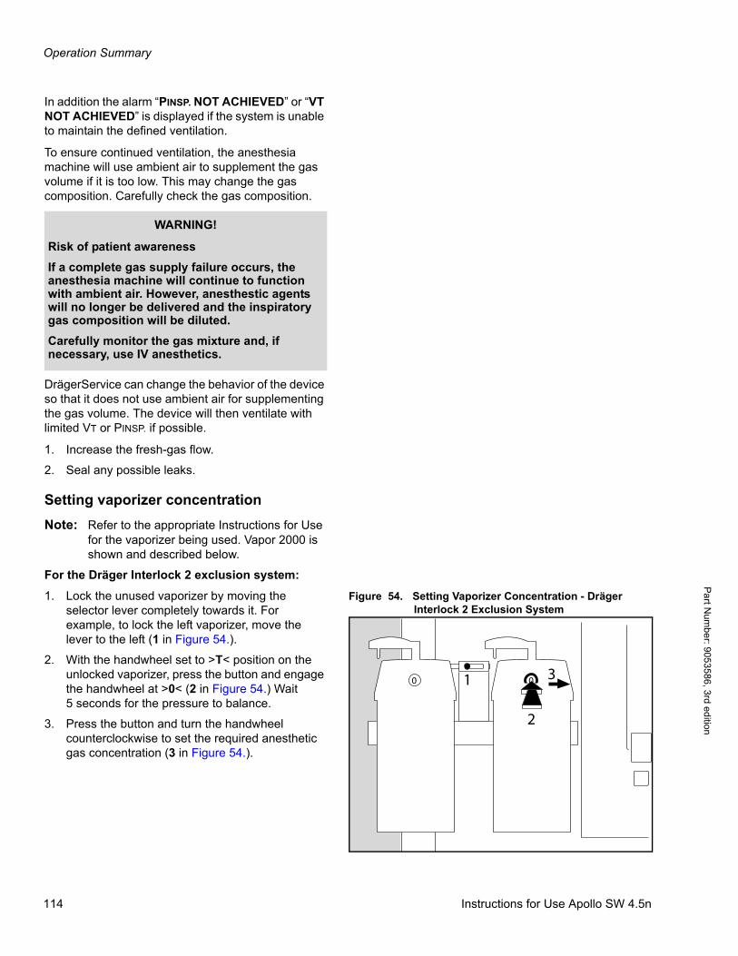
Operation Summary
Pa
rt Num
ber: 905358
6, 3rd edition
In addition the alarm “PINSP. NOT ACHIEVED” or “VT NOT ACHIEVED” is displayed if the system is unable to maintain the defined ventilation.
To ensure continued ventilation, the anesthesia machine will use ambient air to supplement the gas volume if it is too low. This may change the gas composition. Carefully check the gas composition.
DrägerService can change the behavior of the device so that it does not use ambient air for supplementing the gas volume. The device will then ventilate with limited VT or PINSP. if possible.
1. Increase the fresh-gas flow.
2. Seal any possible leaks.
Setting vaporizer concentration
Note: Refer to the appropriate Instructions for Use for the vaporizer being used. Vapor 2000 is shown and described below.
For the Dräger Interlock 2 exclusion system:
Figure 54. Setting Vaporizer Concentration - Dräger Interlock 2 Exclusion System
1. Lock the unused vaporizer by moving the selector lever completely towards it. For example, to lock the left vaporizer, move the lever to the left (1 in Figure 54.).
2. With the handwheel set to >T< position on the unlocked vaporizer, press the button and engage the handwheel at >0< (2 in Figure 54.) Wait 5 seconds for the pressure to balance.
3. Press the button and turn the handwheel counterclockwise to set the required anesthetic gas concentration (3 in Figure 54.).
WARNING!
Risk of patient awareness
If a complete gas supply failure occurs, the anesthesia machine will continue to function with ambient air. However, anesthestic agents will no longer be delivered and the inspiratory gas composition will be diluted.
Carefully monitor the gas mixture and, if necessary, use IV anesthetics.
10 0
2
3
114 Instructions for Use Apollo SW 4.5n
Operation Summary
Par
t Num
ber:
905
3586
, 3rd
edi
tion
For the Dräger Auto Exclusion system:
1. Close any open vaporizers.
2. With the handwheel set to >T< position, press the button and engage the handwheel at >0<. Wait 5 seconds for the pressure to balance.
3. Press the button and turn the handwheel counterclockwise to set the required anesthetic gas concentration.
Setting ventilation mode
Set the ventilation mode as described in the chapter “Ventilation”.
Changing patientsFollow the steps below for successive patient cases.
Switch to standby mode
1. Press the standby key > <, and confirm with
the rotary knob.
The functions of the anesthesia machine are switched off. All the current settings from the previous case are retained, including fresh-gas delivery and ventilation parameters, alarm limits, and patient age and weight.
To activate the default settings instead of using the current settings:
1. Press the >Restore Default Settings< key on the standby screen, and press the rotary knob.
The default settings for gas delivery, ventilation, and alarm limits are restored.
Enter the new patient’s age and ideal body weight (optional) as instructed on page 112, and proceed.
WARNING!
Risk of patient injury
Restored default settings may contain settings inappropriate for a new patient.
After default settings have been restored, make sure the ventilation monitoring settings are appropriate to the patient connected.
Instructions for Use Apollo SW 4.5n 115

Operation Summary
Pa
rt Num
ber: 905358
6, 3rd edition
Changing soda limeIn Standby Conf., see “Configuring the default settings in Standby” on page 201 , the maximum number of use days can be set for the absorber based on clinical hygiene guidelines. Use days monitoring is then available on the Check List, during the Self Test and on the Self Test Results page (“Self test results” on page 102).
A reusable absorber or the disposable CLIC absorber can be used with the Apollo. The soda lime must be exchanged, if:
– the soda lime in the absorber has turned violet. The color indicator can regenerate slowly and the soda lime may revert to white, but its absorption capacity is nevertheless spent. You should therefore dispose of used absorbers immediately.
– the fractional inspiratory CO2 concentration FiCO2 exceeds 5 mmHg.
Information on when the soda lime has been changed will be logged in the system when the automatic test is started.
Reusable absorber
1. Press the standby key > <, and confirm with
the rotary knob.
2. Swing the writing tray out of the way.
3. Press the release button on the ventilator unit, and pull out the unit.
4. Turn the absorber canister counterclockwise and pull it down and off.
5. Empty the used soda lime and refer to the Instructions for Use of the soda lime for waste removal and refilling.
6. Fill the absorber canister to upper mark with fresh soda lime.
7. Fit the canister into position below the breathing system, and turn it clockwise as far as possible.
8. Push the breathing system inwards until it clicks into place.
9. Reset the absorbent change log to current date by pressing the >soda lime changed< button.
116 Instructions for Use Apollo SW 4.5n
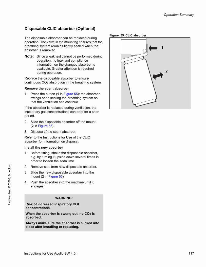
Operation Summary
Par
t Num
ber:
905
3586
, 3rd
edi
tion
Disposable CLIC absorber (Optional)
Figure 55. CLIC absorberThe disposable absorber can be replaced during operation. The valve in the mounting ensures that the breathing system remains tightly sealed when the absorber is removed.
Note: Since a leak test cannot be performed during operation, no leak and compliance information on the changed absorber is available. Greater attention is required during operation.
Replace the disposable absorber to ensure continuous CO2 absorption in the breathing system.
Remove the spent absorber
1. Press the button (1 in Figure 55): the absorber swings open sealing the breathing system so that the ventilation can continue.
If the absorber is replaced during ventilation, the inspiratory gas concentrations can drop for a short period.
2. Slide the disposable absorber off the mount(2 in Figure 55).
3. Dispose of the spent absorber.
Refer to the Instructions for Use of the CLIC absorber for information on disposal.
Install the new absorber
1. Before fitting, shake the disposable absorber, e.g. by turning it upside down several times in order to loosen the soda lime.
2. Remove seal from new disposable absorber.
3. Slide the new disposable absorber into the mount (2 in Figure 55)
4. Push the absorber into the machine until it engages.
1
2
WARNING!
Risk of increased inspiratory CO2 concentrations
When the absorber is swung out, no CO2 is absorbed.
Always make sure the absorber is clicked into place after installing or replacing.
Instructions for Use Apollo SW 4.5n 117
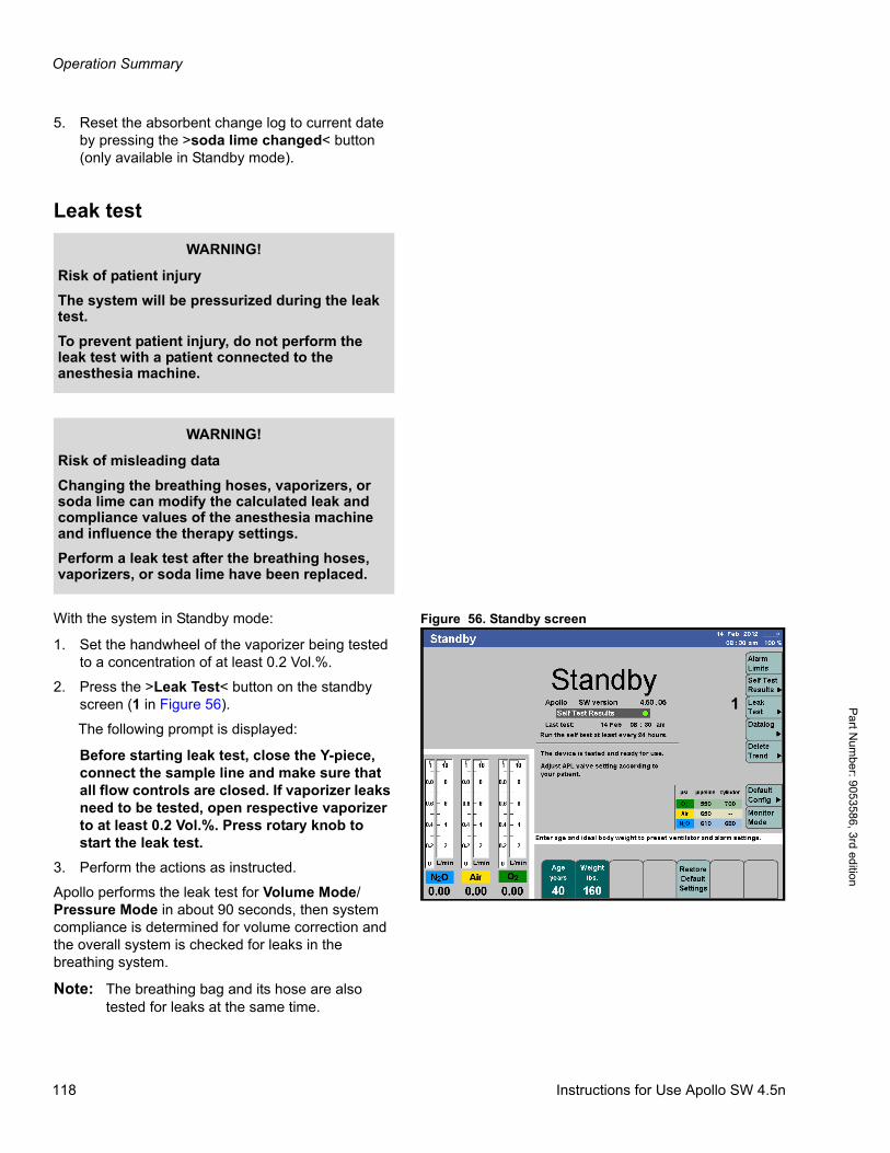
Operation Summary
Pa
rt Num
ber: 905358
6, 3rd edition
5. Reset the absorbent change log to current date by pressing the >soda lime changed< button (only available in Standby mode).
Leak test
Figure 56. Standby screenWith the system in Standby mode:
1. Set the handwheel of the vaporizer being tested to a concentration of at least 0.2 Vol.%.
2. Press the >Leak Test< button on the standby screen (1 in Figure 56).
The following prompt is displayed:
Before starting leak test, close the Y-piece, connect the sample line and make sure that all flow controls are closed. If vaporizer leaks need to be tested, open respective vaporizer to at least 0.2 Vol.%. Press rotary knob to start the leak test.
3. Perform the actions as instructed.
Apollo performs the leak test for Volume Mode/Pressure Mode in about 90 seconds, then system compliance is determined for volume correction and the overall system is checked for leaks in the breathing system.
Note: The breathing bag and its hose are also tested for leaks at the same time.
WARNING!
Risk of patient injury
The system will be pressurized during the leak test.
To prevent patient injury, do not perform the leak test with a patient connected to the anesthesia machine.
WARNING!
Risk of misleading data
Changing the breathing hoses, vaporizers, or soda lime can modify the calculated leak and compliance values of the anesthesia machine and influence the therapy settings.
Perform a leak test after the breathing hoses, vaporizers, or soda lime have been replaced.
1
118 Instructions for Use Apollo SW 4.5n
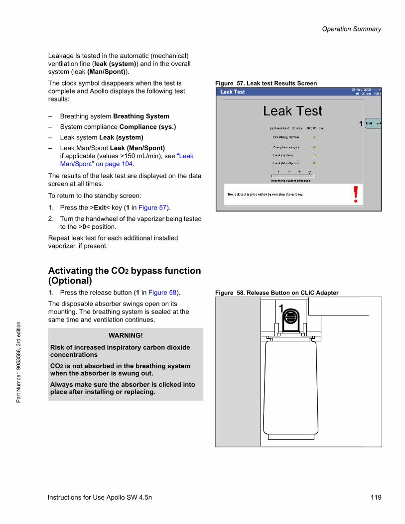
Operation Summary
Par
t Num
ber:
905
3586
, 3rd
edi
tion
Leakage is tested in the automatic (mechanical) ventilation line (leak (system)) and in the overall system (leak (Man/Spont)).
Figure 57. Leak test Results ScreenThe clock symbol disappears when the test is complete and Apollo displays the following test results:
The results of the leak test are displayed on the data screen at all times.
To return to the standby screen:
1. Press the >Exit< key (1 in Figure 57).
2. Turn the handwheel of the vaporizer being tested to the >0< position.
Repeat leak test for each additional installed vaporizer, if present.
Activating the CO2 bypass function (Optional)
Figure 58. Release Button on CLIC Adapter1. Press the release button (1 in Figure 58).
The disposable absorber swings open on its mounting. The breathing system is sealed at the same time and ventilation continues.
1– Breathing system Breathing System
– System compliance Compliance (sys.)
– Leak system Leak (system)
– Leak Man/Spont Leak (Man/Spont)if applicable (values >150 mL/min), see “Leak Man/Spont” on page 104.
1
WARNING!
Risk of increased inspiratory carbon dioxide concentrations
CO2 is not absorbed in the breathing system when the absorber is swung out.
Always make sure the absorber is clicked into place after installing or replacing.
Instructions for Use Apollo SW 4.5n 119
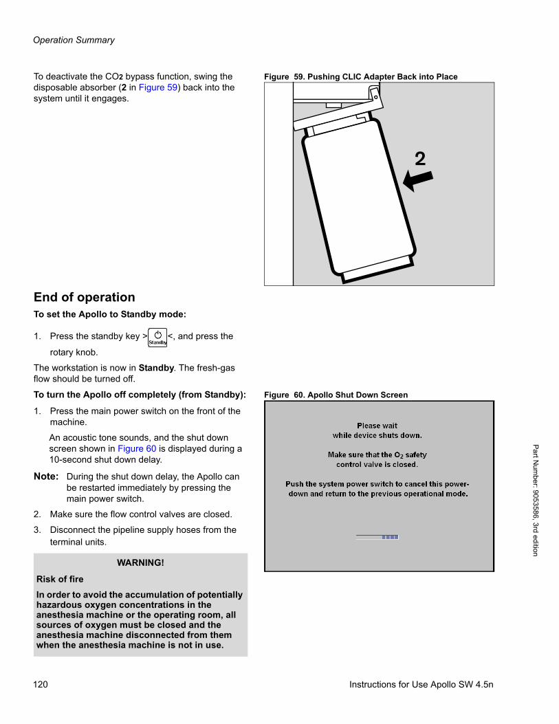
Operation Summary
Pa
rt Num
ber: 905358
6, 3rd edition
Figure 59. Pushing CLIC Adapter Back into PlaceTo deactivate the CO2 bypass function, swing the disposable absorber (2 in Figure 59) back into the system until it engages.
End of operationTo set the Apollo to Standby mode:
1. Press the standby key > <, and press the
rotary knob.
The workstation is now in Standby. The fresh-gas flow should be turned off.
Figure 60. Apollo Shut Down ScreenTo turn the Apollo off completely (from Standby):
1. Press the main power switch on the front of the machine.
An acoustic tone sounds, and the shut down screen shown in Figure 60 is displayed during a 10-second shut down delay.
Note: During the shut down delay, the Apollo can be restarted immediately by pressing the main power switch.
2. Make sure the flow control valves are closed.
3. Disconnect the pipeline supply hoses from the terminal units.
2
WARNING!
Risk of fire
In order to avoid the accumulation of potentially hazardous oxygen concentrations in the anesthesia machine or the operating room, all sources of oxygen must be closed and the anesthesia machine disconnected from them when the anesthesia machine is not in use.
120 Instructions for Use Apollo SW 4.5n
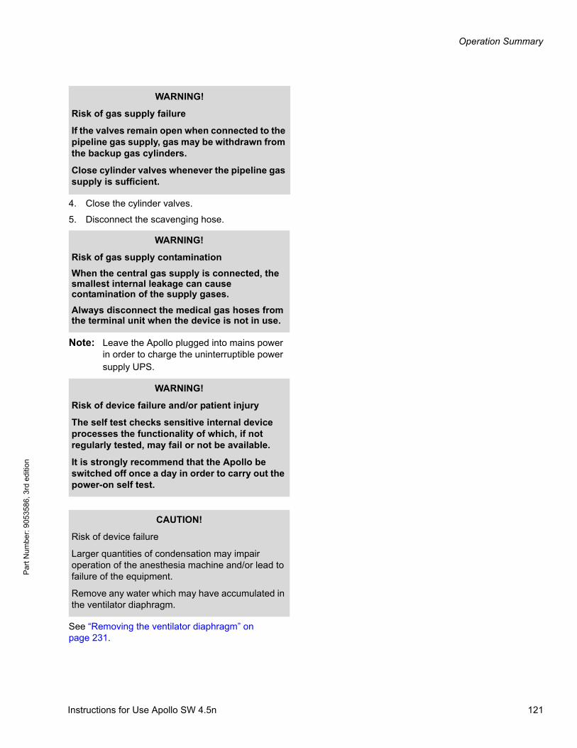
Operation Summary
Par
t Num
ber:
905
3586
, 3rd
edi
tion
4. Close the cylinder valves.
5. Disconnect the scavenging hose.
Note: Leave the Apollo plugged into mains power in order to charge the uninterruptible power supply UPS.
See “Removing the ventilator diaphragm” on page 231.
WARNING!
Risk of gas supply failure
If the valves remain open when connected to the pipeline gas supply, gas may be withdrawn from the backup gas cylinders.
Close cylinder valves whenever the pipeline gas supply is sufficient.
WARNING!
Risk of gas supply contamination
When the central gas supply is connected, the smallest internal leakage can cause contamination of the supply gases.
Always disconnect the medical gas hoses from the terminal unit when the device is not in use.
WARNING!
Risk of device failure and/or patient injury
The self test checks sensitive internal device processes the functionality of which, if not regularly tested, may fail or not be available.
It is strongly recommend that the Apollo be switched off once a day in order to carry out the power-on self test.
CAUTION!
Risk of device failure
Larger quantities of condensation may impair operation of the anesthesia machine and/or lead to failure of the equipment.
Remove any water which may have accumulated in the ventilator diaphragm.
Instructions for Use Apollo SW 4.5n 121
Operation Summary
Pa
rt Num
ber: 905358
6, 3rd edition
When Apollo is not in use
Observe the following if the Apollo is not used for an extended period of time:
1. Unplug the gas pipeline hoses from the wall pipeline supply.
2. Close the cylinder valves on the backup gas cylinders.
3. Leave the anesthesia machine connected to the mains at all times. The green LED labeled >N AC Power< lights up.
WARNING!
Risk of battery failure
Allowing the battery to run low can damage it.
It must be charged at least every four weeks.
122 Instructions for Use Apollo SW 4.5n
Ventilation
Par
t Num
ber:
905
3586
, 3rd
edi
tion
Ventilation
ContentsOverview . . . . . . . . . . . . . . . . . . . . . . . . . . . . . . . . . . . . . . . . . . . . . . . . . . . . . . . . . . . . . . . . . . . . . . . . . . . . . . 125
Manual/Spontaneous ventilation . . . . . . . . . . . . . . . . . . . . . . . . . . . . . . . . . . . . . . . . . . . . . . . . . . . . . . . . . . . 126
Setting the APL valve . . . . . . . . . . . . . . . . . . . . . . . . . . . . . . . . . . . . . . . . . . . . . . . . . . . . . . . . . . . . . . . . . . . . . 126
For manual ventilation . . . . . . . . . . . . . . . . . . . . . . . . . . . . . . . . . . . . . . . . . . . . . . . . . . . . . . . . . . . . . . . . . 126
For spontaneous breathing . . . . . . . . . . . . . . . . . . . . . . . . . . . . . . . . . . . . . . . . . . . . . . . . . . . . . . . . . . . . . 126
Starting Manual/Spontaneous Ventilation . . . . . . . . . . . . . . . . . . . . . . . . . . . . . . . . . . . . . . . . . . . . . . . . . . . . . . 127
Presetting the Manual/Spontaneous mode . . . . . . . . . . . . . . . . . . . . . . . . . . . . . . . . . . . . . . . . . . . . . . . . . 127
Starting the Manual/Spontaneous mode . . . . . . . . . . . . . . . . . . . . . . . . . . . . . . . . . . . . . . . . . . . . . . . . . . . 127
O2 flush . . . . . . . . . . . . . . . . . . . . . . . . . . . . . . . . . . . . . . . . . . . . . . . . . . . . . . . . . . . . . . . . . . . . . . . . . . . . . . . . 128
Volume-Controlled Ventilation . . . . . . . . . . . . . . . . . . . . . . . . . . . . . . . . . . . . . . . . . . . . . . . . . . . . . . . . . . . . 129
Compliance compensation . . . . . . . . . . . . . . . . . . . . . . . . . . . . . . . . . . . . . . . . . . . . . . . . . . . . . . . . . . . . . . . . . 129
Starting volume-controlled ventilation . . . . . . . . . . . . . . . . . . . . . . . . . . . . . . . . . . . . . . . . . . . . . . . . . . . . . . . . . 129
Presetting the volume-controlled ventilation mode . . . . . . . . . . . . . . . . . . . . . . . . . . . . . . . . . . . . . . . . . . . 129
Starting the volume-controlled ventilation mode . . . . . . . . . . . . . . . . . . . . . . . . . . . . . . . . . . . . . . . . . . . . . 130
Synchronized volume-controlled ventilation . . . . . . . . . . . . . . . . . . . . . . . . . . . . . . . . . . . . . . . . . . . . . . . . . . . . 131
Synchronized volume-controlled ventilation with Pressure Support (Optional) . . . . . . . . . . . . . . . . . . . . . . . . . 132
Volume Mode AutoFlow - Volume AF (Optional) . . . . . . . . . . . . . . . . . . . . . . . . . . . . . . . . . . . . . . . . . . . . . . 133
Starting Volume Mode AutoFlow . . . . . . . . . . . . . . . . . . . . . . . . . . . . . . . . . . . . . . . . . . . . . . . . . . . . . . . . . . . . 134
Presetting the Volume AutoFlow ventilation mode . . . . . . . . . . . . . . . . . . . . . . . . . . . . . . . . . . . . . . . . . . . . 134
Starting the Volume AutoFlow ventilation mode . . . . . . . . . . . . . . . . . . . . . . . . . . . . . . . . . . . . . . . . . . . . . . 135
Synchronized volume-guaranteed ventilation . . . . . . . . . . . . . . . . . . . . . . . . . . . . . . . . . . . . . . . . . . . . . . . . . . . 136
Synchronized volume-guaranteed ventilation with Pressure Support (Optional) . . . . . . . . . . . . . . . . . . . . . . . . 137
Pressure-Controlled Ventilation . . . . . . . . . . . . . . . . . . . . . . . . . . . . . . . . . . . . . . . . . . . . . . . . . . . . . . . . . . . 138
Starting Pressure-Controlled Ventilation . . . . . . . . . . . . . . . . . . . . . . . . . . . . . . . . . . . . . . . . . . . . . . . . . . . . . . . 138
Presetting the pressure-controlled ventilation mode . . . . . . . . . . . . . . . . . . . . . . . . . . . . . . . . . . . . . . . . . . 138
Starting the pressure-controlled ventilation mode . . . . . . . . . . . . . . . . . . . . . . . . . . . . . . . . . . . . . . . . . . . . 139
Synchronized pressure-controlled ventilation . . . . . . . . . . . . . . . . . . . . . . . . . . . . . . . . . . . . . . . . . . . . . . . . . . . 140
Synchronized pressure-controlled ventilation with Pressure Support (Optional) . . . . . . . . . . . . . . . . . . . . . . . . 141
Pressure Support Ventilation (Optional) . . . . . . . . . . . . . . . . . . . . . . . . . . . . . . . . . . . . . . . . . . . . . . . . . . . . 142
Starting Pressure Support Ventilation . . . . . . . . . . . . . . . . . . . . . . . . . . . . . . . . . . . . . . . . . . . . . . . . . . . . . . . . . 143
Presetting the Pressure Support ventilation mode . . . . . . . . . . . . . . . . . . . . . . . . . . . . . . . . . . . . . . . . . . . . 143
Starting the Pressure Support ventilation mode . . . . . . . . . . . . . . . . . . . . . . . . . . . . . . . . . . . . . . . . . . . . . . 143
Continuous Positive Airway Pressure CPAP - in Pressure Support Mode (Optional) . . . . . . . . . . . . . . . . 145
Changing between ventilation modes . . . . . . . . . . . . . . . . . . . . . . . . . . . . . . . . . . . . . . . . . . . . . . . . . . . . . . 146
Instructions for Use Apollo SW 4.5n 123
Ventilation
Part N
umber: 90
53586, 3rd edition
Automatic parameter changes . . . . . . . . . . . . . . . . . . . . . . . . . . . . . . . . . . . . . . . . . . . . . . . . . . . . . . . . . . . . . 147
TINSP changes . . . . . . . . . . . . . . . . . . . . . . . . . . . . . . . . . . . . . . . . . . . . . . . . . . . . . . . . . . . . . . . . . . . . . . . . . . 147
Frequency changes . . . . . . . . . . . . . . . . . . . . . . . . . . . . . . . . . . . . . . . . . . . . . . . . . . . . . . . . . . . . . . . . . . . . . . . 147
PEEP changes . . . . . . . . . . . . . . . . . . . . . . . . . . . . . . . . . . . . . . . . . . . . . . . . . . . . . . . . . . . . . . . . . . . . . . . . . . 148
Auxiliary common gas outlet (Aux CGO) ventilation (Optional) . . . . . . . . . . . . . . . . . . . . . . . . . . . . . . . . . . 148
Diverting fresh gas to the auxiliary CGO . . . . . . . . . . . . . . . . . . . . . . . . . . . . . . . . . . . . . . . . . . . . . . . . . . . . . . . 149
Presetting the auxiliary CGO monitoring . . . . . . . . . . . . . . . . . . . . . . . . . . . . . . . . . . . . . . . . . . . . . . . . . . . 149
Starting the auxiliary CGO monitoring . . . . . . . . . . . . . . . . . . . . . . . . . . . . . . . . . . . . . . . . . . . . . . . . . . . . . 150
Ending the auxiliary CGO ventilation . . . . . . . . . . . . . . . . . . . . . . . . . . . . . . . . . . . . . . . . . . . . . . . . . . . . . . 151
124 Instructions for Use Apollo SW 4.5n

Ventilation
Par
t Num
ber:
905
3586
, 3rd
edi
tion
OverviewThe Apollo supports the following ventilation modes:
– Manual/Spontaneous ventilation Man/Spont
– Volume-controlled ventilation Volume Mode.With activation of:
– Sync. (Synchronization)
– Press. Support (Pressure Support) (optional)
– Pressure-controlled ventilation Pressure Mode.With activation of:
– Sync. (Synchronization)
– Press. Support (Pressure Support) (optional)
– Pressure-assisted spontaneous breathing Pressure Support CPAP (optional)
– Volume AF (Volume Mode AutoFlow) (optional).With activation of:
– Sync. (Synchronization)
– Press. Support (Pressure Support) (optional).
In addition, the optional auxiliary common gas outlet (Aux CGO) is available for use of non-rebreathing systems.
This chapter contains descriptions of these modes, along with complete instructions for setting the corresponding ventilation parameters.
CAUTION!
Risk of inadequate alarm monitoring
Some Alarm limits may be automatically modified when the ventilation is changed or the settings are modified.
Check or adapt alarm limits each time the ventilation mode is changed or when the settings are modified while a patient is being ventilated.
Instructions for Use Apollo SW 4.5n 125
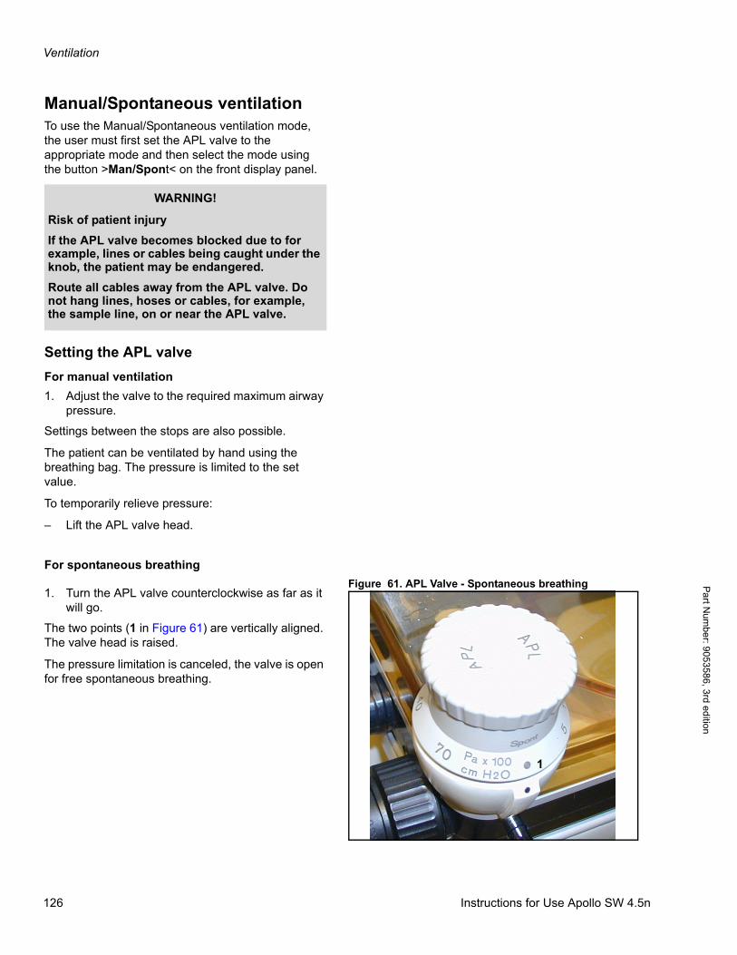
Ventilation
Pa
rt Num
ber: 905358
6, 3rd edition
Manual/Spontaneous ventilationTo use the Manual/Spontaneous ventilation mode, the user must first set the APL valve to the appropriate mode and then select the mode using the button >Man/Spont< on the front display panel.
Setting the APL valve
For manual ventilation
1. Adjust the valve to the required maximum airway pressure.
Settings between the stops are also possible.
The patient can be ventilated by hand using the breathing bag. The pressure is limited to the set value.
To temporarily relieve pressure:
– Lift the APL valve head.
For spontaneous breathing
Figure 61. APL Valve - Spontaneous breathing 1. Turn the APL valve counterclockwise as far as it
will go.
The two points (1 in Figure 61) are vertically aligned. The valve head is raised.
The pressure limitation is canceled, the valve is open for free spontaneous breathing.
WARNING!
Risk of patient injury
If the APL valve becomes blocked due to for example, lines or cables being caught under the knob, the patient may be endangered.
Route all cables away from the APL valve. Do not hang lines, hoses or cables, for example, the sample line, on or near the APL valve.
1
126 Instructions for Use Apollo SW 4.5n

Ventilation
Par
t Num
ber:
905
3586
, 3rd
edi
tion
Starting Manual/Spontaneous Ventilation
Presetting the Manual/Spontaneous mode
Figure 62. Man/Spont ScreenPrior to activating Man/Spont mode, the user can preset the Man/Spont parameters.
1. Press the >Man Spont< key located at the bottom of the display panel (1 in Figure 62). The LED on the key and the status field at the top of the screen (2 in Figure 62) flash on and off.
The row of buttons for the ventilation parameters valid for ManSpont mode are displayed light green (4 in Figure 62). This means that they are not yet active.
2. Press the button for the parameter to be changed; its color changes to yellow to indicate that it’s selected.
3. Turn the rotary knob to adjust the parameter to the desired value, and press the rotary knob to confirm (3 in Figure 62).
Continue to set the values for the other parameters.
The parameters that can be set for ManSpont mode are shown in Table 3, along with their adjustment ranges and factory default values.
The patient’s ideal body weight is the actual weight minus estimated excess fat.
Starting the Manual/Spontaneous mode
Table 3 . Adjustment ranges and factory settings for Man/Spont mode
4. When all the Man/Spont parameters have been preset, press the rotary knob to start Man/Spont ventilation (3 in Figure 62).
The parameter buttons turn dark green and display the preset parameter values. The “Man/Spont” indication in the status field stops flashing and is displayed continuously. Manual/Spontaneous ventilation begins.
5. Set an appropriate fresh-gas flow. Verify adequate flow by checking the total flow meter.
If a Man/Spont parameter has to be changed during ventilation:
– Press the button for the parameter to be changed, turn the rotary knob to the desired value, and press the rotary knob to confirm.
Vol. AFMode
1
4
2
3
Ventilation parameters
Adjustment ranges
Factory
settings1)
1) Site defaults can be set instead.
Age>Age<[years]
<1 to 120 40
Ideal body weight>Weight<2)
[kg/lbs.]
2) Optional
1 to 120 kg,1 to 240 lbs.
--
Instructions for Use Apollo SW 4.5n 127
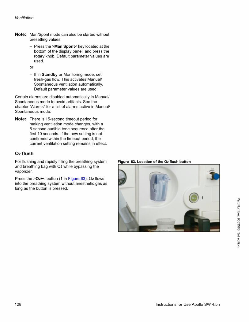
Ventilation
Pa
rt Num
ber: 905358
6, 3rd edition
Note: Man/Spont mode can also be started without presetting values:
– Press the >Man Spont< key located at the bottom of the display panel, and press the rotary knob. Default parameter values are used.
or
– If in Standby or Monitoring mode, set fresh-gas flow. This activates Manual/Spontaneous ventilation automatically. Default parameter values are used.
Certain alarms are disabled automatically in Manual/Spontaneous mode to avoid artifacts. See the chapter “Alarms” for a list of alarms active in Manual/Spontaneous mode.
Note: There is 15-second timeout period for making ventilation mode changes, with a 5-second audible tone sequence after the first 10 seconds. If the new setting is not confirmed within the timeout period, the current ventilation setting remains in effect.
O2 flush
Figure 63. Location of the O2 flush buttonFor flushing and rapidly filling the breathing system and breathing bag with O2 while bypassing the vaporizer.
Press the >O2+< button (1 in Figure 63). O2 flows into the breathing system without anesthetic gas as long as the button is pressed.
1
128 Instructions for Use Apollo SW 4.5n
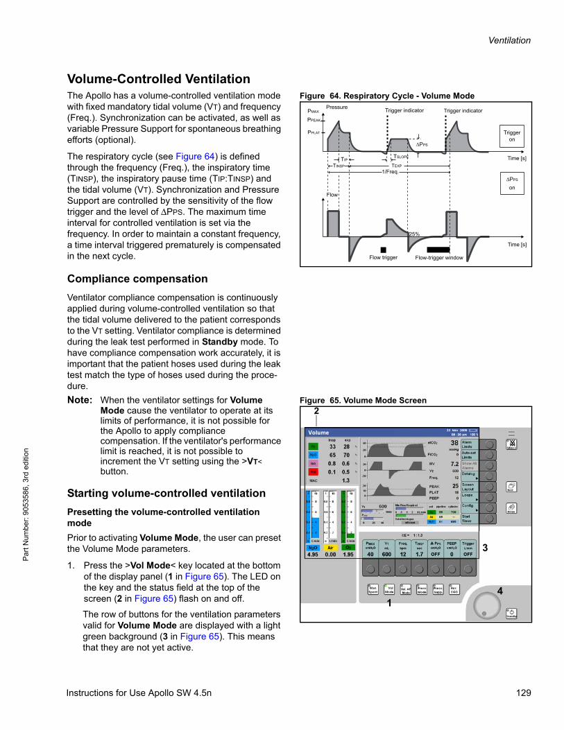
Ventilation
Par
t Num
ber:
905
3586
, 3rd
edi
tion
Volume-Controlled VentilationFigure 64. Respiratory Cycle - Volume ModeThe Apollo has a volume-controlled ventilation mode
with fixed mandatory tidal volume (VT) and frequency (Freq.). Synchronization can be activated, as well as variable Pressure Support for spontaneous breathing efforts (optional).
The respiratory cycle (see Figure 64) is defined through the frequency (Freq.), the inspiratory time (TINSP), the inspiratory pause time (TIP:TINSP) and the tidal volume (VT). Synchronization and Pressure Support are controlled by the sensitivity of the flow trigger and the level of ΔPPS. The maximum time interval for controlled ventilation is set via the frequency. In order to maintain a constant frequency, a time interval triggered prematurely is compensated in the next cycle.
Compliance compensation
Ventilator compliance compensation is continuously applied during volume-controlled ventilation so that the tidal volume delivered to the patient corresponds to the VT setting. Ventilator compliance is determined during the leak test performed in Standby mode. To have compliance compensation work accurately, it is important that the patient hoses used during the leak test match the type of hoses used during the proce-dure.
Figure 65. Volume Mode ScreenNote: When the ventilator settings for Volume Mode cause the ventilator to operate at its limits of performance, it is not possible for the Apollo to apply compliance compensation. If the ventilator's performance limit is reached, it is not possible to increment the VT setting using the >VT< button.
Starting volume-controlled ventilation
Presetting the volume-controlled ventilation mode
Prior to activating Volume Mode, the user can preset the Volume Mode parameters.
1. Press the >Vol Mode< key located at the bottom of the display panel (1 in Figure 65). The LED on the key and the status field at the top of the screen (2 in Figure 65) flash on and off.
The row of buttons for the ventilation parameters valid for Volume Mode are displayed with a light green background (3 in Figure 65). This means that they are not yet active.
Pressure
Time [s]
Flow
TINSP TEXP
Time [s]
1/Freq.
PMAX
PPEAK
PPLAT
TIP
Triggeron
Trigger indicator
PPS
on
Flow-trigger window
Trigger indicator
TSLOPE
PPS
Flow trigger
25%
Vol. AFMode
1
3
4
2
Instructions for Use Apollo SW 4.5n 129
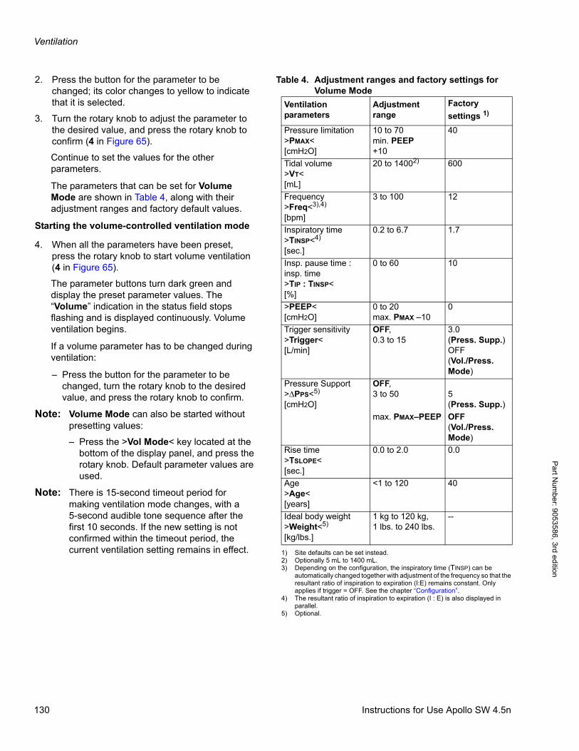
Ventilation
Pa
rt Num
ber: 905358
6, 3rd edition
Table 4. Adjustment ranges and factory settings for Volume Mode
2. Press the button for the parameter to be changed; its color changes to yellow to indicate that it is selected.
3. Turn the rotary knob to adjust the parameter to the desired value, and press the rotary knob to confirm (4 in Figure 65).
Continue to set the values for the other parameters.
The parameters that can be set for Volume Mode are shown in Table 4, along with their adjustment ranges and factory default values.
Starting the volume-controlled ventilation mode
4. When all the parameters have been preset, press the rotary knob to start volume ventilation (4 in Figure 65).
The parameter buttons turn dark green and display the preset parameter values. The “Volume” indication in the status field stops flashing and is displayed continuously. Volume ventilation begins.
If a volume parameter has to be changed during ventilation:
– Press the button for the parameter to be changed, turn the rotary knob to the desired value, and press the rotary knob to confirm.
Note: Volume Mode can also be started without presetting values:
– Press the >Vol Mode< key located at the bottom of the display panel, and press the rotary knob. Default parameter values are used.
Note: There is 15-second timeout period for making ventilation mode changes, with a 5-second audible tone sequence after the first 10 seconds. If the new setting is not confirmed within the timeout period, the current ventilation setting remains in effect.
Ventilation parameters
Adjustment range
Factory
settings 1)
1) Site defaults can be set instead.
Pressure limitation>PMAX<[cmH2O]
10 to 70min. PEEP+10
40
Tidal volume>VT<[mL]
20 to 14002)
2) Optionally 5 mL to 1400 mL.
600
Frequency>Freq<3),4)
[bpm]
3) Depending on the configuration, the inspiratory time (TINSP) can be automatically changed together with adjustment of the frequency so that the resultant ratio of inspiration to expiration (I:E) remains constant. Only applies if trigger = OFF. See the chapter “Configuration”.
3 to 100 12
Inspiratory time>TINSP<4)
[sec.]
4) The resultant ratio of inspiration to expiration (I : E) is also displayed in parallel.
0.2 to 6.7 1.7
Insp. pause time : insp. time>TIP : TINSP<[%]
0 to 60 10
>PEEP<[cmH2O]
0 to 20 max. PMAX –10
0
Trigger sensitivity>Trigger<[L/min]
OFF,0.3 to 15
3.0(Press. Supp.)OFF(Vol./Press. Mode)
Pressure Support>ΔPPS<5)
[cmH2O]
5) Optional.
OFF,3 to 50 5
(Press. Supp.)
max. PMAX–PEEP OFF(Vol./Press. Mode)
Rise time>TSLOPE<[sec.]
0.0 to 2.0 0.0
Age>Age<[years]
<1 to 120 40
Ideal body weight>Weight<5)
[kg/lbs.]
1 kg to 120 kg,1 lbs. to 240 lbs.
--
130 Instructions for Use Apollo SW 4.5n
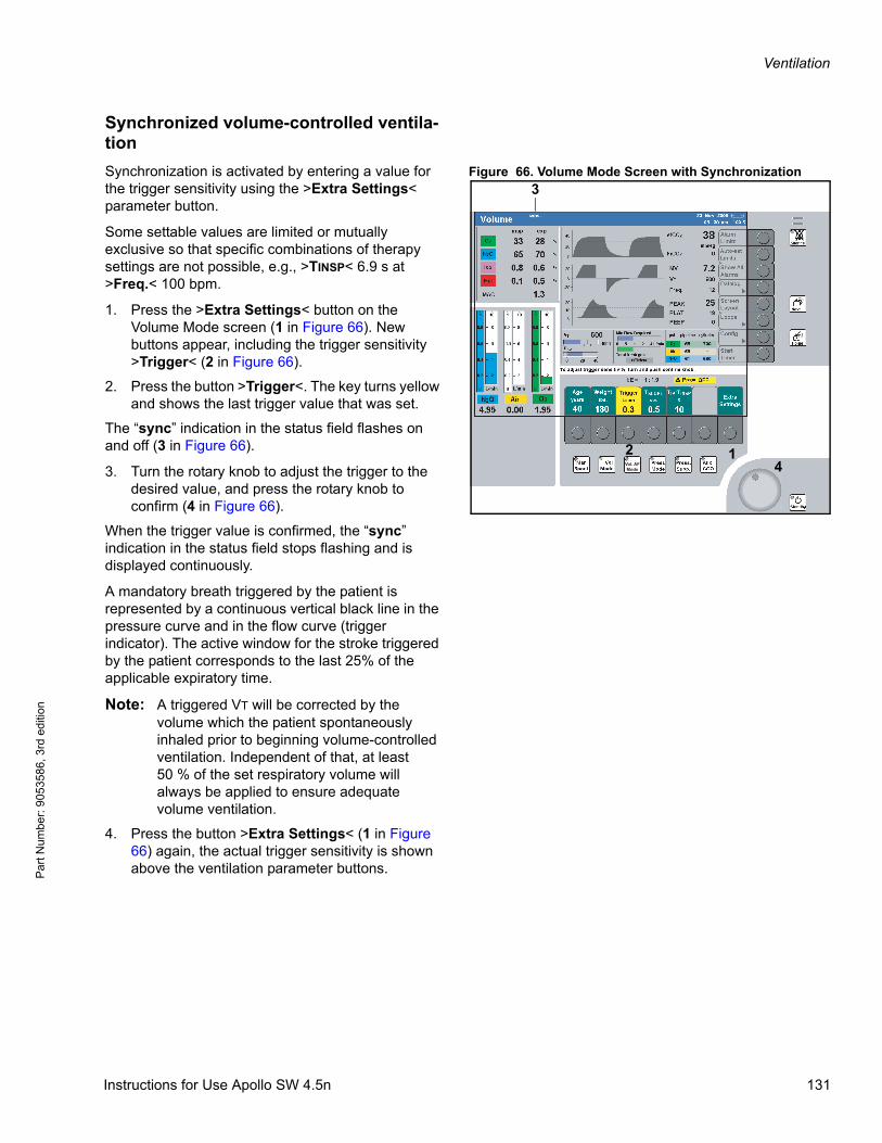
Ventilation
Par
t Num
ber:
905
3586
, 3rd
edi
tion
Synchronized volume-controlled ventila-tion
Figure 66. Volume Mode Screen with SynchronizationSynchronization is activated by entering a value for the trigger sensitivity using the >Extra Settings< parameter button.
Some settable values are limited or mutually exclusive so that specific combinations of therapy settings are not possible, e.g., >TINSP< 6.9 s at >Freq.< 100 bpm.
1. Press the >Extra Settings< button on the Volume Mode screen (1 in Figure 66). New buttons appear, including the trigger sensitivity >Trigger< (2 in Figure 66).
2. Press the button >Trigger<. The key turns yellow and shows the last trigger value that was set.
The “sync” indication in the status field flashes on and off (3 in Figure 66).
3. Turn the rotary knob to adjust the trigger to the desired value, and press the rotary knob to confirm (4 in Figure 66).
When the trigger value is confirmed, the “sync” indication in the status field stops flashing and is displayed continuously.
A mandatory breath triggered by the patient is represented by a continuous vertical black line in the pressure curve and in the flow curve (trigger indicator). The active window for the stroke triggered by the patient corresponds to the last 25% of the applicable expiratory time.
Note: A triggered VT will be corrected by the volume which the patient spontaneously inhaled prior to beginning volume-controlled ventilation. Independent of that, at least 50 % of the set respiratory volume will always be applied to ensure adequate volume ventilation.
4. Press the button >Extra Settings< (1 in Figure 66) again, the actual trigger sensitivity is shown above the ventilation parameter buttons.
Vol. AFMode
12
3
4
Instructions for Use Apollo SW 4.5n 131
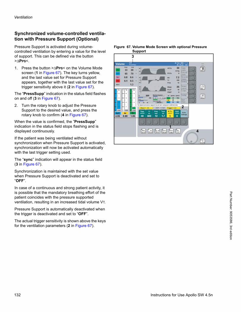
Ventilation
Pa
rt Num
ber: 905358
6, 3rd edition
Synchronized volume-controlled ventila-tion with Pressure Support (Optional)
Figure 67. Volume Mode Screen with optional Pressure Support
Pressure Support is activated during volume-controlled ventilation by entering a value for the level of support. This can be defined via the button >ΔPPS<.
1. Press the button >ΔPPS< on the Volume Mode screen (1 in Figure 67). The key turns yellow, and the last value set for Pressure Support appears, together with the last value set for the trigger sensitivity above it (2 in Figure 67).
The “PressSupp” indication in the status field flashes on and off (3 in Figure 67).
2. Turn the rotary knob to adjust the Pressure Support to the desired value, and press the rotary knob to confirm (4 in Figure 67).
When the value is confirmed, the ”PressSupp” indication in the status field stops flashing and is displayed continuously.
If the patient was being ventilated without synchronization when Pressure Support is activated, synchronization will now be activated automatically with the last trigger setting used.
The “sync” indication will appear in the status field(3 in Figure 67).
Synchronization is maintained with the set value when Pressure Support is deactivated and set to “OFF”.
In case of a continuous and strong patient activity, it is possible that the mandatory breathing effort of the patient coincides with the pressure supported ventilation, resulting in an increased tidal volume VT.
Pressure Support is automatically deactivated when the trigger is deactivated and set to “OFF”.
The actual trigger sensitivity is shown above the keys for the ventilation parameters (2 in Figure 67).
Vol. AFMode
1
2
4
3
132 Instructions for Use Apollo SW 4.5n
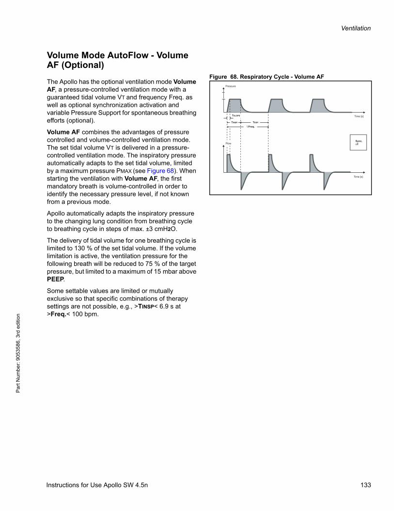
Ventilation
Par
t Num
ber:
905
3586
, 3rd
edi
tion
Volume Mode AutoFlow - Volume AF (Optional)
Figure 68. Respiratory Cycle - Volume AFThe Apollo has the optional ventilation mode Volume AF, a pressure-controlled ventilation mode with a guaranteed tidal volume VT and frequency Freq. as well as optional synchronization activation and variable Pressure Support for spontaneous breathing efforts (optional).
Volume AF combines the advantages of pressure controlled and volume-controlled ventilation mode. The set tidal volume VT is delivered in a pressure-controlled ventilation mode. The inspiratory pressure automatically adapts to the set tidal volume, limited by a maximum pressure PMAX (see Figure 68). When starting the ventilation with Volume AF, the first mandatory breath is volume-controlled in order to identify the necessary pressure level, if not known from a previous mode.
Apollo automatically adapts the inspiratory pressure to the changing lung condition from breathing cycle to breathing cycle in steps of max. ±3 cmH2O.
The delivery of tidal volume for one breathing cycle is limited to 130 % of the set tidal volume. If the volume limitation is active, the ventilation pressure for the following breath will be reduced to 75 % of the target pressure, but limited to a maximum of 15 mbar above PEEP.
Some settable values are limited or mutually exclusive so that specific combinations of therapy settings are not possible, e.g., >TINSP< 6.9 s at >Freq.< 100 bpm.
Pressure
Time [s]
Time [s]
Sync.off
TSLOPE
TINSP. TEXP.
1/Freq.
Flow
Instructions for Use Apollo SW 4.5n 133

Ventilation
Pa
rt Num
ber: 905358
6, 3rd edition
Starting Volume Mode AutoFlow
Presetting the Volume AutoFlow ventilation mode
Figure 69. Volume AF ScreenPrior to activating Volume AF, the user can preset the Volume AF parameters.
1. Press the >Vol. AF Mode< key located at the bottom of the display panel (1 in Figure 69). The LED on the key and the status field at the top of the screen (2 in Figure 69) flash on and off.
The row of buttons for the ventilation parameters valid for Volume AF are displayed with a light green background (3 in Figure 69). This means that they are not yet active.
2. Press the button for the parameter to be changed; its color changes to yellow to indicate that it is selected.
3. Turn the rotary knob to adjust the parameter to the desired value, and press the rotary knob to confirm (4 in Figure 69).
Continue to set the values for the other parameters.
Vol. AFMode 4
1
2
3
134 Instructions for Use Apollo SW 4.5n
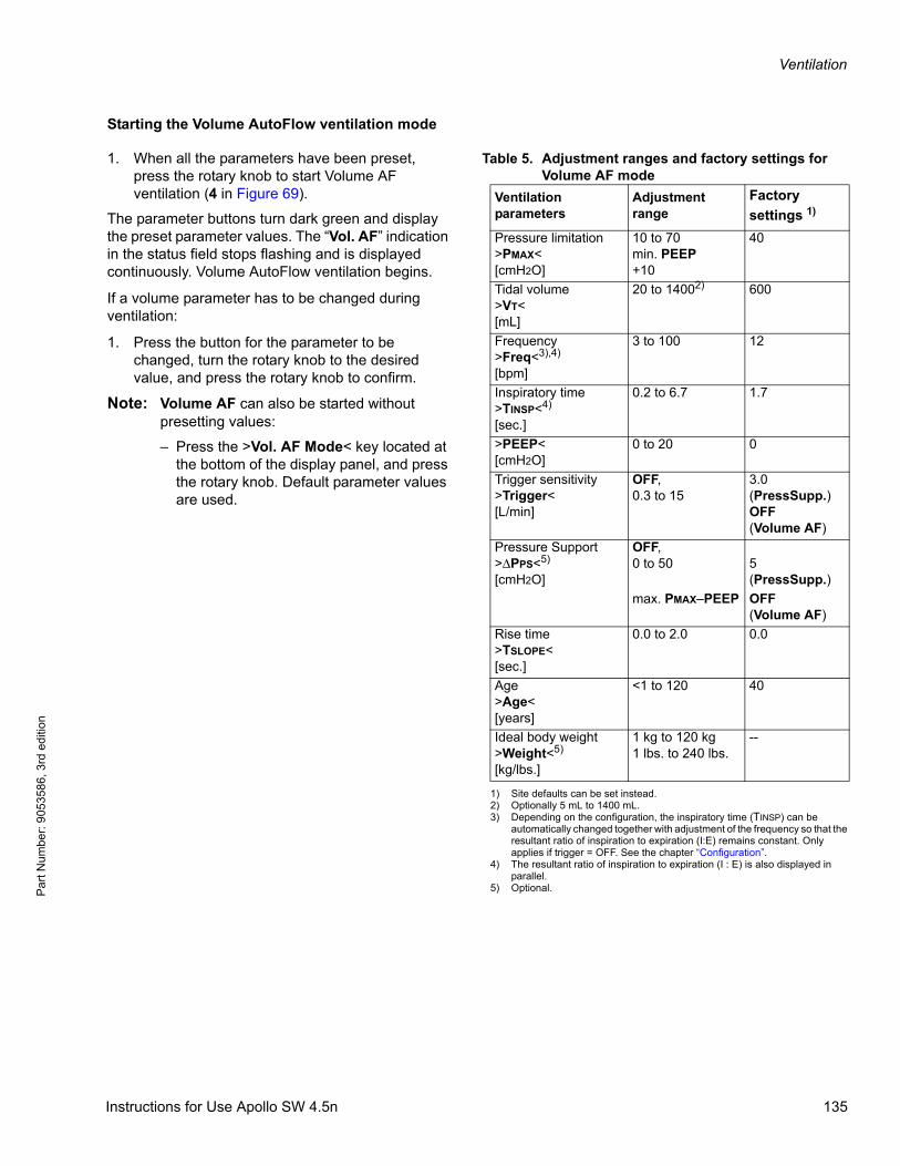
Ventilation
Par
t Num
ber:
905
3586
, 3rd
edi
tion
Starting the Volume AutoFlow ventilation mode
Table 5. Adjustment ranges and factory settings for Volume AF mode
1. When all the parameters have been preset, press the rotary knob to start Volume AF ventilation (4 in Figure 69).
The parameter buttons turn dark green and display the preset parameter values. The “Vol. AF” indication in the status field stops flashing and is displayed continuously. Volume AutoFlow ventilation begins.
If a volume parameter has to be changed during ventilation:
1. Press the button for the parameter to be changed, turn the rotary knob to the desired value, and press the rotary knob to confirm.
Note: Volume AF can also be started without presetting values:
– Press the >Vol. AF Mode< key located at the bottom of the display panel, and press the rotary knob. Default parameter values are used.
Ventilation parameters
Adjustment range
Factory
settings 1)
1) Site defaults can be set instead.
Pressure limitation>PMAX<[cmH2O]
10 to 70min. PEEP+10
40
Tidal volume>VT<[mL]
20 to 14002)
2) Optionally 5 mL to 1400 mL.
600
Frequency>Freq<3),4)
[bpm]
3) Depending on the configuration, the inspiratory time (TINSP) can be automatically changed together with adjustment of the frequency so that the resultant ratio of inspiration to expiration (I:E) remains constant. Only applies if trigger = OFF. See the chapter “Configuration”.
3 to 100 12
Inspiratory time>TINSP<4)
[sec.]
4) The resultant ratio of inspiration to expiration (I : E) is also displayed in parallel.
0.2 to 6.7 1.7
>PEEP<[cmH2O]
0 to 20 0
Trigger sensitivity>Trigger<[L/min]
OFF,0.3 to 15
3.0(PressSupp.)OFF(Volume AF)
Pressure Support>ΔPPS<5)
[cmH2O]
5) Optional.
OFF,0 to 50 5
(PressSupp.)
max. PMAX–PEEP OFF(Volume AF)
Rise time>TSLOPE<[sec.]
0.0 to 2.0 0.0
Age>Age<[years]
<1 to 120 40
Ideal body weight>Weight<5)
[kg/lbs.]
1 kg to 120 kg1 lbs. to 240 lbs.
--
Instructions for Use Apollo SW 4.5n 135
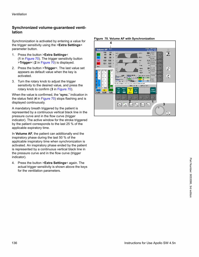
Ventilation
Pa
rt Num
ber: 905358
6, 3rd edition
Synchronized volume-guaranteed venti-lation
Figure 70. Volume AF with SynchronizationSynchronization is activated by entering a value for the trigger sensitivity using the >Extra Settings< parameter button.
1. Press the button >Extra Settings<(1 in Figure 70). The trigger sensitivity button >Trigger< (2 in Figure 70) is displayed.
2. Press the button >Trigger<. The last value set appears as default value when the key is activated.
3. Turn the rotary knob to adjust the trigger sensitivity to the desired value, and press the rotary knob to confirm (3 in Figure 70).
When the value is confirmed, the “sync.” indication in the status field (4 in Figure 70) stops flashing and is displayed continuously.
A mandatory breath triggered by the patient is represented by a continuous vertical black line in the pressure curve and in the flow curve (trigger indicator). The active window for the stroke triggered by the patient corresponds to the last 25 % of the applicable expiratory time.
In Volume AF, the patient can additionally end the inspiratory phase during the last 50 % of the applicable inspiratory time when synchronization is activated. An inspiratory phase ended by the patient is represented by a continuous vertical black line in the pressure curve and in the flow curve (trigger indicator).
4. Press the button >Extra Settings< again. The actual trigger sensitivity is shown above the keys for the ventilation parameters.
Vol. AFMode
12
4
3
136 Instructions for Use Apollo SW 4.5n
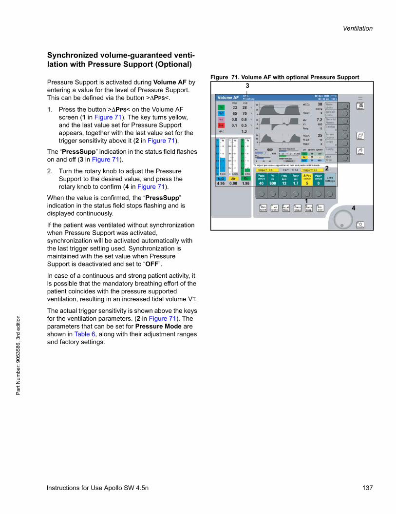
Ventilation
Par
t Num
ber:
905
3586
, 3rd
edi
tion
Synchronized volume-guaranteed venti-lation with Pressure Support (Optional)
Figure 71. Volume AF with optional Pressure SupportPressure Support is activated during Volume AF by entering a value for the level of Pressure Support. This can be defined via the button >ΔPPS<.
1. Press the button >ΔPPS< on the Volume AF screen (1 in Figure 71). The key turns yellow, and the last value set for Pressure Support appears, together with the last value set for the trigger sensitivity above it (2 in Figure 71).
The “PressSupp” indication in the status field flashes on and off (3 in Figure 71).
2. Turn the rotary knob to adjust the Pressure Support to the desired value, and press the rotary knob to confirm (4 in Figure 71).
When the value is confirmed, the “PressSupp” indication in the status field stops flashing and is displayed continuously.
If the patient was ventilated without synchronization when Pressure Support was activated, synchronization will be activated automatically with the last trigger setting used. Synchronization is maintained with the set value when Pressure Support is deactivated and set to “OFF”.
In case of a continuous and strong patient activity, it is possible that the mandatory breathing effort of the patient coincides with the pressure supported ventilation, resulting in an increased tidal volume VT.
The actual trigger sensitivity is shown above the keys for the ventilation parameters. (2 in Figure 71). The parameters that can be set for Pressure Mode are shown in Table 6, along with their adjustment ranges and factory settings.
Vol. AFMode 4
1
3
2
Instructions for Use Apollo SW 4.5n 137
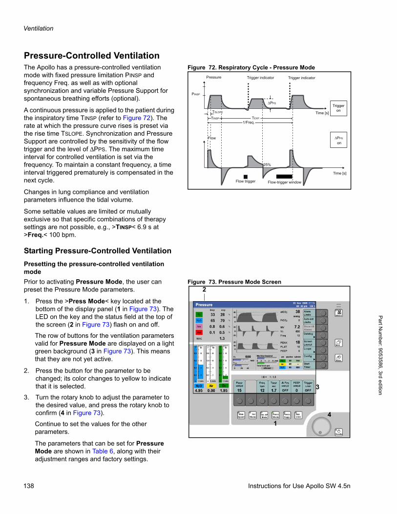
Ventilation
Pa
rt Num
ber: 905358
6, 3rd edition
Pressure-Controlled VentilationFigure 72. Respiratory Cycle - Pressure ModeThe Apollo has a pressure-controlled ventilation
mode with fixed pressure limitation PINSP and frequency Freq. as well as with optional synchronization and variable Pressure Support for spontaneous breathing efforts (optional).
A continuous pressure is applied to the patient during the inspiratory time TINSP (refer to Figure 72). The rate at which the pressure curve rises is preset via the rise time TSLOPE. Synchronization and Pressure Support are controlled by the sensitivity of the flow trigger and the level of ΔPPS. The maximum time interval for controlled ventilation is set via the frequency. To maintain a constant frequency, a time interval triggered prematurely is compensated in the next cycle.
Changes in lung compliance and ventilation parameters influence the tidal volume.
Some settable values are limited or mutually exclusive so that specific combinations of therapy settings are not possible, e.g., >TINSP< 6.9 s at >Freq.< 100 bpm.
Starting Pressure-Controlled Ventilation
Presetting the pressure-controlled ventilation mode
Figure 73. Pressure Mode ScreenPrior to activating Pressure Mode, the user can preset the Pressure Mode parameters.
1. Press the >Press Mode< key located at the bottom of the display panel (1 in Figure 73). The LED on the key and the status field at the top of the screen (2 in Figure 73) flash on and off.
The row of buttons for the ventilation parameters valid for Pressure Mode are displayed on a light green background (3 in Figure 73). This means that they are not yet active.
2. Press the button for the parameter to be changed; its color changes to yellow to indicate that it is selected.
3. Turn the rotary knob to adjust the parameter to the desired value, and press the rotary knob to confirm (4 in Figure 73).
Continue to set the values for the other parameters.
The parameters that can be set for Pressure Mode are shown in Table 6, along with their adjustment ranges and factory settings.
Pressure
Time [s]
Flow
TINSP TEXP
Time [s]
1/Freq.
PINSP
Triggeron
Trigger indicator
on
Flow-trigger windowFlow trigger
Trigger indicator
25%
TSLOPE
Vol. AFMode
1
2
3
4
138 Instructions for Use Apollo SW 4.5n
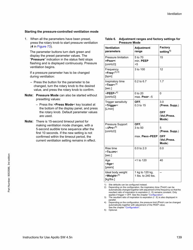
Ventilation
Par
t Num
ber:
905
3586
, 3rd
edi
tion
Starting the pressure-controlled ventilation mode
Table 6. Adjustment ranges and factory settings for Pressure Mode
1. When all the parameters have been preset, press the rotary knob to start pressure ventilation (4 in Figure 73).
The parameter buttons turn dark green and display the preset parameter values. The “Pressure” indication in the status field stops flashing and is displayed continuously. Pressure ventilation begins.
If a pressure parameter has to be changed during ventilation:
– Press the button for the parameter to be changed, turn the rotary knob to the desired value, and press the rotary knob to confirm.
Note: Pressure Mode can also be started without presetting values:
– Press the >Press Mode< key located at the bottom of the display panel, and press the rotary knob. Default parameter values are used.
Note: There is 15-second timeout period for making ventilation mode changes, with a5-second audible tone sequence after the first 10 seconds. If the new setting is not confirmed within the timeout period, the current ventilation setting remains in effect.
Ventilation parameters
Adjustment range
Factory
setting1)
1) Site defaults can be configured instead.
Pressure limitation>PINSP<[cmH2O]
5 to 70min. PEEP+5
15
Frequency>Freq<2),3)
[bpm]
2) Depending on the configuration, the inspiratory time (TINSP) can be automatically changed together with adjustment of the frequency so that the resultant ratio of inspiration to expiration (I : E) remains constant. Only applies if trigger = OFF. See the chapter “Configuration”.
3 to 100 12
Inspiratory time>TINSP<3)
[sec.]
3) The resultant ratio of inspiration to expiration (I : E) is also displayed in parallel.
0.2 to 6.7 1.7
>PEEP<4)
[cmH2O]
4) Depending on the configuration, the pressure limit (PINSP) can be changed automatically together with adjustment of the PEEP value.See the chapter “Configuration”.
0 to 20max. PINSP –5
0
Trigger sensitivity>Trigger<[L/min]
OFF,0.3 to 15
3.0(Press. Supp.)
OFF(Vol./Press. Mode)
Pressure Support>ΔPPS<5)
[cmH2O]
5) Optional.
OFF,3 to 50 5
(Press. Supp.)
max. PMAX–PEEP OFF(Vol./Press. Mode)
Rise time>TSLOPE<[sec.]
0.0 to 2.0 0.0
Age>Age<[years]
<1 to 120 40
Ideal body weight>Weight<5)
[kg/lbs.]
1 kg to 120 kg,1 lbs. to 240 lbs.
--
Instructions for Use Apollo SW 4.5n 139
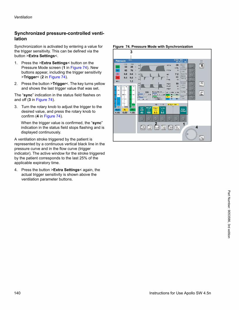
Ventilation
Pa
rt Num
ber: 905358
6, 3rd edition
Synchronized pressure-controlled venti-lation
Figure 74. Pressure Mode with SynchronizationSynchronization is activated by entering a value for the trigger sensitivity. This can be defined via the button >Extra Settings<.
1. Press the >Extra Settings< button on the Pressure Mode screen (1 in Figure 74). New buttons appear, including the trigger sensitivity >Trigger< (2 in Figure 74).
2. Press the button >Trigger<. The key turns yellow and shows the last trigger value that was set.
The “sync” indication in the status field flashes on and off (3 in Figure 74).
3. Turn the rotary knob to adjust the trigger to the desired value, and press the rotary knob to confirm (4 in Figure 74).
When the trigger value is confirmed, the “sync” indication in the status field stops flashing and is displayed continuously.
A ventilation stroke triggered by the patient is represented by a continuous vertical black line in the pressure curve and in the flow curve (trigger indicator). The active window for the stroke triggered by the patient corresponds to the last 25% of the applicable expiratory time.
4. Press the button >Extra Settings< again, the actual trigger sensitivity is shown above the ventilation parameter buttons.
Vol. AFMode
12
3
4
140 Instructions for Use Apollo SW 4.5n
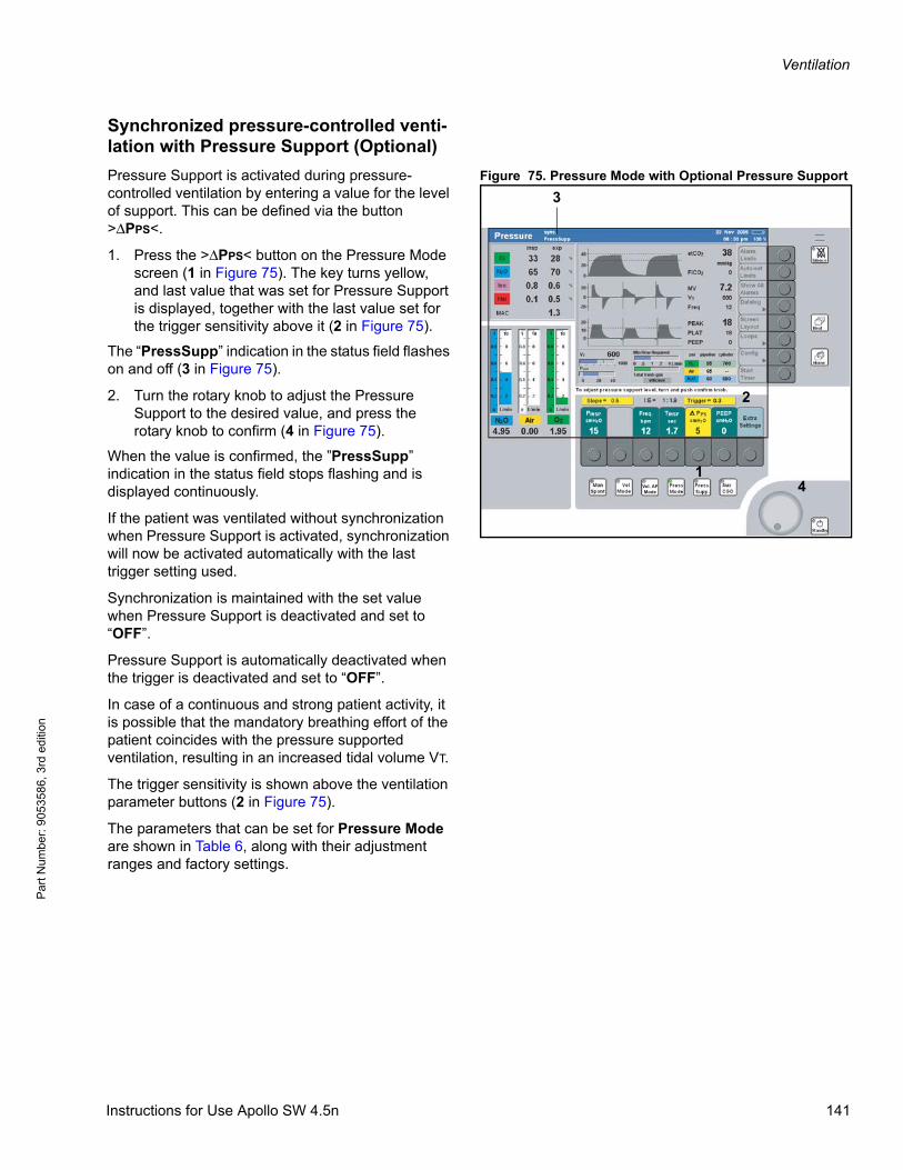
Ventilation
Par
t Num
ber:
905
3586
, 3rd
edi
tion
Synchronized pressure-controlled venti-lation with Pressure Support (Optional)
Figure 75. Pressure Mode with Optional Pressure SupportPressure Support is activated during pressure-controlled ventilation by entering a value for the level of support. This can be defined via the button >ΔPPS<.
1. Press the >ΔPPS< button on the Pressure Mode screen (1 in Figure 75). The key turns yellow, and last value that was set for Pressure Support is displayed, together with the last value set for the trigger sensitivity above it (2 in Figure 75).
The “PressSupp” indication in the status field flashes on and off (3 in Figure 75).
2. Turn the rotary knob to adjust the Pressure Support to the desired value, and press the rotary knob to confirm (4 in Figure 75).
When the value is confirmed, the ”PressSupp” indication in the status field stops flashing and is displayed continuously.
If the patient was ventilated without synchronization when Pressure Support is activated, synchronization will now be activated automatically with the last trigger setting used.
Synchronization is maintained with the set value when Pressure Support is deactivated and set to “OFF”.
Pressure Support is automatically deactivated when the trigger is deactivated and set to “OFF”.
In case of a continuous and strong patient activity, it is possible that the mandatory breathing effort of the patient coincides with the pressure supported ventilation, resulting in an increased tidal volume VT.
The trigger sensitivity is shown above the ventilation parameter buttons (2 in Figure 75).
The parameters that can be set for Pressure Mode are shown in Table 6, along with their adjustment ranges and factory settings.
Vol. AFMode
1
2
3
4
Instructions for Use Apollo SW 4.5n 141

Ventilation
Pa
rt Num
ber: 905358
6, 3rd edition
Pressure Support Ventilation (Optional)
Figure 76. Respiratory Cycle - Pressure Support ModeThe Apollo has a pressure-assisted ventilation mode for patients with spontaneous breathing. Synchronization and Pressure Support for the spontaneous breathing efforts are controlled by the sensitivity of the flow trigger and by the level of ΔPPS.
The rate at which the pressure curve rises is preset by the rise time TSLOPE. Refer to Figure 76.
The maximum inspiratory time for a spontaneous breathing stroke varies according to age: 1.5 seconds for patients aged 4 years and younger, and 4 seconds for patients over 4 years.
Inspiration is ended as soon as the current inspiration flow drops below 25 % of the inspiratory peak flow. Any leakage is compensated simultaneously with the actual airway pressure.
Apnea ventilation can additionally be set with the minimum frequency FreqMIN. The ventilator is automatically triggered by FreqMIN if there is no spontaneous breathing activity by the patient.
This is not a mandatory ventilation stroke by the ventilator; the patient can end the stroke triggered by the ventilator at any time by breathing spontaneously. This stroke is not identified by a trigger indicator.
Apnea ventilation can also be deactivated again by setting the FreqMIN to “OFF”.
Pressure
Time [s]
Flow
TSLOPE
Time [s]
1/Freq.MIN
Trigger indicator
PPS
Trigger indicator
Apnea ventilation
Flow trigger Flow trigger No trigger
25% 25%
1/Freq.MIN
142 Instructions for Use Apollo SW 4.5n
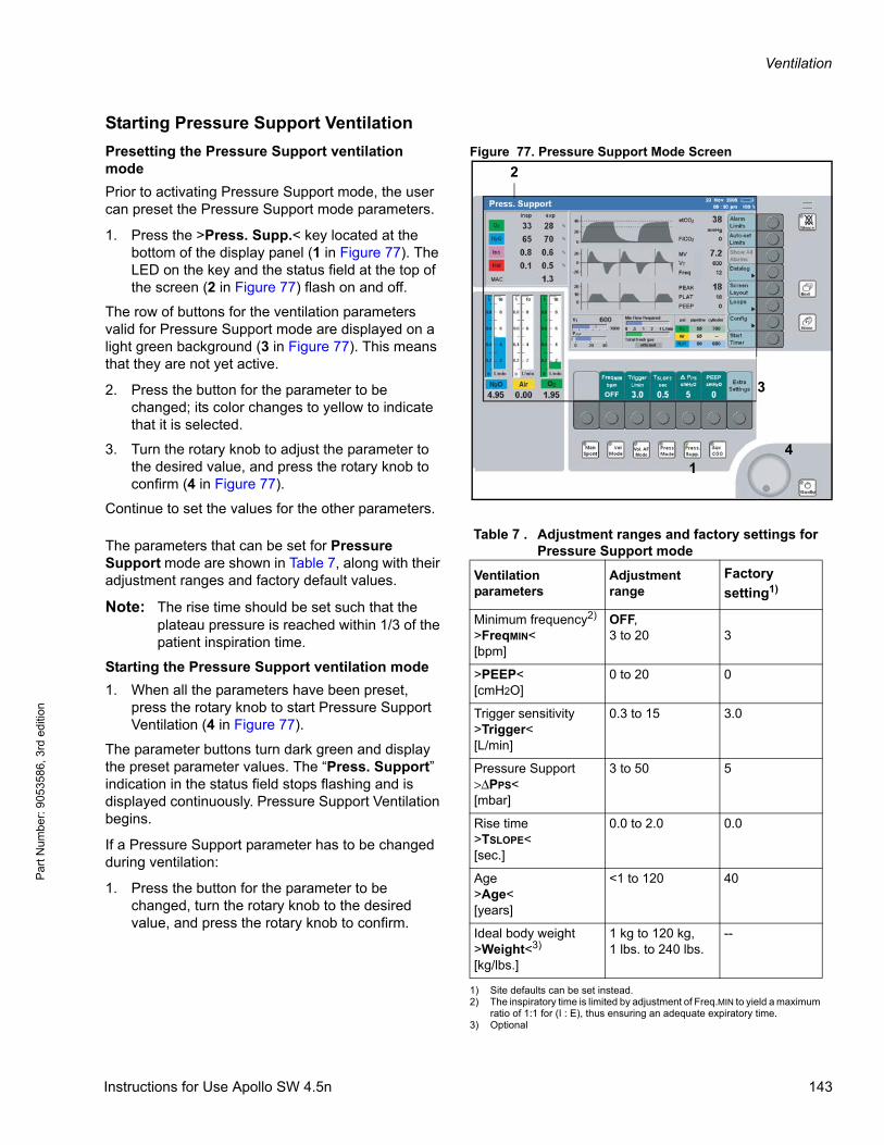
Ventilation
Par
t Num
ber:
905
3586
, 3rd
edi
tion
Starting Pressure Support Ventilation
Figure 77. Pressure Support Mode ScreenPresetting the Pressure Support ventilation mode
Prior to activating Pressure Support mode, the user can preset the Pressure Support mode parameters.
1. Press the >Press. Supp.< key located at the bottom of the display panel (1 in Figure 77). The LED on the key and the status field at the top of the screen (2 in Figure 77) flash on and off.
The row of buttons for the ventilation parameters valid for Pressure Support mode are displayed on a light green background (3 in Figure 77). This means that they are not yet active.
2. Press the button for the parameter to be changed; its color changes to yellow to indicate that it is selected.
3. Turn the rotary knob to adjust the parameter to the desired value, and press the rotary knob to confirm (4 in Figure 77).
Continue to set the values for the other parameters.
Table 7 . Adjustment ranges and factory settings for Pressure Support mode The parameters that can be set for Pressure
Support mode are shown in Table 7, along with their adjustment ranges and factory default values.
Note: The rise time should be set such that the plateau pressure is reached within 1/3 of the patient inspiration time.
Starting the Pressure Support ventilation mode
1. When all the parameters have been preset, press the rotary knob to start Pressure Support Ventilation (4 in Figure 77).
The parameter buttons turn dark green and display the preset parameter values. The “Press. Support” indication in the status field stops flashing and is displayed continuously. Pressure Support Ventilation begins.
If a Pressure Support parameter has to be changed during ventilation:
1. Press the button for the parameter to be changed, turn the rotary knob to the desired value, and press the rotary knob to confirm.
Vol. AFMode
1
2
3
4
Ventilation parameters
Adjustment range
Factory
setting1)
1) Site defaults can be set instead.
Minimum frequency2) >FreqMIN<[bpm]
2) The inspiratory time is limited by adjustment of Freq.MIN to yield a maximum ratio of 1:1 for (I : E), thus ensuring an adequate expiratory time.
OFF,3 to 20 3
>PEEP<[cmH2O]
0 to 20 0
Trigger sensitivity>Trigger<[L/min]
0.3 to 15 3.0
Pressure Support>ΔPPS<[mbar]
3 to 50 5
Rise time>TSLOPE<[sec.]
0.0 to 2.0 0.0
Age>Age<[years]
<1 to 120 40
Ideal body weight>Weight<3)
[kg/lbs.]
3) Optional
1 kg to 120 kg,1 lbs. to 240 lbs.
--
Instructions for Use Apollo SW 4.5n 143
Ventilation
Pa
rt Num
ber: 905358
6, 3rd edition
Note: Pressure Support mode can also be started without presetting values:
– Press the >Press. Supp< key located at the bottom of the display panel, and press the rotary knob. Default parameter values are used.
Note: There is 15 second timeout period for making ventilation mode changes, with a5-second audible tone sequence after the first 10 seconds. If the new setting is not confirmed within the timeout period, the current ventilation setting remains in effect.
144 Instructions for Use Apollo SW 4.5n

Ventilation
Par
t Num
ber:
905
3586
, 3rd
edi
tion
Continuous Positive Airway Pres-sure CPAP - in Pressure Support Mode (Optional)The pressure support option on the Apollo is enhanced with Continuous Positive Airway Pressure (CPAP).
CPAP allows the patient to breath spontaneously on an increased pressure level and therefore helps to increase the functional residual capacity. It is indicated for use only in patients who are breathing spontaneously.
Continuous Positive Airway Pressure is activated in Pressure Support when the value for the Pressure Support ΔPPS is set <= 2 cmH2O.
The apnea ventilation is not active during Pressure Support CPAP. When CPAP is activated, the minimum frequency FreqMIN is set to OFF and the rise time is set to 0.0.
Table 8. Adjustment ranges and factory settings for CPAP The parameters that can be set for CPAP mode are
shown in Table 8, along with their adjustment ranges and factory default values. Ventilation
parametersAdjustment range
Factory
setting1)
1) Site defaults can be configured instead.
Minimum frequency>FreqMIN<2)
[bpm]
2) Depending on the configuration, the inspiratory time (TINSP) can be automatically changed together with adjustment of the frequency so that the resultant ratio of inspiration to expiration (I : E) remains constant. Only applies if trigger = OFF. See the chapter “Configuration”.
OFF, 3 to 20
OFF (CPAP)
3
>PEEP<[cmH2O]
0 to 20 0
Trigger sensitivity>Trigger<[L/min]
0.3 to 15 3.0
Pressure Support>ΔPPS<3)
[cmH2O]
3) Optional.
>2 to 50
0 to 2 (CPAP)
5
Rise time>TSLOPE<[sec.]
0.0 to 2.0
0.0 (CPAP)
0.0
Age>Age<[years]
<1 to 120 40
Ideal body weight>Weight<3)
[kg/lbs.]
1 kg to 120 kg,1 lbs. to 240 lbs.
--
Instructions for Use Apollo SW 4.5n 145
Ventilation
Pa
rt Num
ber: 905358
6, 3rd edition
Changing between ventilation modesWhen changing to a different ventilation mode, the presettings are adopted or appropriately derived from the parameters of the preceding mode.
Parameters which are identical in both ventilation modes are adopted directly (e.g. Freq., TINSP, ΔPPS, Trigger).
When changing from volume-controlled to pressure-controlled ventilation modes:
The measured parameter PLAT is adopted as the new value for PINSP. If a valid plateau pressure value is not available, the last value used in the case will be used as the preset value (the preset value of PINSP will be at least PEEP + 5). The PAW LOW alarm limit will be pre-set to PINSP-2 if the alarm limit was higher than PINSP-2 during volume-controlled ventilation.
When changing from pressure-controlled to volume-controlled ventilation modes:
The new tidal volume VT is adopted from the measured minute volume MV and the set frequency Freq. Only the minute volume applied by the ventilator is taken into account. Pressure supported breathing strokes by the patient are disregarded.
When changing from automatic ventilation modes to Pressure Support mode (optional):
The set PEEP, ΔPPS, and Trigger are adopted.
If ΔPPS and/or Trigger were set to “OFF”, the last values used are adopted in Pressure Support mode. In all other cases the configured default settings are used.
The PAW LOW alarm limit will be pre-set to PEEP+ΔPPS-2 if the alarm limit was higher than PEEP+ΔPPS-2 during automatic ventilation mode.
When changing from Pressure Support mode (optional) to automatic ventilation modes:
The set PEEP, ΔPPS, and Trigger values are adopted. The last values that were set are used for the other parameters and the configured default settings in all other cases.
Note: In minimum flow mode, the following secondary effects may occur that affect ventilation of the patient:
– Leakage: Check if the breathing bag is adequately filled.
146 Instructions for Use Apollo SW 4.5n
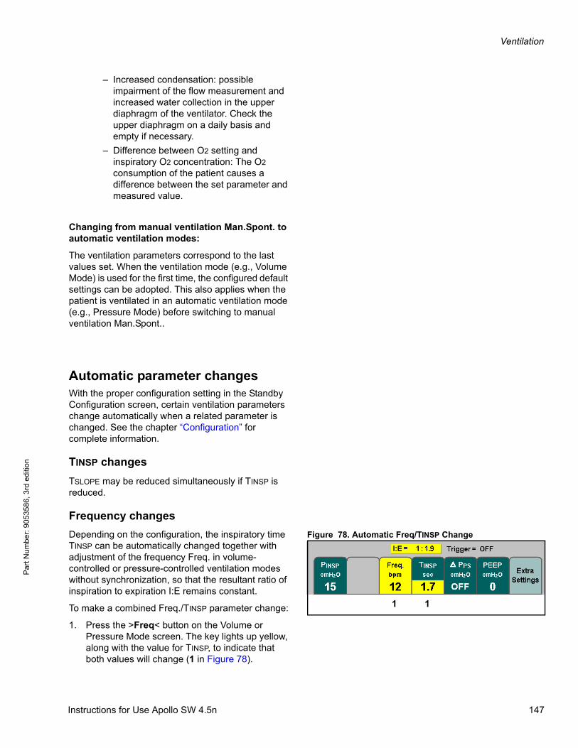
Ventilation
Par
t Num
ber:
905
3586
, 3rd
edi
tion
– Increased condensation: possible impairment of the flow measurement and increased water collection in the upper diaphragm of the ventilator. Check the upper diaphragm on a daily basis and empty if necessary.
– Difference between O2 setting and inspiratory O2 concentration: The O2 consumption of the patient causes a difference between the set parameter and measured value.
Changing from manual ventilation Man.Spont. to automatic ventilation modes:
The ventilation parameters correspond to the last values set. When the ventilation mode (e.g., Volume Mode) is used for the first time, the configured default settings can be adopted. This also applies when the patient is ventilated in an automatic ventilation mode (e.g., Pressure Mode) before switching to manual ventilation Man.Spont..
Automatic parameter changesWith the proper configuration setting in the Standby Configuration screen, certain ventilation parameters change automatically when a related parameter is changed. See the chapter “Configuration” for complete information.
TINSP changes
TSLOPE may be reduced simultaneously if TINSP is reduced.
Frequency changes
Figure 78. Automatic Freq/TINSP ChangeDepending on the configuration, the inspiratory time TINSP can be automatically changed together with adjustment of the frequency Freq. in volume-controlled or pressure-controlled ventilation modes without synchronization, so that the resultant ratio of inspiration to expiration I:E remains constant.
To make a combined Freq./TINSP parameter change:
1. Press the >Freq< button on the Volume or Pressure Mode screen. The key lights up yellow, along with the value for TINSP, to indicate that both values will change (1 in Figure 78).
1 1
Instructions for Use Apollo SW 4.5n 147
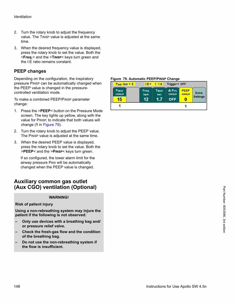
Ventilation
Pa
rt Num
ber: 905358
6, 3rd edition
2. Turn the rotary knob to adjust the frequency value. The TINSP value is adjusted at the same time.
3. When the desired frequency value is displayed, press the rotary knob to set the value. Both the >Freq.< and the >TINSP< keys turn green and the I:E ratio remains constant.
PEEP changes
Figure 79. Automatic PEEP/PINSP ChangeDepending on the configuration, the inspiratory pressure PINSP can be automatically changed when the PEEP value is changed in the pressure-controlled ventilation mode.
To make a combined PEEP/PINSP parameter change:
1. Press the >PEEP< button on the Pressure Mode screen. The key lights up yellow, along with the value for PINSP, to indicate that both values will change (1 in Figure 79).
2. Turn the rotary knob to adjust the PEEP value. The PINSP value is adjusted at the same time.
3. When the desired PEEP value is displayed, press the rotary knob to set the value. Both the >PEEP< and the >PINSP< keys turn green.
If so configured, the lower alarm limit for the airway pressure PAW will be automatically changed when the PEEP value is changed.
Auxiliary common gas outlet (Aux CGO) ventilation (Optional)
1 1
WARNING!
Risk of patient injury
Using a non-rebreathing system may injure the patient if the following is not observed:
– Only use devices with a breathing bag and/or pressure relief valve.
– Check the fresh-gas flow and the condition of the breathing bag.
– Do not use the non-rebreathing system if the flow is insufficient.
148 Instructions for Use Apollo SW 4.5n

Ventilation
Par
t Num
ber:
905
3586
, 3rd
edi
tion
Figure 80. Auxiliary CGO - Bain Circuit shownExample: Bain system
1. Prepare the system according to the corresponding Instructions for Use.
To monitor O2, CO2, and anesthetic gases:
2. Connect the sample line to the Luer lock connection on the mask manifold and to the water trap connection on the front of the Apollo (1 in Figure 80).
For mask manifolds without a sample line connector:
– Place a T-piece with filter between the mask pipe and fresh-gas connection port.
or:
– where applicable, use a Luer lock filter connection.
3. Connect the fresh-gas hose of the Bain system to the auxiliary common gas outlet(2 in Figure 80).
4. To remove exhaled gas, connect the non-rebreathing system connector (3 in Figure 80) to the Y-piece.
5. Follow the Instructions for Use provided with the non-rebreathing system.
Diverting fresh gas to the auxiliary CGO
Figure 81. Auxiliary CGO Ventilation ScreenPresetting the auxiliary CGO monitoring
Prior to activating auxiliary CGO monitoring, the user can preset the auxiliary CGO parameters.
1. Press the >Aux CGO< key located at the bottom of the display panel (1 in Figure 81).
The LED on the key and the status field at the top of the screen (2 in Figure 81) flash on and off.
The buttons for the parameters valid for auxiliary CGO monitoring are displayed on a light green background (4 in Figure 81). This means that they are not yet active.
2. Press the button for the parameter to be changed; its color changes to yellow to indicate that it is selected.
3. Turn the rotary knob to adjust the parameter to the desired value, and press the rotary knob to confirm (3 in Figure 81).
3
2
1
1
Vol. AFMode
1
2
3
4
Instructions for Use Apollo SW 4.5n 149
Ventilation
Pa
rt Num
ber: 905358
6, 3rd edition
Continue to set the values for the other parameter.
The parameters that can be set for auxiliary CGO monitoring are shown in Table 9, along with their adjustment ranges and factory default values.
Note: The patient’s ideal body weight is the actual weight minus estimated excess fat.
Starting the auxiliary CGO monitoring
Table 9 . Adjustment ranges and factory settings for auxiliary CGO monitoring parameters 1. When all the auxiliary CGO monitoring
parameters have been preset, press the rotary knob to start auxiliary CGO monitoring (3 in Figure 81).
The parameter buttons turn green and display the preset parameter values. The “Aux CGO” indication in the status field stops flashing and is displayed continuously. Auxiliary CGO monitoring begins.
2. Set an appropriate fresh-gas flow. The fresh-gas supply must be equal to at least twice the minute volume in order to exclude rebreathing.
If an auxiliary CGO monitoring parameter has to be changed during ventilation:
1. Press the button for the parameter to be changed, turn the rotary knob to the desired value, and press the rotary knob to confirm.
Note: Auxiliary CGO monitoring can also be started without presetting values:
– Press the >Aux CGO< key located at the bottom of the display panel, and press the rotary knob. Default parameter values are used.
Note: There is 15 second timeout period for making ventilation mode changes, with a5-second audible tone sequence after the first 10 seconds. If the new setting is not confirmed within the timeout period, the current ventilation setting remains in effect.
Airway pressure PAW and the mandatory frequency Freq., PPEAK, and PMEAN are measured at the auxiliary common gas outlet.
Pressure measurement may be impaired by activating the O2 flush.
The minute volume MV and tidal volume VT are not measured.
Ventilation parameter(auxiliary CGO monitoring)
Adjustment rangeFactory
setting1)
1) Site defaults can be set instead.
Age>Age<[years]
<1 to 120 40
Ideal body weight>Weight<2)
[kg/lbs.]
2) Optional
1 kg to 120 kg,1 lbs. to 240 lbs.
--
150 Instructions for Use Apollo SW 4.5n
Ventilation
Par
t Num
ber:
905
3586
, 3rd
edi
tion
Certain alarms are disabled automatically in order to avoid artifacts. See the chapter “Alarms” for complete information.
Excess fresh gas can be discharged into the anesthetic gas scavenging line via the breathing system of the Apollo. For this purpose, the non-rebreathing system must be connected to the Y-piece of the breathing hoses connected to the breathing system.
Ending the auxiliary CGO ventilation
1. Press any ventilation mode key, other than >Aux CGO<. The LED of the selected ventilation mode key and the status field flash on and off.
2. Press the rotary knob. The ventilation is switched to the Apollo internal rebreathing system.
Note: When changing back to the Apollo rebreathing system, reconnect the sample line to the Y-piece.
WARNING!
Risk of patient injury
If the bag does not inflate, the patient will not receive adequate ventilation. Switch to the Apollo internal breathing system and ventilate the patient using an automatic ventilation mode.
CAUTION!
Risk of increased ambient gas concentration
Ambient air may become contaminated with anesthetic agent when using non-rebreathing systems.
Ensure sufficient ambient air circulation.
Instructions for Use Apollo SW 4.5n 151

Ventilation
Pa
rt Num
ber: 905358
6, 3rd edition
This page intentionally left blank.
152 Instructions for Use Apollo SW 4.5n
Monitoring
Par
t Num
ber:
905
3586
, 3rd
edi
tion
Monitoring
ContentsOverview . . . . . . . . . . . . . . . . . . . . . . . . . . . . . . . . . . . . . . . . . . . . . . . . . . . . . . . . . . . . . . . . . . . . . . . . . . . . . . 155
Standard screen . . . . . . . . . . . . . . . . . . . . . . . . . . . . . . . . . . . . . . . . . . . . . . . . . . . . . . . . . . . . . . . . . . . . . . . . 155
Screen layout . . . . . . . . . . . . . . . . . . . . . . . . . . . . . . . . . . . . . . . . . . . . . . . . . . . . . . . . . . . . . . . . . . . . . . . . . . 156
Selecting a default layout . . . . . . . . . . . . . . . . . . . . . . . . . . . . . . . . . . . . . . . . . . . . . . . . . . . . . . . . . . . . . . . . . . 156
Modifying current layout . . . . . . . . . . . . . . . . . . . . . . . . . . . . . . . . . . . . . . . . . . . . . . . . . . . . . . . . . . . . . . . . . . . 156
Adjusting display brightness . . . . . . . . . . . . . . . . . . . . . . . . . . . . . . . . . . . . . . . . . . . . . . . . . . . . . . . . . . . . . . . . 157
Displayed parameters . . . . . . . . . . . . . . . . . . . . . . . . . . . . . . . . . . . . . . . . . . . . . . . . . . . . . . . . . . . . . . . . . . . 157
CO2 concentration . . . . . . . . . . . . . . . . . . . . . . . . . . . . . . . . . . . . . . . . . . . . . . . . . . . . . . . . . . . . . . . . . . . . 157
O2 concentration . . . . . . . . . . . . . . . . . . . . . . . . . . . . . . . . . . . . . . . . . . . . . . . . . . . . . . . . . . . . . . . . . . . . . 158
Anesthetic gas . . . . . . . . . . . . . . . . . . . . . . . . . . . . . . . . . . . . . . . . . . . . . . . . . . . . . . . . . . . . . . . . . . . . . . . 158
Airway pressure . . . . . . . . . . . . . . . . . . . . . . . . . . . . . . . . . . . . . . . . . . . . . . . . . . . . . . . . . . . . . . . . . . . . . . 158
Respiratory flow and volume . . . . . . . . . . . . . . . . . . . . . . . . . . . . . . . . . . . . . . . . . . . . . . . . . . . . . . . . . . . . 158
SpO2 concentration (Optional) . . . . . . . . . . . . . . . . . . . . . . . . . . . . . . . . . . . . . . . . . . . . . . . . . . . . . . . . . . . 159
Loops (Optional) . . . . . . . . . . . . . . . . . . . . . . . . . . . . . . . . . . . . . . . . . . . . . . . . . . . . . . . . . . . . . . . . . . . . . . 159
Mini trends (optional) . . . . . . . . . . . . . . . . . . . . . . . . . . . . . . . . . . . . . . . . . . . . . . . . . . . . . . . . . . . . . . . . . . 160
Virtual flow tubes . . . . . . . . . . . . . . . . . . . . . . . . . . . . . . . . . . . . . . . . . . . . . . . . . . . . . . . . . . . . . . . . . . . . . 160
Gas supply module . . . . . . . . . . . . . . . . . . . . . . . . . . . . . . . . . . . . . . . . . . . . . . . . . . . . . . . . . . . . . . . . . . . 160
Ventilation source module . . . . . . . . . . . . . . . . . . . . . . . . . . . . . . . . . . . . . . . . . . . . . . . . . . . . . . . . . . . . . . 160
VT/PAW module . . . . . . . . . . . . . . . . . . . . . . . . . . . . . . . . . . . . . . . . . . . . . . . . . . . . . . . . . . . . . . . . . . . . . . 161
ΔVT module . . . . . . . . . . . . . . . . . . . . . . . . . . . . . . . . . . . . . . . . . . . . . . . . . . . . . . . . . . . . . . . . . . . . . . . . . 161
The low flow wizard . . . . . . . . . . . . . . . . . . . . . . . . . . . . . . . . . . . . . . . . . . . . . . . . . . . . . . . . . . . . . . . . . . . 161
Volumeter Module . . . . . . . . . . . . . . . . . . . . . . . . . . . . . . . . . . . . . . . . . . . . . . . . . . . . . . . . . . . . . . . . . . . . 162
Gas measurement . . . . . . . . . . . . . . . . . . . . . . . . . . . . . . . . . . . . . . . . . . . . . . . . . . . . . . . . . . . . . . . . . . . . . . 163
Calibration . . . . . . . . . . . . . . . . . . . . . . . . . . . . . . . . . . . . . . . . . . . . . . . . . . . . . . . . . . . . . . . . . . . . . . . . . . . . . 164
Mixture detection . . . . . . . . . . . . . . . . . . . . . . . . . . . . . . . . . . . . . . . . . . . . . . . . . . . . . . . . . . . . . . . . . . . . . . . . 165
MAC definition . . . . . . . . . . . . . . . . . . . . . . . . . . . . . . . . . . . . . . . . . . . . . . . . . . . . . . . . . . . . . . . . . . . . . . . . . . 166
Age-dependent MAC values . . . . . . . . . . . . . . . . . . . . . . . . . . . . . . . . . . . . . . . . . . . . . . . . . . . . . . . . . . . . . . . . 166
xMAC display (MAC multiple) . . . . . . . . . . . . . . . . . . . . . . . . . . . . . . . . . . . . . . . . . . . . . . . . . . . . . . . . . . . . . . . 167
Automatic agent alarm activation . . . . . . . . . . . . . . . . . . . . . . . . . . . . . . . . . . . . . . . . . . . . . . . . . . . . . . . . . . . . 167
Loops (Optional) . . . . . . . . . . . . . . . . . . . . . . . . . . . . . . . . . . . . . . . . . . . . . . . . . . . . . . . . . . . . . . . . . . . . . . . . 168
Mini trends (optional) . . . . . . . . . . . . . . . . . . . . . . . . . . . . . . . . . . . . . . . . . . . . . . . . . . . . . . . . . . . . . . . . . . . . 170
Mini trend for MV*CO2 . . . . . . . . . . . . . . . . . . . . . . . . . . . . . . . . . . . . . . . . . . . . . . . . . . . . . . . . . . . . . . . . . . . . 170
Mini trend for O2 uptake . . . . . . . . . . . . . . . . . . . . . . . . . . . . . . . . . . . . . . . . . . . . . . . . . . . . . . . . . . . . . . . . . . . 171
Mini trend for CPAT/PEEP . . . . . . . . . . . . . . . . . . . . . . . . . . . . . . . . . . . . . . . . . . . . . . . . . . . . . . . . . . . . . . . . . 171
Datalog . . . . . . . . . . . . . . . . . . . . . . . . . . . . . . . . . . . . . . . . . . . . . . . . . . . . . . . . . . . . . . . . . . . . . . . . . . . . . . . 172
Screen timer . . . . . . . . . . . . . . . . . . . . . . . . . . . . . . . . . . . . . . . . . . . . . . . . . . . . . . . . . . . . . . . . . . . . . . . . . . . 173
Instructions for Use Apollo SW 4.5n 153
Monitoring
Part N
umber: 90
53586, 3rd edition
Data screen . . . . . . . . . . . . . . . . . . . . . . . . . . . . . . . . . . . . . . . . . . . . . . . . . . . . . . . . . . . . . . . . . . . . . . . . . . . . 174
Trend screen . . . . . . . . . . . . . . . . . . . . . . . . . . . . . . . . . . . . . . . . . . . . . . . . . . . . . . . . . . . . . . . . . . . . . . . . . . . 175
Selecting other display combinations . . . . . . . . . . . . . . . . . . . . . . . . . . . . . . . . . . . . . . . . . . . . . . . . . . . . . . . . . 175
Zoom function . . . . . . . . . . . . . . . . . . . . . . . . . . . . . . . . . . . . . . . . . . . . . . . . . . . . . . . . . . . . . . . . . . . . . . . . . . . 175
Deleting the trend memory . . . . . . . . . . . . . . . . . . . . . . . . . . . . . . . . . . . . . . . . . . . . . . . . . . . . . . . . . . . . . . . . . 176
Monitoring mode . . . . . . . . . . . . . . . . . . . . . . . . . . . . . . . . . . . . . . . . . . . . . . . . . . . . . . . . . . . . . . . . . . . . . . . . 177
Start monitoring mode from Standby . . . . . . . . . . . . . . . . . . . . . . . . . . . . . . . . . . . . . . . . . . . . . . . . . . . . . . . . . . 177
Exit monitoring mode and return to Standby . . . . . . . . . . . . . . . . . . . . . . . . . . . . . . . . . . . . . . . . . . . . . . . . . . . . 177
Exit monitoring mode and begin ventilation . . . . . . . . . . . . . . . . . . . . . . . . . . . . . . . . . . . . . . . . . . . . . . . . . . . . 177
SpO2 measurement (Optional) . . . . . . . . . . . . . . . . . . . . . . . . . . . . . . . . . . . . . . . . . . . . . . . . . . . . . . . . . . . . 178
Selecting a sensor . . . . . . . . . . . . . . . . . . . . . . . . . . . . . . . . . . . . . . . . . . . . . . . . . . . . . . . . . . . . . . . . . . . . . . . . 178
Connecting the SpO2 sensor to the Apollo . . . . . . . . . . . . . . . . . . . . . . . . . . . . . . . . . . . . . . . . . . . . . . . . . . . . . 179
Safety-relevant information . . . . . . . . . . . . . . . . . . . . . . . . . . . . . . . . . . . . . . . . . . . . . . . . . . . . . . . . . . . . . . . . . 180
Applying the Durasensor DS-100 A . . . . . . . . . . . . . . . . . . . . . . . . . . . . . . . . . . . . . . . . . . . . . . . . . . . . . . . . . . 181
Test considerations and oximeter accuracy . . . . . . . . . . . . . . . . . . . . . . . . . . . . . . . . . . . . . . . . . . . . . . . . . . . . 182
154 Instructions for Use Apollo SW 4.5n
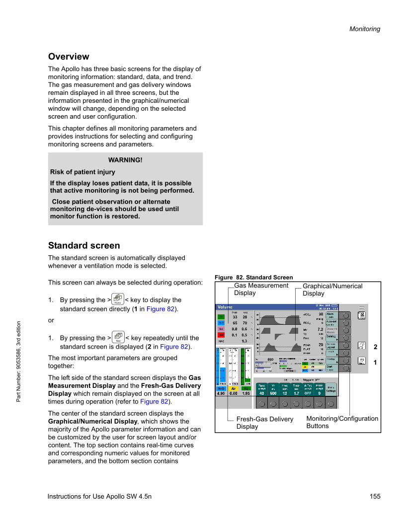
Monitoring
Par
t Num
ber:
905
3586
, 3rd
edi
tion
OverviewThe Apollo has three basic screens for the display of monitoring information: standard, data, and trend. The gas measurement and gas delivery windows remain displayed in all three screens, but the information presented in the graphical/numerical window will change, depending on the selected screen and user configuration.
This chapter defines all monitoring parameters and provides instructions for selecting and configuring monitoring screens and parameters.
Standard screenThe standard screen is automatically displayed whenever a ventilation mode is selected.
Figure 82. Standard ScreenThis screen can always be selected during operation:
1. By pressing the > < key to display the standard screen directly (1 in Figure 82).
or
1. By pressing the > < key repeatedly until the standard screen is displayed (2 in Figure 82).
The most important parameters are grouped together:
The left side of the standard screen displays the Gas Measurement Display and the Fresh-Gas Delivery Display which remain displayed on the screen at all times during operation (refer to Figure 82).
The center of the standard screen displays the Graphical/Numerical Display, which shows the majority of the Apollo parameter information and can be customized by the user for screen layout and/or content. The top section contains real-time curves and corresponding numeric values for monitored parameters, and the bottom section contains
WARNING!
Risk of patient injury
If the display loses patient data, it is possible that active monitoring is not being performed.
Close patient observation or alternate monitoring de-vices should be used until monitor function is restored.
1
2
Gas MeasurementDisplay
Graphical/NumericalDisplay
Fresh-Gas DeliveryDisplay
Monitoring/ConfigurationButtons
Instructions for Use Apollo SW 4.5n 155
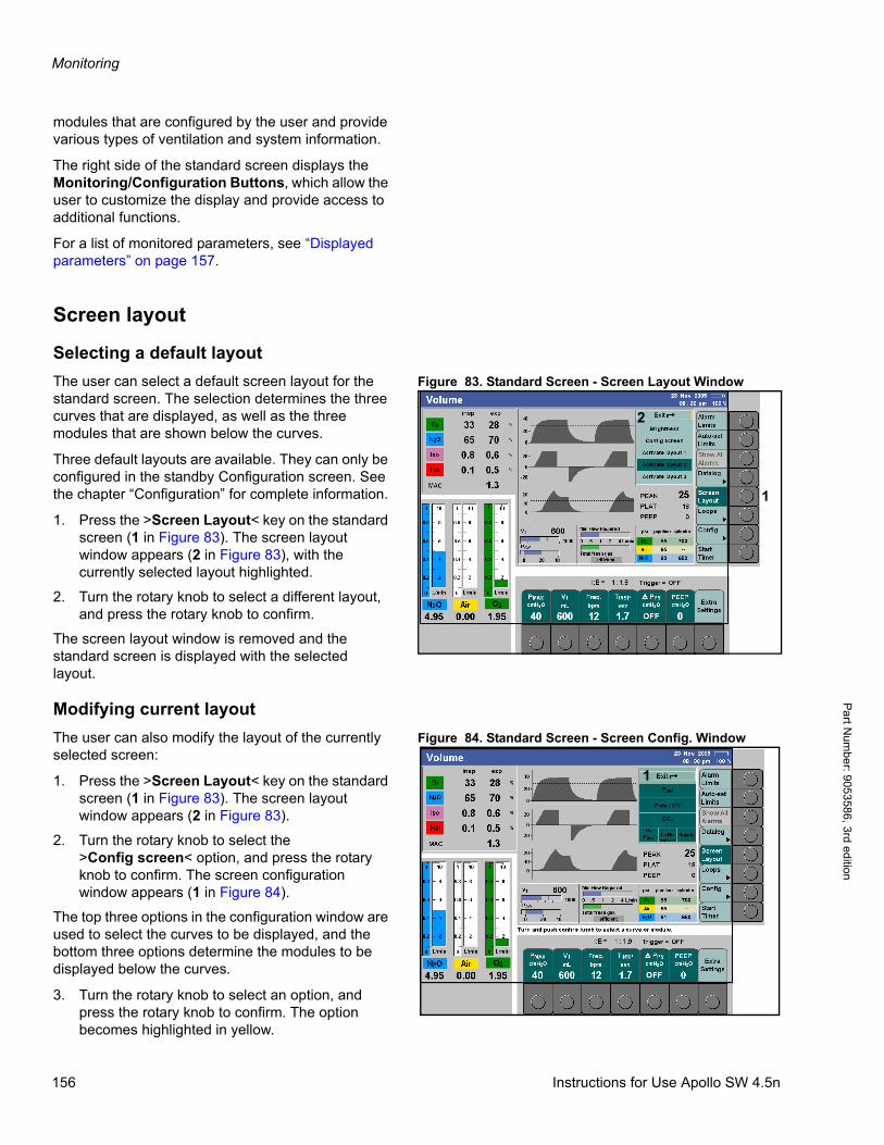
Monitoring
Pa
rt Num
ber: 905358
6, 3rd edition
modules that are configured by the user and provide various types of ventilation and system information.
The right side of the standard screen displays the Monitoring/Configuration Buttons, which allow the user to customize the display and provide access to additional functions.
For a list of monitored parameters, see “Displayed parameters” on page 157.
Screen layout
Selecting a default layout
Figure 83. Standard Screen - Screen Layout WindowThe user can select a default screen layout for the standard screen. The selection determines the three curves that are displayed, as well as the three modules that are shown below the curves.
Three default layouts are available. They can only be configured in the standby Configuration screen. See the chapter “Configuration” for complete information.
1. Press the >Screen Layout< key on the standard screen (1 in Figure 83). The screen layout window appears (2 in Figure 83), with the currently selected layout highlighted.
2. Turn the rotary knob to select a different layout, and press the rotary knob to confirm.
The screen layout window is removed and the standard screen is displayed with the selected layout.
Modifying current layout
Figure 84. Standard Screen - Screen Config. WindowThe user can also modify the layout of the currently selected screen:
1. Press the >Screen Layout< key on the standard screen (1 in Figure 83). The screen layout window appears (2 in Figure 83).
2. Turn the rotary knob to select the >Config screen< option, and press the rotary knob to confirm. The screen configuration window appears (1 in Figure 84).
The top three options in the configuration window are used to select the curves to be displayed, and the bottom three options determine the modules to be displayed below the curves.
3. Turn the rotary knob to select an option, and press the rotary knob to confirm. The option becomes highlighted in yellow.
1
2
1
156 Instructions for Use Apollo SW 4.5n
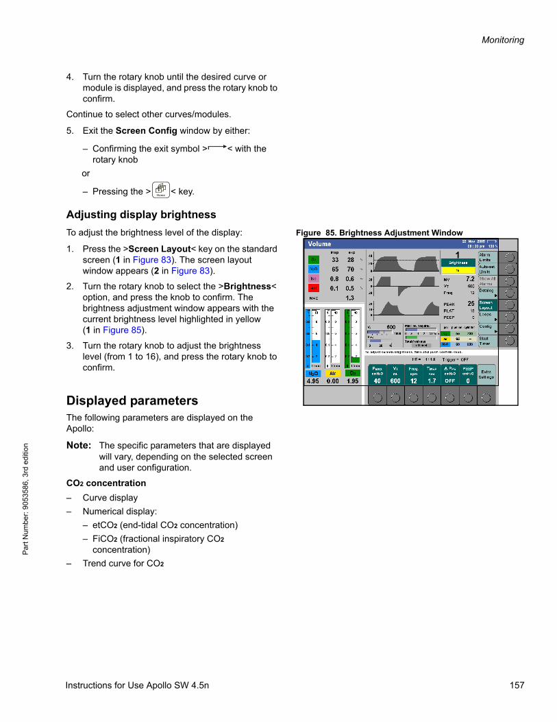
Monitoring
Par
t Num
ber:
905
3586
, 3rd
edi
tion
4. Turn the rotary knob until the desired curve or module is displayed, and press the rotary knob to confirm.
Continue to select other curves/modules.
5. Exit the Screen Config window by either:
– Confirming the exit symbol > < with the rotary knob
or
– Pressing the > < key.
Adjusting display brightness
Figure 85. Brightness Adjustment WindowTo adjust the brightness level of the display:
1. Press the >Screen Layout< key on the standard screen (1 in Figure 83). The screen layout window appears (2 in Figure 83).
2. Turn the rotary knob to select the >Brightness< option, and press the knob to confirm. The brightness adjustment window appears with the current brightness level highlighted in yellow(1 in Figure 85).
3. Turn the rotary knob to adjust the brightness level (from 1 to 16), and press the rotary knob to confirm.
Displayed parametersThe following parameters are displayed on the Apollo:
Note: The specific parameters that are displayed will vary, depending on the selected screen and user configuration.
CO2 concentration
– Curve display
– Numerical display:
– etCO2 (end-tidal CO2 concentration)
– FiCO2 (fractional inspiratory CO2 concentration)
– Trend curve for CO2
1
Instructions for Use Apollo SW 4.5n 157
Monitoring
Pa
rt Num
ber: 905358
6, 3rd edition
Note: The CO2 curve can be displayed in gray, dark gray, red, yellow, blue, or green. This setting can be configured by an authorized DrägerService representative.
O2 concentration
– Curve display
– Numerical display:
– FiO2 (fractional inspiratory O2 concentration)
– exO2 (expiratory O2 concentration)
– ΔO2 (difference between inspiratory and expiratory O2 concentration)
– Trend curve for O2
Anesthetic gas
– Curve display
– Numerical display:
– inAgent (inspiratory gas concentration)
– exAgent (expiratory gas concentration)
– MAC (minimum alveolar concentration)
– Trend curve for anesthetic gases and MAC
Airway pressure
– Curve display (PAW)
– Numerical display:
– PEAK (peak pressure)
– PLAT (plateau pressure)
– PEEP (positive end-expiratory pressure)
– MEAN (mean pressure) (only on data screen)
– Bar graph
Respiratory flow and volume
– Curve display for flow (insp/exp)
– Numerical display:
– MV (expiratory minute volume)
– VT (tidal volume)
– VTINSP (measured inspiratory tidal volume)
– ΔVT (difference between inspiratory and expiratory tidal volume)
– Freq. (respiratory rate)
– MVLEAK (difference between the inspiratory and expiratory minute volume) (only on data screen)
158 Instructions for Use Apollo SW 4.5n

Monitoring
Par
t Num
ber:
905
3586
, 3rd
edi
tion
– MVSPON spontaneously breathed expiratory minute volume
– MVMAND mandatory breathed expiratory minute volume
– CPAT* (patient lung compliance) (only on data screen)
– Trend curve for MV and CPAT
– VT bar graph
*CPAT = with mandatory breaths.
SpO2 concentration (Optional)
– Curve display (plethysmogram)
– Numerical display:
– SpO2 (functional O2 saturation level of blood)
– ♥ (pulse rate)
– Trend curve for SpO2 and pulse
Loops (Optional)
Graphical display for the following measured and calculated values:
– Pressure/Volume
– Flow/Volume
See “Loops (Optional)” on page 168 for more detailed information.
WARNING!
Risk of insufficient ventilation
The displayed spontaneous minute volume (MVSPON) indicates the volumes of the patient's breathing and the mechanical breathing support. If the mechanical breathing support is triggered by small tidal volumes of the patient, a major portion of the spontaneous minute volume is not achieved by the patient's breathing but the mechanical breathing support. In this case, MVSPON indicates a high value although the actual spontaneous minute volume is very low.
Do not make therapy decisions based solely on the displayed value of MVSPON.
VT
(PLAT - PEEP)
Instructions for Use Apollo SW 4.5n 159
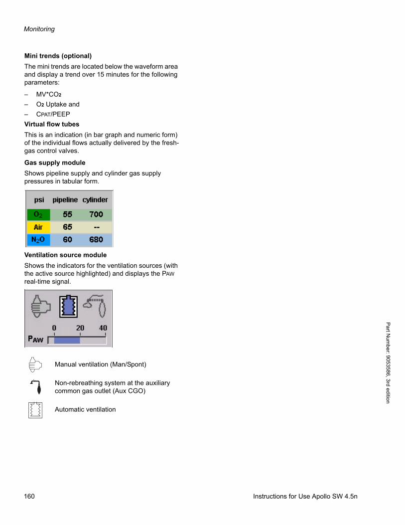
Monitoring
Pa
rt Num
ber: 905358
6, 3rd edition
Mini trends (optional)
The mini trends are located below the waveform area and display a trend over 15 minutes for the following parameters:
– MV*CO2
– O2 Uptake and
– CPAT/PEEP
Virtual flow tubes
This is an indication (in bar graph and numeric form) of the individual flows actually delivered by the fresh-gas control valves.
Gas supply module
Shows pipeline supply and cylinder gas supply pressures in tabular form.
Ventilation source module
Shows the indicators for the ventilation sources (with the active source highlighted) and displays the PAW real-time signal.
Manual ventilation (Man/Spont)
Non-rebreathing system at the auxiliary common gas outlet (Aux CGO)
Automatic ventilation
160 Instructions for Use Apollo SW 4.5n
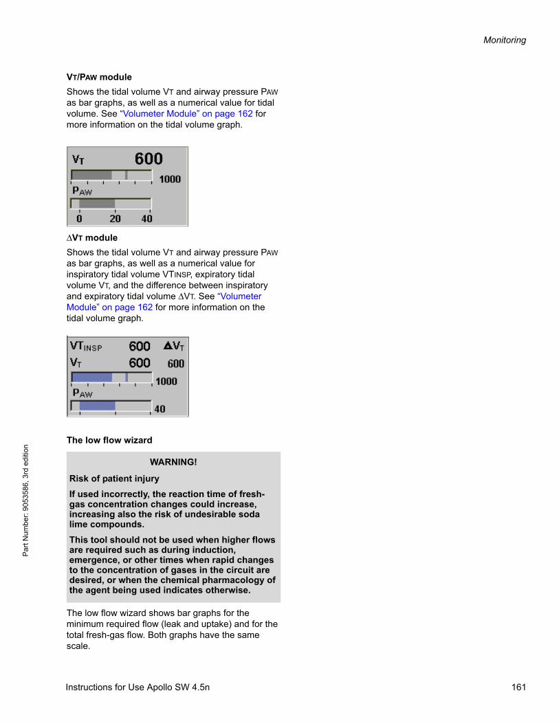
Monitoring
Par
t Num
ber:
905
3586
, 3rd
edi
tion
VT/PAW module
Shows the tidal volume VT and airway pressure PAW as bar graphs, as well as a numerical value for tidal volume. See “Volumeter Module” on page 162 for more information on the tidal volume graph.
ΔVT module
Shows the tidal volume VT and airway pressure PAW as bar graphs, as well as a numerical value for inspiratory tidal volume VTINSP, expiratory tidal volume VT, and the difference between inspiratory and expiratory tidal volume ΔVT. See “Volumeter Module” on page 162 for more information on the tidal volume graph.
The low flow wizard
The low flow wizard shows bar graphs for the minimum required flow (leak and uptake) and for the total fresh-gas flow. Both graphs have the same scale.
WARNING!
Risk of patient injury
If used incorrectly, the reaction time of fresh-gas concentration changes could increase, increasing also the risk of undesirable soda lime compounds.
This tool should not be used when higher flows are required such as during induction, emergence, or other times when rapid changes to the concentration of gases in the circuit are desired, or when the chemical pharmacology of the agent being used indicates otherwise.
Instructions for Use Apollo SW 4.5n 161
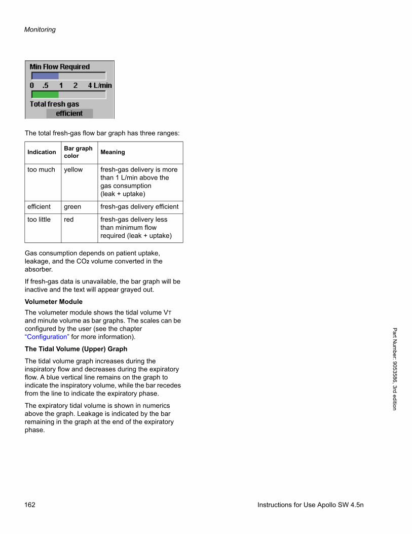
Monitoring
Pa
rt Num
ber: 905358
6, 3rd edition
The total fresh-gas flow bar graph has three ranges:
Gas consumption depends on patient uptake, leakage, and the CO2 volume converted in the absorber.
If fresh-gas data is unavailable, the bar graph will be inactive and the text will appear grayed out.
Volumeter Module
The volumeter module shows the tidal volume VT and minute volume as bar graphs. The scales can be configured by the user (see the chapter “Configuration” for more information).
The Tidal Volume (Upper) Graph
The tidal volume graph increases during the inspiratory flow and decreases during the expiratory flow. A blue vertical line remains on the graph to indicate the inspiratory volume, while the bar recedes from the line to indicate the expiratory phase.
The expiratory tidal volume is shown in numerics above the graph. Leakage is indicated by the bar remaining in the graph at the end of the expiratory phase.
IndicationBar graph color
Meaning
too much yellow fresh-gas delivery is more than 1 L/min above the gas consumption(leak + uptake)
efficient green fresh-gas delivery efficient
too little red fresh-gas delivery less than minimum flow required (leak + uptake)
162 Instructions for Use Apollo SW 4.5n
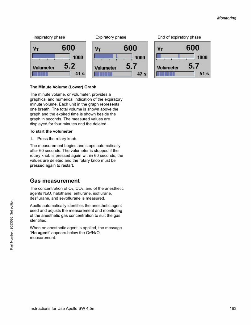
Monitoring
Par
t Num
ber:
905
3586
, 3rd
edi
tion
The Minute Volume (Lower) Graph
The minute volume, or volumeter, provides a graphical and numerical indication of the expiratory minute volume. Each unit in the graph represents one breath. The total volume is shown above the graph and the expired time is shown beside the graph in seconds. The measured values are displayed for four minutes and the deleted.
To start the volumeter
1. Press the rotary knob.
The measurement begins and stops automatically after 60 seconds. The volumeter is stopped if the rotary knob is pressed again within 60 seconds; the values are deleted and the rotary knob must be pressed again to restart.
Gas measurementThe concentration of O2, CO2, and of the anesthetic agents N2O, halothane, enflurane, isoflurane, desflurane, and sevoflurane is measured.
Apollo automatically identifies the anesthetic agent used and adjusts the measurement and monitoring of the anesthetic gas concentration to suit the gas identified.
When no anesthetic agent is applied, the message “No agent” appears below the O2/N2O measurement.
Inspiratory phase Expiratory phase End of expiratory phase
Instructions for Use Apollo SW 4.5n 163
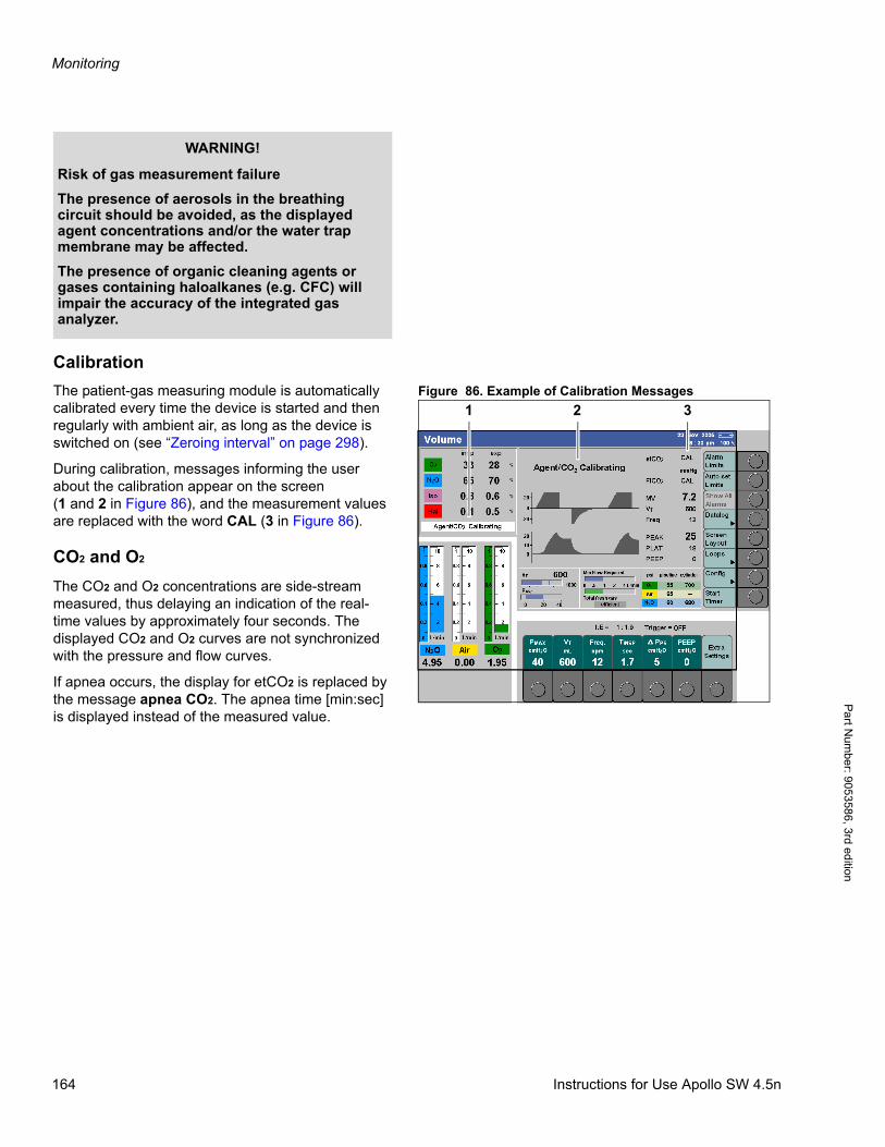
Monitoring
Pa
rt Num
ber: 905358
6, 3rd edition
Calibration
Figure 86. Example of Calibration MessagesThe patient-gas measuring module is automatically calibrated every time the device is started and then regularly with ambient air, as long as the device is switched on (see “Zeroing interval” on page 298).
During calibration, messages informing the user about the calibration appear on the screen(1 and 2 in Figure 86), and the measurement values are replaced with the word CAL (3 in Figure 86).
CO2 and O2
The CO2 and O2 concentrations are side-stream measured, thus delaying an indication of the real-time values by approximately four seconds. The displayed CO2 and O2 curves are not synchronized with the pressure and flow curves.
If apnea occurs, the display for etCO2 is replaced by the message apnea CO2. The apnea time [min:sec] is displayed instead of the measured value.
WARNING!
Risk of gas measurement failure
The presence of aerosols in the breathing circuit should be avoided, as the displayed agent concentrations and/or the water trap membrane may be affected.
The presence of organic cleaning agents or gases containing haloalkanes (e.g. CFC) will impair the accuracy of the integrated gas analyzer.
1 2 3
164 Instructions for Use Apollo SW 4.5n
Monitoring
Par
t Num
ber:
905
3586
, 3rd
edi
tion
Anesthetic agents
The anesthetic agents are side-stream measured in the same way as CO2 and O2.
Mixture detection
Apollo automatically detects the anesthetic gas used and switches the measurement and monitoring of anesthetic gas concentration to the gas detected.
If there is a mixture of two volatile anesthetic agents, the concentration of the secondary anesthetic agent is displayed if the xMAC value is 0.1 MAC or greater. The gas with the higher expiratory xMAC value is displayed above the secondary anesthetic agent.
A secondary anesthetic agent becomes the main anesthetic agent if its xMAC value exceeds the MAC value of the main anesthetic agent by 0.2 MAC.
A mixture of more than two volatile anesthetic agents cannot be reliably detected. In this case, the anesthetic gas values are no longer displayed and an alarm is generated.
Note: A mixture of more than two agents may lead to a temporary time-out of the measured O2 value.
WARNING!
Risk of patient injury
If the anesthetic agent displayed does not match the label of the anesthetic vaporizer being applied (open), make sure the vaporizer is filled correctly.
Instructions for Use Apollo SW 4.5n 165

Monitoring
Pa
rt Num
ber: 905358
6, 3rd edition
MAC definition
1 MAC is the anesthetic gas concentration in the blood at 760 mmHg (1013 hPa), at which 50% of patients no longer respond to a skin incision with movement.
The integrated MAC algorithm is based on the MAC values as indicated on the list. These values are merely guideline values. It is the information on the slip accompanying the anesthetic agents which is binding.
The MAC values are dependent on the age of the patient. The values indicated in the table relate to an age of 40 years.
Age-dependent MAC values
Figure 87. Influence of Age on MACThe MAC values used in Apollo are corrected for age. Therefore make sure that the age of the patient is entered correctly. Calculation follows the equation from W.W. Mapleson (British Journal of Anaesthesia 1996, P. 179-185). The equation applies to patients older than 1 year of age.
MACage-corrected = MAC 40 x 10 (-0.00269 x (age - 40))
The formula shows the reciprocal relationship existing between MAC and age.
Apollo automatically adjusts the MAC calculation according to the ambient pressure.
Note: The age “1” is used when the age is set to “<1”. Special attention is required for patients younger than one year.
1 MAC corresponds to:(in 100 % O2)
Halothane 0.77 Vol.%
Enflurane 1.7 Vol.%
Isoflurane 1.15 Vol.%
Desflurane 6.0 Vol.%
Sevoflurane 2.1 Vol.%
N2O 105 Vol.%
0.2*N2O
Desflurane
Sevoflurane
Enflurane
Isoflurane
Halothane
Age (years)
Influence of age on the MAC value
166 Instructions for Use Apollo SW 4.5n
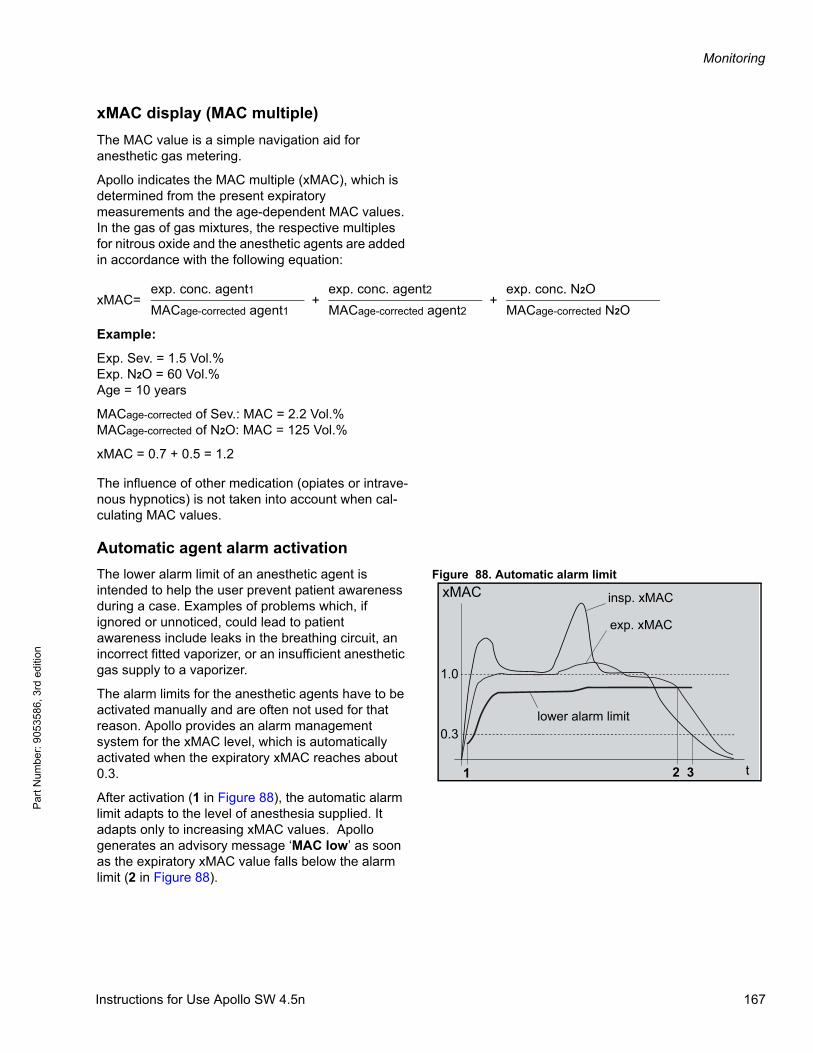
Monitoring
Par
t Num
ber:
905
3586
, 3rd
edi
tion
xMAC display (MAC multiple)
The MAC value is a simple navigation aid for anesthetic gas metering.
Apollo indicates the MAC multiple (xMAC), which is determined from the present expiratory measurements and the age-dependent MAC values. In the gas of gas mixtures, the respective multiples for nitrous oxide and the anesthetic agents are added in accordance with the following equation:
Example:
Exp. Sev. = 1.5 Vol.%Exp. N2O = 60 Vol.%Age = 10 years
MACage-corrected of Sev.: MAC = 2.2 Vol.%MACage-corrected of N2O: MAC = 125 Vol.%
xMAC = 0.7 + 0.5 = 1.2
The influence of other medication (opiates or intrave-nous hypnotics) is not taken into account when cal-culating MAC values.
Automatic agent alarm activation
Figure 88. Automatic alarm limitThe lower alarm limit of an anesthetic agent is intended to help the user prevent patient awareness during a case. Examples of problems which, if ignored or unnoticed, could lead to patient awareness include leaks in the breathing circuit, an incorrect fitted vaporizer, or an insufficient anesthetic gas supply to a vaporizer.
The alarm limits for the anesthetic agents have to be activated manually and are often not used for that reason. Apollo provides an alarm management system for the xMAC level, which is automatically activated when the expiratory xMAC reaches about 0.3.
After activation (1 in Figure 88), the automatic alarm limit adapts to the level of anesthesia supplied. It adapts only to increasing xMAC values. Apollo generates an advisory message ‘MAC low’ as soon as the expiratory xMAC value falls below the alarm limit (2 in Figure 88).
xMAC=exp. conc. agent1
+exp. conc. agent2
+exp. conc. N2O
MACage-corrected agent1 MACage-corrected agent2 MACage-corrected N2O
t
1.0
0.3
1 2 3
xMAC insp. xMAC
exp. xMAC
lower alarm limit
Instructions for Use Apollo SW 4.5n 167

Monitoring
Pa
rt Num
ber: 905358
6, 3rd edition
Without confirmation the priority will automatically change to a caution after 30 sec. When the alarm message is present the alarm limit menu will automatically open and the confirmation field for the alarm ’MAC low OK?’ is preselected. The user can now confirm the alarm message by pressing the rotary knob.
The automatic agent alarm activation can be configured in the default configuration in Standby.
Loops (Optional)Display loops on the screen
Figure 89. Loops Key on Standard Screen1. Press the >Loops< button on the standard screen (1 in Figure 89).
The label of the button changes to >Exit Loops< and the P/V Loop and the Flow/Vol loop are displayed with a value table instead of the two lower curves (refer to Figure 90). Each loop remains on display for three breathing cycles; the color intensity of the loop decreases with each cycle.
The scale of the Pressure and Flow axes depends on the scale selected for the real-time curves. The scale of the volume axis depends on the scale in the VT/PAW module.
In addition to the factory setting for the axis orientation complying with ISO 80601-2-13, inverted display is also available. To change the display setting, contact service personnel.
See the chapter “Configuration” for more information on scale configuration.
1
168 Instructions for Use Apollo SW 4.5n
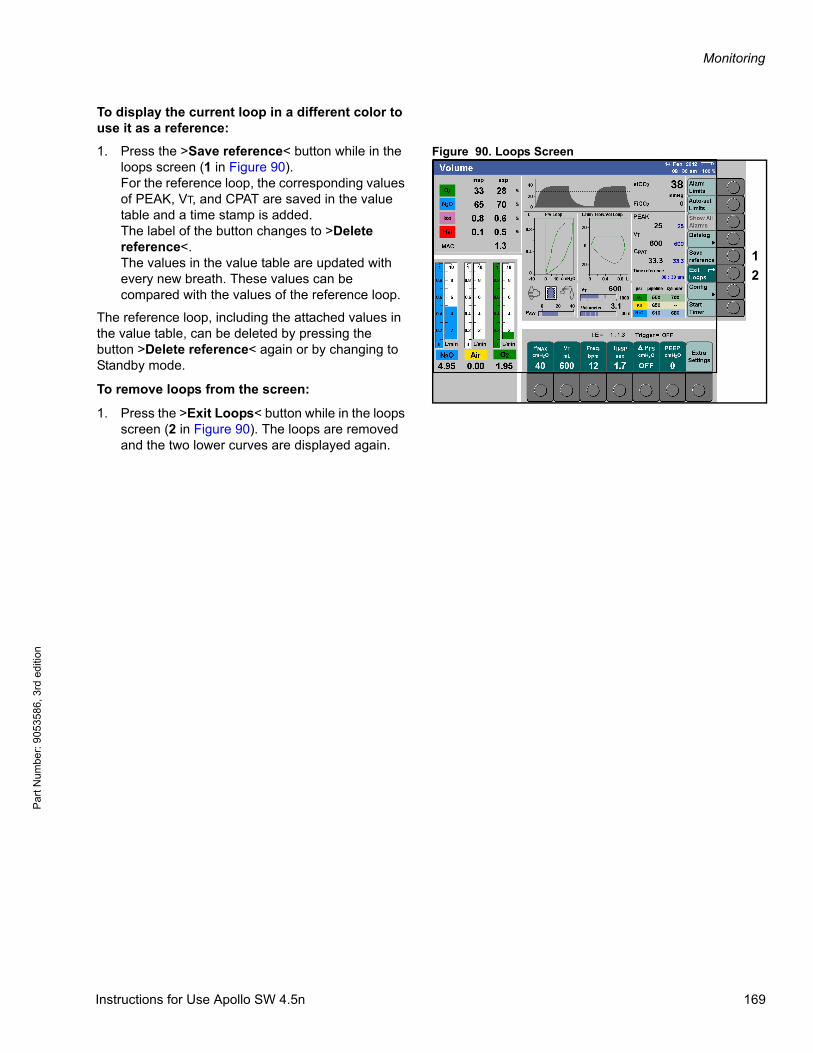
Monitoring
Par
t Num
ber:
905
3586
, 3rd
edi
tion
To display the current loop in a different color to use it as a reference:
Figure 90. Loops Screen1. Press the >Save reference< button while in the loops screen (1 in Figure 90). For the reference loop, the corresponding values of PEAK, VT, and CPAT are saved in the value table and a time stamp is added. The label of the button changes to >Delete reference<.The values in the value table are updated with every new breath. These values can be compared with the values of the reference loop.
The reference loop, including the attached values in the value table, can be deleted by pressing the button >Delete reference< again or by changing to Standby mode.
To remove loops from the screen:
1. Press the >Exit Loops< button while in the loops screen (2 in Figure 90). The loops are removed and the two lower curves are displayed again.
1
2
Instructions for Use Apollo SW 4.5n 169

Monitoring
Pa
rt Num
ber: 905358
6, 3rd edition
Mini trends (optional)There are 3 different mini trends available that can be displayed below the waveform area:
Figure 91 Select the corresponding mini trend– MV*CO2
– O2 uptake
– CPAT/PEEP
To configure a mini trend:
Press the >Screen layout< button (1 in Figure 91).
Select a parameter module and select the corresponding mini trend.
Mini trend for MV*CO2
Figure 92 Mini trend for MV*CO2This mini trend displays the expiratory minute volume in combination with expiratory CO2 concentration over 15 minutes.
The current value of MV*CO2 is displayed as numeric value above the mini trend.
The parameter MV*CO2 indicates the CO2 volume that is expired by the patient.
The scaling depends on the expiratory tidal volume VT and is automatically adjusted.
1
800
400
0
MV*CO2 5 mL/min
VTml
MV*CO2
50 50
150 150
500 500
1000 1000
170 Instructions for Use Apollo SW 4.5n
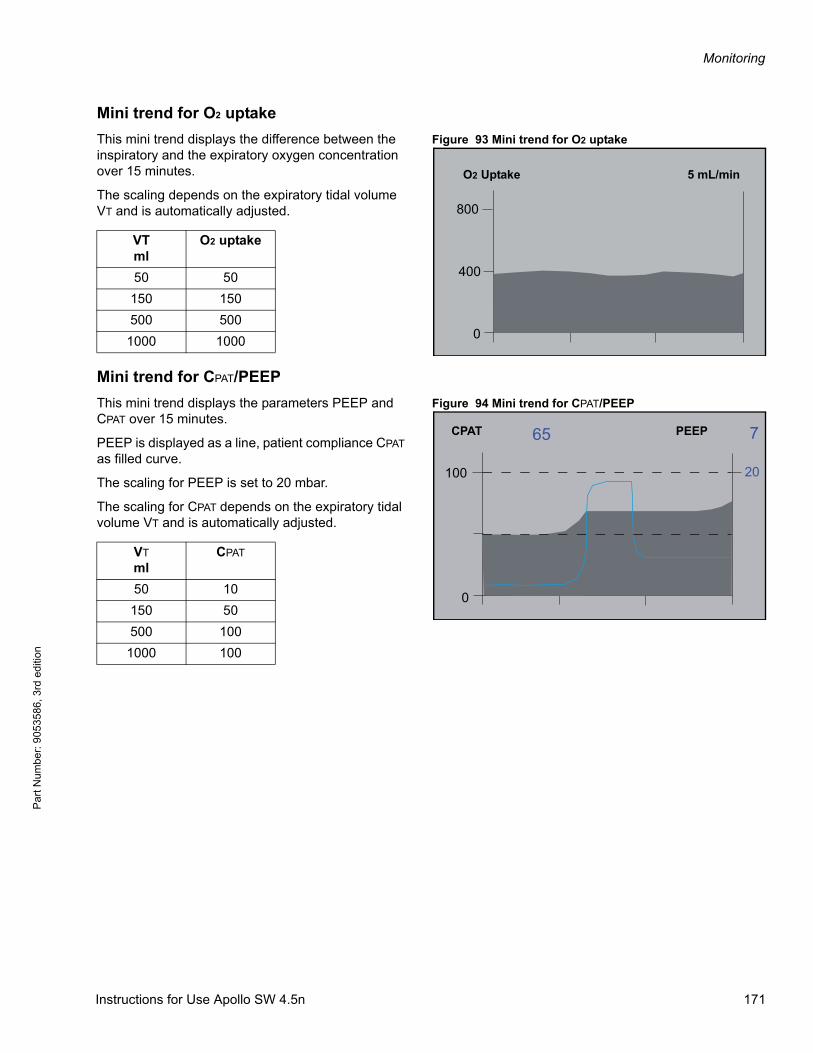
Monitoring
Par
t Num
ber:
905
3586
, 3rd
edi
tion
Mini trend for O2 uptake
Figure 93 Mini trend for O2 uptakeThis mini trend displays the difference between the inspiratory and the expiratory oxygen concentration over 15 minutes.
The scaling depends on the expiratory tidal volume VT and is automatically adjusted.
Mini trend for CPAT/PEEP
Figure 94 Mini trend for CPAT/PEEPThis mini trend displays the parameters PEEP and CPAT over 15 minutes.
PEEP is displayed as a line, patient compliance CPAT as filled curve.
The scaling for PEEP is set to 20 mbar.
The scaling for CPAT depends on the expiratory tidal volume VT and is automatically adjusted.
800
400
0
O2 Uptake 5 mL/min
VTml
O2 uptake
50 50
150 150
500 500
1000 1000
100
0
20
765CPAT PEEP
VT
mlCPAT
50 10
150 50
500 100
1000 100
Instructions for Use Apollo SW 4.5n 171
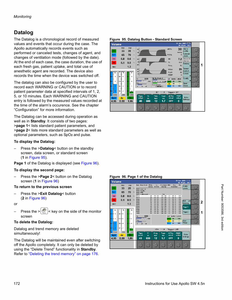
Monitoring
Pa
rt Num
ber: 905358
6, 3rd edition
DatalogFigure 95. Datalog Button - Standard ScreenThe Datalog is a chronological record of measured
values and events that occur during the case. The Apollo automatically records events such as performed or canceled tests, changes of agent, and changes of ventilation mode (followed by the date). At the end of each case, the case duration, the use of each fresh gas, patient uptake, and total use of anesthetic agent are recorded. The device also records the time when the device was switched off.
The datalog can also be configured by the user to record each WARNING or CAUTION or to record patient parameter data at specified intervals of 1, 2, 5, or 10 minutes. Each WARNING and CAUTION entry is followed by the measured values recorded at the time of the alarm’s occurence. See the chapter “Configuration” for more information.
The Datalog can be accessed during operation as well as in Standby. It consists of two pages:>page 1< lists standard patient parameters, and >page 2< lists more standard parameters as well as optional parameters, such as SpO2 and pulse.
To display the Datalog:
– Press the >Datalog< button on the standby screen, data screen, or standard screen(1 in Figure 95).
Page 1 of the Datalog is displayed (see Figure 96).
To display the second page:
Figure 96. Page 1 of the Datalog– Press the >Page 2< button on the Datalog screen (1 in Figure 96)
To return to the previous screen
– Press the >Exit Datalog< button(2 in Figure 96)
or
– Press the > < key on the side of the monitor screen
To delete the Datalog:
Datalog and trend memory are deleted simultaneously!
The Datalog will be maintained even after switching off the Apollo completely. It can only be deleted by using the “Delete Trend” functionality in Standby. Refer to “Deleting the trend memory” on page 176.
1
1
2
172 Instructions for Use Apollo SW 4.5n
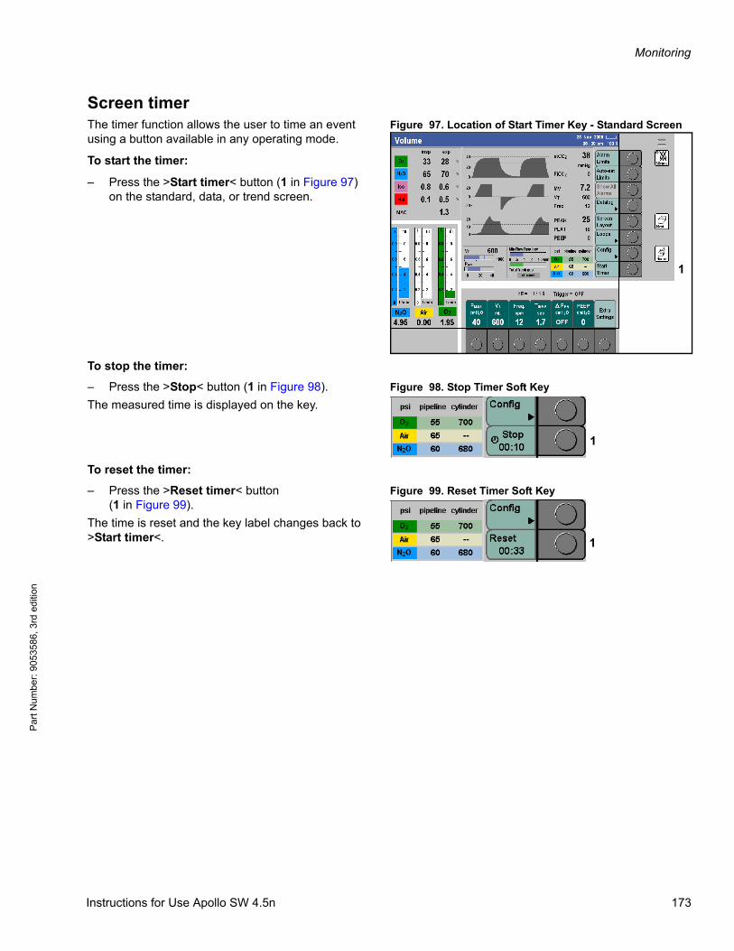
Monitoring
Par
t Num
ber:
905
3586
, 3rd
edi
tion
Screen timerFigure 97. Location of Start Timer Key - Standard ScreenThe timer function allows the user to time an event
using a button available in any operating mode.
To start the timer:
– Press the >Start timer< button (1 in Figure 97) on the standard, data, or trend screen.
To stop the timer:
Figure 98. Stop Timer Soft Key– Press the >Stop< button (1 in Figure 98).
The measured time is displayed on the key.
To reset the timer:
Figure 99. Reset Timer Soft Key– Press the >Reset timer< button(1 in Figure 99).
The time is reset and the key label changes back to >Start timer<.
1
1
1
Instructions for Use Apollo SW 4.5n 173
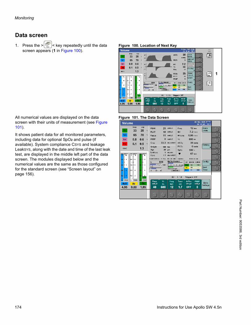
Monitoring
Pa
rt Num
ber: 905358
6, 3rd edition
Data screen
Figure 100. Location of Next Key1. Press the > < key repeatedly until the data screen appears (1 in Figure 100).
Figure 101. The Data ScreenAll numerical values are displayed on the data screen with their units of measurement (see Figure 101).
It shows patient data for all monitored parameters, including data for optional SpO2 and pulse (if available). System compliance CSYS and leakage LeakSYS, along with the date and time of the last leak test, are displayed in the middle left part of the data screen. The modules displayed below and the numerical values are the same as those configured for the standard screen (see “Screen layout” on page 156).
1
174 Instructions for Use Apollo SW 4.5n
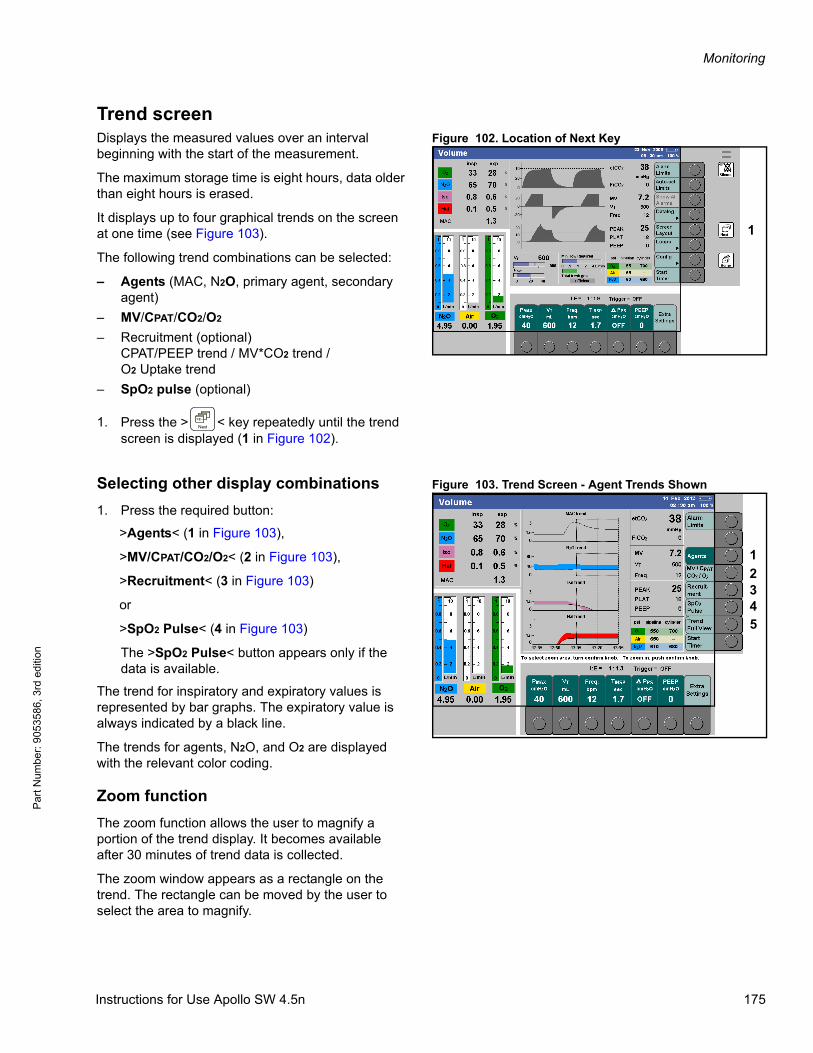
Monitoring
Par
t Num
ber:
905
3586
, 3rd
edi
tion
Trend screenFigure 102. Location of Next KeyDisplays the measured values over an interval
beginning with the start of the measurement.
The maximum storage time is eight hours, data older than eight hours is erased.
It displays up to four graphical trends on the screen at one time (see Figure 103).
The following trend combinations can be selected:
– Agents (MAC, N2O, primary agent, secondary agent)
– MV/CPAT/CO2/O2
– Recruitment (optional)CPAT/PEEP trend / MV*CO2 trend /O2 Uptake trend
– SpO2 pulse (optional)
1. Press the > < key repeatedly until the trend screen is displayed (1 in Figure 102).
Figure 103. Trend Screen - Agent Trends ShownSelecting other display combinations
1. Press the required button:
>Agents< (1 in Figure 103),
>MV/CPAT/CO2/O2< (2 in Figure 103),
>Recruitment< (3 in Figure 103)
or
>SpO2 Pulse< (4 in Figure 103)
The >SpO2 Pulse< button appears only if the data is available.
The trend for inspiratory and expiratory values is represented by bar graphs. The expiratory value is always indicated by a black line.
The trends for agents, N2O, and O2 are displayed with the relevant color coding.
Zoom function
The zoom function allows the user to magnify a portion of the trend display. It becomes available after 30 minutes of trend data is collected.
The zoom window appears as a rectangle on the trend. The rectangle can be moved by the user to select the area to magnify.
1
1
2345
Instructions for Use Apollo SW 4.5n 175
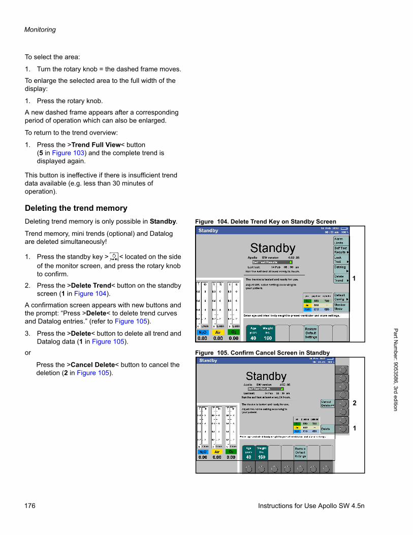
Monitoring
Pa
rt Num
ber: 905358
6, 3rd edition
To select the area:
1. Turn the rotary knob = the dashed frame moves.
To enlarge the selected area to the full width of the display:
1. Press the rotary knob.
A new dashed frame appears after a corresponding period of operation which can also be enlarged.
To return to the trend overview:
1. Press the >Trend Full View< button(5 in Figure 103) and the complete trend is displayed again.
This button is ineffective if there is insufficient trend data available (e.g. less than 30 minutes of operation).
Deleting the trend memory
Figure 104. Delete Trend Key on Standby ScreenDeleting trend memory is only possible in Standby.
Trend memory, mini trends (optional) and Datalog are deleted simultaneously!
1. Press the standby key > < located on the side of the monitor screen, and press the rotary knob to confirm.
2. Press the >Delete Trend< button on the standby screen (1 in Figure 104).
A confirmation screen appears with new buttons and the prompt: “Press >Delete< to delete trend curves and Datalog entries.” (refer to Figure 105).
3. Press the >Delete< button to delete all trend and Datalog data (1 in Figure 105).
Figure 105. Confirm Cancel Screen in Standbyor
Press the >Cancel Delete< button to cancel the deletion (2 in Figure 105).
1
1
2
176 Instructions for Use Apollo SW 4.5n
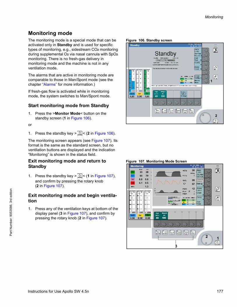
Monitoring
Par
t Num
ber:
905
3586
, 3rd
edi
tion
Monitoring modeFigure 106. Standby screenThe monitoring mode is a special mode that can be
activated only in Standby and is used for specific types of monitoring, e.g., sidestream CO2 monitoring during supplemental O2 via nasal cannula with SpO2 monitoring. There is no fresh-gas delivery in monitoring mode and the machine is not in any ventilation mode.
The alarms that are active in monitoring mode are comparable to those in Man/Spont mode (see the chapter “Alarms” for more information.)
If fresh-gas flow is activated while in monitoring mode, the system switches to Man/Spont mode.
Start monitoring mode from Standby
1. Press the >Monitor Mode< button on the standby screen (1 in Figure 106).
or
1. Press the standby key > < (2 in Figure 106).
The monitoring screen appears (see Figure 107). Its format is the same as the standard screen, but no ventilation buttons are displayed and the indication “Monitoring” is shown in the status field.
Figure 107. Monitoring Mode ScreenExit monitoring mode and return to Standby
1. Press the standby key > < (1 in Figure 107), and confirm by pressing the rotary knob(2 in Figure 107).
Exit monitoring mode and begin ventila-tion
1. Press any of the ventilation keys at bottom of the display panel (3 in Figure 107), and confirm by pressing the rotary knob (2 in Figure 107).
Vol. AFMode
1
2
Vol. AFMode
12
3
Instructions for Use Apollo SW 4.5n 177
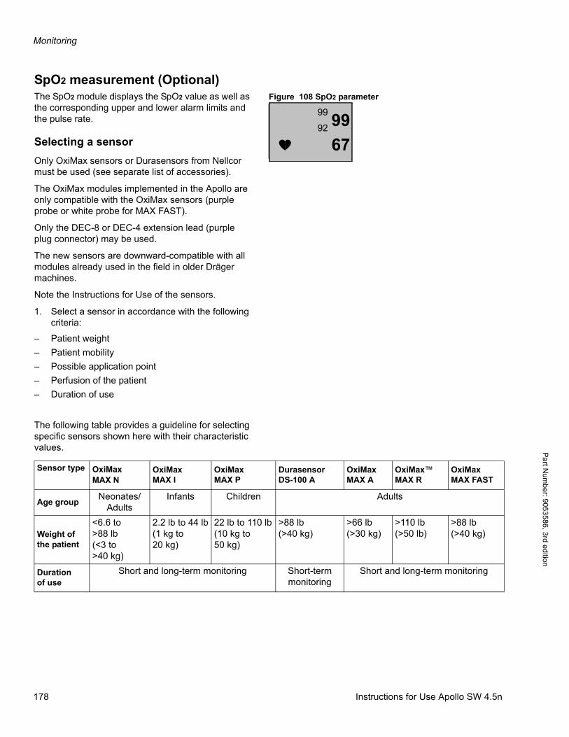
Monitoring
Pa
rt Num
ber: 905358
6, 3rd edition
SpO2 measurement (Optional)Figure 108 SpO2 parameterThe SpO2 module displays the SpO2 value as well as
the corresponding upper and lower alarm limits and the pulse rate.
Selecting a sensor
Only OxiMax sensors or Durasensors from Nellcor must be used (see separate list of accessories).
The OxiMax modules implemented in the Apollo are only compatible with the OxiMax sensors (purple probe or white probe for MAX FAST).
Only the DEC-8 or DEC-4 extension lead (purple plug connector) may be used.
The new sensors are downward-compatible with all modules already used in the field in older Dräger machines.
Note the Instructions for Use of the sensors.
1. Select a sensor in accordance with the following criteria:
– Patient weight
– Patient mobility
– Possible application point
– Perfusion of the patient
– Duration of use
The following table provides a guideline for selecting specific sensors shown here with their characteristic values.
9967
99
92
Sensor type OxiMaxMAX N
OxiMaxMAX I
OxiMaxMAX P
DurasensorDS-100 A
OxiMaxMAX A
OxiMax™MAX R
OxiMaxMAX FAST
Age groupNeonates/
AdultsInfants Children Adults
Weight of the patient
<6.6 to >88 lb(<3 to >40 kg)
2.2 lb to 44 lb(1 kg to 20 kg)
22 lb to 110 lb(10 kg to 50 kg)
>88 lb(>40 kg)
>66 lb(>30 kg)
>110 lb(>50 lb)
>88 lb(>40 kg)
Duration of use
Short and long-term monitoring Short-term monitoring
Short and long-term monitoring
178 Instructions for Use Apollo SW 4.5n
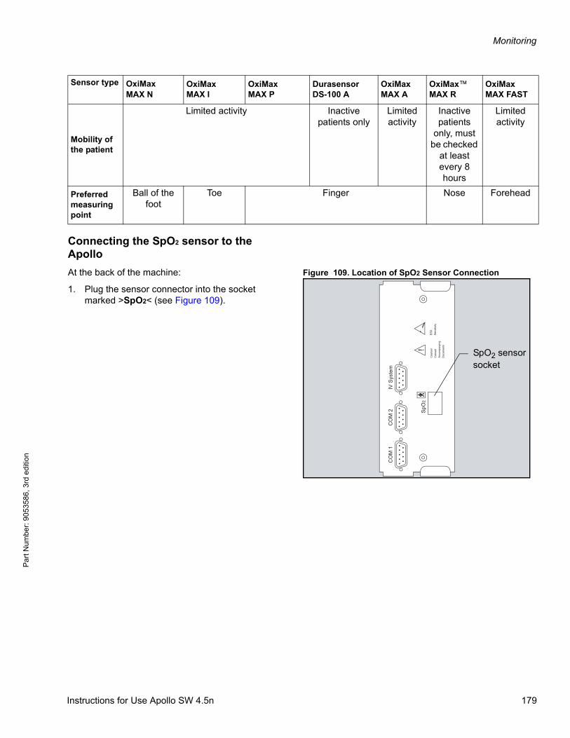
Monitoring
Par
t Num
ber:
905
3586
, 3rd
edi
tion
Connecting the SpO2 sensor to the Apollo
Figure 109. Location of SpO2 Sensor ConnectionAt the back of the machine:
1. Plug the sensor connector into the socket marked >SpO2< (see Figure 109).
Mobility of the patient
Limited activity Inactive patients only
Limited activity
Inactive patients
only, must be checked
at least every 8 hours
Limited activity
Preferred measuring point
Ball of the foot
Toe Finger Nose Forehead
Sensor type OxiMaxMAX N
OxiMaxMAX I
OxiMaxMAX P
DurasensorDS-100 A
OxiMaxMAX A
OxiMax™MAX R
OxiMaxMAX FAST
CO
M 1
CO
M 2
IV S
yste
m
SpO
2!
Cau
tion!
Con
sult
Acco
mpa
nyin
gD
ocum
ents
ESD
Sens
itivi
ty
SpO2 sensorsocket
Instructions for Use Apollo SW 4.5n 179
Monitoring
Pa
rt Num
ber: 905358
6, 3rd edition
Safety-relevant information
WARNING!
Risk of electric shock
If the SpO2 sensor becomes damaged during use, discontinue use, especially if there are uncovered electrical contacts.
WARNING!
Risk of patient injury
Incorrectly positioned sensors may result in incorrect measurements which may lead to patient injury.
Only use Nellcor sensors in the recommended positions.
CAUTION!
Risk of patient injury
The Apollo anesthesia machine has been verified to function with Nellcor pulse oximeter probes. The use of other probes may result in patient injury.
Use only verified probes with the Apollo.
WARNING!
Risk of patient injury
High intrathoracic pressure, pressure on the thorax and other consecutive impairments of the venous flow canlead to venous pulsation and pulse signal failure.
Do not position the SpO2 sensor where it might be affected in this way.
WARNING!
Risk of patient injury
If the SpO2 sensor is used in the presence of significant concentrations of dyshemoglobins, such as carboxyhemoglobin or methemoglobin, measurement accuracy may be reduced.
Do not rely on measurement data if the SpO2 sensor is used under these conditions.
WARNING!
Risk of patient injury
If the SpO2 sensor is used in the presence of intravascular dyes, such as methylene blue, measurement accuracy may be inaccurate.
Do not rely on measurement data if the SpO2 sensor is used under these conditions.
CAUTION!
Risk of misleading data
Immersing the SpO2 sensor in liquid may lead to a malfunction and thus misleading data.
Do not immerse the SpO2 sensor in liquid.
CAUTION!
Risk of failure or inaccurate data
If positioned close to a bright light source, the pulse signal may fail or the results may be inaccurate.
The sensor must be protected from exposure to bright light (e.g. surgical lamps and direct sunlight).
CAUTION!
Risk of failure or inaccurate data
If the sensor is positioned on limbs together with an arterial catheter, sphygmomanometer cuff or intravascular venous infusion, the pulse signal may fail and measurements may be inaccurate.
Do not position the SpO2 sensor where it might be affected in this way.
CAUTION!
Risk of failure or inaccurate data
Electrocautery can influence the measuring accuracy.
Leads and the SpO2 sensor should be positioned as far away from the electrocautery and its neutral electrode as possible.
180 Instructions for Use Apollo SW 4.5n
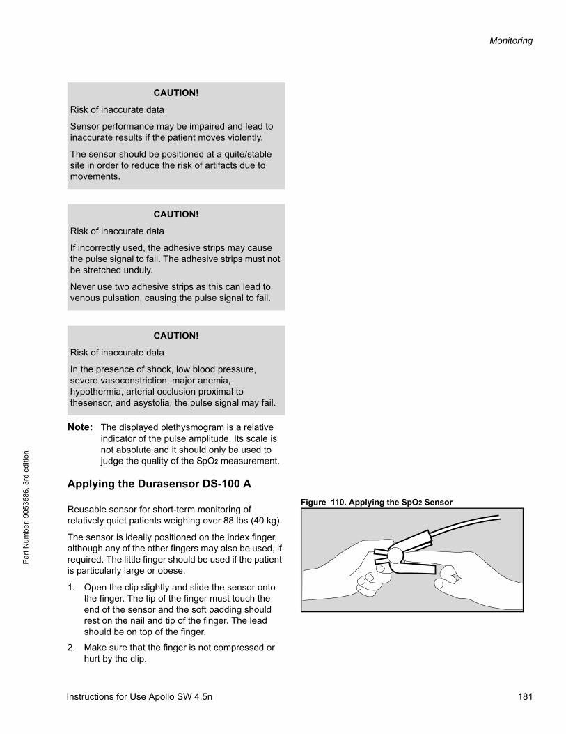
Monitoring
Par
t Num
ber:
905
3586
, 3rd
edi
tion
Note: The displayed plethysmogram is a relative indicator of the pulse amplitude. Its scale is not absolute and it should only be used to judge the quality of the SpO2 measurement.
Applying the Durasensor DS-100 A
Figure 110. Applying the SpO2 SensorReusable sensor for short-term monitoring of relatively quiet patients weighing over 88 lbs (40 kg).
The sensor is ideally positioned on the index finger, although any of the other fingers may also be used, if required. The little finger should be used if the patient is particularly large or obese.
1. Open the clip slightly and slide the sensor onto the finger. The tip of the finger must touch the end of the sensor and the soft padding should rest on the nail and tip of the finger. The lead should be on top of the finger.
2. Make sure that the finger is not compressed or hurt by the clip.
CAUTION!
Risk of inaccurate data
Sensor performance may be impaired and lead to inaccurate results if the patient moves violently.
The sensor should be positioned at a quite/stable site in order to reduce the risk of artifacts due to movements.
CAUTION!
Risk of inaccurate data
If incorrectly used, the adhesive strips may cause the pulse signal to fail. The adhesive strips must not be stretched unduly.
Never use two adhesive strips as this can lead to venous pulsation, causing the pulse signal to fail.
CAUTION!
Risk of inaccurate data
In the presence of shock, low blood pressure, severe vasoconstriction, major anemia, hypothermia, arterial occlusion proximal to thesensor, and asystolia, the pulse signal may fail.
Instructions for Use Apollo SW 4.5n 181
Monitoring
Pa
rt Num
ber: 905358
6, 3rd edition
3. Change the application site after not more than 4 hours in order to avoid a build-up of blood pressure (blocked circulation).
Follow the specific Instructions for Use when using other Nellcor sensors!
Test considerations and oximeter accu-racy
Functional testers and patient simulators
For functional testing of the pulse oximeter sensors and cables with a functional tester or patient simulator follow the individual testing device's operator's manual, especially regarding the suitability and accuracy of the simulated values.
CAUTION!
Risk of inaccurate data
If simulators are used as calibrators, the SpO2 module may produce incorrect data.
Simulators must not be used as calibrators.
182 Instructions for Use Apollo SW 4.5n
Alarms
Par
t Num
ber:
905
3586
, 3rd
edi
tion
Alarms
ContentsAlarm priorities and alarm signals . . . . . . . . . . . . . . . . . . . . . . . . . . . . . . . . . . . . . . . . . . . . . . . . . . . . . . . . . 185
Warning . . . . . . . . . . . . . . . . . . . . . . . . . . . . . . . . . . . . . . . . . . . . . . . . . . . . . . . . . . . . . . . . . . . . . . . . . . . . . . . 185
Caution . . . . . . . . . . . . . . . . . . . . . . . . . . . . . . . . . . . . . . . . . . . . . . . . . . . . . . . . . . . . . . . . . . . . . . . . . . . . . . . . 185
Advisory/technical message . . . . . . . . . . . . . . . . . . . . . . . . . . . . . . . . . . . . . . . . . . . . . . . . . . . . . . . . . . . . . . . . 185
Downgrading alarm priorities . . . . . . . . . . . . . . . . . . . . . . . . . . . . . . . . . . . . . . . . . . . . . . . . . . . . . . . . . . . . . . . 186
Setting the alarm volume . . . . . . . . . . . . . . . . . . . . . . . . . . . . . . . . . . . . . . . . . . . . . . . . . . . . . . . . . . . . . . . . . . 186
Alarms in Standby mode . . . . . . . . . . . . . . . . . . . . . . . . . . . . . . . . . . . . . . . . . . . . . . . . . . . . . . . . . . . . . . . . . . . 186
Alarm displays . . . . . . . . . . . . . . . . . . . . . . . . . . . . . . . . . . . . . . . . . . . . . . . . . . . . . . . . . . . . . . . . . . . . . . . . . 187
Suppressing alarms . . . . . . . . . . . . . . . . . . . . . . . . . . . . . . . . . . . . . . . . . . . . . . . . . . . . . . . . . . . . . . . . . . . . . 188
Silencing audible alarms . . . . . . . . . . . . . . . . . . . . . . . . . . . . . . . . . . . . . . . . . . . . . . . . . . . . . . . . . . . . . . . . . . . 188
Disabling alarms . . . . . . . . . . . . . . . . . . . . . . . . . . . . . . . . . . . . . . . . . . . . . . . . . . . . . . . . . . . . . . . . . . . . . . . . . 188
Alarm behaviour when changing ventilation modes . . . . . . . . . . . . . . . . . . . . . . . . . . . . . . . . . . . . . . . . . . . . . . 189
Limit-based alarms activated in respective ventilation modes . . . . . . . . . . . . . . . . . . . . . . . . . . . . . . . . . . 190
Enabling/disabling alarms globally during operation . . . . . . . . . . . . . . . . . . . . . . . . . . . . . . . . . . . . . . . . . . 191
Enabling/disabling CO2 alarms . . . . . . . . . . . . . . . . . . . . . . . . . . . . . . . . . . . . . . . . . . . . . . . . . . . . . . . . . . . . . 191
Enabling/disabling SpO2 alarms (Optional) . . . . . . . . . . . . . . . . . . . . . . . . . . . . . . . . . . . . . . . . . . . . . . . . . . . . 193
Bypass mode . . . . . . . . . . . . . . . . . . . . . . . . . . . . . . . . . . . . . . . . . . . . . . . . . . . . . . . . . . . . . . . . . . . . . . . . . . . 194
Displaying and setting alarm limits . . . . . . . . . . . . . . . . . . . . . . . . . . . . . . . . . . . . . . . . . . . . . . . . . . . . . . . . 195
To set an alarm limit . . . . . . . . . . . . . . . . . . . . . . . . . . . . . . . . . . . . . . . . . . . . . . . . . . . . . . . . . . . . . . . . . . . . . . 196
Auto-Set of alarm limits . . . . . . . . . . . . . . . . . . . . . . . . . . . . . . . . . . . . . . . . . . . . . . . . . . . . . . . . . . . . . . . . . . . 197
Instructions for Use Apollo SW 4.5n 183

Alarms
Pa
rt Num
ber: 905358
6, 3rd edition
This page intentionally left blank.
184 Instructions for Use Apollo SW 4.5n
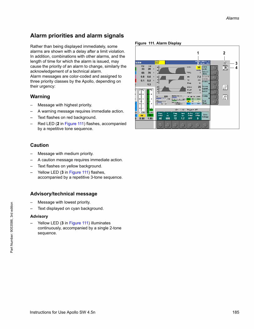
Alarms
Par
t Num
ber:
905
3586
, 3rd
edi
tion
Alarm priorities and alarm signalsFigure 111. Alarm Display
Rather than being displayed immediately, some alarms are shown with a delay after a limit violation. In addition, combinations with other alarms, and the length of time for which the alarm is issued, may cause the priority of an alarm to change, similarly the acknowledgement of a technical alarm.Alarm messages are color-coded and assigned to three priority classes by the Apollo, depending on their urgency:
Warning
– Message with highest priority.
– A warning message requires immediate action.
– Text flashes on red background.
– Red LED (2 in Figure 111) flashes, accompanied by a repetitive tone sequence.
Caution
– Message with medium priority.
– A caution message requires immediate action.
– Text flashes on yellow background.
– Yellow LED (3 in Figure 111) flashes, accompanied by a repetitive 3-tone sequence.
Advisory/technical message
– Message with lowest priority.
– Text displayed on cyan background.
Advisory
– Yellow LED (3 in Figure 111) illuminates continuously, accompanied by a single 2-tone sequence.
21
43
Instructions for Use Apollo SW 4.5n 185
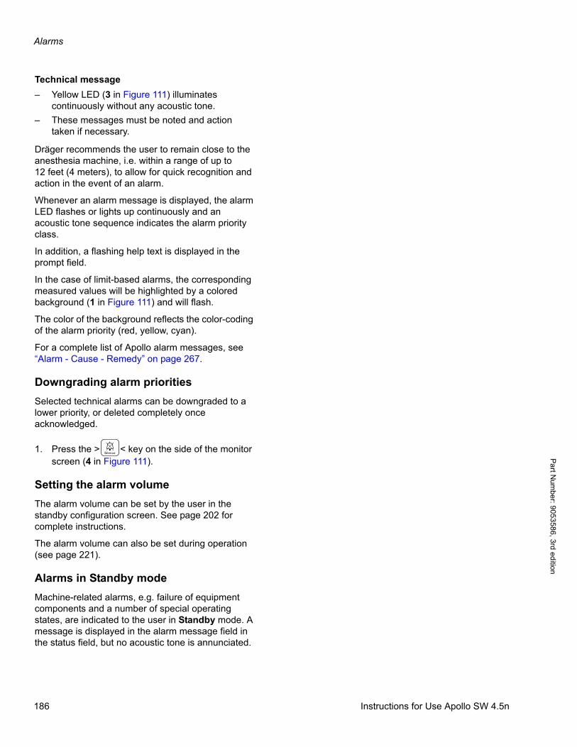
Alarms
Pa
rt Num
ber: 905358
6, 3rd edition
Technical message
– Yellow LED (3 in Figure 111) illuminates continuously without any acoustic tone.
– These messages must be noted and action taken if necessary.
Dräger recommends the user to remain close to the anesthesia machine, i.e. within a range of up to 12 feet (4 meters), to allow for quick recognition and action in the event of an alarm.
Whenever an alarm message is displayed, the alarm LED flashes or lights up continuously and an acoustic tone sequence indicates the alarm priority class.
In addition, a flashing help text is displayed in the prompt field.
In the case of limit-based alarms, the corresponding measured values will be highlighted by a colored background (1 in Figure 111) and will flash.
The color of the background reflects the color-coding of the alarm priority (red, yellow, cyan).
For a complete list of Apollo alarm messages, see “Alarm - Cause - Remedy” on page 267.
Downgrading alarm priorities
Selected technical alarms can be downgraded to a lower priority, or deleted completely once acknowledged.
1. Press the > < key on the side of the monitor screen (4 in Figure 111).
Setting the alarm volume
The alarm volume can be set by the user in the standby configuration screen. See page 202 for complete instructions.
The alarm volume can also be set during operation (see page 221).
Alarms in Standby mode
Machine-related alarms, e.g. failure of equipment components and a number of special operating states, are indicated to the user in Standby mode. A message is displayed in the alarm message field in the status field, but no acoustic tone is annunciated.
186 Instructions for Use Apollo SW 4.5n
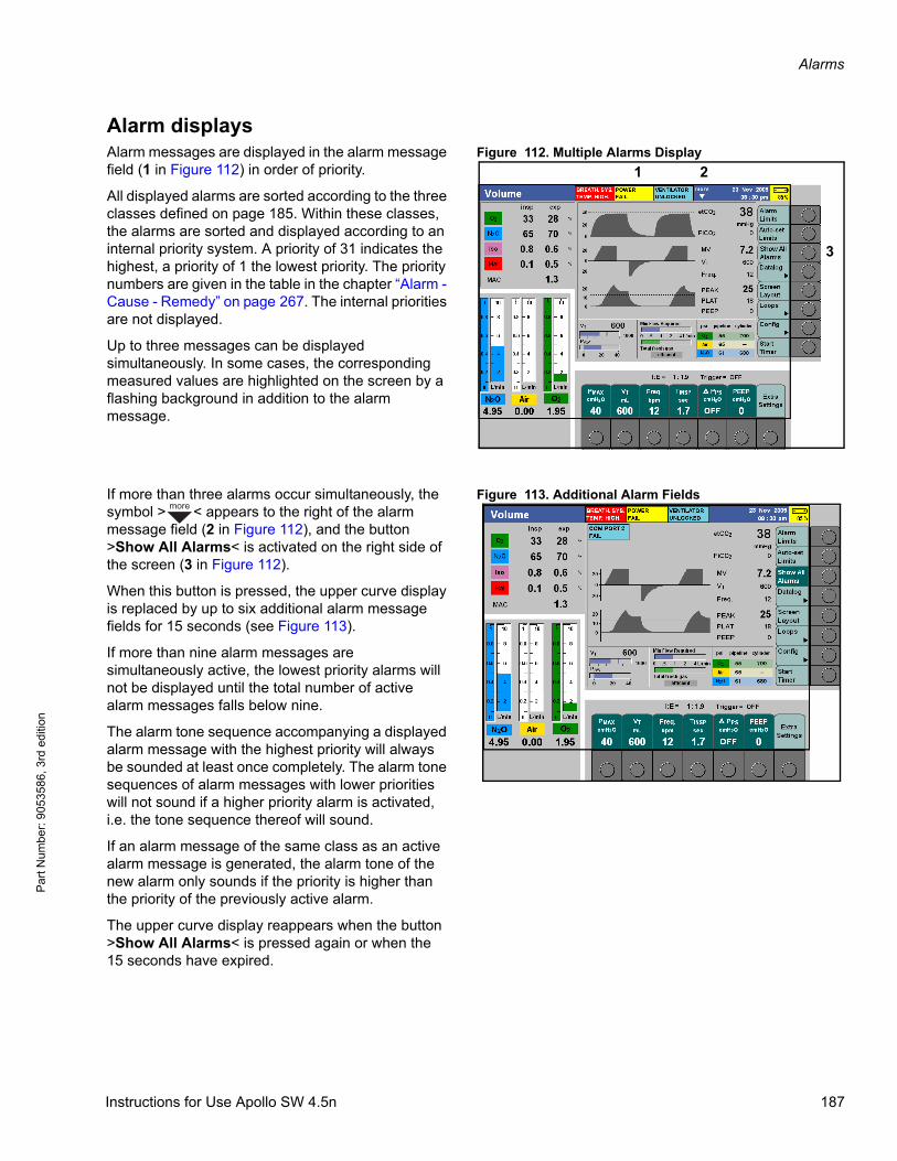
Alarms
Par
t Num
ber:
905
3586
, 3rd
edi
tion
Alarm displaysFigure 112. Multiple Alarms DisplayAlarm messages are displayed in the alarm message
field (1 in Figure 112) in order of priority.
All displayed alarms are sorted according to the three classes defined on page 185. Within these classes, the alarms are sorted and displayed according to an internal priority system. A priority of 31 indicates the highest, a priority of 1 the lowest priority. The priority numbers are given in the table in the chapter “Alarm - Cause - Remedy” on page 267. The internal priorities are not displayed.
Up to three messages can be displayed simultaneously. In some cases, the corresponding measured values are highlighted on the screen by a flashing background in addition to the alarm message.
Figure 113. Additional Alarm FieldsIf more than three alarms occur simultaneously, the symbol > < appears to the right of the alarm message field (2 in Figure 112), and the button >Show All Alarms< is activated on the right side of the screen (3 in Figure 112).
When this button is pressed, the upper curve display is replaced by up to six additional alarm message fields for 15 seconds (see Figure 113).
If more than nine alarm messages are simultaneously active, the lowest priority alarms will not be displayed until the total number of active alarm messages falls below nine.
The alarm tone sequence accompanying a displayed alarm message with the highest priority will always be sounded at least once completely. The alarm tone sequences of alarm messages with lower priorities will not sound if a higher priority alarm is activated, i.e. the tone sequence thereof will sound.
If an alarm message of the same class as an active alarm message is generated, the alarm tone of the new alarm only sounds if the priority is higher than the priority of the previously active alarm.
The upper curve display reappears when the button >Show All Alarms< is pressed again or when the 15 seconds have expired.
1
3
2
more
Instructions for Use Apollo SW 4.5n 187
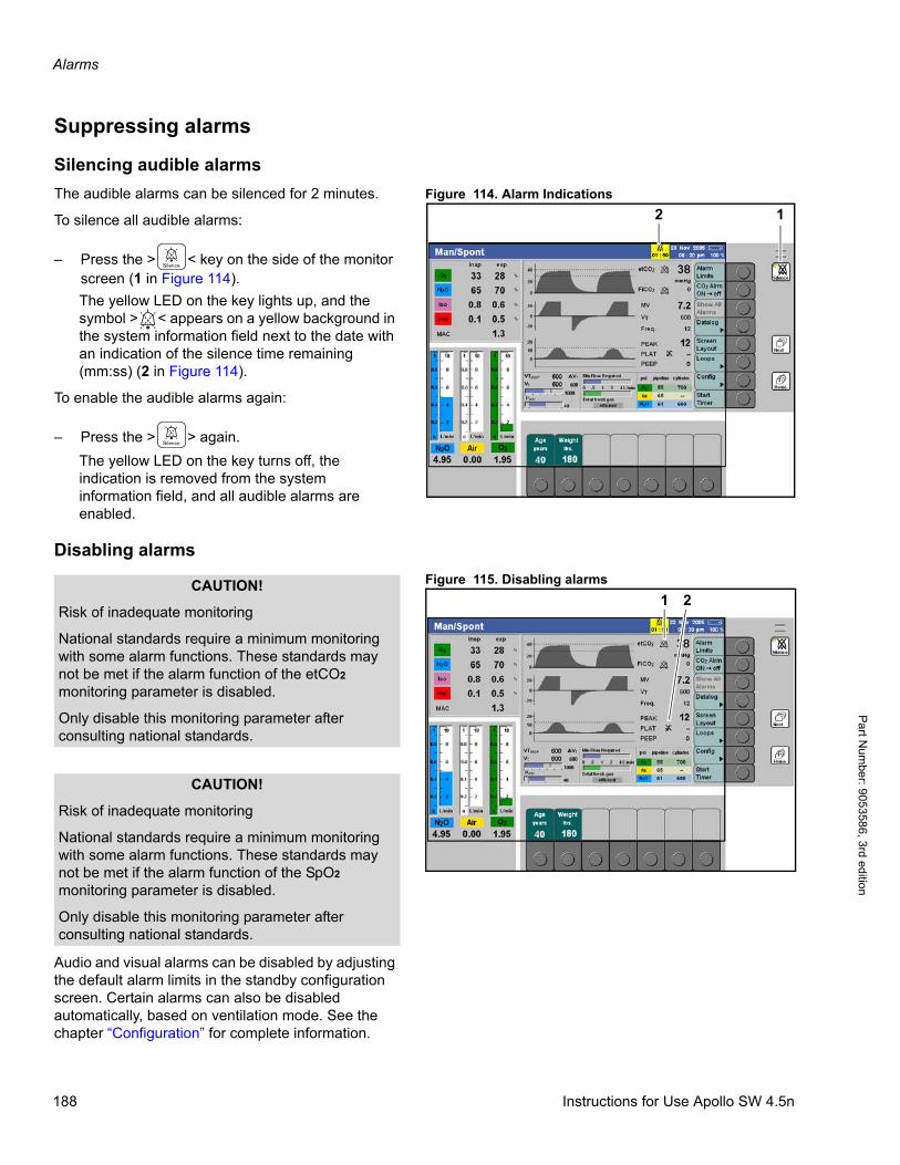
Alarms
Pa
rt Num
ber: 905358
6, 3rd edition
Suppressing alarms
Silencing audible alarms
Figure 114. Alarm IndicationsThe audible alarms can be silenced for 2 minutes.
To silence all audible alarms:
– Press the > < key on the side of the monitor screen (1 in Figure 114).
The yellow LED on the key lights up, and the symbol > < appears on a yellow background in the system information field next to the date with an indication of the silence time remaining (mm:ss) (2 in Figure 114).
To enable the audible alarms again:
– Press the > > again.
The yellow LED on the key turns off, the indication is removed from the system information field, and all audible alarms are enabled.
Disabling alarms
Figure 115. Disabling alarms
Audio and visual alarms can be disabled by adjusting the default alarm limits in the standby configuration screen. Certain alarms can also be disabled automatically, based on ventilation mode. See the chapter “Configuration” for complete information.
12
1 2CAUTION!
Risk of inadequate monitoring
National standards require a minimum monitoring with some alarm functions. These standards may not be met if the alarm function of the etCO2 monitoring parameter is disabled.
Only disable this monitoring parameter after consulting national standards.
CAUTION!
Risk of inadequate monitoring
National standards require a minimum monitoring with some alarm functions. These standards may not be met if the alarm function of the SpO2 monitoring parameter is disabled.
Only disable this monitoring parameter after consulting national standards.
188 Instructions for Use Apollo SW 4.5n
Alarms
Par
t Num
ber:
905
3586
, 3rd
edi
tion
During operation certain alarms can be disabled globally (see “Enabling/disabling alarms globally during operation” on page 191) or individually in the alarm limits menu (see “Displaying and setting alarm limits” on page 195).
If all the alarms connected to a measurement function have been disabled, the measured value will be marked with the symbol > < (1 in Figure 115).
If only certain alarm limits have been disabled for a monitoring parameter, one symbol > < or > < appears next to the parameter (2 in Figure 115).
If the upper and lower alarm limits of a monitoring parameter have been disabled, but the respective apnea monitoring feature is still active, the symbol > < appears next to the parameter.
If an apnea monitoring feature derived from a specific monitoring parameter has been disabled, that parameter will be marked with the symbol > <.
A monitoring parameter is always marked with the symbol > < if, after switching from Standby into a ventilation mode, a valid CO2 breathing phase has not yet been detected for the parameters O2, N2O, MV, or inspiratory and expiratory CO2, or respectively a valid pulse signal for SpO2. As soon as a breathing phase has been detected or valid pulse signals are available for SpO2, the symbol disappears.
Alarm behaviour when changing ventila-tion modes
The Apollo has an automatic suppression of active MV low and apnea alarms implemented, when changing ventilation modes.
This suppression applies when the user changes from a ventilation mode with a low mandatory ventilation support, such as ManSpont, to a ventilation mode with a higher mandatory ventilation, such as Volume Mode. After this timeout the alarms will only be generated again if the preconditions are valid.
If the ’MV low’ alarm is active during such a change, the alarm is suppressed for 45 sec (no alarm display and no audible tone). The apnea alarms can be suppressed for a certain time, depending on the ventilation settings in the new ventilation mode.
If the settings for freq/FreqMIN are < 6 bpm the apnea alarms will be suppressed for 30 sec, otherwise the timeout is 15 sec.
> <
_
Instructions for Use Apollo SW 4.5n 189
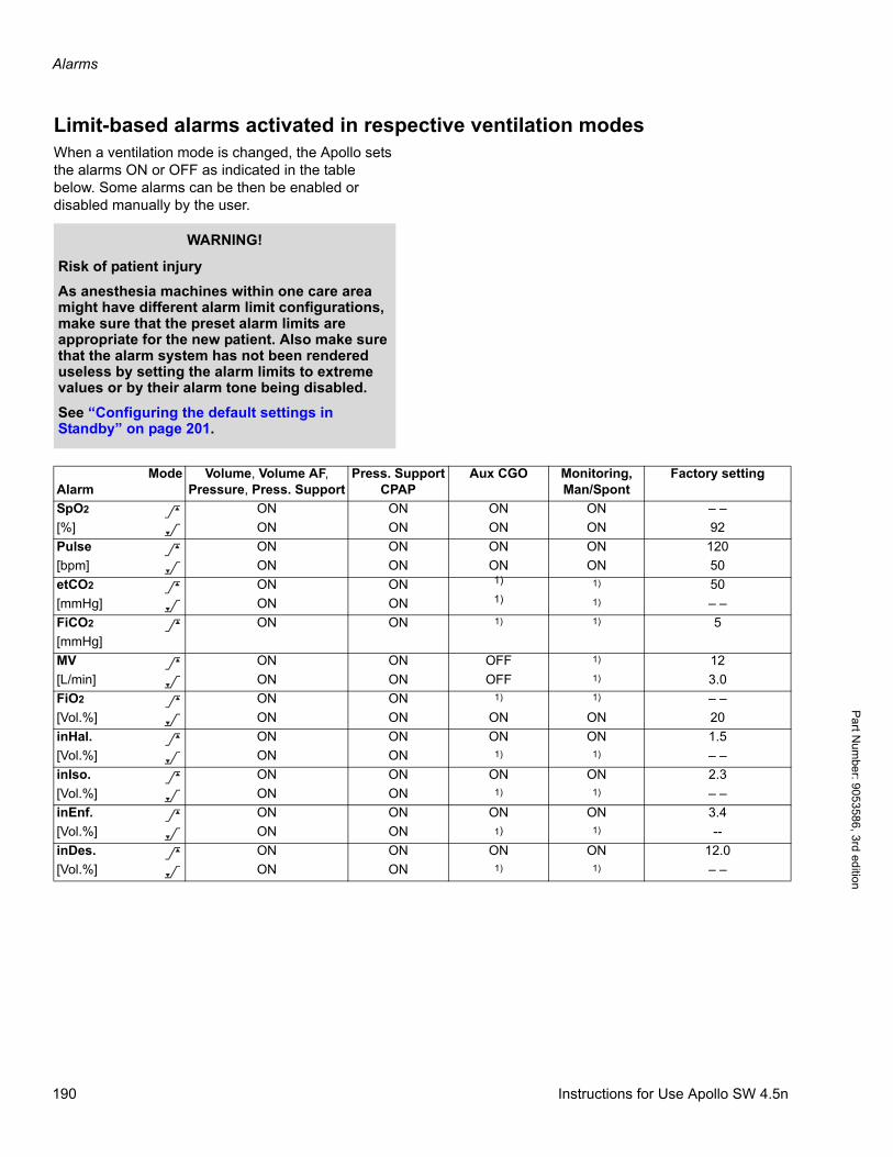
Alarms
Pa
rt Num
ber: 905358
6, 3rd edition
Limit-based alarms activated in respective ventilation modesWhen a ventilation mode is changed, the Apollo sets the alarms ON or OFF as indicated in the table below. Some alarms can be then be enabled or disabled manually by the user.
WARNING!
Risk of patient injury
As anesthesia machines within one care area might have different alarm limit configurations, make sure that the preset alarm limits are appropriate for the new patient. Also make sure that the alarm system has not been rendered useless by setting the alarm limits to extreme values or by their alarm tone being disabled.
See “Configuring the default settings in Standby” on page 201.
AlarmMode Volume, Volume AF,
Pressure, Press. SupportPress. Support
CPAPAux CGO Monitoring,
Man/SpontFactory setting
SpO2 ON ON ON ON – –
[%] ON ON ON ON 92
Pulse ON ON ON ON 120
[bpm] ON ON ON ON 50
etCO2 ON ON 1) 1) 50
[mmHg] ON ON 1) 1) – –
FiCO2 ON ON 1) 1) 5
[mmHg]
MV ON ON OFF 1) 12
[L/min] ON ON OFF 1) 3.0
FiO2 ON ON 1) 1) – –
[Vol.%] ON ON ON ON 20
inHal. ON ON ON ON 1.5
[Vol.%] ON ON 1) 1) – –
inIso. ON ON ON ON 2.3
[Vol.%] ON ON 1) 1) – –
inEnf. ON ON ON ON 3.4
[Vol.%] ON ON 1) 1) --
inDes. ON ON ON ON 12.0
[Vol.%] ON ON 1) 1) – –
><
><><
>
><
><
><
><
><
><
190 Instructions for Use Apollo SW 4.5n
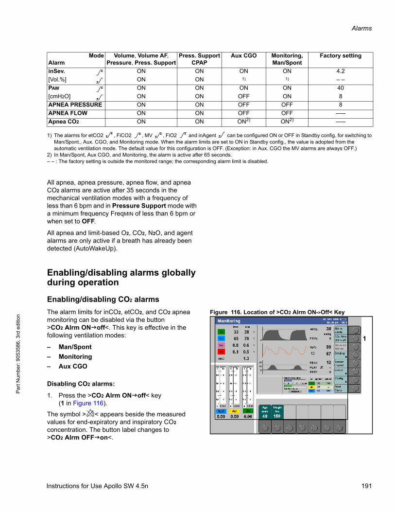
Alarms
Par
t Num
ber:
905
3586
, 3rd
edi
tion
All apnea, apnea pressure, apnea flow, and apnea CO2 alarms are active after 35 seconds in the mechanical ventilation modes with a frequency of less than 6 bpm and in Pressure Support mode with a minimum frequency FreqMIN of less than 6 bpm or when set to OFF.
All apnea and limit-based O2, CO2, N2O, and agent alarms are only active if a breath has already been detected (AutoWakeUp).
Enabling/disabling alarms globally during operation
Enabling/disabling CO2 alarms
Figure 116. Location of >CO2 Alrm ON->Off< KeyThe alarm limits for inCO2, etCO2, and CO2 apnea monitoring can be disabled via the button>CO2 Alrm ONoff<. This key is effective in the following ventilation modes:
– Man/Spont
– Monitoring
– Aux CGO
Disabling CO2 alarms:
1. Press the >CO2 Alrm ONoff< key(1 in Figure 116).
The symbol > < appears beside the measured values for end-expiratory and inspiratory CO2 concentration. The button label changes to >CO2 Alrm OFFon<.
inSev. ON ON ON ON 4.2
[Vol.%] ON ON 1) 1) – –
PAW ON ON ON ON 40
[cmH2O] ON ON OFF ON 8
APNEA PRESSURE ON ON OFF OFF 8
APNEA FLOW ON ON OFF OFF –––
Apnea CO2 ON ON ON2) ON2) –––
1) The alarms for etCO2 , FiCO2 , MV , FiO2 and inAgent can be configured ON or OFF in Standby config. for switching to Man/Spont., Aux. CGO, and Monitoring mode. When the alarm limits are set to ON in Standby config., the value is adopted from the automatic ventilation mode. The default value for this configuration is OFF. (Exception: in Aux. CGO the MV alarms are always OFF.)
2) In Man/Spont, Aux CGO, and Monitoring, the alarm is active after 65 seconds.– – : The factory setting is outside the monitored range; the corresponding alarm limit is disabled.
AlarmMode Volume, Volume AF,
Pressure, Press. SupportPress. Support
CPAPAux CGO Monitoring,
Man/SpontFactory setting
><
><
_ > _ > <
1
Instructions for Use Apollo SW 4.5n 191
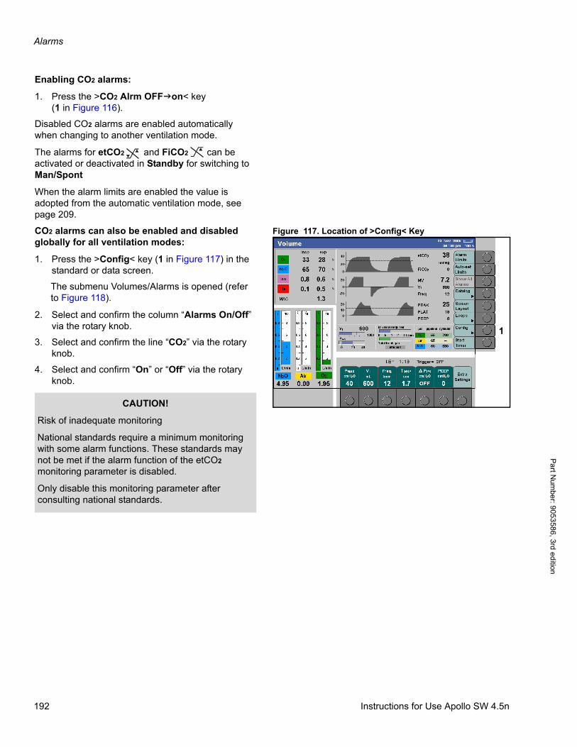
Alarms
Pa
rt Num
ber: 905358
6, 3rd edition
Enabling CO2 alarms:
1. Press the >CO2 Alrm OFFon< key(1 in Figure 116).
Disabled CO2 alarms are enabled automatically when changing to another ventilation mode.
The alarms for etCO2 and FiCO2 can be activated or deactivated in Standby for switching to Man/Spont
When the alarm limits are enabled the value is adopted from the automatic ventilation mode, see page 209.
Figure 117. Location of >Config< KeyCO2 alarms can also be enabled and disabled globally for all ventilation modes:
1. Press the >Config< key (1 in Figure 117) in the standard or data screen.
The submenu Volumes/Alarms is opened (refer to Figure 118).
2. Select and confirm the column “Alarms On/Off” via the rotary knob.
3. Select and confirm the line “CO2” via the rotary knob.
4. Select and confirm “On” or “Off” via the rotary knob.
_ >
1
CAUTION!
Risk of inadequate monitoring
National standards require a minimum monitoring with some alarm functions. These standards may not be met if the alarm function of the etCO2 monitoring parameter is disabled.
Only disable this monitoring parameter after consulting national standards.
192 Instructions for Use Apollo SW 4.5n
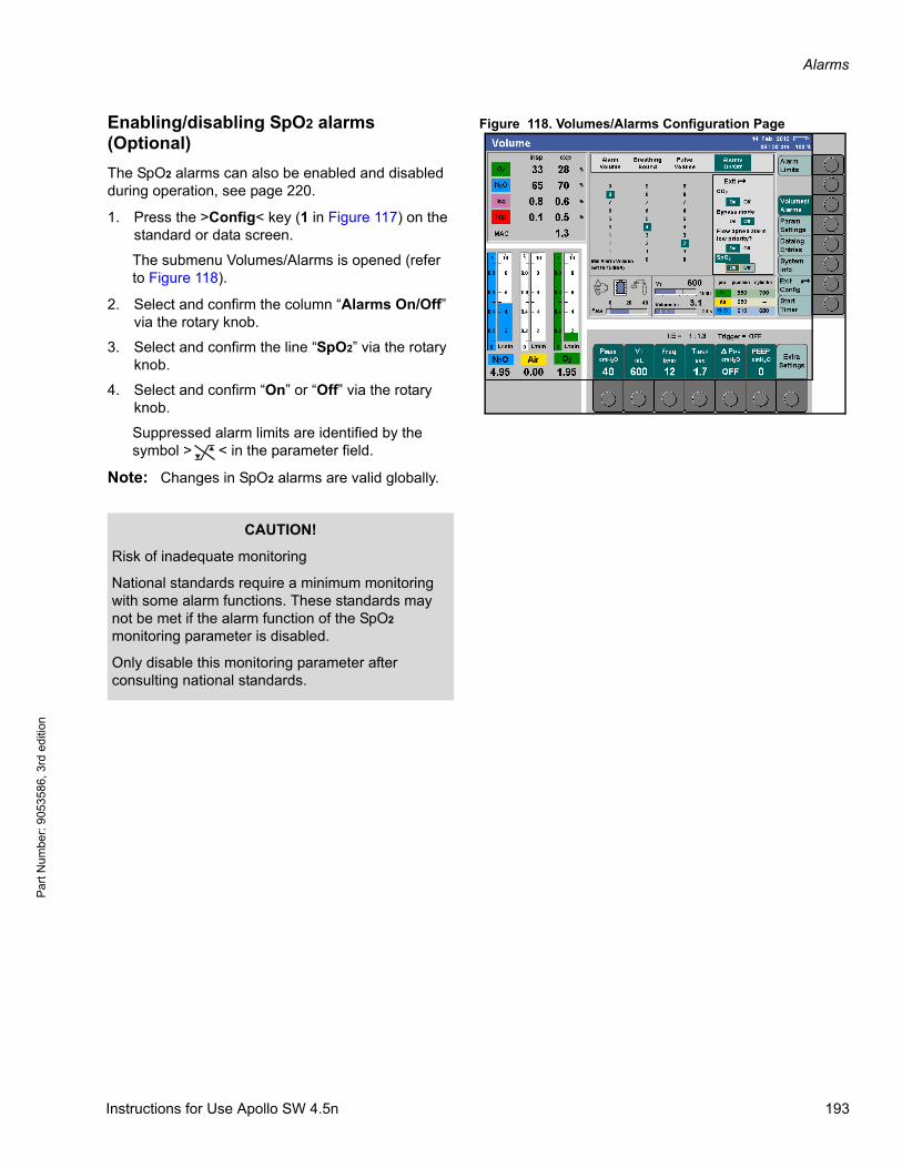
Alarms
Par
t Num
ber:
905
3586
, 3rd
edi
tion
Figure 118. Volumes/Alarms Configuration PageEnabling/disabling SpO2 alarms (Optional)
The SpO2 alarms can also be enabled and disabled during operation, see page 220.
1. Press the >Config< key (1 in Figure 117) on the standard or data screen.
The submenu Volumes/Alarms is opened (refer to Figure 118).
2. Select and confirm the column “Alarms On/Off” via the rotary knob.
3. Select and confirm the line “SpO2” via the rotary knob.
4. Select and confirm “On” or “Off” via the rotary knob.
Suppressed alarm limits are identified by the symbol > < in the parameter field.
Note: Changes in SpO2 alarms are valid globally.
CAUTION!
Risk of inadequate monitoring
National standards require a minimum monitoring with some alarm functions. These standards may not be met if the alarm function of the SpO2 monitoring parameter is disabled.
Only disable this monitoring parameter after consulting national standards.
_
Instructions for Use Apollo SW 4.5n 193
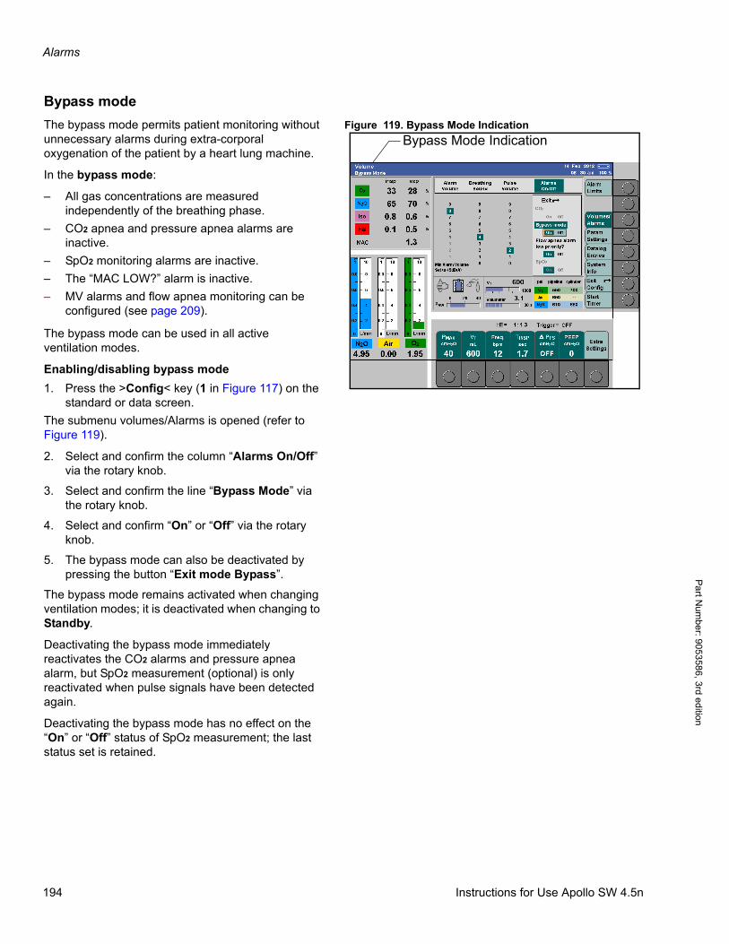
Alarms
Pa
rt Num
ber: 905358
6, 3rd edition
Bypass mode
Figure 119. Bypass Mode IndicationThe bypass mode permits patient monitoring without unnecessary alarms during extra-corporal oxygenation of the patient by a heart lung machine.
In the bypass mode:
– All gas concentrations are measured independently of the breathing phase.
– CO2 apnea and pressure apnea alarms are inactive.
– SpO2 monitoring alarms are inactive.
– The “MAC LOW?” alarm is inactive.
– MV alarms and flow apnea monitoring can be configured (see page 209).
The bypass mode can be used in all active ventilation modes.
Enabling/disabling bypass mode
1. Press the >Config< key (1 in Figure 117) on the standard or data screen.
The submenu volumes/Alarms is opened (refer to Figure 119).
2. Select and confirm the column “Alarms On/Off” via the rotary knob.
3. Select and confirm the line “Bypass Mode” via the rotary knob.
4. Select and confirm “On” or “Off” via the rotary knob.
5. The bypass mode can also be deactivated by pressing the button “Exit mode Bypass”.
The bypass mode remains activated when changing ventilation modes; it is deactivated when changing to Standby.
Deactivating the bypass mode immediately reactivates the CO2 alarms and pressure apnea alarm, but SpO2 measurement (optional) is only reactivated when pulse signals have been detected again.
Deactivating the bypass mode has no effect on the “On” or “Off” status of SpO2 measurement; the last status set is retained.
Bypass Mode Indication
194 Instructions for Use Apollo SW 4.5n
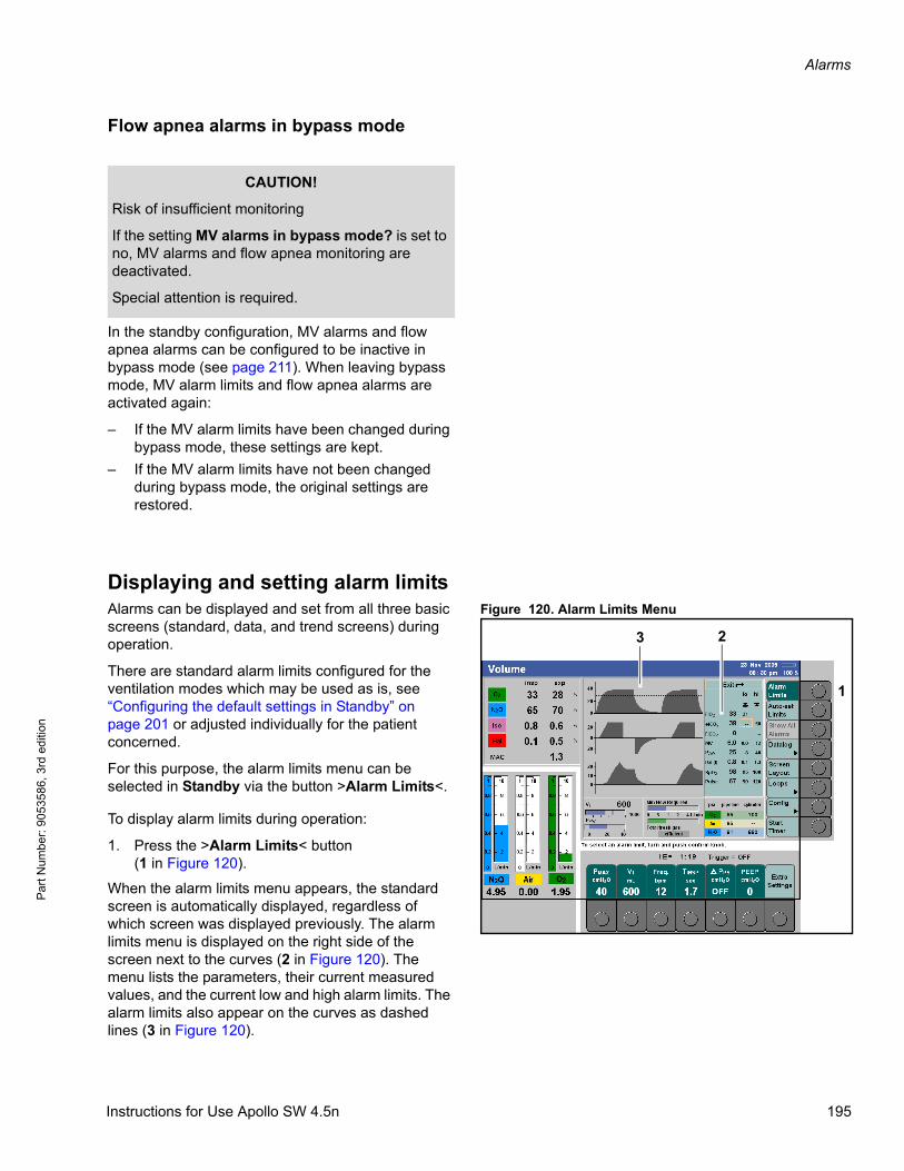
Alarms
Par
t Num
ber:
905
3586
, 3rd
edi
tion
Flow apnea alarms in bypass mode
In the standby configuration, MV alarms and flow apnea alarms can be configured to be inactive in bypass mode (see page 211). When leaving bypass mode, MV alarm limits and flow apnea alarms are activated again:
– If the MV alarm limits have been changed during bypass mode, these settings are kept.
– If the MV alarm limits have not been changed during bypass mode, the original settings are restored.
Displaying and setting alarm limitsFigure 120. Alarm Limits MenuAlarms can be displayed and set from all three basic
screens (standard, data, and trend screens) during operation.
There are standard alarm limits configured for the ventilation modes which may be used as is, see “Configuring the default settings in Standby” on page 201 or adjusted individually for the patient concerned.
For this purpose, the alarm limits menu can be selected in Standby via the button >Alarm Limits<.
To display alarm limits during operation:
1. Press the >Alarm Limits< button(1 in Figure 120).
When the alarm limits menu appears, the standard screen is automatically displayed, regardless of which screen was displayed previously. The alarm limits menu is displayed on the right side of the screen next to the curves (2 in Figure 120). The menu lists the parameters, their current measured values, and the current low and high alarm limits. The alarm limits also appear on the curves as dashed lines (3 in Figure 120).
CAUTION!
Risk of insufficient monitoring
If the setting MV alarms in bypass mode? is set to no, MV alarms and flow apnea monitoring are deactivated.
Special attention is required.
1
23
Instructions for Use Apollo SW 4.5n 195
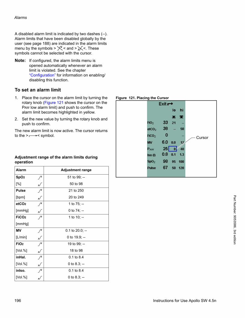
Alarms
Pa
rt Num
ber: 905358
6, 3rd edition
A disabled alarm limit is indicated by two dashes (--). Alarm limits that have been disabled globally by the user (see page 188) are indicated in the alarm limits menu by the symbols > < and > <. These symbols cannot be selected with the cursor.
Note: If configured, the alarm limits menu is opened automatically whenever an alarm limit is violated. See the chapter “Configuration” for information on enabling/disabling this function.
To set an alarm limit
Figure 121. Placing the Cursor1. Place the cursor on the alarm limit by turning the rotary knob (Figure 121 shows the cursor on the PAW low alarm limit) and push to confirm. The alarm limit becomes highlighted in yellow.
2. Set the new value by turning the rotary knob and push to confirm.
The new alarm limit is now active. The cursor returns to the > < symbol.
Adjustment range of the alarm limits duringoperation
> <
Cursor
Alarm Adjustment range
SpO2 51 to 99; --
[%] 50 to 98
Pulse 21 to 250
[bpm] 20 to 249
etCO2 1 to 75; --
[mmHg] 0 to 74; --
FiCO2 1 to 10; --
[mmHg]
MV 0.1 to 20.0; --
[L/min] 0 to 19.9; --
FiO2 19 to 99; --
[Vol.%] 18 to 98
inHal. 0.1 to 8.4
[Vol.%] 0 to 8.3; --
inIso. 0.1 to 8.4
[Vol.%] 0 to 8.3; --
>
<
>
<
>
<
>
>
<
>
<
>
<
>
<
196 Instructions for Use Apollo SW 4.5n
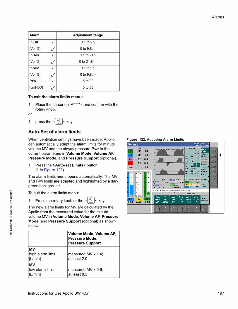
Alarms
Par
t Num
ber:
905
3586
, 3rd
edi
tion
To exit the alarm limits menu:
1. Place the cursor on > < and confirm with the rotary knob.
or
1. press the > < key.
Auto-Set of alarm limits
Figure 122. Adapting Alarm LimitsWhen ventilation settings have been made, Apollo can automatically adapt the alarm limits for minute volume MV and the airway pressure PAW to the current parameters in Volume Mode, Volume AF, Pressure Mode, and Pressure Support (optional).
1. Press the >Auto-set Limits< button(1 in Figure 122).
The alarm limits menu opens automatically. The MV and PAW limits are adapted and highlighted by a dark green background.
To quit the alarm limits menu:
1. Press the rotary knob or the > < key.
The new alarm limits for MV are calculated by the Apollo from the measured value for the minute volume MV in Volume Mode, Volume AF, Pressure Mode, and Pressure Support (optional) as shown below:
inEnf. 0.1 to 9.9
[Vol.%] 0 to 9.8; --
inDes. 0.1 to 21.9
[Vol.%] 0 to 21.8; --
inSev. 0.1 to 9.9
[Vol.%] 0 to 9.8; --
PAW 5 to 99
[cmH2O] 0 to 35
Alarm Adjustment range
>
<
>
<
>
<
>
<
1
Volume Mode, Volume AF,Pressure Mode, Pressure Support
MV high alarm limit[L/min]
measured MV x 1.4;at least 2.0
MV low alarm limit[L/min]
measured MV x 0.6;at least 0.3
Instructions for Use Apollo SW 4.5n 197
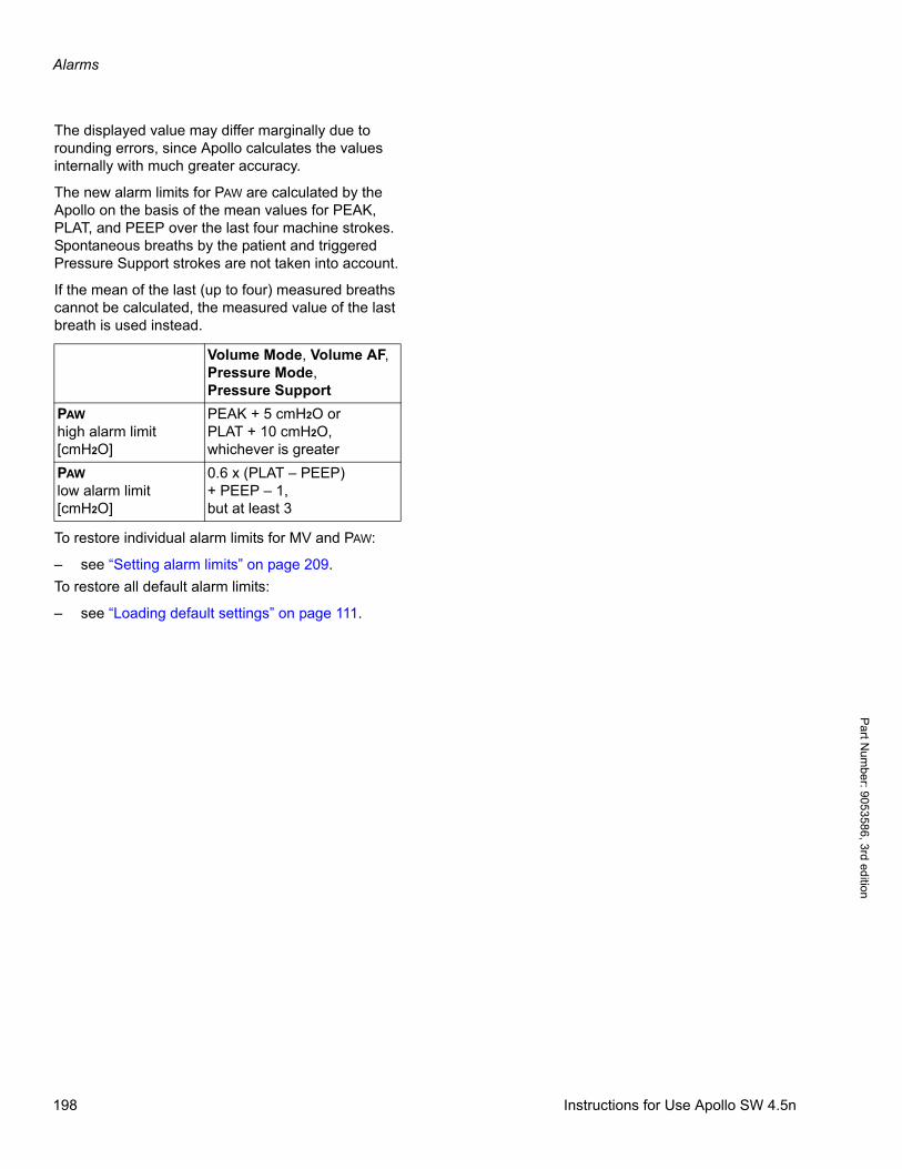
Alarms
Pa
rt Num
ber: 905358
6, 3rd edition
The displayed value may differ marginally due to rounding errors, since Apollo calculates the values internally with much greater accuracy.
The new alarm limits for PAW are calculated by the Apollo on the basis of the mean values for PEAK, PLAT, and PEEP over the last four machine strokes. Spontaneous breaths by the patient and triggered Pressure Support strokes are not taken into account.
If the mean of the last (up to four) measured breaths cannot be calculated, the measured value of the last breath is used instead.
To restore individual alarm limits for MV and PAW:
– see “Setting alarm limits” on page 209.
To restore all default alarm limits:
– see “Loading default settings” on page 111.
Volume Mode, Volume AF,Pressure Mode, Pressure Support
PAW high alarm limit[cmH2O]
PEAK + 5 cmH2O orPLAT + 10 cmH2O,whichever is greater
PAW low alarm limit[cmH2O]
0.6 x (PLAT – PEEP)+ PEEP – 1,but at least 3
198 Instructions for Use Apollo SW 4.5n
Configuration
Par
t Num
ber:
905
3586
, 3rd
edi
tion
Configuration
ContentsOverview . . . . . . . . . . . . . . . . . . . . . . . . . . . . . . . . . . . . . . . . . . . . . . . . . . . . . . . . . . . . . . . . . . . . . . . . . . . . . . 201
Configuring the default settings in Standby . . . . . . . . . . . . . . . . . . . . . . . . . . . . . . . . . . . . . . . . . . . . . . . . . 201
System settings . . . . . . . . . . . . . . . . . . . . . . . . . . . . . . . . . . . . . . . . . . . . . . . . . . . . . . . . . . . . . . . . . . . . . . . . 202
Alarm volume . . . . . . . . . . . . . . . . . . . . . . . . . . . . . . . . . . . . . . . . . . . . . . . . . . . . . . . . . . . . . . . . . . . . . . . . . . . 202
Breathing sound . . . . . . . . . . . . . . . . . . . . . . . . . . . . . . . . . . . . . . . . . . . . . . . . . . . . . . . . . . . . . . . . . . . . . . . . . 203
Pulse volume (for SpO2, optional) . . . . . . . . . . . . . . . . . . . . . . . . . . . . . . . . . . . . . . . . . . . . . . . . . . . . . . . . . . . 204
Date/Time/Language . . . . . . . . . . . . . . . . . . . . . . . . . . . . . . . . . . . . . . . . . . . . . . . . . . . . . . . . . . . . . . . . . . . . . 204
Parameters . . . . . . . . . . . . . . . . . . . . . . . . . . . . . . . . . . . . . . . . . . . . . . . . . . . . . . . . . . . . . . . . . . . . . . . . . . . . 204
Scaling . . . . . . . . . . . . . . . . . . . . . . . . . . . . . . . . . . . . . . . . . . . . . . . . . . . . . . . . . . . . . . . . . . . . . . . . . . . . . . . . 222
Units . . . . . . . . . . . . . . . . . . . . . . . . . . . . . . . . . . . . . . . . . . . . . . . . . . . . . . . . . . . . . . . . . . . . . . . . . . . . . . . . . . 205
Gas monitoring . . . . . . . . . . . . . . . . . . . . . . . . . . . . . . . . . . . . . . . . . . . . . . . . . . . . . . . . . . . . . . . . . . . . . . . . . . 205
Optional parameters . . . . . . . . . . . . . . . . . . . . . . . . . . . . . . . . . . . . . . . . . . . . . . . . . . . . . . . . . . . . . . . . . . . . . . 205
Interfaces datalog . . . . . . . . . . . . . . . . . . . . . . . . . . . . . . . . . . . . . . . . . . . . . . . . . . . . . . . . . . . . . . . . . . . . . . . 206
Datalog entries triggered by . . . . . . . . . . . . . . . . . . . . . . . . . . . . . . . . . . . . . . . . . . . . . . . . . . . . . . . . . . . . . . . . 206
COM PORT 1 MEDIBUS, COM PORT 2 MEDIBUS . . . . . . . . . . . . . . . . . . . . . . . . . . . . . . . . . . . . . . . . . . . . . 206
MEDIBUS default configuration . . . . . . . . . . . . . . . . . . . . . . . . . . . . . . . . . . . . . . . . . . . . . . . . . . . . . . . . . . . . . 207
Screen layout . . . . . . . . . . . . . . . . . . . . . . . . . . . . . . . . . . . . . . . . . . . . . . . . . . . . . . . . . . . . . . . . . . . . . . . . . . 207
Setting alarm limits . . . . . . . . . . . . . . . . . . . . . . . . . . . . . . . . . . . . . . . . . . . . . . . . . . . . . . . . . . . . . . . . . . . . . . 209
Default alarm limits . . . . . . . . . . . . . . . . . . . . . . . . . . . . . . . . . . . . . . . . . . . . . . . . . . . . . . . . . . . . . . . . . . . . . . . 209
Default agent limits . . . . . . . . . . . . . . . . . . . . . . . . . . . . . . . . . . . . . . . . . . . . . . . . . . . . . . . . . . . . . . . . . . . . . . . 210
Alarms in Man/Spont . . . . . . . . . . . . . . . . . . . . . . . . . . . . . . . . . . . . . . . . . . . . . . . . . . . . . . . . . . . . . . . . . . . . . 210
Therapy related . . . . . . . . . . . . . . . . . . . . . . . . . . . . . . . . . . . . . . . . . . . . . . . . . . . . . . . . . . . . . . . . . . . . . . . . . 211
Device related . . . . . . . . . . . . . . . . . . . . . . . . . . . . . . . . . . . . . . . . . . . . . . . . . . . . . . . . . . . . . . . . . . . . . . . . . . . 212
Other . . . . . . . . . . . . . . . . . . . . . . . . . . . . . . . . . . . . . . . . . . . . . . . . . . . . . . . . . . . . . . . . . . . . . . . . . . . . . . . . . . 213
Ventilator and gas supply . . . . . . . . . . . . . . . . . . . . . . . . . . . . . . . . . . . . . . . . . . . . . . . . . . . . . . . . . . . . . . . . 214
Parameter Default Values . . . . . . . . . . . . . . . . . . . . . . . . . . . . . . . . . . . . . . . . . . . . . . . . . . . . . . . . . . . . . . . . . . 214
Gas supply checks . . . . . . . . . . . . . . . . . . . . . . . . . . . . . . . . . . . . . . . . . . . . . . . . . . . . . . . . . . . . . . . . . . . . . . . 215
Ventilator Default Settings . . . . . . . . . . . . . . . . . . . . . . . . . . . . . . . . . . . . . . . . . . . . . . . . . . . . . . . . . . . . . . . . . 215
Body Weight Related Ventilator Settings . . . . . . . . . . . . . . . . . . . . . . . . . . . . . . . . . . . . . . . . . . . . . . . . . . . . . . 217
System information . . . . . . . . . . . . . . . . . . . . . . . . . . . . . . . . . . . . . . . . . . . . . . . . . . . . . . . . . . . . . . . . . . . . . 218
General Information . . . . . . . . . . . . . . . . . . . . . . . . . . . . . . . . . . . . . . . . . . . . . . . . . . . . . . . . . . . . . . . . . . . . . . 218
Activate Option . . . . . . . . . . . . . . . . . . . . . . . . . . . . . . . . . . . . . . . . . . . . . . . . . . . . . . . . . . . . . . . . . . . . . . . . . . 218
Trace 1, Trace 2, Trace 3 . . . . . . . . . . . . . . . . . . . . . . . . . . . . . . . . . . . . . . . . . . . . . . . . . . . . . . . . . . . . . . . . . . 218
Remote Service . . . . . . . . . . . . . . . . . . . . . . . . . . . . . . . . . . . . . . . . . . . . . . . . . . . . . . . . . . . . . . . . . . . . . . . . . 219
Exiting standby configuration . . . . . . . . . . . . . . . . . . . . . . . . . . . . . . . . . . . . . . . . . . . . . . . . . . . . . . . . . . . . . . . 219
Configuration during operation . . . . . . . . . . . . . . . . . . . . . . . . . . . . . . . . . . . . . . . . . . . . . . . . . . . . . . . . . . . 220
Instructions for Use Apollo SW 4.5n 199

Configuration
Pa
rt Num
ber: 905358
6, 3rd edition
Volumes/Alarms . . . . . . . . . . . . . . . . . . . . . . . . . . . . . . . . . . . . . . . . . . . . . . . . . . . . . . . . . . . . . . . . . . . . . . . . . 221
Alarm volume . . . . . . . . . . . . . . . . . . . . . . . . . . . . . . . . . . . . . . . . . . . . . . . . . . . . . . . . . . . . . . . . . . . . . . . . 221
Pulse volume (for SpO2, optional) . . . . . . . . . . . . . . . . . . . . . . . . . . . . . . . . . . . . . . . . . . . . . . . . . . . . . . . . 222
Alarms on/off . . . . . . . . . . . . . . . . . . . . . . . . . . . . . . . . . . . . . . . . . . . . . . . . . . . . . . . . . . . . . . . . . . . . . . . . . 222
Param Settings . . . . . . . . . . . . . . . . . . . . . . . . . . . . . . . . . . . . . . . . . . . . . . . . . . . . . . . . . . . . . . . . . . . . . . . . . . 222
Scaling . . . . . . . . . . . . . . . . . . . . . . . . . . . . . . . . . . . . . . . . . . . . . . . . . . . . . . . . . . . . . . . . . . . . . . . . . . . . . 222
Units . . . . . . . . . . . . . . . . . . . . . . . . . . . . . . . . . . . . . . . . . . . . . . . . . . . . . . . . . . . . . . . . . . . . . . . . . . . . . . . 222
Agent monitoring . . . . . . . . . . . . . . . . . . . . . . . . . . . . . . . . . . . . . . . . . . . . . . . . . . . . . . . . . . . . . . . . . . . . . . 223
Datalog entries . . . . . . . . . . . . . . . . . . . . . . . . . . . . . . . . . . . . . . . . . . . . . . . . . . . . . . . . . . . . . . . . . . . . . . . . . . 223
Datalog entries triggered by . . . . . . . . . . . . . . . . . . . . . . . . . . . . . . . . . . . . . . . . . . . . . . . . . . . . . . . . . . . . . 223
System information . . . . . . . . . . . . . . . . . . . . . . . . . . . . . . . . . . . . . . . . . . . . . . . . . . . . . . . . . . . . . . . . . . . . . . . 223
General information . . . . . . . . . . . . . . . . . . . . . . . . . . . . . . . . . . . . . . . . . . . . . . . . . . . . . . . . . . . . . . . . . . . 223
Trace 1, Trace 2, Trace 3 . . . . . . . . . . . . . . . . . . . . . . . . . . . . . . . . . . . . . . . . . . . . . . . . . . . . . . . . . . . . . . . 223
Exit SysInfo . . . . . . . . . . . . . . . . . . . . . . . . . . . . . . . . . . . . . . . . . . . . . . . . . . . . . . . . . . . . . . . . . . . . . . . . . . 224
Exiting configuration during operation . . . . . . . . . . . . . . . . . . . . . . . . . . . . . . . . . . . . . . . . . . . . . . . . . . . . . . . . . 224
Setting the patient’s age and weight during operation . . . . . . . . . . . . . . . . . . . . . . . . . . . . . . . . . . . . . . . . . . . . 224
200 Instructions for Use Apollo SW 4.5n
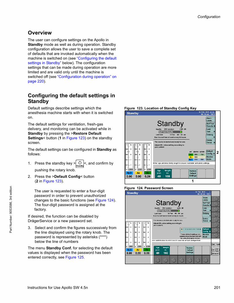
Configuration
Par
t Num
ber:
905
3586
, 3rd
edi
tion
OverviewThe user can configure settings on the Apollo in Standby mode as well as during operation. Standby configuration allows the user to save a complete set of defaults that are invoked automatically when the machine is switched on (see “Configuring the default settings in Standby” below). The configuration settings that can be made during operation are more limited and are valid only until the machine is switched off (see “Configuration during operation” on page 220).
Configuring the default settings in Standby
Figure 123. Location of Standby Config KeyDefault settings describe settings which the anesthesia machine starts with when it is switched on.
The default settings for ventilation, fresh-gas delivery, and monitoring can be activated while in Standby by pressing the >Restore Default Settings< button (1 in Figure 123) on the standby screen.
The default settings can be configured in Standby as follows:
1. Press the standby key > <, and confirm by
pushing the rotary knob.
2. Press the >Default Config< button(2 in Figure 123).
Figure 124. Password ScreenThe user is requested to enter a four-digit password in order to prevent unauthorized changes to the basic functions (see Figure 124). The four-digit password is assigned at the factory.
If desired, the function can be disabled by DrägerService or a new password set.
3. Select and confirm the figures successively from the line displayed using the rotary knob. The password is represented by asterisks (****) below the line of numbers
The menu Standby Conf. for selecting the default values is displayed when the password has been entered correctly, see Figure 125.
1
2
Instructions for Use Apollo SW 4.5n 201

Configuration
Pa
rt Num
ber: 905358
6, 3rd edition
Default settings are selected in the same way as described in the chapter “User Interface”:
– Active buttons appear in dark green.
– The current settings are highlighted dark green.
– Settings are selected by pressing the rotary knob and will be highlighted in yellow: these values can be adjusted using the rotary knob.
– The exit arrow > < is used to exit the menu or to return the user to the preceding level.
Figure 125. System Settings Standby Conf. Screen
The following settings can be selected via the vertical buttons, see Figure 125.:
– System Settings
– Parameters
– Interfaces Datalog
– Screen Layout
– Alarm Limits
– Ventilator and gas supply
– System Info
A dark green key indicated which screen is currently active. Light green keys indicate which screens are available for selection. Each configuration screen is described in the following paragraphs.
Exiting the standby configuration:
1. Press the button >Exit < or key > < or
> <.
System settingsThe following settings can be selected in the System Settings standby configuration screen:
Alarm volume
See 1 in Figure 125.
The minimum alarm volume can be set to a value between 1 to 9. The standard alarm volume cannot be set below this limit.
1 2 3 4
202 Instructions for Use Apollo SW 4.5n
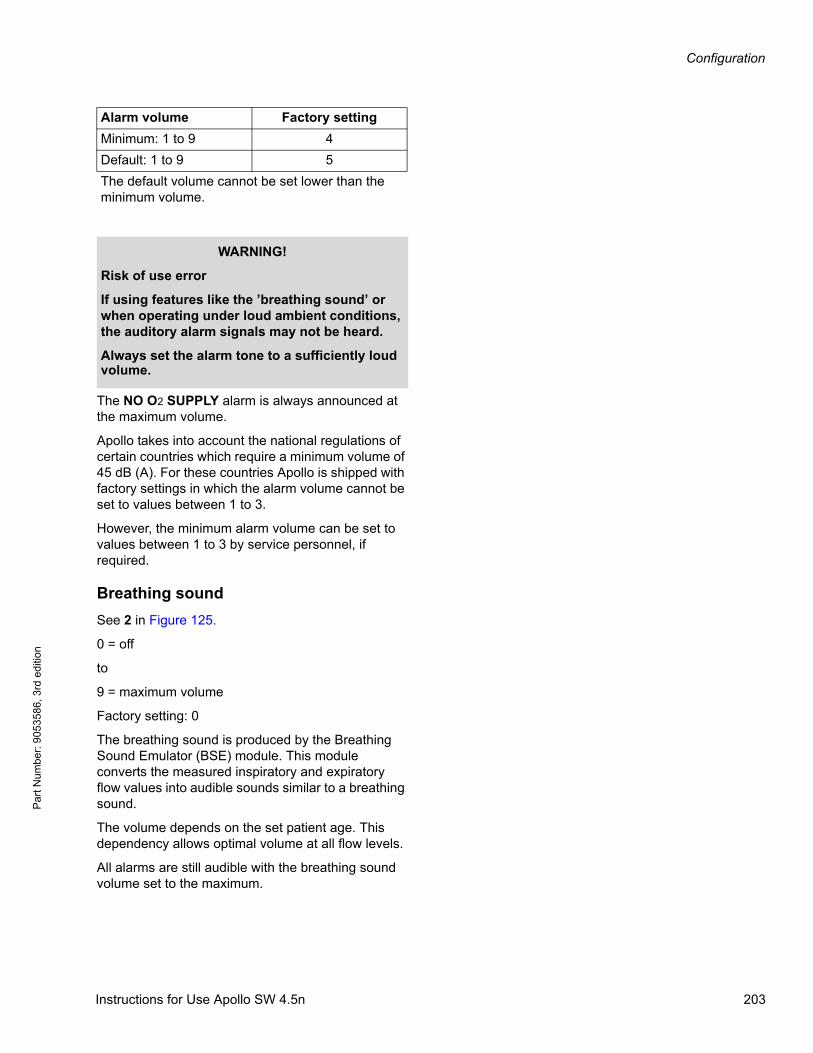
Configuration
Par
t Num
ber:
905
3586
, 3rd
edi
tion
The NO O2 SUPPLY alarm is always announced at the maximum volume.
Apollo takes into account the national regulations of certain countries which require a minimum volume of 45 dB (A). For these countries Apollo is shipped with factory settings in which the alarm volume cannot be set to values between 1 to 3.
However, the minimum alarm volume can be set to values between 1 to 3 by service personnel, if required.
Breathing sound
See 2 in Figure 125.
0 = off
to
9 = maximum volume
Factory setting: 0
The breathing sound is produced by the Breathing Sound Emulator (BSE) module. This module converts the measured inspiratory and expiratory flow values into audible sounds similar to a breathing sound.
The volume depends on the set patient age. This dependency allows optimal volume at all flow levels.
All alarms are still audible with the breathing sound volume set to the maximum.
Alarm volume Factory setting
Minimum: 1 to 9 4
Default: 1 to 9 5
The default volume cannot be set lower than the minimum volume.
WARNING!
Risk of use error
If using features like the ’breathing sound’ or when operating under loud ambient conditions, the auditory alarm signals may not be heard.
Always set the alarm tone to a sufficiently loud volume.
Instructions for Use Apollo SW 4.5n 203
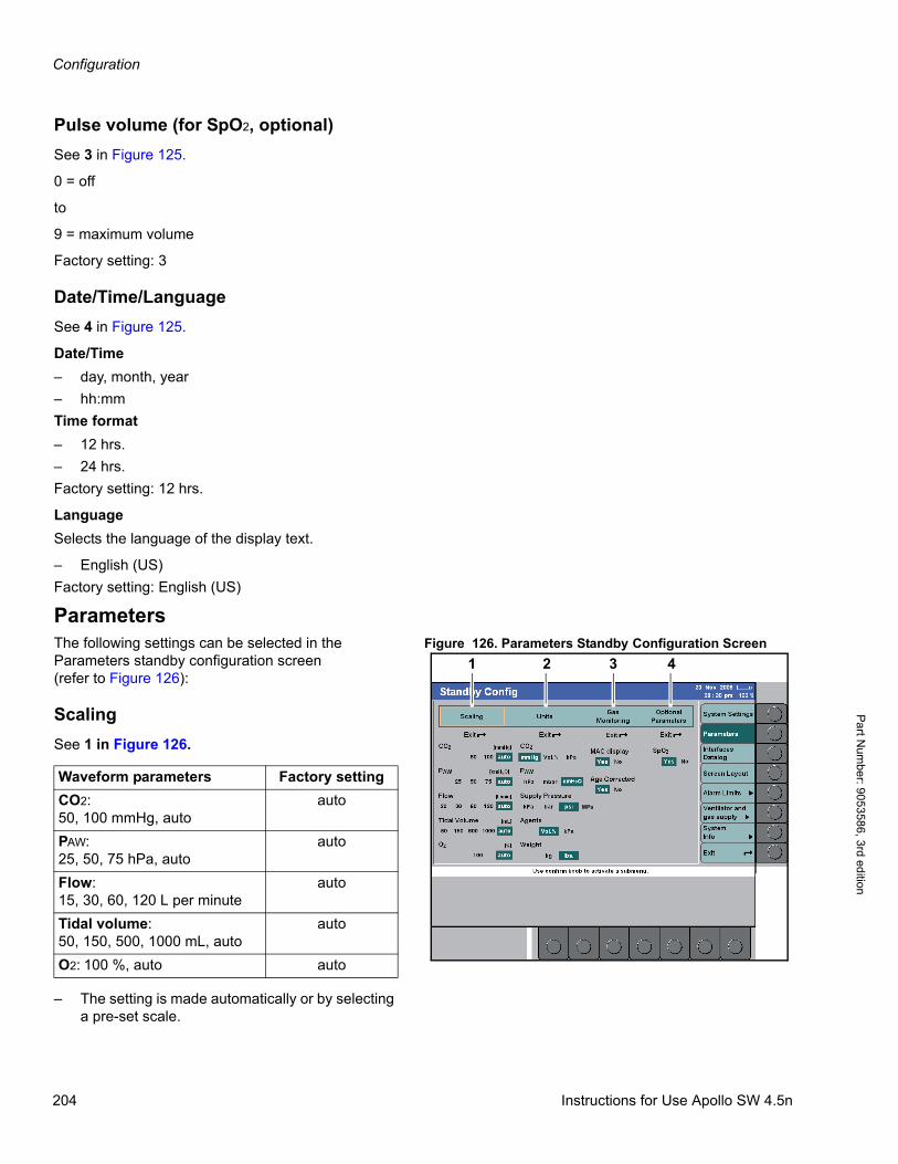
Configuration
Pa
rt Num
ber: 905358
6, 3rd edition
Pulse volume (for SpO2, optional)
See 3 in Figure 125.
0 = off
to
9 = maximum volume
Factory setting: 3
Date/Time/Language
See 4 in Figure 125.
Date/Time
– day, month, year
– hh:mm
Time format
– 12 hrs.
– 24 hrs.
Factory setting: 12 hrs.
Language
Selects the language of the display text.
– English (US)
Factory setting: English (US)
ParametersFigure 126. Parameters Standby Configuration ScreenThe following settings can be selected in the
Parameters standby configuration screen(refer to Figure 126):
Scaling
See 1 in Figure 126.
– The setting is made automatically or by selecting a pre-set scale.
MPa
1 2 3 4
Waveform parameters Factory setting
CO2: 50, 100 mmHg, auto
auto
PAW: 25, 50, 75 hPa, auto
auto
Flow: 15, 30, 60, 120 L per minute
auto
Tidal volume:50, 150, 500, 1000 mL, auto
auto
O2: 100 %, auto auto
204 Instructions for Use Apollo SW 4.5n
Configuration
Par
t Num
ber:
905
3586
, 3rd
edi
tion
– Tidal Volume
auto: A suitable scale is selected automatically in accordance with the set age:
– <1 year: 50 mL
– 1 to 2 years: 150 mL
– >2 years to 10 years: 500 mL
– >10 years: 1000 mL
Units
See 2 in Figure 126.
Gas monitoring
See 3 in Figure 126.
Optional parameters
See 4 in Figure 126.
Units Factory setting
CO2: mmHg, Vol%, kPa mmHg
PAW: hPa, mbar, cmH2O cmH2O
supply pressure: kPa, MPa, bar, psi
psi
agents: Vol%, kPa Vol%
weight: kg, lbs. lbs.
Parameter Factory setting
MAC display: yes/no yes
Age corrected: yes/no yes
See page 166 for a detailed description of the MAC definition and calculation.
Parameter Factory setting
SpO2: yes/no Automatic settingOption available: yesOption not available: no
For a detailed description of SpO2 monitoring, see page 178.
Instructions for Use Apollo SW 4.5n 205
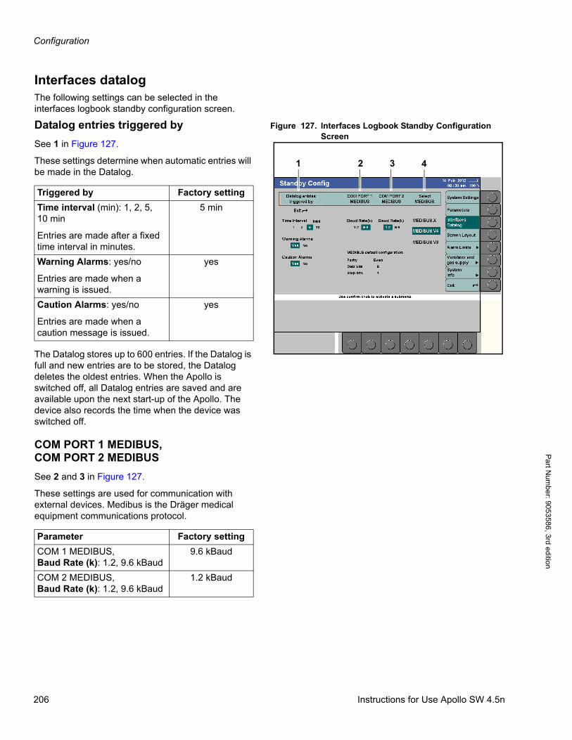
Configuration
Pa
rt Num
ber: 905358
6, 3rd edition
Interfaces datalogThe following settings can be selected in the interfaces logbook standby configuration screen.
Figure 127. Interfaces Logbook Standby Configuration Screen
Datalog entries triggered by
See 1 in Figure 127.
These settings determine when automatic entries will be made in the Datalog.
The Datalog stores up to 600 entries. If the Datalog is full and new entries are to be stored, the Datalog deletes the oldest entries. When the Apollo is switched off, all Datalog entries are saved and are available upon the next start-up of the Apollo. The device also records the time when the device was switched off.
COM PORT 1 MEDIBUS,COM PORT 2 MEDIBUS
See 2 and 3 in Figure 127.
These settings are used for communication with external devices. Medibus is the Dräger medical equipment communications protocol.
1 2 3 4
Triggered by Factory setting
Time interval (min): 1, 2, 5, 10 min
Entries are made after a fixed time interval in minutes.
5 min
Warning Alarms: yes/no
Entries are made when a warning is issued.
yes
Caution Alarms: yes/no
Entries are made when a caution message is issued.
yes
Parameter Factory setting
COM 1 MEDIBUS, Baud Rate (k): 1.2, 9.6 kBaud
9.6 kBaud
COM 2 MEDIBUS, Baud Rate (k): 1.2, 9.6 kBaud
1.2 kBaud
206 Instructions for Use Apollo SW 4.5n

Configuration
Par
t Num
ber:
905
3586
, 3rd
edi
tion
See 4 in Figure 127.
These setting select the MEDIBUS communication protocols:
For detailed information on MEDIBUS.X, MEDIBUS V4 and MEDIBUS V3, refer to the specific Instructions for Use (9037426 and 9052608).
The interfaces can be adapted in line with the equipment to be connected.
MEDIBUS default configuration
– Parity, data bits, and stop bits
These values cannot be configured; this is information only.
Screen layoutFigure 128. Screen Layout Standby Configuration ScreenThe menu screen layout contains three default
layouts of the home screen: Layout 1, Layout 2, and Layout 3.
The layouts comprising the following elements which can be freely configured:
– Three curves with the associated numerical modules (1 in Figure 128).The available curves are displayed when a curve module is selected (1 in Figure 129).
– Three modules which may be assigned to parameters or status displays (2 in Figure 128).The available modules are displayed when a module is selected (1 in Figure 129).
Each curve/module can also be configured as being blank.
Parameter Factory setting
MEDIBUS V3, MEDIBUS V4, MEDIBUS.X
MEDIBUS V4
1
2
Instructions for Use Apollo SW 4.5n 207
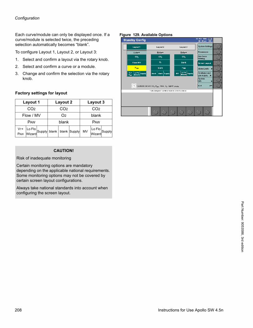
Configuration
Pa
rt Num
ber: 905358
6, 3rd edition
Figure 129. Available OptionsEach curve/module can only be displayed once. If a curve/module is selected twice, the preceding selection automatically becomes “blank”.
To configure Layout 1, Layout 2, or Layout 3:
1. Select and confirm a layout via the rotary knob.
2. Select and confirm a curve or a module.
3. Change and confirm the selection via the rotary knob.
Factory settings for layout
1
Layout 1 Layout 2 Layout 3
CO2 CO2 CO2
Flow / MV O2 blank
PAW blank PAW
VT+
PAW
Lo Flo
WizardSupply blank blank Supply MV
Lo Flo
WizardSupply
CAUTION!
Risk of inadequate monitoring
Certain monitoring options are mandatory depending on the applicable national requirements. Some monitoring options may not be covered by certain screen layout configurations.
Always take national standards into account when configuring the screen layout.
208 Instructions for Use Apollo SW 4.5n
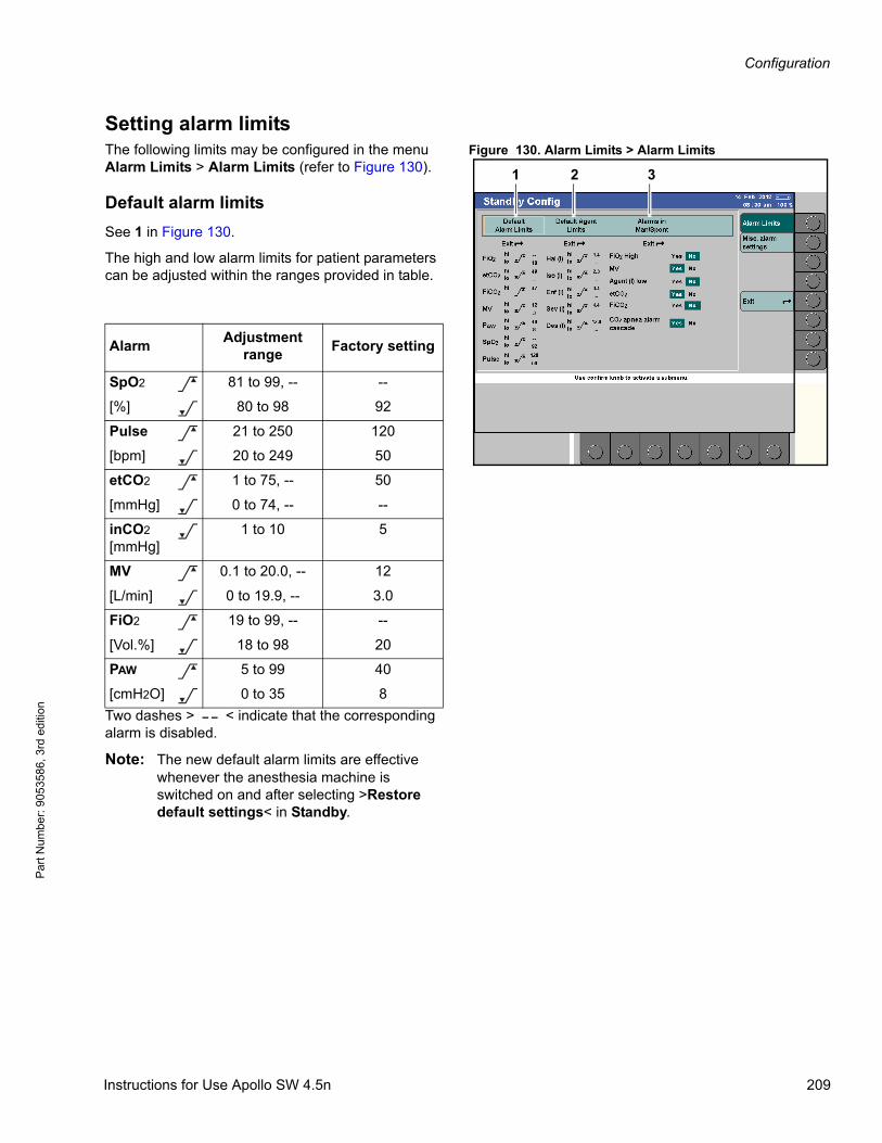
Configuration
Par
t Num
ber:
905
3586
, 3rd
edi
tion
Setting alarm limitsFigure 130. Alarm Limits > Alarm LimitsThe following limits may be configured in the menu
Alarm Limits > Alarm Limits (refer to Figure 130).
Default alarm limits
See 1 in Figure 130.
The high and low alarm limits for patient parameters can be adjusted within the ranges provided in table.
Two dashes > < indicate that the corresponding alarm is disabled.
Note: The new default alarm limits are effective whenever the anesthesia machine is switched on and after selecting >Restore default settings< in Standby.
1 2 3
AlarmAdjustment
rangeFactory setting
SpO2 81 to 99, -- --
[%] 80 to 98 92
Pulse 21 to 250 120
[bpm] 20 to 249 50
etCO2 1 to 75, -- 50
[mmHg] 0 to 74, -- --
inCO2
[mmHg]1 to 10 5
MV 0.1 to 20.0, -- 12
[L/min] 0 to 19.9, -- 3.0
FiO2 19 to 99, -- --
[Vol.%] 18 to 98 20
PAW 5 to 99 40
[cmH2O] 0 to 35 8
>
<
>
<
>
<
<
>
<
>
<
>
<
Instructions for Use Apollo SW 4.5n 209
Configuration
Pa
rt Num
ber: 905358
6, 3rd edition
Default agent limits
See 2 in Figure 130.
The high and low alarm limits for agent can be adjusted within the ranges provided in table.
Two dashes > < indicate that the corresponding alarm is disabled.
Note: The new default alarm limits are effective whenever the anesthesia machine is switched on and after selecting >Restore default settings< in Standby.
Alarms in Man/Spont
See 3 in Figure 130.
These alarms can be activated or deactivated in Standby for switching to Man/Spont When the alarm limits are set to >Yes<, the value is adopted from the automatic ventilation mode. For further information, see “Troubleshooting” on page 257.
AlarmAdjustment
rangeFactory setting
inHal. 0.1 to 8.4 1.5
[Vol.%] 0 to 8.3, -- --
inIso. 0.1 to 8.4 2.3
[Vol.%] 0 to 8.3, -- --
inEnf. 0.1 to 9.9 3.4
[Vol.%] 0 to 9.8, -- --
inDes. 0.1 to 21.9 12.0
[Vol.%] 0 to 21.8, -- --
inSev. 0.1 to 9.9 4.2
[Vol.%] 0 to 9.8, -- --
Alarm Factory setting
FiO2 High: Yes/No No
MV: Yes/No Yes
Agent (I) low: Yes/No No
etCO2: Yes/No Yes
FiCO2: Yes/No No
CO2 apnea alarm cascade: Yes/No
Yes
>
<
>
<
>
<
>
<
>
<
210 Instructions for Use Apollo SW 4.5n
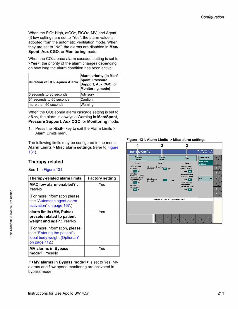
Configuration
Par
t Num
ber:
905
3586
, 3rd
edi
tion
When the FiO2 High, etCO2, FiCO2, MV, and Agent (I) low settings are set to “Yes”, the alarm value is adopted from the automatic ventilation mode. When they are set to “No”, the alarms are disabled in Man/Spont, Aux CGO, or Monitoring mode.
When the CO2 apnea alarm cascade setting is set to >Yes<, the priority of the alarm changes depending on how long the alarm condition has been active:
When the CO2 apnea alarm cascade setting is set to >No<, the alarm is always a Warning in Man/Spont, Pressure Support, Aux CGO, or Monitoring mode.
1. Press the >Exit< key to exit the Alarm Limits > Alarm Limits menu.
Figure 131. Alarm Limits > Misc alarm settingsThe following limits may be configured in the menu Alarm Limits > Misc alarm settings (refer to Figure 131).
Therapy related
See 1 in Figure 131.
If >MV alarms in Bypass mode?< is set to Yes, MV alarms and flow apnea monitoring are activated in bypass mode.
Duration of CO2 Apnea Alarm
Alarm priority (in Man/Spont, Pressure Support, Aux CGO, or Monitoring mode)
0 seconds to 30 seconds Advisory
31 seconds to 60 seconds Caution
more than 60 seconds Warning
1 32
Therapy-related alarm limits Factory setting
MAC low alarm enabled? : Yes/No
(For more information please see “Automatic agent alarm activation” on page 167.)
Yes
alarm limits (MV, Pulse) presets related to patient weight and age? : Yes/No
(For more information, please see “Entering the patient’s ideal body weight (Optional)” on page 112.)
Yes
MV alarms in Bypass mode? : Yes/No
Yes
Instructions for Use Apollo SW 4.5n 211
Configuration
Pa
rt Num
ber: 905358
6, 3rd edition
If set to No, MV alarms and flow apnea monitoring are deactivated in bypass mode.
Device related
See 2 in Figure 131.
CAUTION!
Risk of insufficient monitoring
If the setting MV alarms in Bypass mode? is set to no, MV alarms and flow apnea monitoring are deactivated.
Special attention is required.
Device-related alarm limits Factory setting
O2 cylinder low alarm active at: – –1), 150 to 450
Determine the pressure at which the warning O2 CYLIND. LOW is to be issued. This menu item only appears if the O2 cylinder has been configured as gas supply, see page 215
1) The function is disabled.
450 psi
CO2 absorber time limit:1 to 60 days; – –1)
Determine the operating time interval for the soda lime. As soon as the interval has expired the advisory message CO2 ABSORB. DEPLETED? will be issued.
7 days
212 Instructions for Use Apollo SW 4.5n
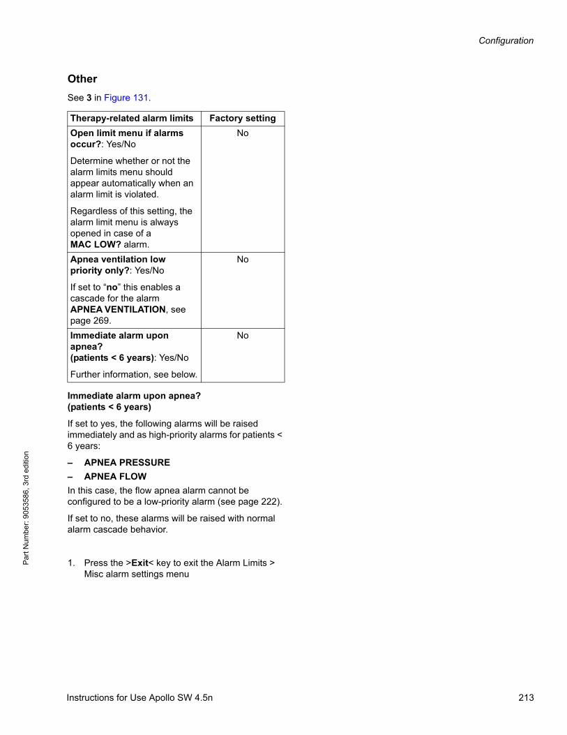
Configuration
Par
t Num
ber:
905
3586
, 3rd
edi
tion
Other
See 3 in Figure 131.
Immediate alarm upon apnea? (patients < 6 years)
If set to yes, the following alarms will be raised immediately and as high-priority alarms for patients < 6 years:
– APNEA PRESSURE
– APNEA FLOW
In this case, the flow apnea alarm cannot be configured to be a low-priority alarm (see page 222).
If set to no, these alarms will be raised with normal alarm cascade behavior.
1. Press the >Exit< key to exit the Alarm Limits > Misc alarm settings menu
Therapy-related alarm limits Factory setting
Open limit menu if alarms occur?: Yes/No
Determine whether or not the alarm limits menu should appear automatically when an alarm limit is violated.
Regardless of this setting, the alarm limit menu is always opened in case of a MAC LOW? alarm.
No
Apnea ventilation low priority only?: Yes/No
If set to “no” this enables a cascade for the alarm APNEA VENTILATION, see page 269.
No
Immediate alarm upon apnea? (patients < 6 years): Yes/No
Further information, see below.
No
Instructions for Use Apollo SW 4.5n 213
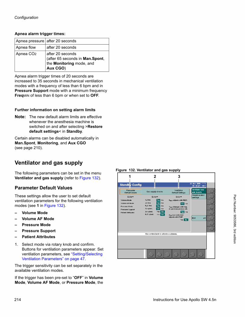
Configuration
Pa
rt Num
ber: 905358
6, 3rd edition
Apnea alarm trigger times:
Apnea alarm trigger times of 20 seconds are increased to 35 seconds in mechanical ventilation modes with a frequency of less than 6 bpm and in Pressure Support mode with a minimum frequency FreqMIN of less than 6 bpm or when set to OFF.
Further information on setting alarm limits
Note: The new default alarm limits are effective whenever the anesthesia machine is switched on and after selecting >Restore default settings< in Standby.
Certain alarms can be disabled automatically in Man.Spont, Monitoring, and Aux CGO(see page 210).
Ventilator and gas supplyFigure 132. Ventilator and gas supply
The following parameters can be set in the menu Ventilator and gas supply (refer to Figure 132).
Parameter Default Values
These settings allow the user to set default ventilation parameters for the following ventilation modes (see 1 in Figure 132).
– Volume Mode
– Volume AF Mode
– Pressure Mode
– Pressure Support
– Patient Attributes
1. Select mode via rotary knob and confirm. Buttons for ventilation parameters appear. Set ventilation parameters, see “Setting/Selecting Ventilation Parameters” on page 47.
The trigger sensitivity can be set separately in the available ventilation modes.
If the trigger has been pre-set to “OFF” in Volume Mode, Volume AF Mode, or Pressure Mode, the
Apnea pressure after 20 seconds
Apnea flow after 20 seconds
Apnea CO2 after 20 seconds(after 65 seconds in Man.Spont, the Monitoring mode, and Aux CGO)
1 2 3
214 Instructions for Use Apollo SW 4.5n
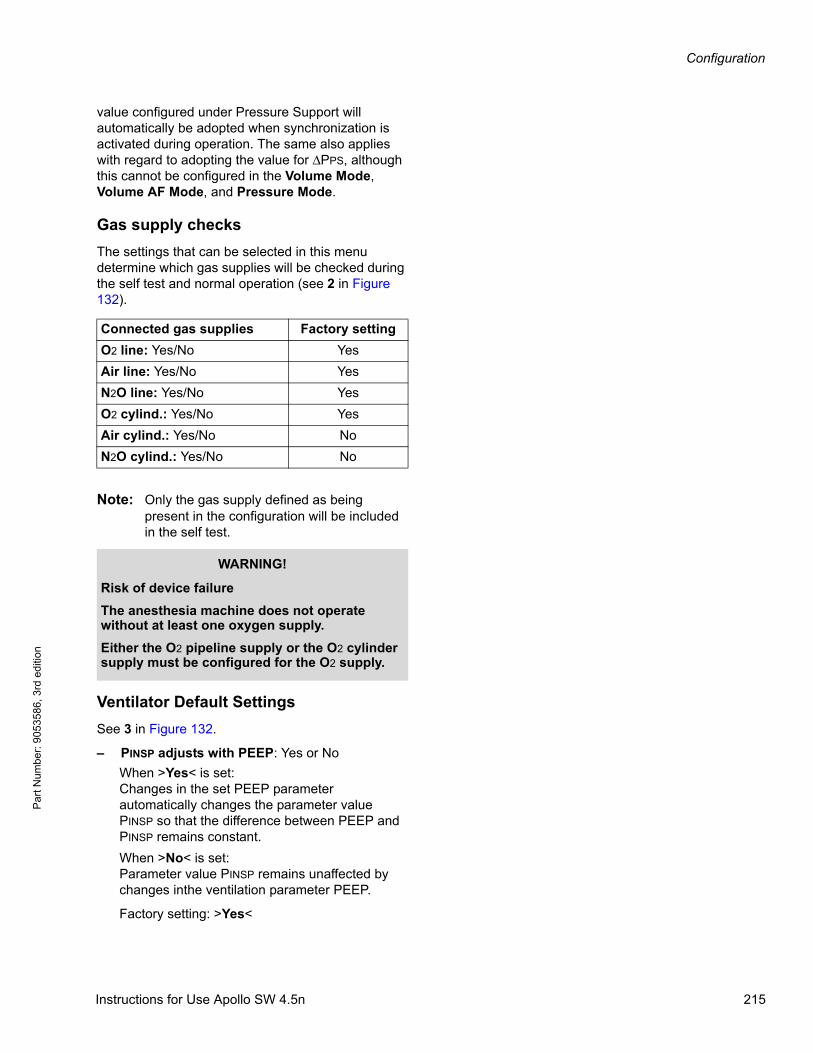
Configuration
Par
t Num
ber:
905
3586
, 3rd
edi
tion
value configured under Pressure Support will automatically be adopted when synchronization is activated during operation. The same also applies with regard to adopting the value for ΔPPS, although this cannot be configured in the Volume Mode, Volume AF Mode, and Pressure Mode.
Gas supply checks
The settings that can be selected in this menu determine which gas supplies will be checked during the self test and normal operation (see 2 in Figure 132).
Note: Only the gas supply defined as being present in the configuration will be included in the self test.
Ventilator Default Settings
See 3 in Figure 132.
– PINSP adjusts with PEEP: Yes or No
When >Yes< is set:Changes in the set PEEP parameter automatically changes the parameter value PINSP so that the difference between PEEP and PINSP remains constant.
When >No< is set:Parameter value PINSP remains unaffected by changes inthe ventilation parameter PEEP.
Factory setting: >Yes<
Connected gas supplies Factory setting
O2 line: Yes/No Yes
Air line: Yes/No Yes
N2O line: Yes/No Yes
O2 cylind.: Yes/No Yes
Air cylind.: Yes/No No
N2O cylind.: Yes/No No
WARNING!
Risk of device failure
The anesthesia machine does not operate without at least one oxygen supply.
Either the O2 pipeline supply or the O2 cylinder supply must be configured for the O2 supply.
Instructions for Use Apollo SW 4.5n 215

Configuration
Pa
rt Num
ber: 905358
6, 3rd edition
– TINSP changes with Freq. if synchronization is off: Yes or No
When >Yes< is set:TINSP is automatically adjusted when the frequency is changed so that the ratio of inspiration to expiration I:E remains constant. This only applies if synchronization has not been set.
When >No< is set:TINSP remains independent of the change in frequency and the ratio of inspiration to expiration I:E changes accordingly.
Factory setting: >Yes<
– PAW low alarm limit adjusts with PEEP: Yes or No
When >Yes< is set:The low alarm limit for airway pressure (PAW) will be automatically changed when the PEEP value is changed.
When >No< is set:The low alarm limit for airway pressure (PAW) will be unaffected by changes in the PEEP value.
In the Pressure Mode, the PAW low alarm limit will not exceed the PINSP - 2. This is also true for changes to PINSP.
In the Pressure Support Mode, PEEP + ΔPPS - 2 will not be exceeded. This is also true for changes to ΔPPS.
Factory setting: >No<
216 Instructions for Use Apollo SW 4.5n
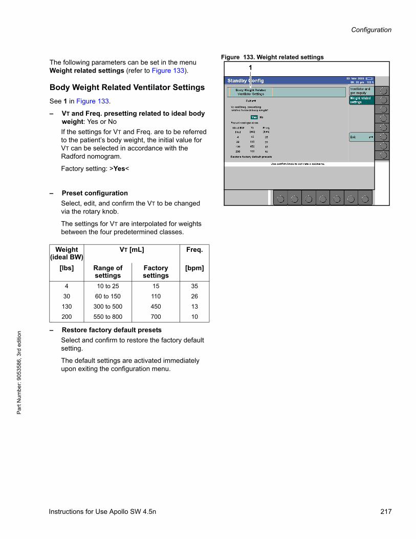
Configuration
Par
t Num
ber:
905
3586
, 3rd
edi
tion
Figure 133. Weight related settingsThe following parameters can be set in the menu Weight related settings (refer to Figure 133).
Body Weight Related Ventilator Settings
See 1 in Figure 133.
– VT and Freq. presetting related to ideal body weight: Yes or No
If the settings for VT and Freq. are to be referred to the patient’s body weight, the initial value for VT can be selected in accordance with the Radford nomogram.
Factory setting: >Yes<
– Preset configuration
Select, edit, and confirm the VT to be changed via the rotary knob.
The settings for VT are interpolated for weights between the four predetermined classes.
– Restore factory default presets
Select and confirm to restore the factory default setting.
The default settings are activated immediately upon exiting the configuration menu.
1
Weight(ideal BW)
VT [mL] Freq.
[lbs] Range ofsettings
Factorysettings
[bpm]
4 10 to 25 15 35
30 60 to 150 110 26
130 300 to 500 450 13
200 550 to 800 700 10
Instructions for Use Apollo SW 4.5n 217
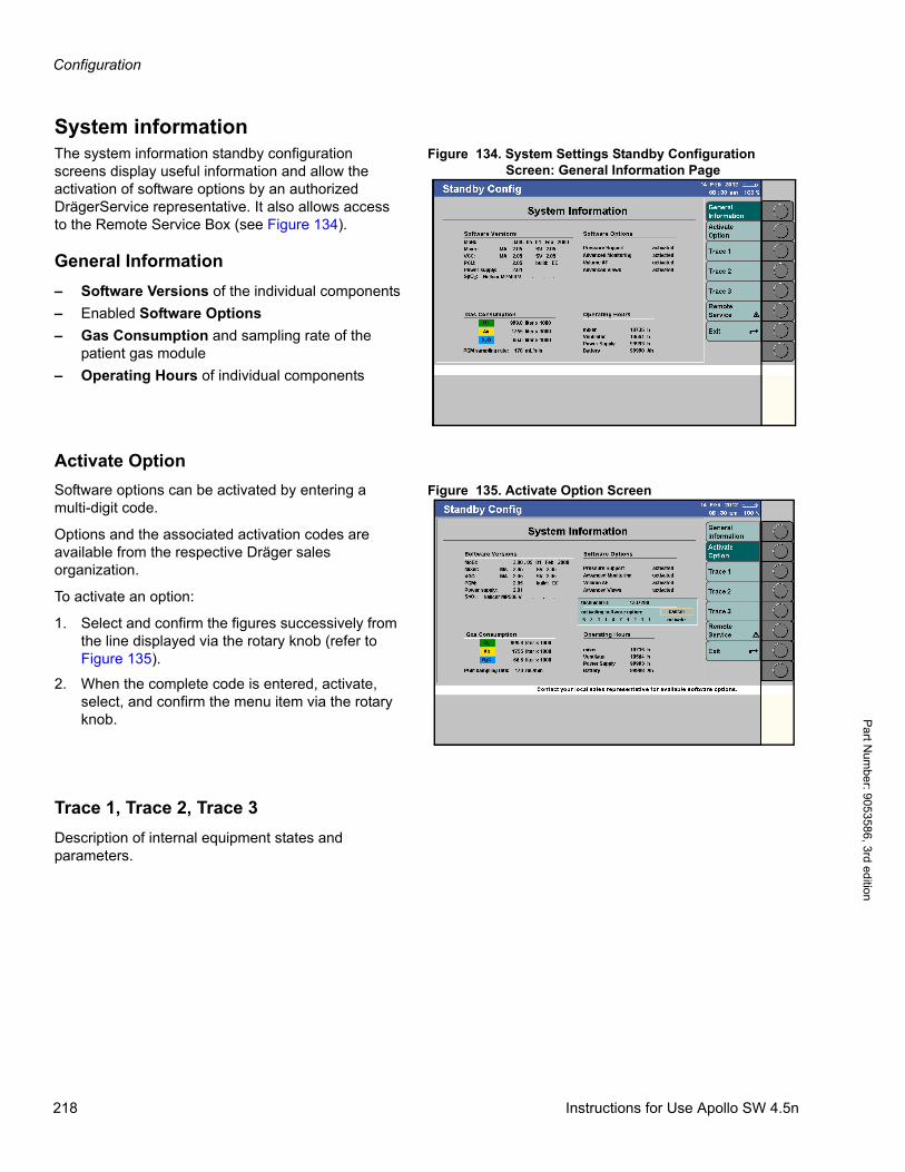
Configuration
Pa
rt Num
ber: 905358
6, 3rd edition
System informationFigure 134. System Settings Standby Configuration
Screen: General Information PageThe system information standby configuration screens display useful information and allow the activation of software options by an authorized DrägerService representative. It also allows access to the Remote Service Box (see Figure 134).
General Information
– Software Versions of the individual components
– Enabled Software Options
– Gas Consumption and sampling rate of the patient gas module
– Operating Hours of individual components
Activate Option
Figure 135. Activate Option ScreenSoftware options can be activated by entering a multi-digit code.
Options and the associated activation codes are available from the respective Dräger sales organization.
To activate an option:
1. Select and confirm the figures successively from the line displayed via the rotary knob (refer to Figure 135).
2. When the complete code is entered, activate, select, and confirm the menu item via the rotary knob.
Trace 1, Trace 2, Trace 3
Description of internal equipment states and parameters.
218 Instructions for Use Apollo SW 4.5n
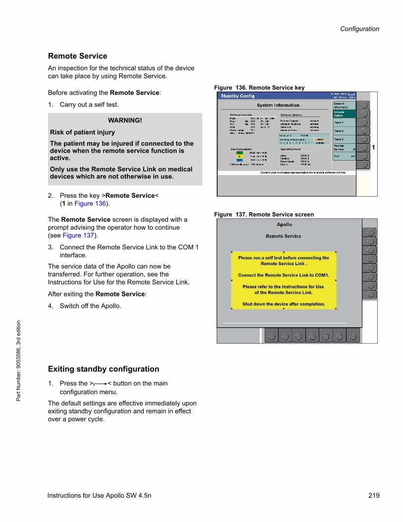
Configuration
Par
t Num
ber:
905
3586
, 3rd
edi
tion
Remote Service
An inspection for the technical status of the device can take place by using Remote Service.
Figure 136. Remote Service keyBefore activating the Remote Service:
1. Carry out a self test.
2. Press the key >Remote Service<(1 in Figure 136).
Figure 137. Remote Service screenThe Remote Service screen is displayed with a prompt advising the operator how to continue(see Figure 137).
3. Connect the Remote Service Link to the COM 1 interface.
The service data of the Apollo can now be transferred. For further operation, see the Instructions for Use for the Remote Service Link.
After exiting the Remote Service:
4. Switch off the Apollo.
Exiting standby configuration
1. Press the > < button on the main configuration menu.
The default settings are effective immediately upon exiting standby configuration and remain in effect over a power cycle.
1
WARNING!
Risk of patient injury
The patient may be injured if connected to the device when the remote service function is active.
Only use the Remote Service Link on medical devices which are not otherwise in use.
Instructions for Use Apollo SW 4.5n 219
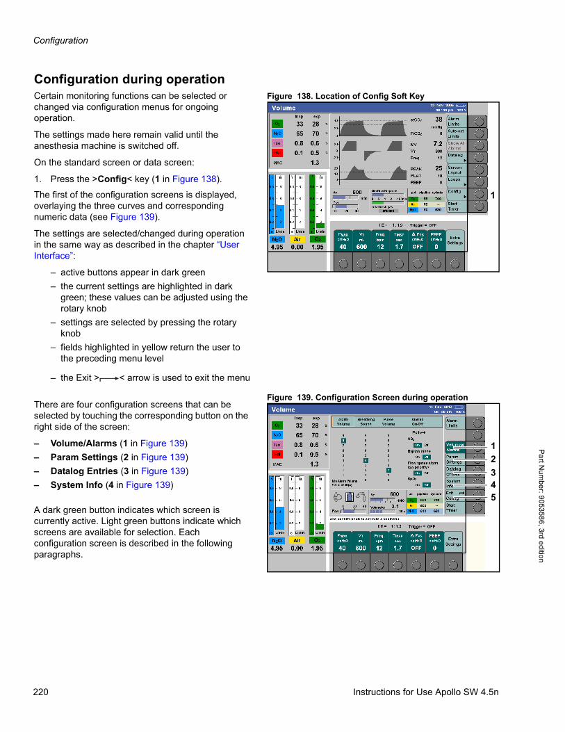
Configuration
Pa
rt Num
ber: 905358
6, 3rd edition
Configuration during operationFigure 138. Location of Config Soft KeyCertain monitoring functions can be selected or
changed via configuration menus for ongoing operation.
The settings made here remain valid until the anesthesia machine is switched off.
On the standard screen or data screen:
1. Press the >Config< key (1 in Figure 138).
The first of the configuration screens is displayed, overlaying the three curves and corresponding numeric data (see Figure 139).
The settings are selected/changed during operation in the same way as described in the chapter “User Interface”:
– active buttons appear in dark green
– the current settings are highlighted in dark green; these values can be adjusted using the rotary knob
– settings are selected by pressing the rotary knob
– fields highlighted in yellow return the user to the preceding menu level
– the Exit > < arrow is used to exit the menu
Figure 139. Configuration Screen during operationThere are four configuration screens that can be selected by touching the corresponding button on the right side of the screen:
– Volume/Alarms (1 in Figure 139)
– Param Settings (2 in Figure 139)
– Datalog Entries (3 in Figure 139)
– System Info (4 in Figure 139)
A dark green button indicates which screen is currently active. Light green buttons indicate which screens are available for selection. Each configuration screen is described in the following paragraphs.
1
1
2
43
5
220 Instructions for Use Apollo SW 4.5n
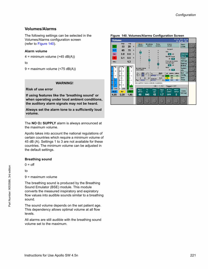
Configuration
Par
t Num
ber:
905
3586
, 3rd
edi
tion
Volumes/Alarms
Figure 140. Volumes/Alarms Configuration ScreenThe following settings can be selected in the Volumes/Alarms configuration screen(refer to Figure 140).
Alarm volume
4 = minimum volume (>45 dB(A))
to
9 = maximum volume (<75 dB(A))
The NO O2 SUPPLY alarm is always announced at the maximum volume.
Apollo takes into account the national regulations of certain countries which require a minimum volume of 45 dB (A). Settings 1 to 3 are not available for these countries. The minimum volume can be adjusted in the default settings.
Breathing sound
0 = off
to
9 = maximum volume
The breathing sound is produced by the Breathing Sound Emulator (BSE) module. This module converts the measured inspiratory and expiratory flow values into audible sounds similar to a breathing sound.
The sound volume depends on the set patient age. This dependency allows optimal volume at all flow levels.
All alarms are still audible with the breathing sound volume set to the maximum.
WARNING!
Risk of use error
If using features like the ’breathing sound’ or when operating under loud ambient conditions, the auditory alarm signals may not be heard.
Always set the alarm tone to a sufficiently loud volume.
Instructions for Use Apollo SW 4.5n 221
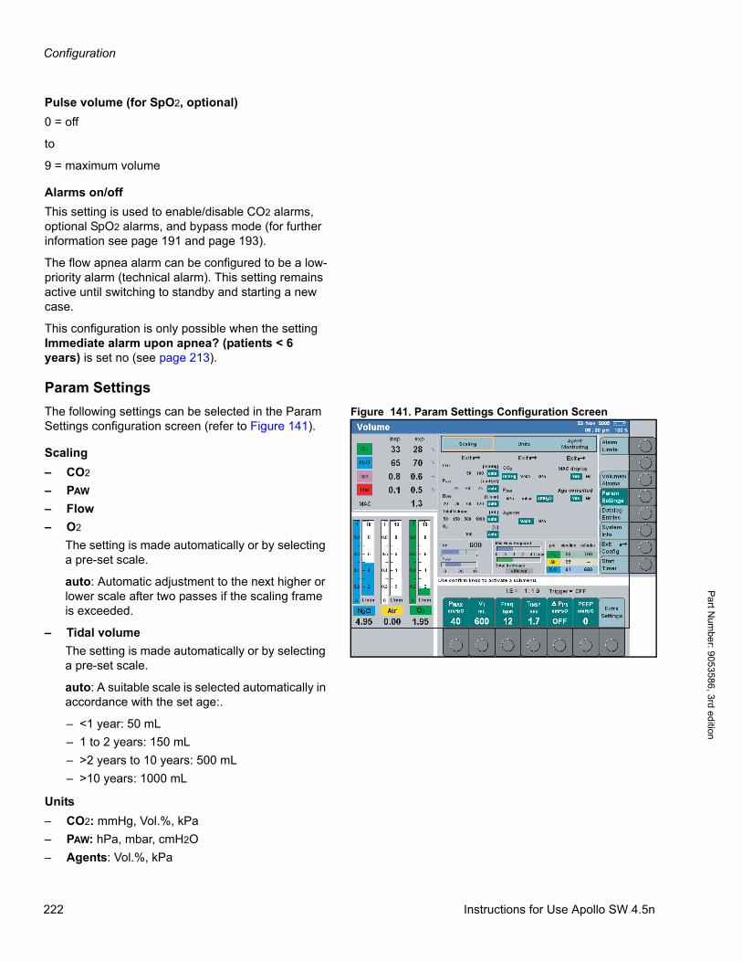
Configuration
Pa
rt Num
ber: 905358
6, 3rd edition
Pulse volume (for SpO2, optional)
0 = off
to
9 = maximum volume
Alarms on/off
This setting is used to enable/disable CO2 alarms, optional SpO2 alarms, and bypass mode (for further information see page 191 and page 193).
The flow apnea alarm can be configured to be a low-priority alarm (technical alarm). This setting remains active until switching to standby and starting a new case.
This configuration is only possible when the setting Immediate alarm upon apnea? (patients < 6 years) is set no (see page 213).
Param Settings
Figure 141. Param Settings Configuration ScreenThe following settings can be selected in the Param Settings configuration screen (refer to Figure 141).
Scaling
– CO2
– PAW
– Flow
– O2
The setting is made automatically or by selecting a pre-set scale.
auto: Automatic adjustment to the next higher or lower scale after two passes if the scaling frame is exceeded.
– Tidal volume
The setting is made automatically or by selecting a pre-set scale.
auto: A suitable scale is selected automatically in accordance with the set age:.
– <1 year: 50 mL
– 1 to 2 years: 150 mL
– >2 years to 10 years: 500 mL
– >10 years: 1000 mL
Units
– CO2: mmHg, Vol.%, kPa
– PAW: hPa, mbar, cmH2O
– Agents: Vol.%, kPa
222 Instructions for Use Apollo SW 4.5n
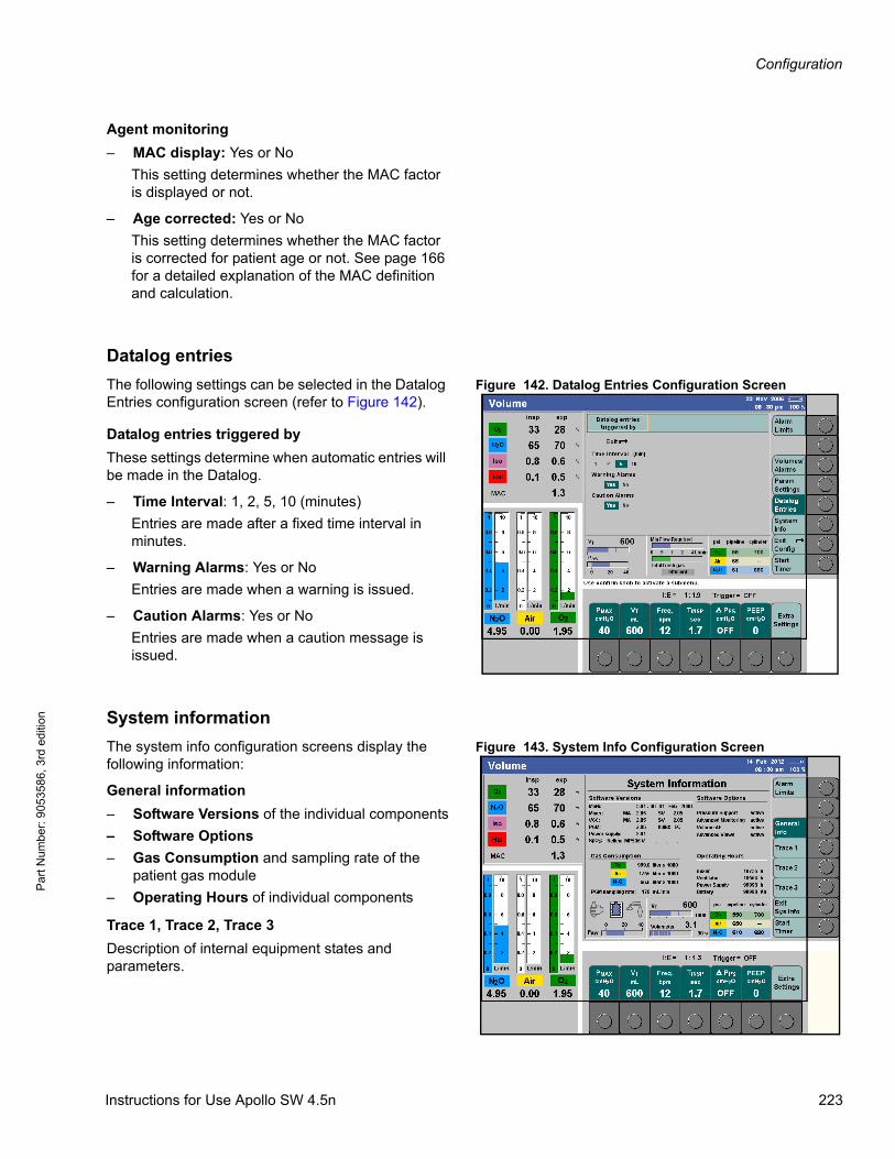
Configuration
Par
t Num
ber:
905
3586
, 3rd
edi
tion
Agent monitoring
– MAC display: Yes or No
This setting determines whether the MAC factor is displayed or not.
– Age corrected: Yes or No
This setting determines whether the MAC factor is corrected for patient age or not. See page 166 for a detailed explanation of the MAC definition and calculation.
Datalog entries
Figure 142. Datalog Entries Configuration ScreenThe following settings can be selected in the Datalog Entries configuration screen (refer to Figure 142).
Datalog entries triggered by
These settings determine when automatic entries will be made in the Datalog.
– Time Interval: 1, 2, 5, 10 (minutes)
Entries are made after a fixed time interval in minutes.
– Warning Alarms: Yes or No
Entries are made when a warning is issued.
– Caution Alarms: Yes or No
Entries are made when a caution message is issued.
System information
Figure 143. System Info Configuration ScreenThe system info configuration screens display the following information:
General information
– Software Versions of the individual components
– Software Options
– Gas Consumption and sampling rate of the patient gas module
– Operating Hours of individual components
Trace 1, Trace 2, Trace 3
Description of internal equipment states and parameters.
Instructions for Use Apollo SW 4.5n 223
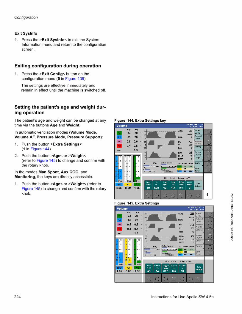
Configuration
Pa
rt Num
ber: 905358
6, 3rd edition
Exit SysInfo
1. Press the >Exit SysInfo< to exit the System Information menu and return to the configuration screen.
Exiting configuration during operation
1. Press the >Exit Config< button on the configuration menu (5 in Figure 139).
The settings are effective immediately and remain in effect until the machine is switched off.
Setting the patient’s age and weight dur-ing operation
Figure 144. Extra Settings keyThe patient’s age and weight can be changed at any time via the buttons Age and Weight.
In automatic ventilation modes (Volume Mode, Volume AF, Pressure Mode, Pressure Support):
1. Push the button >Extra Settings<(1 in Figure 144).
2. Push the button >Age< or >Weight<(refer to Figure 145) to change and confirm with the rotary knob.
In the modes Man.Spont, Aux CGO, and Monitoring, the keys are directly accessible.
1. Push the button >Age< or >Weight< (refer to Figure 145) to change and confirm with the rotary knob.
Figure 145. Extra Settings
1
224 Instructions for Use Apollo SW 4.5n

Cleaning and Maintenance
Par
t Num
ber:
905
3586
, 3rd
edi
tion
Cleaning and Maintenance
ContentsOverview . . . . . . . . . . . . . . . . . . . . . . . . . . . . . . . . . . . . . . . . . . . . . . . . . . . . . . . . . . . . . . . . . . . . . . . . . . . . . . 227
Disassembling components . . . . . . . . . . . . . . . . . . . . . . . . . . . . . . . . . . . . . . . . . . . . . . . . . . . . . . . . . . . . . . 227
Observe before disassembly . . . . . . . . . . . . . . . . . . . . . . . . . . . . . . . . . . . . . . . . . . . . . . . . . . . . . . . . . . . . . . . 227
Removing the sample line . . . . . . . . . . . . . . . . . . . . . . . . . . . . . . . . . . . . . . . . . . . . . . . . . . . . . . . . . . . . . . . . . 227
Removing the water trap . . . . . . . . . . . . . . . . . . . . . . . . . . . . . . . . . . . . . . . . . . . . . . . . . . . . . . . . . . . . . . . . . . 228
Removing the patient system hoses . . . . . . . . . . . . . . . . . . . . . . . . . . . . . . . . . . . . . . . . . . . . . . . . . . . . . . . . . . 228
Removing the absorber . . . . . . . . . . . . . . . . . . . . . . . . . . . . . . . . . . . . . . . . . . . . . . . . . . . . . . . . . . . . . . . . . . . 230
Reusable absorber . . . . . . . . . . . . . . . . . . . . . . . . . . . . . . . . . . . . . . . . . . . . . . . . . . . . . . . . . . . . . . . . . . . . 230
Disposable CLIC absorber (optional) . . . . . . . . . . . . . . . . . . . . . . . . . . . . . . . . . . . . . . . . . . . . . . . . . . . . . . 230
Removing the breathing system . . . . . . . . . . . . . . . . . . . . . . . . . . . . . . . . . . . . . . . . . . . . . . . . . . . . . . . . . . . . . 230
Removing the ventilator diaphragm . . . . . . . . . . . . . . . . . . . . . . . . . . . . . . . . . . . . . . . . . . . . . . . . . . . . . . . . . . 231
Removing the flow sensors . . . . . . . . . . . . . . . . . . . . . . . . . . . . . . . . . . . . . . . . . . . . . . . . . . . . . . . . . . . . . . . . 231
Opening the breathing system . . . . . . . . . . . . . . . . . . . . . . . . . . . . . . . . . . . . . . . . . . . . . . . . . . . . . . . . . . . . . . 232
Removing the anesthetic gas receiving system AGS (optional) . . . . . . . . . . . . . . . . . . . . . . . . . . . . . . . . . . . . . 233
Removing the passive scavenger system (optional) . . . . . . . . . . . . . . . . . . . . . . . . . . . . . . . . . . . . . . . . . . . . . 234
Removing the endotracheal aspiration system (optional) . . . . . . . . . . . . . . . . . . . . . . . . . . . . . . . . . . . . . . . . . . 234
Cleaning and Disinfection Guidelines . . . . . . . . . . . . . . . . . . . . . . . . . . . . . . . . . . . . . . . . . . . . . . . . . . . . . . 235
Proper Cleaning/Disinfection Sequence . . . . . . . . . . . . . . . . . . . . . . . . . . . . . . . . . . . . . . . . . . . . . . . . . . . . 235
Cleaning/Disinfection Objective and Methods . . . . . . . . . . . . . . . . . . . . . . . . . . . . . . . . . . . . . . . . . . . . . . . 236
Disinfecting/Cleaning/Sterilizing . . . . . . . . . . . . . . . . . . . . . . . . . . . . . . . . . . . . . . . . . . . . . . . . . . . . . . . . . . . 237
Choice of disinfectant . . . . . . . . . . . . . . . . . . . . . . . . . . . . . . . . . . . . . . . . . . . . . . . . . . . . . . . . . . . . . . . . . . . . . 237
Surfaces . . . . . . . . . . . . . . . . . . . . . . . . . . . . . . . . . . . . . . . . . . . . . . . . . . . . . . . . . . . . . . . . . . . . . . . . . . . . . . . 237
Breathing system and absorber . . . . . . . . . . . . . . . . . . . . . . . . . . . . . . . . . . . . . . . . . . . . . . . . . . . . . . . . . . . . . 238
Care list for Apollo components . . . . . . . . . . . . . . . . . . . . . . . . . . . . . . . . . . . . . . . . . . . . . . . . . . . . . . . . . . . 239
Reassembling components . . . . . . . . . . . . . . . . . . . . . . . . . . . . . . . . . . . . . . . . . . . . . . . . . . . . . . . . . . . . . . . 240
Visual inspection . . . . . . . . . . . . . . . . . . . . . . . . . . . . . . . . . . . . . . . . . . . . . . . . . . . . . . . . . . . . . . . . . . . . . . . . . 240
Assembling the breathing system . . . . . . . . . . . . . . . . . . . . . . . . . . . . . . . . . . . . . . . . . . . . . . . . . . . . . . . . . . . . 241
Inserting the flow sensors . . . . . . . . . . . . . . . . . . . . . . . . . . . . . . . . . . . . . . . . . . . . . . . . . . . . . . . . . . . . . . . . . . 241
Installing the ventilator diaphragm . . . . . . . . . . . . . . . . . . . . . . . . . . . . . . . . . . . . . . . . . . . . . . . . . . . . . . . . . . . 242
Installing the breathing system . . . . . . . . . . . . . . . . . . . . . . . . . . . . . . . . . . . . . . . . . . . . . . . . . . . . . . . . . . . . . . 242
Filling and installing the absorber . . . . . . . . . . . . . . . . . . . . . . . . . . . . . . . . . . . . . . . . . . . . . . . . . . . . . . . . . . . . 243
Reusable absorber . . . . . . . . . . . . . . . . . . . . . . . . . . . . . . . . . . . . . . . . . . . . . . . . . . . . . . . . . . . . . . . . . . . . 230
Disposable CLIC absorber (optional) . . . . . . . . . . . . . . . . . . . . . . . . . . . . . . . . . . . . . . . . . . . . . . . . . . . . . . 230
Installing the breathing bag and arm . . . . . . . . . . . . . . . . . . . . . . . . . . . . . . . . . . . . . . . . . . . . . . . . . . . . . . . . . 245
Connecting the breathing hoses . . . . . . . . . . . . . . . . . . . . . . . . . . . . . . . . . . . . . . . . . . . . . . . . . . . . . . . . . . . . . 246
Installing the water trap and sample line . . . . . . . . . . . . . . . . . . . . . . . . . . . . . . . . . . . . . . . . . . . . . . . . . . . . . . 246
Reassembling the anesthetic gas receiving system AGS (Optional) . . . . . . . . . . . . . . . . . . . . . . . . . . . . . . . . . 247
Instructions for Use Apollo SW 4.5n 225
Cleaning and Maintenance
Pa
rt Num
ber: 905358
6, 3rd edition
Connecting the anesthetic gas receiving system AGS (Optional) . . . . . . . . . . . . . . . . . . . . . . . . . . . . . . . . . . . . 248
Connecting the passive scavenger system (Optional) . . . . . . . . . . . . . . . . . . . . . . . . . . . . . . . . . . . . . . . . . . . . 249
Connecting the endotracheal aspiration system (Optional) . . . . . . . . . . . . . . . . . . . . . . . . . . . . . . . . . . . . . . . . 250
Maintenance . . . . . . . . . . . . . . . . . . . . . . . . . . . . . . . . . . . . . . . . . . . . . . . . . . . . . . . . . . . . . . . . . . . . . . . . . . . 251
Overview . . . . . . . . . . . . . . . . . . . . . . . . . . . . . . . . . . . . . . . . . . . . . . . . . . . . . . . . . . . . . . . . . . . . . . . . . . . . . . . 251
Definition ot maintenance concepts . . . . . . . . . . . . . . . . . . . . . . . . . . . . . . . . . . . . . . . . . . . . . . . . . . . . . . . . . . 251
Inspection . . . . . . . . . . . . . . . . . . . . . . . . . . . . . . . . . . . . . . . . . . . . . . . . . . . . . . . . . . . . . . . . . . . . . . . . . . . . . . 252
Emptying or replacing the water trap . . . . . . . . . . . . . . . . . . . . . . . . . . . . . . . . . . . . . . . . . . . . . . . . . . . . . . . . . 254
Emptying the water trap . . . . . . . . . . . . . . . . . . . . . . . . . . . . . . . . . . . . . . . . . . . . . . . . . . . . . . . . . . . . . . . . 254
Replacing the water trap . . . . . . . . . . . . . . . . . . . . . . . . . . . . . . . . . . . . . . . . . . . . . . . . . . . . . . . . . . . . . . . . 255
Disposing of the medical device . . . . . . . . . . . . . . . . . . . . . . . . . . . . . . . . . . . . . . . . . . . . . . . . . . . . . . . . . . . 255
226 Instructions for Use Apollo SW 4.5n
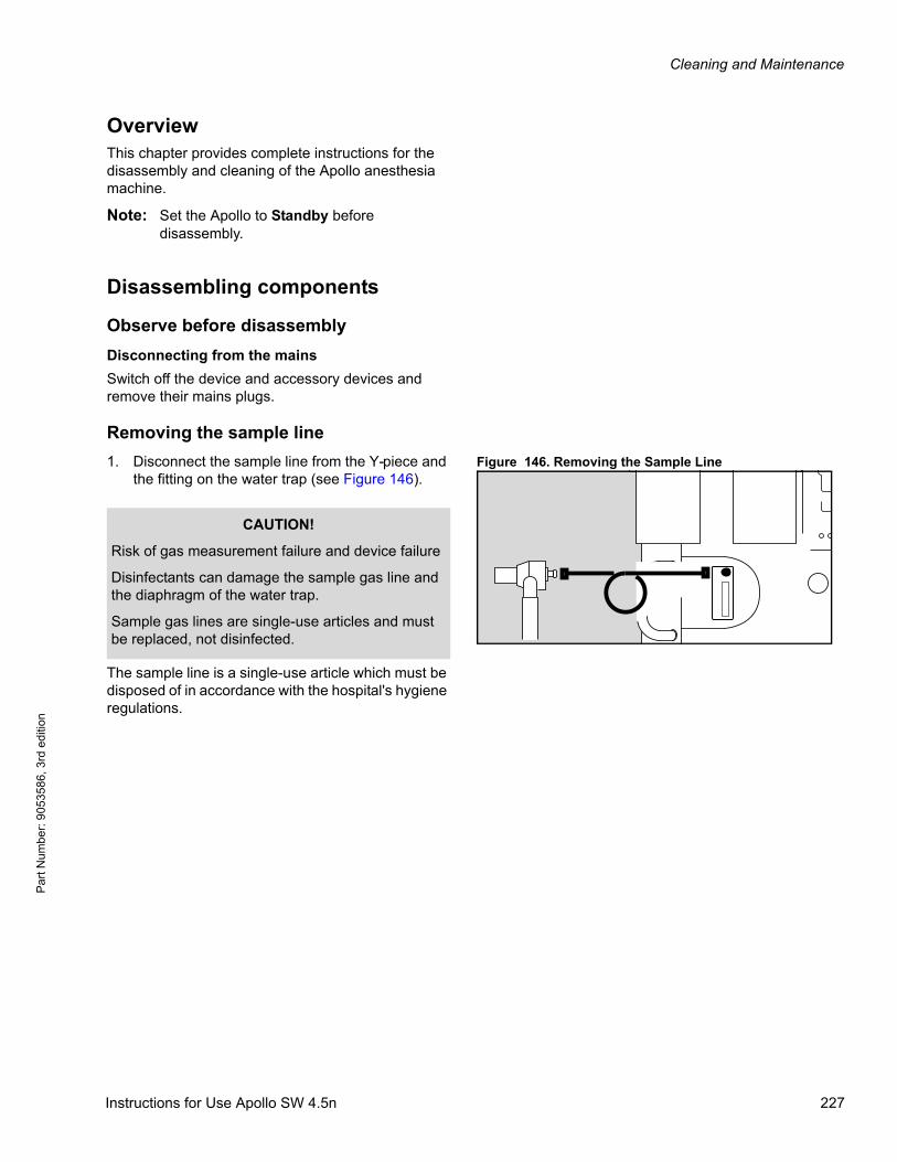
Cleaning and Maintenance
Par
t Num
ber:
905
3586
, 3rd
edi
tion
OverviewThis chapter provides complete instructions for the disassembly and cleaning of the Apollo anesthesia machine.
Note: Set the Apollo to Standby before disassembly.
Disassembling components
Observe before disassembly
Disconnecting from the mains
Switch off the device and accessory devices and remove their mains plugs.
Removing the sample line
Figure 146. Removing the Sample Line1. Disconnect the sample line from the Y-piece and the fitting on the water trap (see Figure 146).
The sample line is a single-use article which must be disposed of in accordance with the hospital's hygiene regulations.
CAUTION!
Risk of gas measurement failure and device failure
Disinfectants can damage the sample gas line and the diaphragm of the water trap.
Sample gas lines are single-use articles and must be replaced, not disinfected.
Instructions for Use Apollo SW 4.5n 227

Cleaning and Maintenance
Pa
rt Num
ber: 905358
6, 3rd edition
Removing the water trap
Figure 147. Removing the Water Trap1. Pull the water trap straight out of its holder.
For disposal of the old water trap follow the corresponding Instructions for Use of the water trap WaterLock and comply with the hospital’s hygiene requirements.
Removing the patient system hoses
Figure 148. Patient System Hoses1. Disconnect the breathing hoses from the breathing system (1 in Figure 148).
2. Disconnect the various parts of the hose system (breathing hoses, Y-piece, connector, and optional Y-piece filter). The filter on the Y-piece is not reusable and can be disposed of with ordinary domestic waste.
Note the regulations of the hospital for infectious patients!
Note the Instructions for Use.
3. Disconnect the breathing bag and arm(2 in Figure 148) by loosening the two thumb screws.
4. Prepare the parts for conditioning in a cleaning and disinfection machine.
WARNING!
Risk of measurement failure and device failure
If the water trap is used longer than intended, the diaphragm may become brittle and allow water and bacteria to enter the measurement system. Such contamination affects the gas measurement which may fail as a result.
The water trap must be replaced at least every four weeks.
12
228 Instructions for Use Apollo SW 4.5n
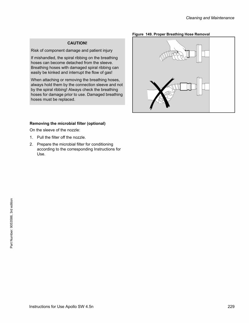
Cleaning and Maintenance
Par
t Num
ber:
905
3586
, 3rd
edi
tion
Figure 149. Proper Breathing Hose Removal
Removing the microbial filter (optional)
On the sleeve of the nozzle:
1. Pull the filter off the nozzle.
2. Prepare the microbial filter for conditioning according to the corresponding Instructions for Use.
CAUTION!
Risk of component damage and patient injury
If mishandled, the spiral ribbing on the breathing hoses can become detached from the sleeve. Breathing hoses with damaged spiral ribbing can easily be kinked and interrupt the flow of gas!
When attaching or removing the breathing hoses, always hold them by the connection sleeve and not by the spiral ribbing! Always check the breathing hoses for damage prior to use. Damaged breathing hoses must be replaced.
Instructions for Use Apollo SW 4.5n 229
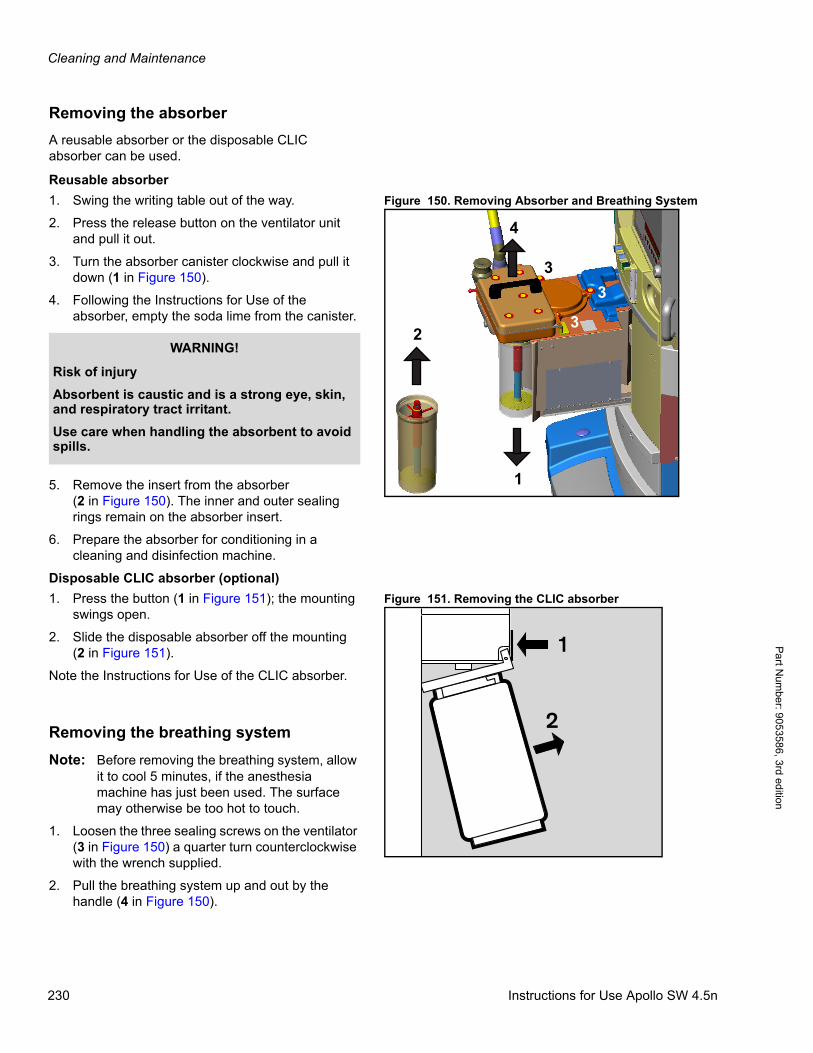
Cleaning and Maintenance
Pa
rt Num
ber: 905358
6, 3rd edition
Removing the absorber
A reusable absorber or the disposable CLIC absorber can be used.
Reusable absorber
Figure 150. Removing Absorber and Breathing System1. Swing the writing table out of the way.
2. Press the release button on the ventilator unit and pull it out.
3. Turn the absorber canister clockwise and pull it down (1 in Figure 150).
4. Following the Instructions for Use of the absorber, empty the soda lime from the canister.
5. Remove the insert from the absorber(2 in Figure 150). The inner and outer sealing rings remain on the absorber insert.
6. Prepare the absorber for conditioning in a cleaning and disinfection machine.
Disposable CLIC absorber (optional)
Figure 151. Removing the CLIC absorber1. Press the button (1 in Figure 151); the mounting swings open.
2. Slide the disposable absorber off the mounting(2 in Figure 151).
Note the Instructions for Use of the CLIC absorber.
Removing the breathing system
Note: Before removing the breathing system, allow it to cool 5 minutes, if the anesthesia machine has just been used. The surface may otherwise be too hot to touch.
1. Loosen the three sealing screws on the ventilator (3 in Figure 150) a quarter turn counterclockwise with the wrench supplied.
2. Pull the breathing system up and out by the handle (4 in Figure 150).
3
2
1
3
3
4
WARNING!
Risk of injury
Absorbent is caustic and is a strong eye, skin, and respiratory tract irritant.
Use care when handling the absorbent to avoid spills.
33
1
2
230 Instructions for Use Apollo SW 4.5n
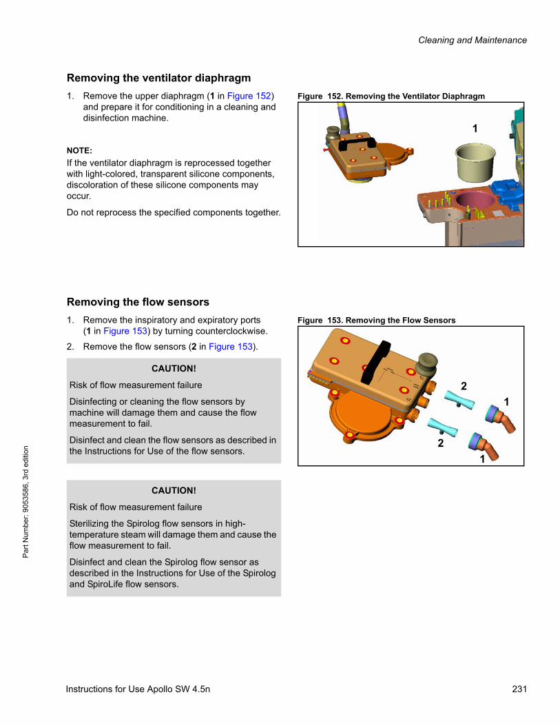
Cleaning and Maintenance
Par
t Num
ber:
905
3586
, 3rd
edi
tion
Removing the ventilator diaphragm
Figure 152. Removing the Ventilator Diaphragm1. Remove the upper diaphragm (1 in Figure 152) and prepare it for conditioning in a cleaning and disinfection machine.
Removing the flow sensors
Figure 153. Removing the Flow Sensors1. Remove the inspiratory and expiratory ports(1 in Figure 153) by turning counterclockwise.
2. Remove the flow sensors (2 in Figure 153).
1
NOTE:
If the ventilator diaphragm is reprocessed together with light-colored, transparent silicone components, discoloration of these silicone components may occur.
Do not reprocess the specified components together.
2
2
1
1
CAUTION!
Risk of flow measurement failure
Disinfecting or cleaning the flow sensors by machine will damage them and cause the flow measurement to fail.
Disinfect and clean the flow sensors as described in the Instructions for Use of the flow sensors.
CAUTION!
Risk of flow measurement failure
Sterilizing the Spirolog flow sensors in high-temperature steam will damage them and cause the flow measurement to fail.
Disinfect and clean the Spirolog flow sensor as described in the Instructions for Use of the Spirolog and SpiroLife flow sensors.
Instructions for Use Apollo SW 4.5n 231

Cleaning and Maintenance
Pa
rt Num
ber: 905358
6, 3rd edition
Opening the breathing system
Figure 154. Opening the Breathing System1. Loosen the five sealing screws (1 in Figure 154) a quarter turn counterclockwise with the key(2 in Figure 154) supplied.
2. Remove the cover.
Figure 155. Removing the Valve Plate3. Lift off the metal valve plate (1 in Figure 155).
4. Prepare the housing parts for conditioning in a cleaning and disinfection machine.
5. Place the metal valve plate in the cleaning and disinfection machine.
1
1
11
1
2
1
232 Instructions for Use Apollo SW 4.5n
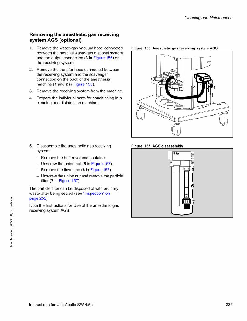
Cleaning and Maintenance
Par
t Num
ber:
905
3586
, 3rd
edi
tion
Removing the anesthetic gas receiving system AGS (optional)
Figure 156. Anesthetic gas receiving system AGS1. Remove the waste-gas vacuum hose connected between the hospital waste-gas disposal system and the output connection (3 in Figure 156) on the receiving system.
2. Remove the transfer hose connected between the receiving system and the scavenger connection on the back of the anesthesia machine (1 and 2 in Figure 156).
3. Remove the receiving system from the machine.
4. Prepare the individual parts for conditioning in a cleaning and disinfection machine.
Figure 157. AGS disassembly5. Disassemble the anesthetic gas receiving system:
– Remove the buffer volume container.
– Unscrew the union nut (5 in Figure 157).
– Remove the flow tube (6 in Figure 157).
– Unscrew the union nut and remove the particle filter (7 in Figure 157).
The particle filter can be disposed of with ordinary waste after being sealed (see “Inspection” on page 252).
Note the Instructions for Use of the anesthetic gas receiving system AGS.
13
4
2
6
D
5
7
Instructions for Use Apollo SW 4.5n 233

Cleaning and Maintenance
Pa
rt Num
ber: 905358
6, 3rd edition
Removing the passive scavenger system (optional)
Figure 158. Passive Scavenger System1. Remove the waste-gas hose connected between the hospital waste-gas disposal system and the bottom connection on the scavenger(1 in Figure 158).
2. Remove the scavenger hose connected between the scavenger and the scavenger connection on the back of the anesthesia machine(2 in Figure 158).
3. Remove the scavenger system from the machine.
4. Prepare the parts for conditioning in a cleaning and disinfection machine.
Note: For cleaning/disinfection instructions for the passive scavenger system, refer to its Instructions for Use.
Removing the endotracheal aspiration system (optional)
Figure 159. Endotracheal aspiration system bracket and regulator
1. Remove the suction bottle from the slide mount (1 in Figure 159).
2. Remove the suction regulator from the bracket(2 in Figure 159).
3. Remove the endotracheal aspiration system bracket from the side rail on the side of the anesthesia machine.
4. If using a disposable suction bottle, dispose of the bottle with infectious waste.
5. If using a reusable suction bottle, empty the bottle and dispose of contents with infectious waste.
1
2
21
WARNING!
Risk of infection
Fluids gathered in the suction bottle may be infectious and therefore dangerous for hospital personnel.
Always wear gloves when emptying the suction bottle.
234 Instructions for Use Apollo SW 4.5n
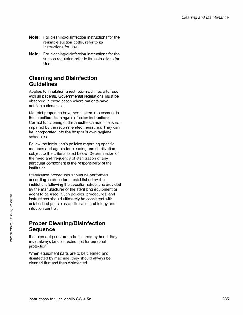
Cleaning and Maintenance
Par
t Num
ber:
905
3586
, 3rd
edi
tion
Note: For cleaning/disinfection instructions for the reusable suction bottle, refer to its Instructions for Use.
Note: For cleaning/disinfection instructions for the suction regulator, refer to its Instructions for Use.
Cleaning and Disinfection GuidelinesApplies to inhalation anesthetic machines after use with all patients. Governmental regulations must be observed in those cases where patients have notifiable diseases.
Material properties have been taken into account in the specified cleaning/disinfection instructions. Correct functioning of the anesthesia machine is not impaired by the recommended measures. They can be incorporated into the hospital's own hygiene schedules.
Follow the institution’s policies regarding specific methods and agents for cleaning and sterilization, subject to the criteria listed below. Determination of the need and frequency of sterilization of any particular component is the responsibility of the institution.
Sterilization procedures should be performed according to procedures established by the institution, following the specific instructions provided by the manufacturer of the sterilizing equipment or agent to be used. Such policies, procedures, and instructions should ultimately be consistent with established principles of clinical microbiology and infection control.
Proper Cleaning/Disinfection SequenceIf equipment parts are to be cleaned by hand, they must always be disinfected first for personal protection.
When equipment parts are to be cleaned and disinfected by machine, they should always be cleaned first and then disinfected.
Instructions for Use Apollo SW 4.5n 235

Cleaning and Maintenance
Pa
rt Num
ber: 905358
6, 3rd edition
Cleaning/Disinfection Objective and MethodsThe purpose of the described cleaning/disinfection measures is to provide each patient with a reliably disinfected anesthetic machine, i.e. a machine free from all unhealthy micro-organisms. Sterility is required only for the intubation tube and bronchial aspiration catheter.
The following disinfection methods may be used:
– Disinfection by wiping the surface of the device (see “Choice of disinfectant” on page 237)
– Mechanical cleaning with high-temperature disinfection (≥199 °F (93 °C) , ≥10 min). This is the preferred method for many Apollo components; a suitable cleaning agent must be added.
– Manual disinfection in a bath. Extensive personal protection is required due to inhalation of vapors.
Equipment parts should be cleaned and disinfected by machine for hygienic conditioning purposes(EN ISO 15883, in preparation).
Complex, thermally stable functional components, such as the breathing system, can be easily cleaned and disinfected by machine, but are not always dried sufficiently. Subsequent vacuum disinfection in hot steam or steam sterilization is recommended to dry off the remaining water.
– Vacuum disinfection in hot steam at 167 °F (75 °C) for 20 minutes or 221 °F (105 °C) for 1 minute, for example.
– Steam sterilization, for example at 250 °F (121 °C) for max. 20 minutes or 273 °F (134 °C) for max. 8 minutes. Higher temperatures may impair the service life of the functional components.
High-temperature disinfection does not have any cleaning effect. Such methods should therefore only be used on functional components which have already been cleaned by hand or by machine.
Machines, associated components, and equipment parts must be inspected visually and packaged for storage or transport. Simple packaging with corresponding labeling is sufficient for this purpose. This is not necessary if the components and equipment parts are not to be stored and/or transported.
236 Instructions for Use Apollo SW 4.5n
Cleaning and Maintenance
Par
t Num
ber:
905
3586
, 3rd
edi
tion
Disinfecting/Cleaning/Sterilizing
Choice of disinfectant
Only products suitable for surface disinfection may be used for disinfection. Testing was performed with Incidin Extra N and Incidur (wiping), and Gigasept FF and Korsolex Extra (disinfection by immersion).
The following products are not suitable and should not be used:
– Compounds containing phenols
– Halogen-releasing compounds
– Strong organic acids
– Oxygen-releasing compounds
In addition to the main agents, disinfectants frequently also contain additives which may damage the materials used. The supplier/manufacturer of the cleaning agent/disinfectant should be contacted if there is any doubt as to the suitability of a product.
Surfaces
Surfaces of the Apollo, compressed gas hoses, and cables:
– Wipe off impurities with a damp disposable cloth.
– Disinfect with a wipe disinfectant. (Note the manufacturer's Instructions for Use.)
WARNING!
Risk of electric shock
Fluids entering the device can damage it causing malfunctions and endangering the patient. Wipe the device with only moist, not dripping wet, objects, e.g. sponges or rags. Do not place canisters with liquids on or over the device.
Do not allow any liquids to enter openings in the device.
Instructions for Use Apollo SW 4.5n 237
Cleaning and Maintenance
Pa
rt Num
ber: 905358
6, 3rd edition
Breathing system and absorber
– All parts of the breathing system, including ventilator diaphragm, Y-piece, breathing hoses, breathing bag (but not including the Spirolog or SpiroLife flow sensors)
– Parts of the absorber
These parts can be thermally disinfected in an automatic cleaning and disinfection machine at 199 °F (93 °C) for 10 minutes.Only neutral cleaning agents and fully demineralized water may be used. Chemical disinfectants need not to be added for thermal disinfection; they may cause corrosion.
Wipe the heating contacts of the metal valve plate and their counterparts on the ventilator module with a cloth to remove detergent residue.
CAUTION!
Risk of failure of flow measurement
Improper reprocessing and soiling, such as deposits or particles, can damage the flow sensor.
– No machine cleaning or disinfection
– No plasma sterilization or radiation sterilization
– No water jets, compressed air, brushes or the like
– No ultrasonic bath
– No hot-steam sterilization with Spirolog and Infinity ID flow sensors
– Clean and disinfect the flow sensor in accordance with the corresponding instructions for use.
– For disinfecting the flow sensor use only clean disinfectant solutions.
WARNING!
Risk of device failure and patient injury
Correct operation of the anesthesia machine may be impaired and lead to failure of the anesthesia machine if the control areas in the valve plate are not dried completely.
The valve plate must be sterilized after washing in order to dry it.
238 Instructions for Use Apollo SW 4.5n
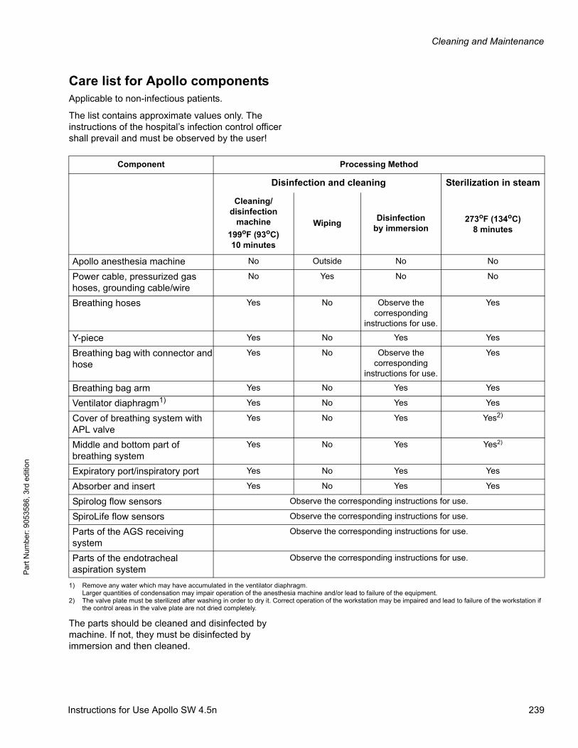
Cleaning and Maintenance
Par
t Num
ber:
905
3586
, 3rd
edi
tion
Care list for Apollo componentsApplicable to non-infectious patients.
The list contains approximate values only. The instructions of the hospital’s infection control officer shall prevail and must be observed by the user!
The parts should be cleaned and disinfected by machine. If not, they must be disinfected by immersion and then cleaned.
Component Processing Method
Disinfection and cleaning Sterilization in steam
Cleaning/disinfection
machine
199oF (93oC)10 minutes
WipingDisinfection
by immersion273oF (134oC)
8 minutes
Apollo anesthesia machine No Outside No No
Power cable, pressurized gas hoses, grounding cable/wire
No Yes No No
Breathing hoses Yes No Observe the corresponding
instructions for use.
Yes
Y-piece Yes No Yes Yes
Breathing bag with connector and hose
Yes No Observe the corresponding
instructions for use.
Yes
Breathing bag arm Yes No Yes Yes
Ventilator diaphragm1) Yes No Yes Yes
Cover of breathing system with APL valve
Yes No Yes Yes2)
Middle and bottom part of breathing system
Yes No Yes Yes2)
Expiratory port/inspiratory port Yes No Yes Yes
Absorber and insert Yes No Yes Yes
Spirolog flow sensors Observe the corresponding instructions for use.
SpiroLife flow sensors Observe the corresponding instructions for use.
Parts of the AGS receiving system
Observe the corresponding instructions for use.
Parts of the endotracheal aspiration system
Observe the corresponding instructions for use.
1) Remove any water which may have accumulated in the ventilator diaphragm.Larger quantities of condensation may impair operation of the anesthesia machine and/or lead to failure of the equipment.
2) The valve plate must be sterilized after washing in order to dry it. Correct operation of the workstation may be impaired and lead to failure of the workstation if the control areas in the valve plate are not dried completely.
Instructions for Use Apollo SW 4.5n 239
Cleaning and Maintenance
Pa
rt Num
ber: 905358
6, 3rd edition
Reassembling components
Visual inspection
1. Inspect all parts for damage and wear, e.g. cracking, embrittlement or major hardening and residual soiling.
2. If necessary, use a dry cloth to remove residual cleaning agent and disinfectants from the valve plate, the ventilator module, and the pins of the breathing system heating.
CAUTION!
Risk of device failure
If inappropriate substances are used for hygienic preparation, the device and its components may be damaged (corrosion, condensation).
Apollo and its components must not be treated with formaldehyde vapors or ethylene oxide.
WARNING!
Risk of scavenger becoming blocked
If objects such as packing foil get into the device, e.g., the breathing system or the ventilator drawer, the scavenger may become blocked.
Make sure that there is no packing material left inside the device.
CAUTION!
Risk of faulty components
Even accessories designed to be reused and removable device parts have a limited service life. Handling and reprocessing can increase wear and markedly shorten service life (e.g., disinfectant residues can attack the material more intensely during autoclaving).
If signs of wear become visible, such as cracks, deformation, discoloration, peeling, etc., affected accessories must be replaced.
240 Instructions for Use Apollo SW 4.5n
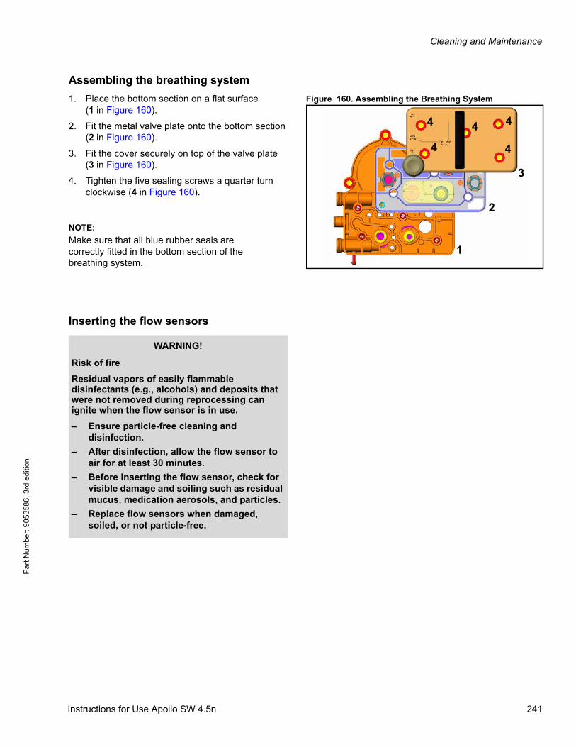
Cleaning and Maintenance
Par
t Num
ber:
905
3586
, 3rd
edi
tion
Assembling the breathing system
Figure 160. Assembling the Breathing System1. Place the bottom section on a flat surface(1 in Figure 160).
2. Fit the metal valve plate onto the bottom section (2 in Figure 160).
3. Fit the cover securely on top of the valve plate(3 in Figure 160).
4. Tighten the five sealing screws a quarter turn clockwise (4 in Figure 160).
Inserting the flow sensors
1
2
3
4
4
4 4
4
NOTE:
Make sure that all blue rubber seals are correctly fitted in the bottom section of the breathing system.
WARNING!
Risk of fire
Residual vapors of easily flammable disinfectants (e.g., alcohols) and deposits that were not removed during reprocessing can ignite when the flow sensor is in use.
– Ensure particle-free cleaning and disinfection.
– After disinfection, allow the flow sensor to air for at least 30 minutes.
– Before inserting the flow sensor, check for visible damage and soiling such as residual mucus, medication aerosols, and particles.
– Replace flow sensors when damaged, soiled, or not particle-free.
Instructions for Use Apollo SW 4.5n 241
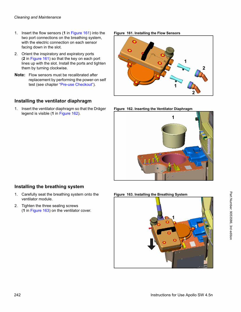
Cleaning and Maintenance
Pa
rt Num
ber: 905358
6, 3rd edition
Figure 161. Installing the Flow Sensors1. Insert the flow sensors (1 in Figure 161) into the two port connections on the breathing system, with the electric connection on each sensor facing down in the slot.
2. Orient the inspiratory and expiratory ports(2 in Figure 161) so that the key on each port lines up with the slot. Install the ports and tighten them by turning clockwise.
Note: Flow sensors must be recalibrated after replacement by performing the power-on self test (see chapter “Pre-use Checkout”).
Installing the ventilator diaphragm
Figure 162. Inserting the Ventilator Diaphragm1. Insert the ventilator diaphragm so that the Dräger legend is visible (1 in Figure 162).
Installing the breathing system
Figure 163. Installing the Breathing System1. Carefully seat the breathing system onto the ventilator module.
2. Tighten the three sealing screws(1 in Figure 163) on the ventilator cover.
1
1
2
2
1
1
1
1
242 Instructions for Use Apollo SW 4.5n
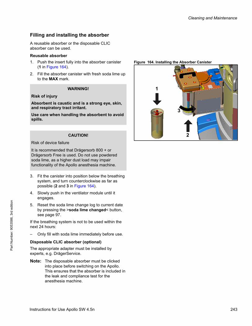
Cleaning and Maintenance
Par
t Num
ber:
905
3586
, 3rd
edi
tion
Filling and installing the absorber
A reusable absorber or the disposable CLIC absorber can be used.
Reusable absorber
Figure 164. Installing the Absorber Canister1. Push the insert fully into the absorber canister(1 in Figure 164).
2. Fill the absorber canister with fresh soda lime up to the MAX mark.
3. Fit the canister into position below the breathing system, and turn counterclockwise as far as possible (2 and 3 in Figure 164).
4. Slowly push in the ventilator module until it engages.
5. Reset the soda lime change log to current date by pressing the >soda lime changed< button, see page 97.
If the breathing system is not to be used within the next 24 hours:
– Only fill with soda lime immediately before use.
Disposable CLIC absorber (optional)
The appropriate adapter must be installed by experts, e.g. DrägerService.
Note: The disposable absorber must be clicked into place before switching on the Apollo. This ensures that the absorber is included in the leak and compliance test for the anesthesia machine.
1
2
3
WARNING!
Risk of injury
Absorbent is caustic and is a strong eye, skin, and respiratory tract irritant.
Use care when handling the absorbent to avoid spills.
CAUTION!
Risk of device failure
It is recommended that Drägersorb 800 + or Drägersorb Free is used. Do not use powdered soda lime, as a higher dust load may impair functionality of the Apollo anesthesia machine.
Instructions for Use Apollo SW 4.5n 243
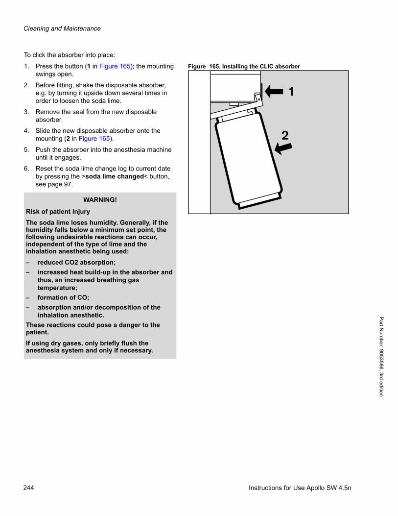
Cleaning and Maintenance
Pa
rt Num
ber: 905358
6, 3rd edition
To click the absorber into place:
Figure 165. Installing the CLIC absorber1. Press the button (1 in Figure 165); the mounting swings open.
2. Before fitting, shake the disposable absorber, e.g. by turning it upside down several times in order to loosen the soda lime.
3. Remove the seal from the new disposable absorber.
4. Slide the new disposable absorber onto the mounting (2 in Figure 165).
5. Push the absorber into the anesthesia machine until it engages.
6. Reset the soda lime change log to current date by pressing the >soda lime changed< button, see page 97.
1
2
WARNING!
Risk of patient injury
The soda lime loses humidity. Generally, if the humidity falls below a minimum set point, the following undesirable reactions can occur, independent of the type of lime and the inhalation anesthetic being used:
– reduced CO2 absorption;
– increased heat build-up in the absorber and thus, an increased breathing gas temperature;
– formation of CO;
– absorption and/or decomposition of the inhalation anesthetic.
These reactions could pose a danger to the patient.
If using dry gases, only briefly flush the anesthesia system and only if necessary.
244 Instructions for Use Apollo SW 4.5n
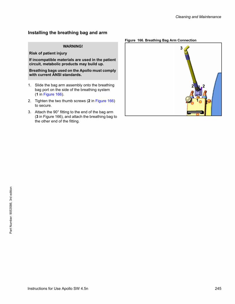
Cleaning and Maintenance
Par
t Num
ber:
905
3586
, 3rd
edi
tion
Installing the breathing bag and arm
Figure 166. Breathing Bag Arm Connection
1. Slide the bag arm assembly onto the breathing bag port on the side of the breathing system(1 in Figure 166).
2. Tighten the two thumb screws (2 in Figure 166) to secure.
3. Attach the 90° fitting to the end of the bag arm(3 in Figure 166), and attach the breathing bag to the other end of the fitting.
1
22
3WARNING!
Risk of patient injury
If incompatible materials are used in the patient circuit, metabolic products may build up.
Breathing bags used on the Apollo must comply with current ANSI standards.
Instructions for Use Apollo SW 4.5n 245

Cleaning and Maintenance
Pa
rt Num
ber: 905358
6, 3rd edition
Connecting the breathing hoses
Figure 167. Breathing Hose and Water Trap Connections
1. Connect each breathing hose (1 in Figure 167) to the inspiratory and expiratory port on the breathing system (2 in Figure 167).
2. Connect the other end of each breathing hose to the Y-piece (3 in Figure 167), or to the optional filter on the Y-piece.
Installing the water trap and sample line
1. Push the new or empty water trap into its holder on the front of the machine (4 in Figure 167) until it clicks into place.
2. Connect one end of the sample line to the Luer fitting on the water trap (5 in Figure 167).
3. Connect the other end of the sample line to the Luer fitting on the Y-piece (3 in Figure 167). Ensure that all Luer fittings are securely connected.
4. Make sure that the sample line is guided correctly by using the sample line clip. This clip
23
5
4
1
WARNING!
Risk of patient injury
If incompatible materials are used in the patient circuit, metabolic products may build up.
Breathing hoses used on the Apollo must comply with current ANSI standards.
WARNING!
Risk of burns
Conductive breathing hoses or face masks may cause burns during HF surgery.
Do not use these types of hoses and masks in combination with HF surgery.
WARNING!
Risk of patient injury
If the breathing hoses are incorrectly connected, the patient might be inadequately ventilated and supplied with fresh gas.
Make sure that all breathing hoses are correctly connected to the breathing system.
246 Instructions for Use Apollo SW 4.5n
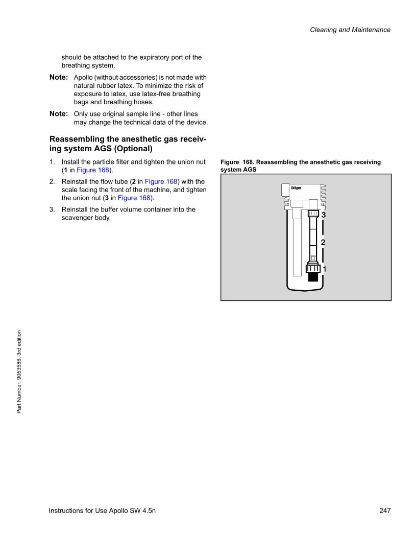
Cleaning and Maintenance
Par
t Num
ber:
905
3586
, 3rd
edi
tion
should be attached to the expiratory port of the breathing system.
Note: Apollo (without accessories) is not made with natural rubber latex. To minimize the risk of exposure to latex, use latex-free breathing bags and breathing hoses.
Note: Only use original sample line - other lines may change the technical data of the device.
Reassembling the anesthetic gas receiv-ing system AGS (Optional)
Figure 168. Reassembling the anesthetic gas receiving system AGS
1. Install the particle filter and tighten the union nut (1 in Figure 168).
2. Reinstall the flow tube (2 in Figure 168) with the scale facing the front of the machine, and tighten the union nut (3 in Figure 168).
3. Reinstall the buffer volume container into the scavenger body.
2
D
3
1
Instructions for Use Apollo SW 4.5n 247
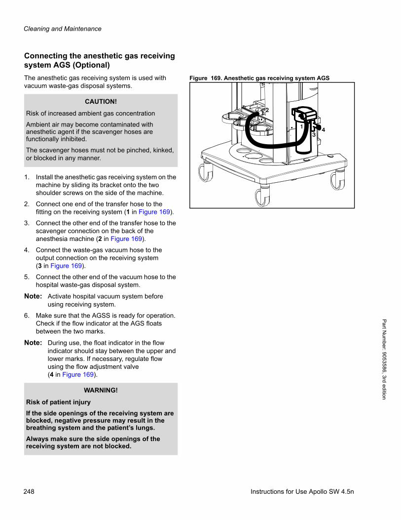
Cleaning and Maintenance
Pa
rt Num
ber: 905358
6, 3rd edition
Connecting the anesthetic gas receiving system AGS (Optional)
Figure 169. Anesthetic gas receiving system AGSThe anesthetic gas receiving system is used with vacuum waste-gas disposal systems.
1. Install the anesthetic gas receiving system on the machine by sliding its bracket onto the two shoulder screws on the side of the machine.
2. Connect one end of the transfer hose to the fitting on the receiving system (1 in Figure 169).
3. Connect the other end of the transfer hose to the scavenger connection on the back of the anesthesia machine (2 in Figure 169).
4. Connect the waste-gas vacuum hose to the output connection on the receiving system(3 in Figure 169).
5. Connect the other end of the vacuum hose to the hospital waste-gas disposal system.
Note: Activate hospital vacuum system before using receiving system.
6. Make sure that the AGSS is ready for operation. Check if the flow indicator at the AGS floats between the two marks.
Note: During use, the float indicator in the flow indicator should stay between the upper and lower marks. If necessary, regulate flow using the flow adjustment valve(4 in Figure 169).
13
4
2CAUTION!
Risk of increased ambient gas concentration
Ambient air may become contaminated with anesthetic agent if the scavenger hoses are functionally inhibited.
The scavenger hoses must not be pinched, kinked, or blocked in any manner.
WARNING!
Risk of patient injury
If the side openings of the receiving system are blocked, negative pressure may result in the breathing system and the patient’s lungs.
Always make sure the side openings of the receiving system are not blocked.
248 Instructions for Use Apollo SW 4.5n
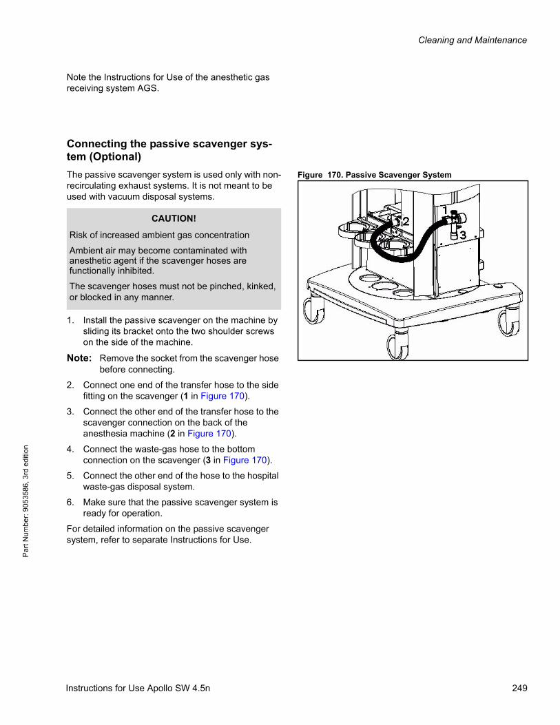
Cleaning and Maintenance
Par
t Num
ber:
905
3586
, 3rd
edi
tion
Note the Instructions for Use of the anesthetic gas receiving system AGS.
Connecting the passive scavenger sys-tem (Optional)
Figure 170. Passive Scavenger SystemThe passive scavenger system is used only with non-recirculating exhaust systems. It is not meant to be used with vacuum disposal systems.
1. Install the passive scavenger on the machine by sliding its bracket onto the two shoulder screws on the side of the machine.
Note: Remove the socket from the scavenger hose before connecting.
2. Connect one end of the transfer hose to the side fitting on the scavenger (1 in Figure 170).
3. Connect the other end of the transfer hose to the scavenger connection on the back of the anesthesia machine (2 in Figure 170).
4. Connect the waste-gas hose to the bottom connection on the scavenger (3 in Figure 170).
5. Connect the other end of the hose to the hospital waste-gas disposal system.
6. Make sure that the passive scavenger system is ready for operation.
For detailed information on the passive scavenger system, refer to separate Instructions for Use.
CAUTION!
Risk of increased ambient gas concentration
Ambient air may become contaminated with anesthetic agent if the scavenger hoses are functionally inhibited.
The scavenger hoses must not be pinched, kinked, or blocked in any manner.
Instructions for Use Apollo SW 4.5n 249
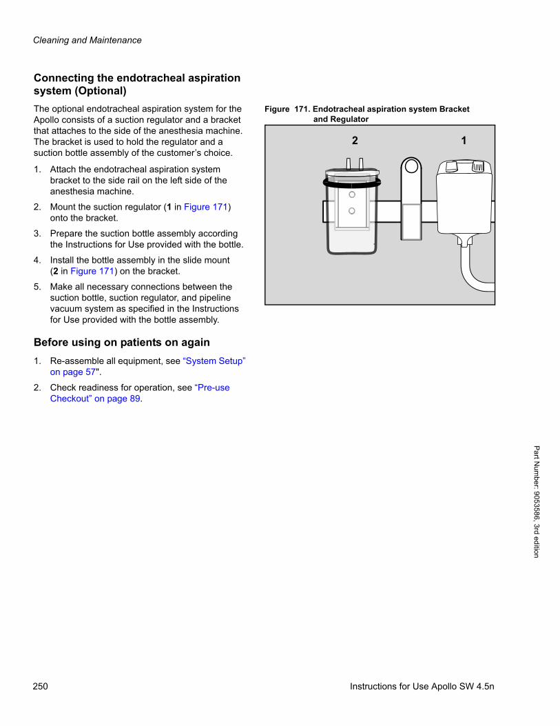
Cleaning and Maintenance
Pa
rt Num
ber: 905358
6, 3rd edition
Connecting the endotracheal aspiration system (Optional)
Figure 171. Endotracheal aspiration system Bracketand Regulator
The optional endotracheal aspiration system for the Apollo consists of a suction regulator and a bracket that attaches to the side of the anesthesia machine. The bracket is used to hold the regulator and a suction bottle assembly of the customer’s choice.
1. Attach the endotracheal aspiration system bracket to the side rail on the left side of the anesthesia machine.
2. Mount the suction regulator (1 in Figure 171) onto the bracket.
3. Prepare the suction bottle assembly according the Instructions for Use provided with the bottle.
4. Install the bottle assembly in the slide mount(2 in Figure 171) on the bracket.
5. Make all necessary connections between the suction bottle, suction regulator, and pipeline vacuum system as specified in the Instructions for Use provided with the bottle assembly.
Before using on patients on again
1. Re-assemble all equipment, see “System Setup” on page 57".
2. Check readiness for operation, see “Pre-use Checkout” on page 89.
12
250 Instructions for Use Apollo SW 4.5n
Cleaning and Maintenance
Par
t Num
ber:
905
3586
, 3rd
edi
tion
Maintenance
Overview
This chapter describes the maintenance measures required to maintain the proper functioning of the medical device. Maintenance measures must be performed by the personnel responsible.
Note: Risk of patient injuryCarrying out maintenance during ventilation will put the patient at risk.Maintenance must only be carried out when a patient is not connected to the device.
Definition ot maintenance concepts
WARNING!
Risk of infection
Users and service personnel can become infected with pathogenic germs.
Disinfect and clean device or device parts before any maintenance measures and also before returning the medical device for repair.
WARNING!
Risk of electric shock
Current-carrying components are located under the cover.
Do not remove the cover.
Maintenance measures must be performed by the personnel responsible. Dräger recommends DrägerService to perform these measures.
Concept Definition
Maintenance All measures (inspection, preventive maintenance, repair) intended to maintain and restore the functional condition of a medical device
Inspection Measures intended to determine and assess the actual state of a medical device
Preventive maintenance Recurrent specified measures intended to maintain the functional condition of a medical device
Repair Measures intended to restore the functional condition of a medical device after a device malfunction
Instructions for Use Apollo SW 4.5n 251
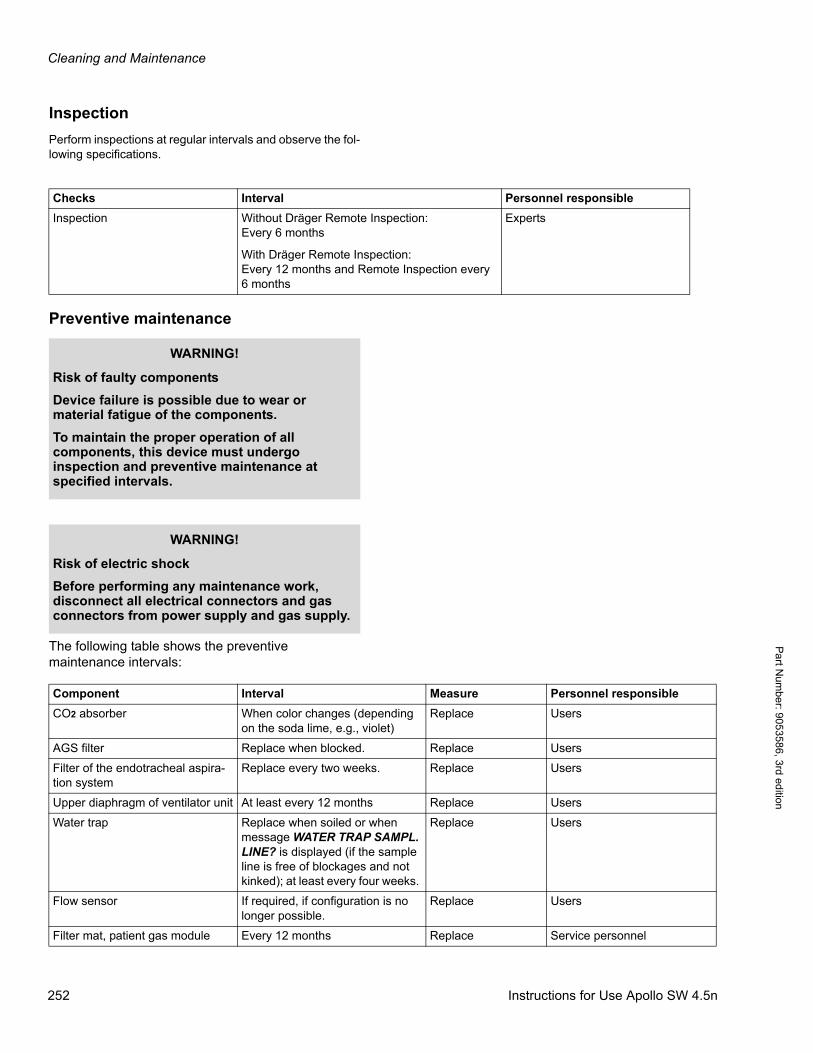
Cleaning and Maintenance
Pa
rt Num
ber: 905358
6, 3rd edition
Inspection
Perform inspections at regular intervals and observe the fol-lowing specifications.
Preventive maintenance
The following table shows the preventive maintenance intervals:
Checks Interval Personnel responsible
Inspection Without Dräger Remote Inspection: Every 6 months
With Dräger Remote Inspection: Every 12 months and Remote Inspection every 6 months
Experts
WARNING!
Risk of faulty components
Device failure is possible due to wear or material fatigue of the components.
To maintain the proper operation of all components, this device must undergo inspection and preventive maintenance at specified intervals.
WARNING!
Risk of electric shock
Before performing any maintenance work, disconnect all electrical connectors and gas connectors from power supply and gas supply.
Component Interval Measure Personnel responsible
CO2 absorber When color changes (depending on the soda lime, e.g., violet)
Replace Users
AGS filter Replace when blocked. Replace Users
Filter of the endotracheal aspira-tion system
Replace every two weeks. Replace Users
Upper diaphragm of ventilator unit At least every 12 months Replace Users
Water trap Replace when soiled or when message WATER TRAP SAMPL. LINE? is displayed (if the sample line is free of blockages and not kinked); at least every four weeks.
Replace Users
Flow sensor If required, if configuration is no longer possible.
Replace Users
Filter mat, patient gas module Every 12 months Replace Service personnel
252 Instructions for Use Apollo SW 4.5n
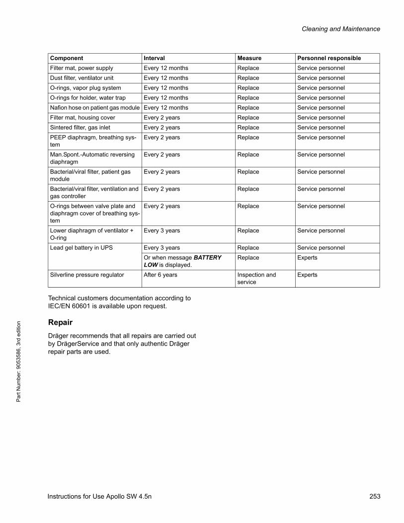
Cleaning and Maintenance
Par
t Num
ber:
905
3586
, 3rd
edi
tion
Technical customers documentation according to IEC/EN 60601 is available upon request.
Repair
Dräger recommends that all repairs are carried out by DrägerService and that only authentic Dräger repair parts are used.
Filter mat, power supply Every 12 months Replace Service personnel
Dust filter, ventilator unit Every 12 months Replace Service personnel
O-rings, vapor plug system Every 12 months Replace Service personnel
O-rings for holder, water trap Every 12 months Replace Service personnel
Nafion hose on patient gas module Every 12 months Replace Service personnel
Filter mat, housing cover Every 2 years Replace Service personnel
Sintered filter, gas inlet Every 2 years Replace Service personnel
PEEP diaphragm, breathing sys-tem
Every 2 years Replace Service personnel
Man.Spont.-Automatic reversing diaphragm
Every 2 years Replace Service personnel
Bacterial/viral filter, patient gas module
Every 2 years Replace Service personnel
Bacterial/viral filter, ventilation and gas controller
Every 2 years Replace Service personnel
O-rings between valve plate and diaphragm cover of breathing sys-tem
Every 2 years Replace Service personnel
Lower diaphragm of ventilator + O-ring
Every 3 years Replace Service personnel
Lead gel battery in UPS Every 3 years Replace Service personnel
Or when message BATTERY LOW is displayed.
Replace Experts
Silverline pressure regulator After 6 years Inspection and service
Experts
Component Interval Measure Personnel responsible
Instructions for Use Apollo SW 4.5n 253
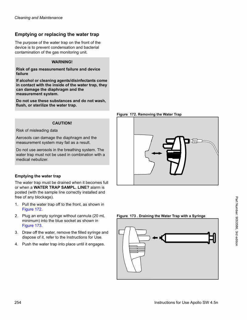
Cleaning and Maintenance
Pa
rt Num
ber: 905358
6, 3rd edition
Emptying or replacing the water trap
The purpose of the water trap on the front of the device is to prevent condensation and bacterial contamination of the gas monitoring unit.
Figure 172. Removing the Water Trap
Emptying the water trap
The water trap must be drained when it becomes full or when a WATER TRAP SAMPL. LINE? alarm is posted (with the sample line correctly installed and free of any blockage).
1. Pull the water trap off to the front, as shown in Figure 172.
Figure 173 . Draining the Water Trap with a Syringe2. Plug an empty syringe without cannula (20 mL minimum) into the blue socket as shown in Figure 173.
3. Draw off the water, remove the filled syringe and dispose of it, refer to the Instructions for Use.
4. Push the water trap into place until it engages.
WARNING!
Risk of gas measurement failure and device failure
If alcohol or cleaning agents/disinfectants come in contact with the inside of the water trap, they can damage the diaphragm and the measurement system.
Do not use these substances and do not wash, flush, or sterilize the water trap.
CAUTION!
Risk of misleading data
Aerosols can damage the diaphragm and the measurement system may fail as a result.
Do not use aerosols in the breathing system. The water trap must not be used in combination with a medical nebulizer.
254 Instructions for Use Apollo SW 4.5n
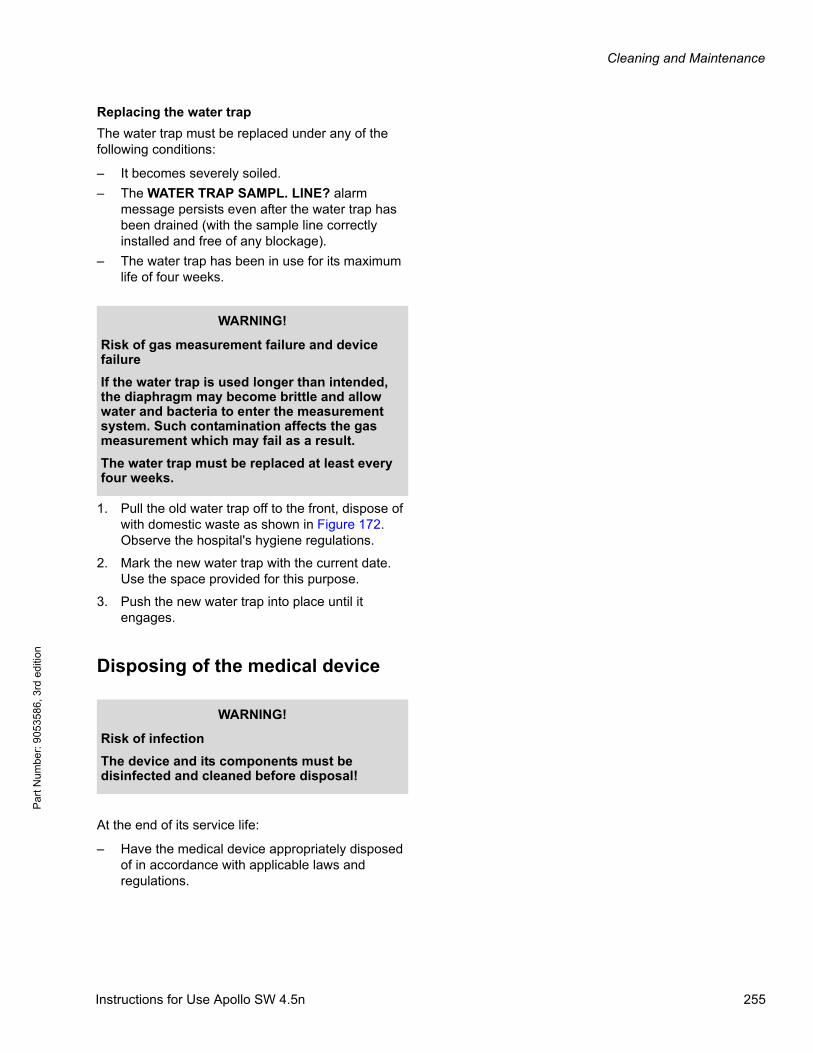
Cleaning and Maintenance
Par
t Num
ber:
905
3586
, 3rd
edi
tion
Replacing the water trap
The water trap must be replaced under any of the following conditions:
– It becomes severely soiled.
– The WATER TRAP SAMPL. LINE? alarm message persists even after the water trap has been drained (with the sample line correctly installed and free of any blockage).
– The water trap has been in use for its maximum life of four weeks.
1. Pull the old water trap off to the front, dispose of with domestic waste as shown in Figure 172. Observe the hospital's hygiene regulations.
2. Mark the new water trap with the current date. Use the space provided for this purpose.
3. Push the new water trap into place until it engages.
Disposing of the medical device
At the end of its service life:
– Have the medical device appropriately disposed of in accordance with applicable laws and regulations.
WARNING!
Risk of gas measurement failure and device failure
If the water trap is used longer than intended, the diaphragm may become brittle and allow water and bacteria to enter the measurement system. Such contamination affects the gas measurement which may fail as a result.
The water trap must be replaced at least every four weeks.
WARNING!
Risk of infection
The device and its components must be disinfected and cleaned before disposal!
Instructions for Use Apollo SW 4.5n 255

Cleaning and Maintenance
Par
t Num
ber:
905
3586
, 3rd
edi
tion
Disposing of non-rechargeable batteries
The battery of this medical device contains pollutant substances.
1. Do not recharge batteries.
2. Observe the applicable laws and regulations for battery disposal.
WARNING!
Risk of explosion and of chemical burns
Improper handling of batteries can result in explosions and chemical burns.
Do not throw batteries into fire. Do not force batteries open.
Instructions for Use Apollo SW 4.5n 256

Troubleshooting
Par
t Num
ber:
905
3586
, 3rd
edi
tion
Troubleshooting
ContentsOverview . . . . . . . . . . . . . . . . . . . . . . . . . . . . . . . . . . . . . . . . . . . . . . . . . . . . . . . . . . . . . . . . . . . . . . . . . . . . . . 259
Power failure . . . . . . . . . . . . . . . . . . . . . . . . . . . . . . . . . . . . . . . . . . . . . . . . . . . . . . . . . . . . . . . . . . . . . . . . . . . 259
Gas failure . . . . . . . . . . . . . . . . . . . . . . . . . . . . . . . . . . . . . . . . . . . . . . . . . . . . . . . . . . . . . . . . . . . . . . . . . . . . . 260
Ventilator failure . . . . . . . . . . . . . . . . . . . . . . . . . . . . . . . . . . . . . . . . . . . . . . . . . . . . . . . . . . . . . . . . . . . . . . . . 262
Fresh-gas delivery failure . . . . . . . . . . . . . . . . . . . . . . . . . . . . . . . . . . . . . . . . . . . . . . . . . . . . . . . . . . . . . . . . 263
Ventilator and fresh-gas delivery failure . . . . . . . . . . . . . . . . . . . . . . . . . . . . . . . . . . . . . . . . . . . . . . . . . . . . 264
Gas measurement failure . . . . . . . . . . . . . . . . . . . . . . . . . . . . . . . . . . . . . . . . . . . . . . . . . . . . . . . . . . . . . . . . . 264
Display failure . . . . . . . . . . . . . . . . . . . . . . . . . . . . . . . . . . . . . . . . . . . . . . . . . . . . . . . . . . . . . . . . . . . . . . . . . . 265
User interface failure . . . . . . . . . . . . . . . . . . . . . . . . . . . . . . . . . . . . . . . . . . . . . . . . . . . . . . . . . . . . . . . . . . . . 265
System failure . . . . . . . . . . . . . . . . . . . . . . . . . . . . . . . . . . . . . . . . . . . . . . . . . . . . . . . . . . . . . . . . . . . . . . . . . . 265
Alarm - Cause - Remedy . . . . . . . . . . . . . . . . . . . . . . . . . . . . . . . . . . . . . . . . . . . . . . . . . . . . . . . . . . . . . . . . . 267
Instructions for Use Apollo SW 4.5n 257

Troubleshooting
Pa
rt Num
ber: 905358
6, 3rd edition
This page intentionally left blank.
258 Instructions for Use Apollo SW 4.5n
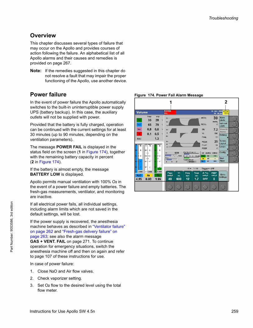
Troubleshooting
Par
t Num
ber:
905
3586
, 3rd
edi
tion
OverviewThis chapter discusses several types of failure that may occur on the Apollo and provides courses of action following the failure. An alphabetical list of all Apollo alarms and their causes and remedies is provided on page 267.
Note: If the remedies suggested in this chapter do not resolve a fault that may impair the proper functioning of the Apollo, use another device.
Figure 174. Power Fail Alarm MessagePower failureIn the event of power failure the Apollo automatically switches to the built-in uninterruptible power supply UPS (battery backup). In this case, the auxiliary outlets will not be supplied with power.
Provided that the battery is fully charged, operation can be continued with the current settings for at least 30 minutes (up to 90 minutes, depending on the ventilation parameters).
The message POWER FAIL is displayed in the status field on the screen (1 in Figure 174), together with the remaining battery capacity in percent(2 in Figure 174).
If the battery is almost empty, the message BATTERY LOW is displayed.
Apollo permits manual ventilation with 100% O2 in the event of a power failure and empty batteries. The fresh-gas measurements, ventilator, and monitoring are inactive.
If all electrical power fails, all individual settings, including alarm limits which are not saved in the default settings, will be lost.
If the power supply is recovered, the anesthesia machine behaves as described in “Ventilator failure” on page 262 and “Fresh-gas delivery failure” on page 263; see also the alarm messageGAS + VENT. FAIL on page 271. To continue operation for emergency situations, switch the anesthesia machine off and then on again and refer to page 107 of these instructions for use.
In case of power failure:
1. Close N2O and Air flow valves.
2. Check vaporizer setting.
3. Set O2 flow to the desired level using the total flow meter.
1 2
Instructions for Use Apollo SW 4.5n 259
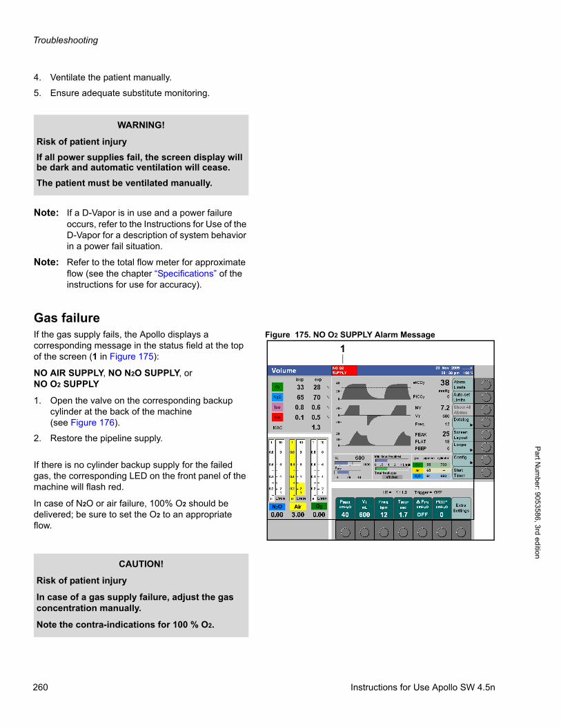
Troubleshooting
Pa
rt Num
ber: 905358
6, 3rd edition
4. Ventilate the patient manually.
5. Ensure adequate substitute monitoring.
Note: If a D-Vapor is in use and a power failure occurs, refer to the Instructions for Use of the D-Vapor for a description of system behavior in a power fail situation.
Note: Refer to the total flow meter for approximate flow (see the chapter “Specifications” of the instructions for use for accuracy).
Gas failureFigure 175. NO O2 SUPPLY Alarm MessageIf the gas supply fails, the Apollo displays a
corresponding message in the status field at the top of the screen (1 in Figure 175):
NO AIR SUPPLY, NO N2O SUPPLY, orNO O2 SUPPLY
1. Open the valve on the corresponding backup cylinder at the back of the machine(see Figure 176).
2. Restore the pipeline supply.
If there is no cylinder backup supply for the failed gas, the corresponding LED on the front panel of the machine will flash red.
In case of N2O or air failure, 100% O2 should be delivered; be sure to set the O2 to an appropriate flow.
WARNING!
Risk of patient injury
If all power supplies fail, the screen display will be dark and automatic ventilation will cease.
The patient must be ventilated manually.
1
CAUTION!
Risk of patient injury
In case of a gas supply failure, adjust the gas concentration manually.
Note the contra-indications for 100 % O2.
260 Instructions for Use Apollo SW 4.5n
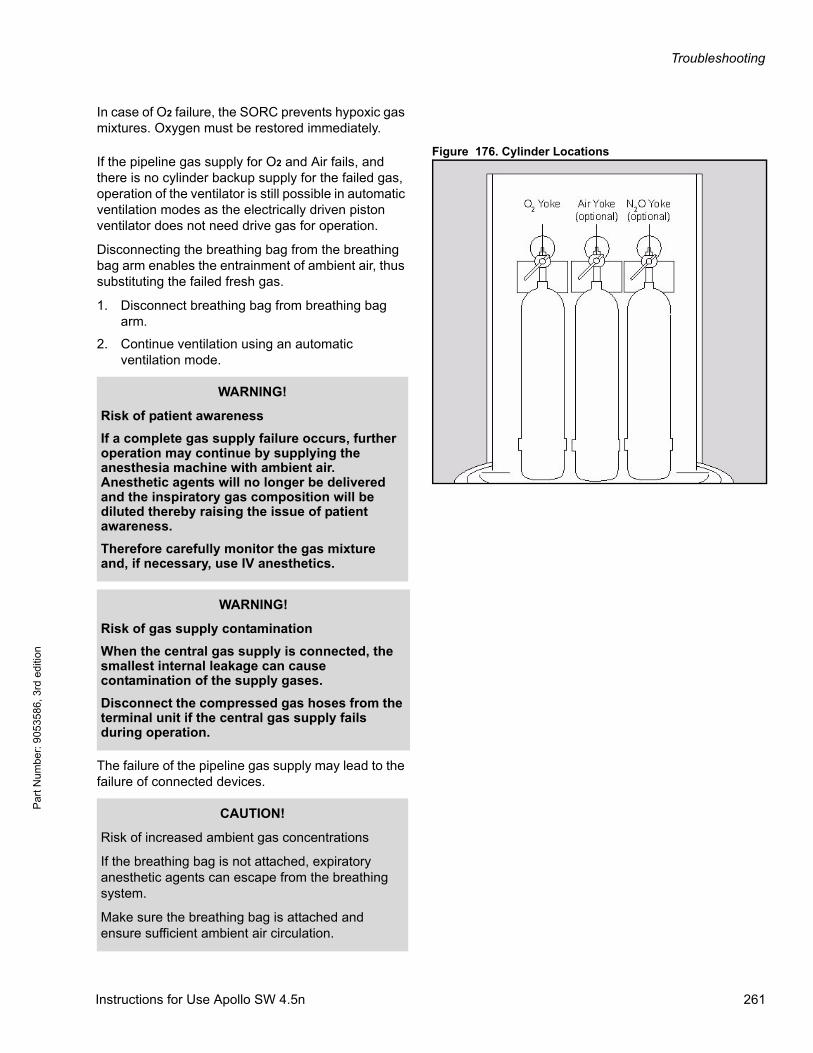
Troubleshooting
Par
t Num
ber:
905
3586
, 3rd
edi
tion
In case of O2 failure, the SORC prevents hypoxic gas mixtures. Oxygen must be restored immediately.
Figure 176. Cylinder LocationsIf the pipeline gas supply for O2 and Air fails, and there is no cylinder backup supply for the failed gas, operation of the ventilator is still possible in automatic ventilation modes as the electrically driven piston ventilator does not need drive gas for operation.
Disconnecting the breathing bag from the breathing bag arm enables the entrainment of ambient air, thus substituting the failed fresh gas.
1. Disconnect breathing bag from breathing bag arm.
2. Continue ventilation using an automatic ventilation mode.
The failure of the pipeline gas supply may lead to the failure of connected devices.
WARNING!
Risk of patient awareness
If a complete gas supply failure occurs, further operation may continue by supplying the anesthesia machine with ambient air. Anesthetic agents will no longer be delivered and the inspiratory gas composition will be diluted thereby raising the issue of patient awareness.
Therefore carefully monitor the gas mixture and, if necessary, use IV anesthetics.
WARNING!
Risk of gas supply contamination
When the central gas supply is connected, the smallest internal leakage can cause contamination of the supply gases.
Disconnect the compressed gas hoses from the terminal unit if the central gas supply fails during operation.
CAUTION!
Risk of increased ambient gas concentrations
If the breathing bag is not attached, expiratory anesthetic agents can escape from the breathing system.
Make sure the breathing bag is attached and ensure sufficient ambient air circulation.
Instructions for Use Apollo SW 4.5n 261
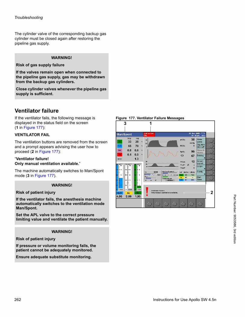
Troubleshooting
Pa
rt Num
ber: 905358
6, 3rd edition
The cylinder valve of the corresponding backup gas cylinder must be closed again after restoring the pipeline gas supply.
Ventilator failureFigure 177. Ventilator Failure MessagesIf the ventilator fails, the following message is
displayed in the status field on the screen(1 in Figure 177):
VENTILATOR FAIL
The ventilation buttons are removed from the screen and a prompt appears advising the user how to proceed (2 in Figure 177):
“Ventilator failure!Only manual ventilation available.”
The machine automatically switches to Man/Spont mode (3 in Figure 177).
WARNING!
Risk of gas supply failure
If the valves remain open when connected to the pipeline gas supply, gas may be withdrawn from the backup gas cylinders.
Close cylinder valves whenever the pipeline gas supply is sufficient.
1
2
3
WARNING!
Risk of patient injury
If the ventilator fails, the anesthesia machine automatically switches to the ventilation mode Man/Spont.
Set the APL valve to the correct pressure limiting value and ventilate the patient manually.
WARNING!
Risk of patient injury
If pressure or volume monitoring fails, the patient cannot be adequately monitored.
Ensure adequate substitute monitoring.
262 Instructions for Use Apollo SW 4.5n
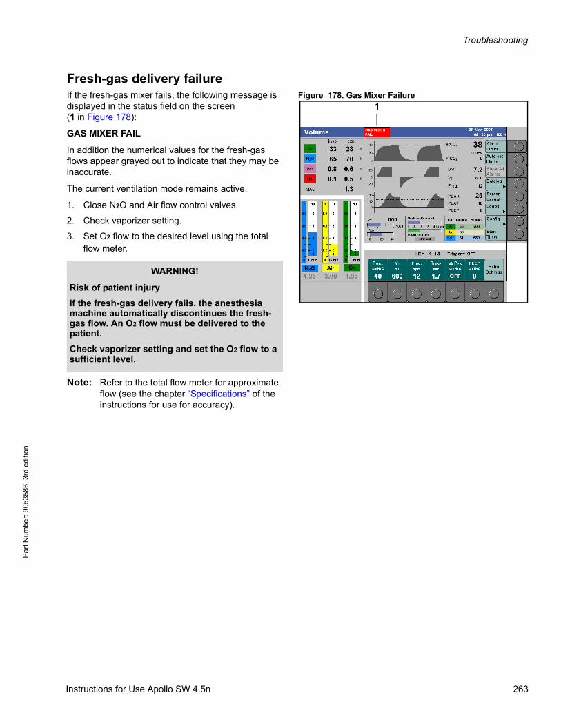
Troubleshooting
Par
t Num
ber:
905
3586
, 3rd
edi
tion
Fresh-gas delivery failureFigure 178. Gas Mixer Failure If the fresh-gas mixer fails, the following message is
displayed in the status field on the screen(1 in Figure 178):
GAS MIXER FAIL
In addition the numerical values for the fresh-gas flows appear grayed out to indicate that they may be inaccurate.
The current ventilation mode remains active.
1. Close N2O and Air flow control valves.
2. Check vaporizer setting.
3. Set O2 flow to the desired level using the total flow meter.
Note: Refer to the total flow meter for approximate flow (see the chapter “Specifications” of the instructions for use for accuracy).
1
WARNING!
Risk of patient injury
If the fresh-gas delivery fails, the anesthesia machine automatically discontinues the fresh-gas flow. An O2 flow must be delivered to the patient.
Check vaporizer setting and set the O2 flow to a sufficient level.
Instructions for Use Apollo SW 4.5n 263
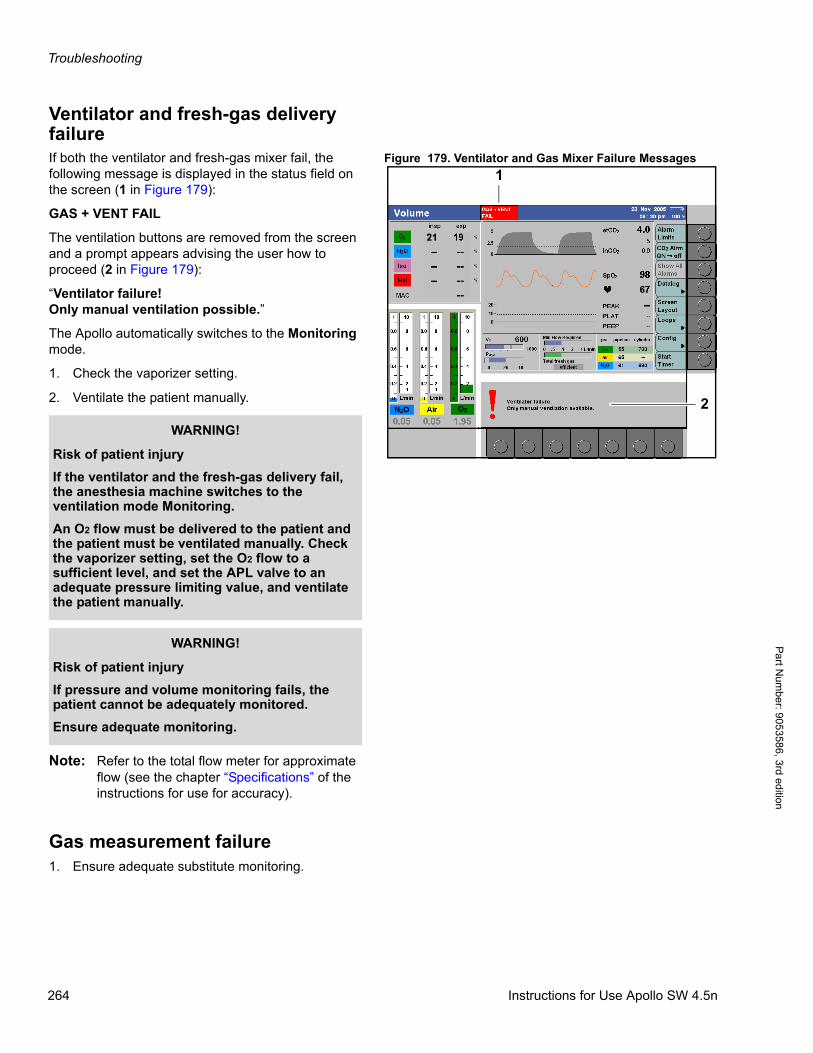
Troubleshooting
Pa
rt Num
ber: 905358
6, 3rd edition
Ventilator and fresh-gas delivery failure
Figure 179. Ventilator and Gas Mixer Failure MessagesIf both the ventilator and fresh-gas mixer fail, the following message is displayed in the status field on the screen (1 in Figure 179):
GAS + VENT FAIL
The ventilation buttons are removed from the screen and a prompt appears advising the user how to proceed (2 in Figure 179):
“Ventilator failure!Only manual ventilation possible.”
The Apollo automatically switches to the Monitoring mode.
1. Check the vaporizer setting.
2. Ventilate the patient manually.
Note: Refer to the total flow meter for approximate flow (see the chapter “Specifications” of the instructions for use for accuracy).
Gas measurement failure1. Ensure adequate substitute monitoring.
1
2
WARNING!
Risk of patient injury
If the ventilator and the fresh-gas delivery fail, the anesthesia machine switches to the ventilation mode Monitoring.
An O2 flow must be delivered to the patient and the patient must be ventilated manually. Check the vaporizer setting, set the O2 flow to a sufficient level, and set the APL valve to an adequate pressure limiting value, and ventilate the patient manually.
WARNING!
Risk of patient injury
If pressure and volume monitoring fails, the patient cannot be adequately monitored.
Ensure adequate monitoring.
264 Instructions for Use Apollo SW 4.5n
Troubleshooting
Par
t Num
ber:
905
3586
, 3rd
edi
tion
Display failureIf the screen display fails:
1. Switch off the machine.
2. Set O2 flow to the desired level using the total flow meter.
3. Check the vaporizer setting.
4. Ventilate the patient manually.
5. Ensure adequate substitute monitoring.
User interface failureIf the keypads, rotary knob, or flow control knobs are not operational:
1. Select the monitoring mode (see page 177).
2. Ventilate the patient manually.
Note: Observe the total flow meter for approximate flow (see the chapter “Specifications” of the instructions for use for accuracy).
System failureIf the system no longer responds to an action:
1. Ventilate the patient by hand.
2. Switch the machine off and on again.
3. Cancel the self test.
If the system has failed completely:
1. Switch the Apollo off.
In both cases, to ensure alternative delivery of 100 % O2 and anesthetic agent:
1. Check the vaporizer setting.
2. Close all flow controls (except O2), and run 100% O2
Instructions for Use Apollo SW 4.5n 265
Troubleshooting
Pa
rt Num
ber: 905358
6, 3rd edition
WARNING!
Risk of patient injury
If the breathing bag does not fill with fresh gas, the patient cannot be adequately ventilated.
Check the oxygen supply, open cylinder valves if necessary.
If fresh gas is still not delivered or manual ventilation is not possible, close all flow controls.
Disconnect the anesthesia machine from the patient and use an alternative method of ventilation.
266 Instructions for Use Apollo SW 4.5n
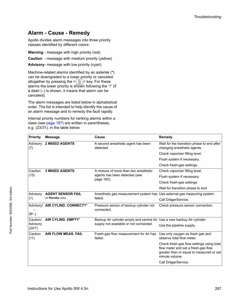
Troubleshooting
Par
t Num
ber:
905
3586
, 3rd
edi
tion
Alarm - Cause - RemedyApollo divides alarm messages into three priority classes identified by different colors:
Machine-related alarms identified by an asterisk (*) can be downgraded to a lower priority or canceled altogether by pressing the > < key. For these alarms the lower priority is shown following the “/” (if a dash (–) is shown, it means that alarm can be canceled).
The alarm messages are listed below in alphabetical order. The list is intended to help identify the cause of an alarm message and to remedy the fault rapidly.
Internal priority numbers for ranking alarms within a class (see page 187) are written in parentheses, e.g. (23/31), in the table below.
Warning - message with high priority (red)
Caution - message with medium priority (yellow)
Advisory- message with low priority (cyan)
Priority Message Cause Remedy
Advisory(7)
2 MIXED AGENTS A second anesthetic agent has been detected.
Wait for the transition phase to end after changing anesthetic agents.
Check vaporizer filling level.
Flush system if necessary.
Check fresh-gas settings.
Caution(15)
3 MIXED AGENTS A mixture of more than two anesthetic agents has been detected (see page 165).
Check vaporizer filling level.
Flush system if necessary.
Check fresh-gas settings.
Wait for transition phase to end.
Advisory(1)
AGENT SENSOR FAIL(in Standby only)
Anesthetic gas measurement system has failed.
Use external gas measuring system.
Call DrägerService.
Advisory/ –(8/–)
AIR CYLIND. CONNECT?* Pressure sensor of backup cylinder not connected.
Check pressure sensor connection.
Caution/Advisory(24/7)
AIR CYLIND. EMPTY* Backup Air cylinder empty and central Air supply not available or not connected.
Use a new backup Air cylinder.
Use the pipeline supply.
Caution(11)
AIR FLOW MEAS. FAIL Fresh-gas flow measurement for Air has failed.
Use only oxygen as fresh gas and observe total flow meter.
Check fresh-gas flow settings using total flow meter and set a fresh-gas flow greater than or equal to measured or set minute volume.
Call DrägerService.
Instructions for Use Apollo SW 4.5n 267

Troubleshooting
Pa
rt Num
ber: 905358
6, 3rd edition
Advisory(10)
AIR PIPELINE FAIL Compressed Air supply has failed. Open optional backup Air cylinder.
Check piped medical Air supply.
Pipeline supply hose not connected or kinked.
Check connection to piped medical Air supply.
Optional Air cylinder is empty or closed. Connect a full Air cylinder or open the cylinder valve.
Compressed Air compressor has failed. Check compressor.
Caution(24)Warning(31)
APNEA Priority in accordance with maximum priority of the individual alarms.
Breathing/ventilation has stopped (detected by pressure, volume, and CO2 monitoring).
Patient must immediately be ventilated manually!
Check patient's spontaneous breathing ability.
Check ventilator settings.
Check fresh-gas setting.
Maske sure everything is connected.
Check hose system and tube.
Advisory(10)Caution(24)Warning(31)
APNEA CO2 Apnea alarms are graded in time (see page 210).
In automatic ventilation modes:Caution = 0 to 30 sec.Warning = >30 sec.
In ventilation modes Man/Spont, Pressure Support, Aux CGO:Advisory = 0 to 30 sec.Caution = 31 to 60 sec.Warning = >60 sec.
Sample line not connected. Check sample line.
No spontaneous breathing. Patient must immediately be ventilated manually!
Check patient's spontaneous breathing ability.
Make sure everything is connected.
Check hose system and tube.
Breathing/ventilation has stopped. Patient must immediately be ventilated manually!
Check ventilator setting.
Priority Message Cause Remedy
268 Instructions for Use Apollo SW 4.5n
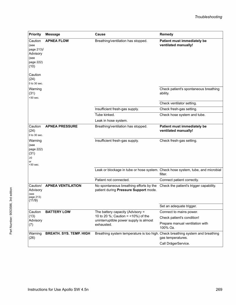
Troubleshooting
Par
t Num
ber:
905
3586
, 3rd
edi
tion
Caution(see page 213)/ Advisory(see page 222)(10)
Caution(24)0 to 30 sec.
APNEA FLOW Breathing/ventilation has stopped. Patient must immediately be ventilated manually!
Warning(31)>30 sec.
Check patient's spontaneous breathing ability.
Check ventilator setting.
Insufficient fresh-gas supply. Check fresh-gas setting.
Tube kinked.
Leak in hose system.
Check hose system and tube.
Caution(24)0 to 30 sec.
APNEA PRESSURE Breathing/ventilation has stopped. Patient must immediately be ventilated manually!
Warning(see page 222)(31)≥0or>30 sec.
Insufficient fresh-gas supply. Check fresh-gas setting.
Leak or blockage in tube or hose system. Check hose system, tube, and microbial filter.
Patient not connected. Connect patient correctly.
Caution/Advisory(see page 213)(11/9)
APNEA VENTILATION No spontaneous breathing efforts by the patient during Pressure Support mode.
Check the patient's trigger capability.
Set an adequate trigger.
Caution(13)Advisory(7)
BATTERY LOW The battery capacity (Advisory = 10 to 20 %; Caution = <10%) of the uninterruptible power supply is almost exhausted.
Connect to mains power.
Check patient's condition!
Prepare manual ventilation with100% O2.
Warning(26)
BREATH. SYS. TEMP. HIGH Breathing system temperature is too high. Check breathing system and breathing gas temperatures.
Call DrägerService.
Priority Message Cause Remedy
Instructions for Use Apollo SW 4.5n 269
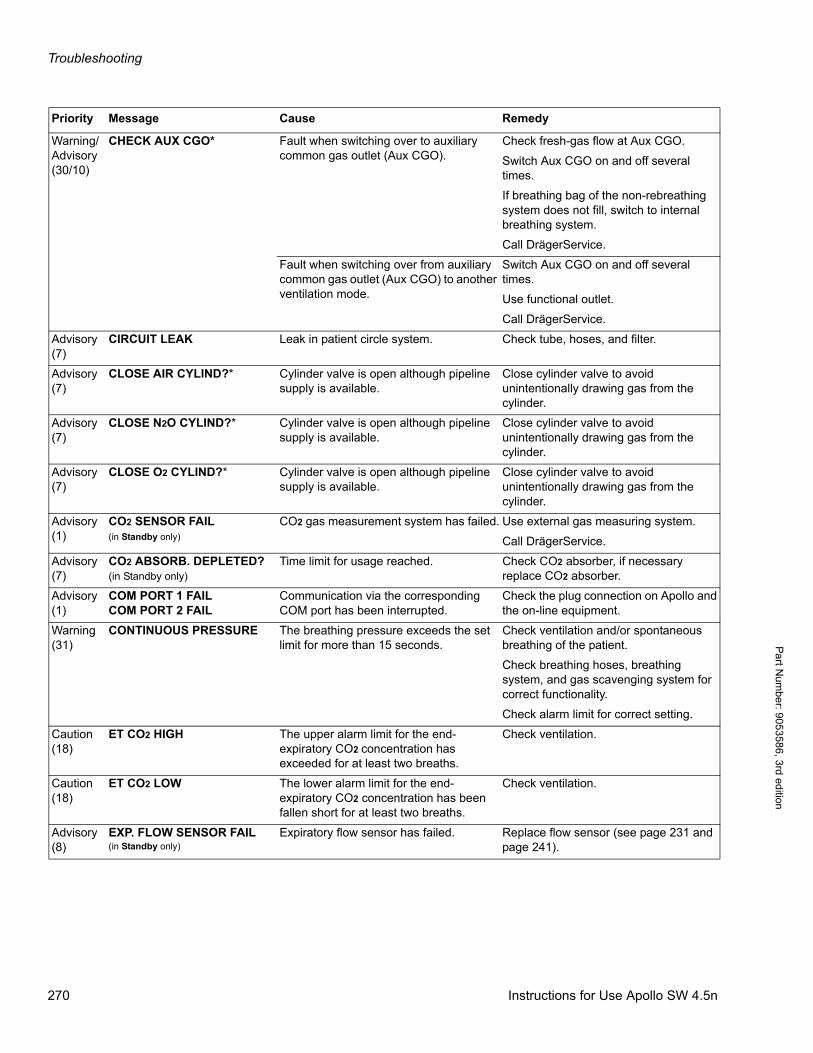
Troubleshooting
Pa
rt Num
ber: 905358
6, 3rd edition
Warning/Advisory(30/10)
CHECK AUX CGO* Fault when switching over to auxiliary common gas outlet (Aux CGO).
Check fresh-gas flow at Aux CGO.
Switch Aux CGO on and off several times.
If breathing bag of the non-rebreathing system does not fill, switch to internal breathing system.
Call DrägerService.
Fault when switching over from auxiliary common gas outlet (Aux CGO) to another ventilation mode.
Switch Aux CGO on and off several times.
Use functional outlet.
Call DrägerService.
Advisory(7)
CIRCUIT LEAK Leak in patient circle system. Check tube, hoses, and filter.
Advisory(7)
CLOSE AIR CYLIND?* Cylinder valve is open although pipeline supply is available.
Close cylinder valve to avoid unintentionally drawing gas from the cylinder.
Advisory(7)
CLOSE N2O CYLIND?* Cylinder valve is open although pipeline supply is available.
Close cylinder valve to avoid unintentionally drawing gas from the cylinder.
Advisory(7)
CLOSE O2 CYLIND?* Cylinder valve is open although pipeline supply is available.
Close cylinder valve to avoid unintentionally drawing gas from the cylinder.
Advisory(1)
CO2 SENSOR FAIL(in Standby only)
CO2 gas measurement system has failed. Use external gas measuring system.
Call DrägerService.
Advisory(7)
CO2 ABSORB. DEPLETED?(in Standby only)
Time limit for usage reached. Check CO2 absorber, if necessary replace CO2 absorber.
Advisory(1)
COM PORT 1 FAILCOM PORT 2 FAIL
Communication via the corresponding COM port has been interrupted.
Check the plug connection on Apollo and the on-line equipment.
Warning(31)
CONTINUOUS PRESSURE The breathing pressure exceeds the set limit for more than 15 seconds.
Check ventilation and/or spontaneous breathing of the patient.
Check breathing hoses, breathing system, and gas scavenging system for correct functionality.
Check alarm limit for correct setting.
Caution(18)
ET CO2 HIGH The upper alarm limit for the end-expiratory CO2 concentration has exceeded for at least two breaths.
Check ventilation.
Caution(18)
ET CO2 LOW The lower alarm limit for the end-expiratory CO2 concentration has been fallen short for at least two breaths.
Check ventilation.
Advisory(8)
EXP. FLOW SENSOR FAIL(in Standby only)
Expiratory flow sensor has failed. Replace flow sensor (see page 231 and page 241).
Priority Message Cause Remedy
270 Instructions for Use Apollo SW 4.5n
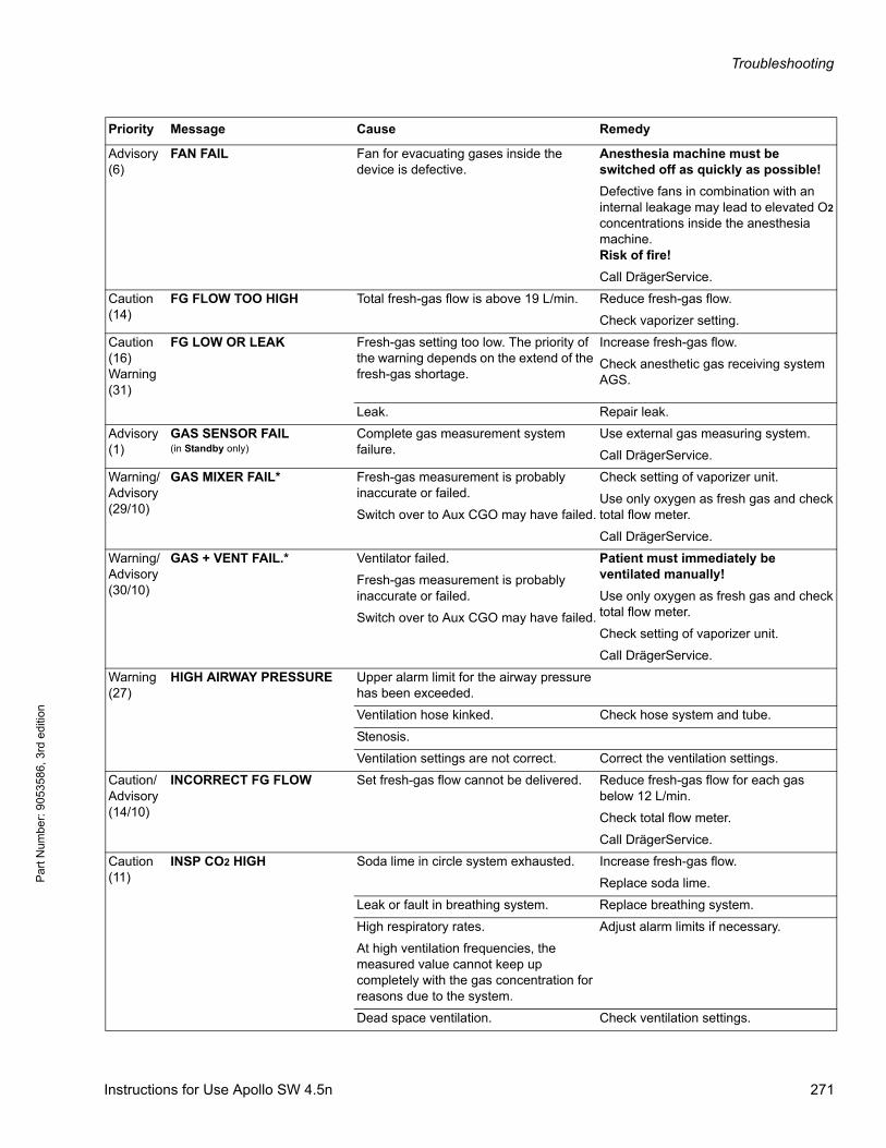
Troubleshooting
Par
t Num
ber:
905
3586
, 3rd
edi
tion
Advisory(6)
FAN FAIL Fan for evacuating gases inside the device is defective.
Anesthesia machine must be switched off as quickly as possible!
Defective fans in combination with an internal leakage may lead to elevated O2 concentrations inside the anesthesia machine.Risk of fire!
Call DrägerService.
Caution(14)
FG FLOW TOO HIGH Total fresh-gas flow is above 19 L/min. Reduce fresh-gas flow.
Check vaporizer setting.
Caution(16)Warning(31)
FG LOW OR LEAK Fresh-gas setting too low. The priority of the warning depends on the extend of the fresh-gas shortage.
Increase fresh-gas flow.
Check anesthetic gas receiving system AGS.
Leak. Repair leak.
Advisory(1)
GAS SENSOR FAIL(in Standby only)
Complete gas measurement system failure.
Use external gas measuring system.
Call DrägerService.
Warning/Advisory(29/10)
GAS MIXER FAIL* Fresh-gas measurement is probably inaccurate or failed.
Switch over to Aux CGO may have failed.
Check setting of vaporizer unit.
Use only oxygen as fresh gas and check total flow meter.
Call DrägerService.
Warning/Advisory(30/10)
GAS + VENT FAIL.* Ventilator failed.
Fresh-gas measurement is probably inaccurate or failed.
Switch over to Aux CGO may have failed.
Patient must immediately be ventilated manually!
Use only oxygen as fresh gas and check total flow meter.
Check setting of vaporizer unit.
Call DrägerService.
Warning(27)
HIGH AIRWAY PRESSURE Upper alarm limit for the airway pressure has been exceeded.
Ventilation hose kinked. Check hose system and tube.
Stenosis.
Ventilation settings are not correct. Correct the ventilation settings.
Caution/Advisory(14/10)
INCORRECT FG FLOW Set fresh-gas flow cannot be delivered. Reduce fresh-gas flow for each gas below 12 L/min.
Check total flow meter.
Call DrägerService.
Caution(11)
INSP CO2 HIGH Soda lime in circle system exhausted. Increase fresh-gas flow.
Replace soda lime.
Leak or fault in breathing system. Replace breathing system.
High respiratory rates.
At high ventilation frequencies, the measured value cannot keep up completely with the gas concentration for reasons due to the system.
Adjust alarm limits if necessary.
Dead space ventilation. Check ventilation settings.
Priority Message Cause Remedy
Instructions for Use Apollo SW 4.5n 271
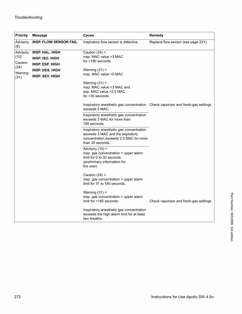
Troubleshooting
Pa
rt Num
ber: 905358
6, 3rd edition
Advisory(8)
INSP. FLOW SENSOR FAIL Inspiratory flow sensor is defective. Replace flow sensor (see page 231).
Advisory(10)
Caution(24)
Warning(31)
INSP. HAL. HIGH
INSP. ISO. HIGH
INSP. ENF. HIGH
INSP. DES. HIGH
INSP. SEV. HIGH
Caution (24) =insp. MAC value >3 MACfor >180 seconds.
Warning (31) =insp. MAC value >5 MAC
Warning (31) =insp. MAC value >3 MAC andexp. MAC value >2.5 MACfor >30 seconds.
Inspiratory anesthetic gas concentration exceeds 5 MAC.
Check vaporizer and fresh-gas settings.
Inspiratory anesthetic gas concentration exceeds 3 MAC for more than 180 seconds.
Inspiratory anesthetic gas concentration exceeds 3 MAC and the expiratory concentration exceeds 2.5 MAC for more than 30 seconds.
Advisory (10) =insp. gas concentration > upper alarm limit for 0 to 30 seconds.(preliminary information forthe user)
Caution (24) =insp. gas concentration > upper alarm limit for 31 to 180 seconds.
Warning (31) =insp. gas concentration > upper alarm limit for >180 seconds.
Inspiratory anesthetic gas concentration exceeds the high alarm limit for at least two breaths.
Check vaporizer and fresh-gas settings.
Priority Message Cause Remedy
272 Instructions for Use Apollo SW 4.5n
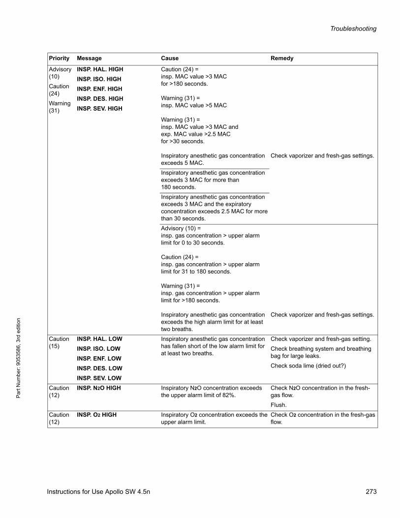
Troubleshooting
Par
t Num
ber:
905
3586
, 3rd
edi
tion
Advisory(10)
Caution(24)
Warning(31)
INSP. HAL. HIGH
INSP. ISO. HIGH
INSP. ENF. HIGH
INSP. DES. HIGH
INSP. SEV. HIGH
Caution (24) =insp. MAC value >3 MACfor >180 seconds.
Warning (31) =insp. MAC value >5 MAC
Warning (31) =insp. MAC value >3 MAC andexp. MAC value >2.5 MACfor >30 seconds.
Inspiratory anesthetic gas concentration exceeds 5 MAC.
Check vaporizer and fresh-gas settings.
Inspiratory anesthetic gas concentration exceeds 3 MAC for more than 180 seconds.
Inspiratory anesthetic gas concentration exceeds 3 MAC and the expiratory concentration exceeds 2.5 MAC for more than 30 seconds.
Advisory (10) =insp. gas concentration > upper alarm limit for 0 to 30 seconds.
Caution (24) =insp. gas concentration > upper alarm limit for 31 to 180 seconds.
Warning (31) =insp. gas concentration > upper alarm limit for >180 seconds.
Inspiratory anesthetic gas concentration exceeds the high alarm limit for at least two breaths.
Check vaporizer and fresh-gas settings.
Caution(15)
INSP. HAL. LOW
INSP. ISO. LOW
INSP. ENF. LOW
INSP. DES. LOW
INSP. SEV. LOW
Inspiratory anesthetic gas concentration has fallen short of the low alarm limit for at least two breaths.
Check vaporizer and fresh-gas setting.
Check breathing system and breathing bag for large leaks.
Check soda lime (dried out?)
Caution(12)
INSP. N2O HIGH Inspiratory N2O concentration exceeds the upper alarm limit of 82%.
Check N2O concentration in the fresh-gas flow.
Flush.
Caution(12)
INSP. O2 HIGH Inspiratory O2 concentration exceeds the upper alarm limit.
Check O2 concentration in the fresh-gas flow.
Priority Message Cause Remedy
Instructions for Use Apollo SW 4.5n 273
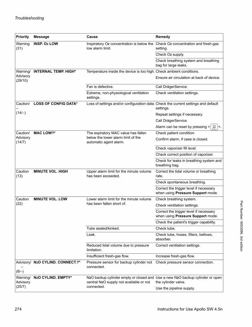
Troubleshooting
Pa
rt Num
ber: 905358
6, 3rd edition
Warning(31)
INSP. O2 LOW Inspiratory O2 concentration is below the low alarm limit.
Check O2 concentration and fresh-gas setting.
Check O2 supply.
Check breathing system and breathing bag for large leaks.
Warning/Advisory(29/10)
INTERNAL TEMP. HIGH* Temperature inside the device is too high. Check ambient conditions.
Ensure air circulation at back of device.
Fan is defective. Call DrägerService.
Extreme, non-physiological ventilation settings.
Check ventilation settings.
Caution/–(14/–)
LOSS OF CONFIG DATA* Loss of settings and/or configuration data. Check the current settings and default settings.
Repeat settings if necessary.
Call DrägerService.
Alarm can be reset by pressing > <.
Caution/Advisory(14/7)
MAC LOW?* The expiratory MAC value has fallen below the lower alarm limit of the automatic agent alarm.
Check patient condition.
Confirm alarm, if case is closed.
Check vaporizer fill level.
Check correct position of vaporizer.
Check for leaks in breathing system and breathing bag.
Caution(13)
MINUTE VOL. HIGH Upper alarm limit for the minute volume has been exceeded.
Correct the tidal volume or breathing rate.
Check spontaneous breathing.
Correct the trigger level if necessary when using Pressure Support mode.
Caution(22)
MINUTE VOL. LOW Lower alarm limit for the minute volume has been fallen short of.
Check breathing system.
Check ventilation settings.
Correct the trigger level if necessary when using Pressure Support mode.
Check the patient's trigger capability.
Tube sealed/kinked. Check tube.
Leak. Check tube, hoses, filters, bellows, absorber.
Reduced tidal volume due to pressure limitation.
Correct ventilation settings.
Insufficient fresh-gas flow. Increase fresh-gas flow.
Advisory/ –(8/–)
N2O CYLIND. CONNECT.?* Pressure sensor for backup cylinder not connected.
Check pressure sensor connection.
Warning/Advisory(25/7)
N2O CYLIND. EMPTY* N2O backup cylinder empty or closed and central N2O supply not available or not connected.
Use a new N2O backup cylinder or open the cylinder valve.
Use the pipeline supply.
Priority Message Cause Remedy
274 Instructions for Use Apollo SW 4.5n
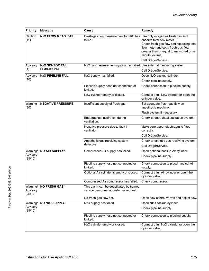
Troubleshooting
Par
t Num
ber:
905
3586
, 3rd
edi
tion
Caution(11)
N2O FLOW MEAS. FAIL Fresh-gas flow measurement for N2O has failed.
Use only oxygen as fresh gas and observe total flow meter.Check fresh-gas flow settings using total flow meter and set a fresh-gas flow greater than or equal to measured or set minute volume.
Call DrägerService.
Advisory(1)
N2O SENSOR FAIL(in Standby only)
N2O gas measurement system has failed. Use external measuring system.
Call DrägerService.
Advisory(10)
N2O PIPELINE FAIL N2O supply has failed. Open N2O backup cylinder.
Check pipeline supply.
Pipeline supply hose not connected or kinked.
Check connection to pipeline supply.
N2O cylinder empty or closed. Connect a full N2O cylinder or open the cylinder valve.
Warning(30)
NEGATIVE PRESSURE Insufficient supply of fresh gas. Set adequate fresh-gas flow on anesthesia machine.
Flush system if necessary.
Endotracheal aspiration during ventilation.
Check endotracheal aspiration system.
Negative pressure due to fault in ventilator.
Make sure upper diaphragm is fitted correctly.
Call DrägerService.
Anesthetic gas receiving system defective.
Check anesthetic gas receiving system.
Call DrägerService.
Warning/ Advisory(25/10)
NO AIR SUPPLY* Compressed Air supply has failed. Open optional backup Air cylinder.
Check pipeline supply.
Pipeline supply hose not connected or kinked.
Check connection to piped medical Air supply.
Optional Air cylinder is empty or closed. Connect a full Air cylinder or open the cylinder valve.
Compressed Air compressor has failed. Check compressor.
Warning/Advisory(26/9)
NO FRESH GAS* This alarm can be deactivated by trained service personnel at customer request.
No fresh-gas flow set. Open flow control valves and adjust flow.
Warning/Advisory(25/10)
NO N2O SUPPLY* N2O supply has failed. Open N2O backup cylinder.
Check pipeline supply.
Pipeline supply hose not connected or kinked.
Check connection to pipeline supply.
N2O cylinder empty or closed. Connect a full N2O cylinder or open the cylinder valve.
Priority Message Cause Remedy
Instructions for Use Apollo SW 4.5n 275
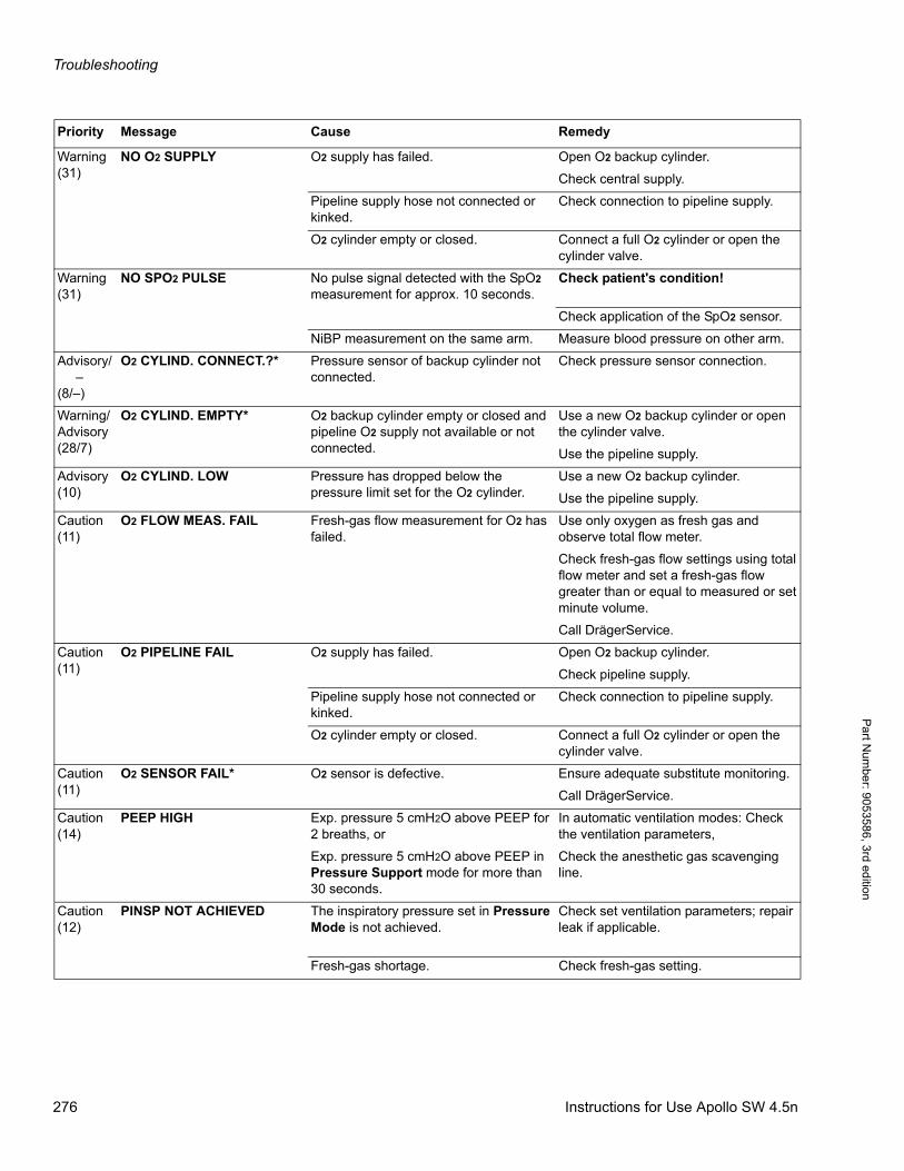
Troubleshooting
Pa
rt Num
ber: 905358
6, 3rd edition
Warning(31)
NO O2 SUPPLY O2 supply has failed. Open O2 backup cylinder.
Check central supply.
Pipeline supply hose not connected or kinked.
Check connection to pipeline supply.
O2 cylinder empty or closed. Connect a full O2 cylinder or open the cylinder valve.
Warning(31)
NO SPO2 PULSE No pulse signal detected with the SpO2 measurement for approx. 10 seconds.
Check patient's condition!
Check application of the SpO2 sensor.
NiBP measurement on the same arm. Measure blood pressure on other arm.
Advisory/ –(8/–)
O2 CYLIND. CONNECT.?* Pressure sensor of backup cylinder not connected.
Check pressure sensor connection.
Warning/Advisory(28/7)
O2 CYLIND. EMPTY* O2 backup cylinder empty or closed and pipeline O2 supply not available or not connected.
Use a new O2 backup cylinder or open the cylinder valve.
Use the pipeline supply.
Advisory(10)
O2 CYLIND. LOW Pressure has dropped below the pressure limit set for the O2 cylinder.
Use a new O2 backup cylinder.
Use the pipeline supply.
Caution(11)
O2 FLOW MEAS. FAIL Fresh-gas flow measurement for O2 has failed.
Use only oxygen as fresh gas and observe total flow meter.
Check fresh-gas flow settings using total flow meter and set a fresh-gas flow greater than or equal to measured or set minute volume.
Call DrägerService.
Caution(11)
O2 PIPELINE FAIL O2 supply has failed. Open O2 backup cylinder.
Check pipeline supply.
Pipeline supply hose not connected or kinked.
Check connection to pipeline supply.
O2 cylinder empty or closed. Connect a full O2 cylinder or open the cylinder valve.
Caution(11)
O2 SENSOR FAIL* O2 sensor is defective. Ensure adequate substitute monitoring.
Call DrägerService.
Caution(14)
PEEP HIGH Exp. pressure 5 cmH2O above PEEP for 2 breaths, or
Exp. pressure 5 cmH2O above PEEP in Pressure Support mode for more than 30 seconds.
In automatic ventilation modes: Check the ventilation parameters,
Check the anesthetic gas scavenging line.
Caution(12)
PINSP NOT ACHIEVED The inspiratory pressure set in Pressure Mode is not achieved.
Check set ventilation parameters; repair leak if applicable.
Fresh-gas shortage. Check fresh-gas setting.
Priority Message Cause Remedy
276 Instructions for Use Apollo SW 4.5n
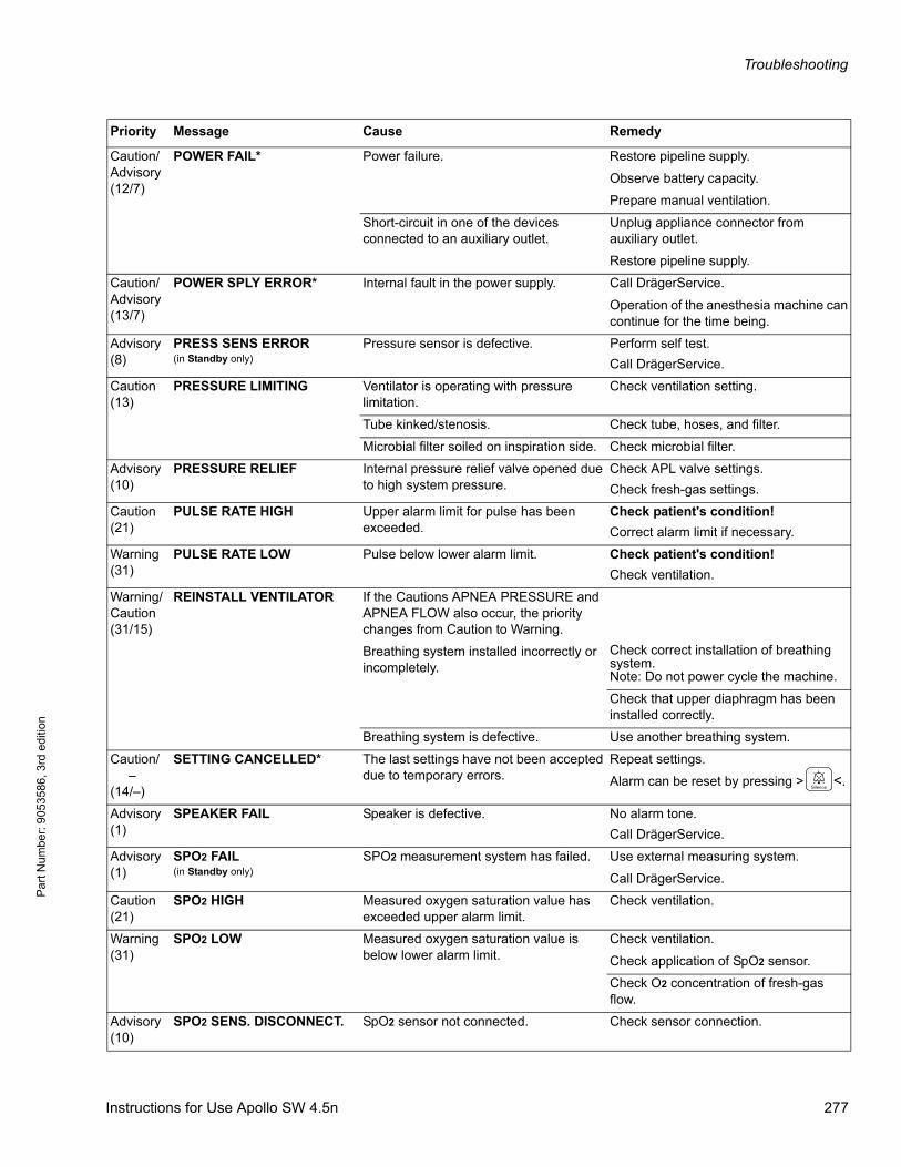
Troubleshooting
Par
t Num
ber:
905
3586
, 3rd
edi
tion
Caution/Advisory(12/7)
POWER FAIL* Power failure. Restore pipeline supply.
Observe battery capacity.
Prepare manual ventilation.
Short-circuit in one of the devices connected to an auxiliary outlet.
Unplug appliance connector from auxiliary outlet.
Restore pipeline supply.
Caution/Advisory(13/7)
POWER SPLY ERROR* Internal fault in the power supply. Call DrägerService.
Operation of the anesthesia machine can continue for the time being.
Advisory(8)
PRESS SENS ERROR(in Standby only)
Pressure sensor is defective. Perform self test.
Call DrägerService.
Caution(13)
PRESSURE LIMITING Ventilator is operating with pressure limitation.
Check ventilation setting.
Tube kinked/stenosis. Check tube, hoses, and filter.
Microbial filter soiled on inspiration side. Check microbial filter.
Advisory(10)
PRESSURE RELIEF Internal pressure relief valve opened due to high system pressure.
Check APL valve settings.
Check fresh-gas settings.
Caution(21)
PULSE RATE HIGH Upper alarm limit for pulse has been exceeded.
Check patient's condition!
Correct alarm limit if necessary.
Warning(31)
PULSE RATE LOW Pulse below lower alarm limit. Check patient's condition!
Check ventilation.
Warning/Caution(31/15)
REINSTALL VENTILATOR If the Cautions APNEA PRESSURE and APNEA FLOW also occur, the priority changes from Caution to Warning.
Breathing system installed incorrectly or incompletely.
Check correct installation of breathing system.Note: Do not power cycle the machine.
Check that upper diaphragm has been installed correctly.
Breathing system is defective. Use another breathing system.
Caution/ –(14/–)
SETTING CANCELLED* The last settings have not been accepted due to temporary errors.
Repeat settings.
Alarm can be reset by pressing > <.
Advisory(1)
SPEAKER FAIL Speaker is defective. No alarm tone.
Call DrägerService.
Advisory(1)
SPO2 FAIL(in Standby only)
SPO2 measurement system has failed. Use external measuring system.
Call DrägerService.
Caution(21)
SPO2 HIGH Measured oxygen saturation value has exceeded upper alarm limit.
Check ventilation.
Warning(31)
SPO2 LOW Measured oxygen saturation value is below lower alarm limit.
Check ventilation.
Check application of SpO2 sensor.
Check O2 concentration of fresh-gas flow.
Advisory(10)
SPO2 SENS. DISCONNECT. SpO2 sensor not connected. Check sensor connection.
Priority Message Cause Remedy
Instructions for Use Apollo SW 4.5n 277
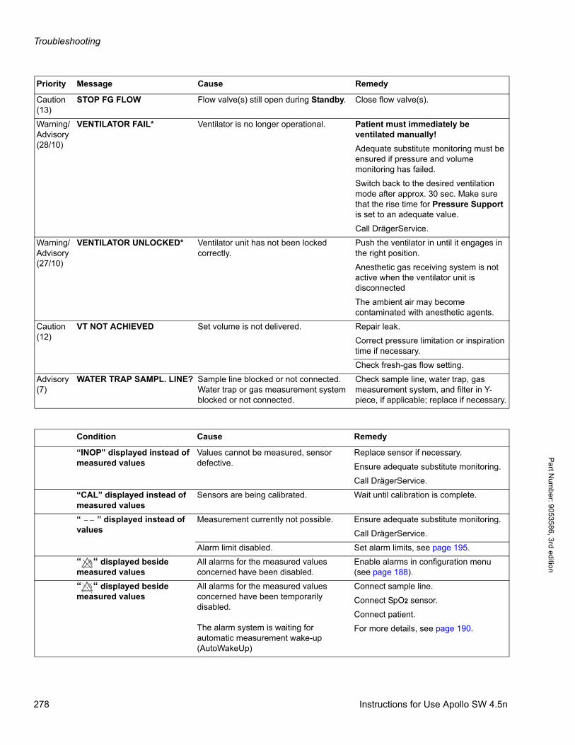
Troubleshooting
Pa
rt Num
ber: 905358
6, 3rd edition
Caution(13)
STOP FG FLOW Flow valve(s) still open during Standby. Close flow valve(s).
Warning/Advisory(28/10)
VENTILATOR FAIL* Ventilator is no longer operational. Patient must immediately be ventilated manually!
Adequate substitute monitoring must be ensured if pressure and volume monitoring has failed.
Switch back to the desired ventilation mode after approx. 30 sec. Make sure that the rise time for Pressure Support is set to an adequate value.
Call DrägerService.
Warning/Advisory(27/10)
VENTILATOR UNLOCKED* Ventilator unit has not been locked correctly.
Push the ventilator in until it engages in the right position.
Anesthetic gas receiving system is not active when the ventilator unit is disconnected
The ambient air may become contaminated with anesthetic agents.
Caution(12)
VT NOT ACHIEVED Set volume is not delivered. Repair leak.
Correct pressure limitation or inspiration time if necessary.
Check fresh-gas flow setting.
Advisory(7)
WATER TRAP SAMPL. LINE? Sample line blocked or not connected. Water trap or gas measurement system blocked or not connected.
Check sample line, water trap, gas measurement system, and filter in Y-piece, if applicable; replace if necessary.
Priority Message Cause Remedy
Condition Cause Remedy
“INOP” displayed instead of measured values
Values cannot be measured, sensor defective.
Replace sensor if necessary.
Ensure adequate substitute monitoring.
Call DrägerService.
“CAL” displayed instead of measured values
Sensors are being calibrated. Wait until calibration is complete.
“ ” displayed instead of values
Measurement currently not possible. Ensure adequate substitute monitoring.
Call DrägerService.
Alarm limit disabled. Set alarm limits, see page 195.
“ “ displayed beside measured values
All alarms for the measured values concerned have been disabled.
Enable alarms in configuration menu (see page 188).
“ “ displayed beside measured values
All alarms for the measured values concerned have been temporarily disabled.
The alarm system is waiting for automatic measurement wake-up (AutoWakeUp)
Connect sample line.
Connect SpO2 sensor.
Connect patient.
For more details, see page 190.
278 Instructions for Use Apollo SW 4.5n
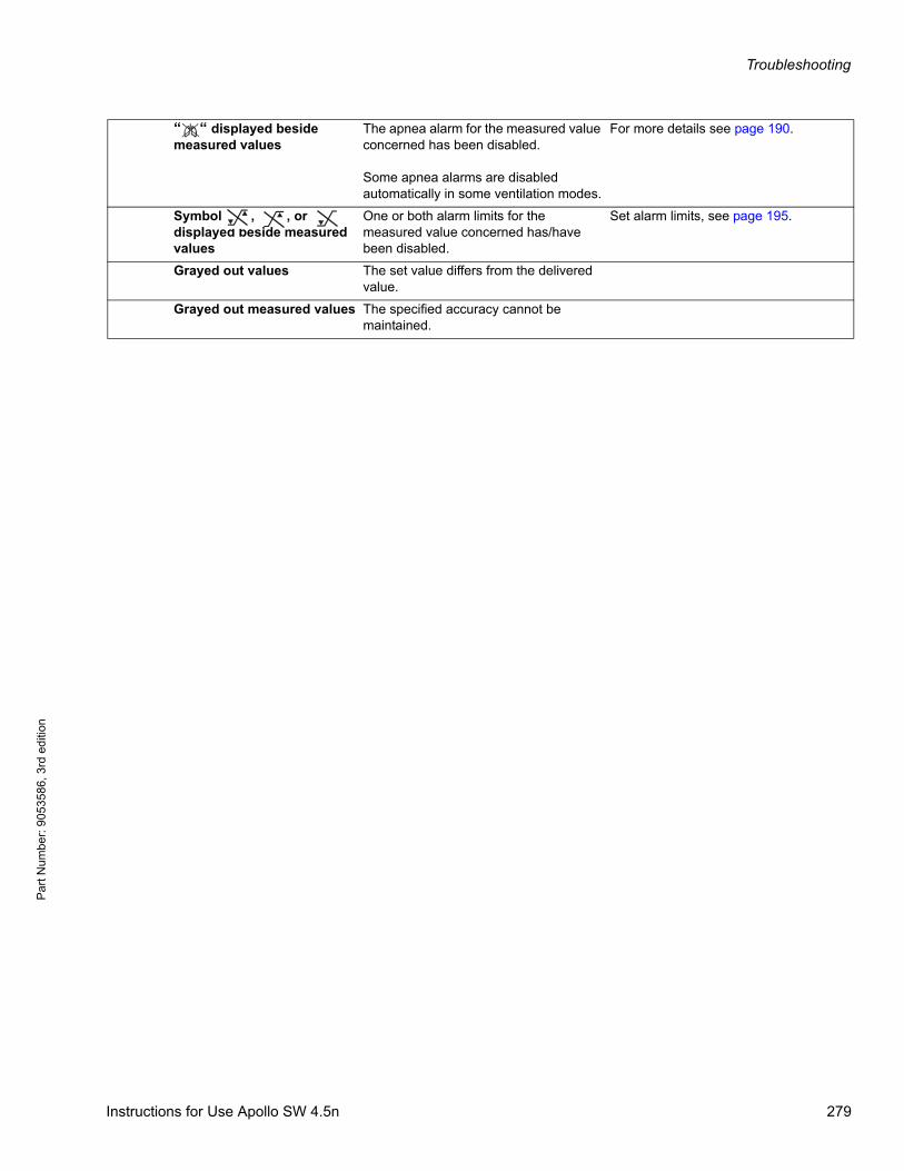
Troubleshooting
Par
t Num
ber:
905
3586
, 3rd
edi
tion
“ “ displayed beside measured values
The apnea alarm for the measured value concerned has been disabled.
Some apnea alarms are disabled automatically in some ventilation modes.
For more details see page 190.
Symbol , , or displayed beside measured values
One or both alarm limits for the measured value concerned has/have been disabled.
Set alarm limits, see page 195.
Grayed out values The set value differs from the delivered value.
Grayed out measured values The specified accuracy cannot be maintained.
_ > <
Instructions for Use Apollo SW 4.5n 279

Troubleshooting
Pa
rt Num
ber: 905358
6, 3rd edition
This page intentionally left blank.
280 Instructions for Use Apollo SW 4.5n
Specifications
Par
t Num
ber:
905
3586
, 3rd
edi
tion
Specifications
ContentsSpecifications . . . . . . . . . . . . . . . . . . . . . . . . . . . . . . . . . . . . . . . . . . . . . . . . . . . . . . . . . . . . . . . . . . . . . . . . . . 283
Ambient conditions . . . . . . . . . . . . . . . . . . . . . . . . . . . . . . . . . . . . . . . . . . . . . . . . . . . . . . . . . . . . . . . . . . . . . . . 283
Dimensions . . . . . . . . . . . . . . . . . . . . . . . . . . . . . . . . . . . . . . . . . . . . . . . . . . . . . . . . . . . . . . . . . . . . . . . . . . . . . 284
Weight . . . . . . . . . . . . . . . . . . . . . . . . . . . . . . . . . . . . . . . . . . . . . . . . . . . . . . . . . . . . . . . . . . . . . . . . . . . . . . . . 284
Monitor screen . . . . . . . . . . . . . . . . . . . . . . . . . . . . . . . . . . . . . . . . . . . . . . . . . . . . . . . . . . . . . . . . . . . . . . . . . . 284
Life span . . . . . . . . . . . . . . . . . . . . . . . . . . . . . . . . . . . . . . . . . . . . . . . . . . . . . . . . . . . . . . . . . . . . . . . . . . . . . . . 284
Operating data . . . . . . . . . . . . . . . . . . . . . . . . . . . . . . . . . . . . . . . . . . . . . . . . . . . . . . . . . . . . . . . . . . . . . . . . . . 285
Protection class . . . . . . . . . . . . . . . . . . . . . . . . . . . . . . . . . . . . . . . . . . . . . . . . . . . . . . . . . . . . . . . . . . . . . . . . . 286
Electromagnetic compatibility (EMC) . . . . . . . . . . . . . . . . . . . . . . . . . . . . . . . . . . . . . . . . . . . . . . . . . . . . . . . . . 287
Classification . . . . . . . . . . . . . . . . . . . . . . . . . . . . . . . . . . . . . . . . . . . . . . . . . . . . . . . . . . . . . . . . . . . . . . . . . . . 287
UMDNS Code . . . . . . . . . . . . . . . . . . . . . . . . . . . . . . . . . . . . . . . . . . . . . . . . . . . . . . . . . . . . . . . . . . . . . . . . . . . 287
GMDN code . . . . . . . . . . . . . . . . . . . . . . . . . . . . . . . . . . . . . . . . . . . . . . . . . . . . . . . . . . . . . . . . . . . . . . . . . . . . 287
Fresh-gas delivery . . . . . . . . . . . . . . . . . . . . . . . . . . . . . . . . . . . . . . . . . . . . . . . . . . . . . . . . . . . . . . . . . . . . . . . 287
Auxiliary O2 flow meter . . . . . . . . . . . . . . . . . . . . . . . . . . . . . . . . . . . . . . . . . . . . . . . . . . . . . . . . . . . . . . . . . . . . 288
Breathing system . . . . . . . . . . . . . . . . . . . . . . . . . . . . . . . . . . . . . . . . . . . . . . . . . . . . . . . . . . . . . . . . . . . . . . . . 288
Auxiliary common gas outlet (CGO) (Optional) . . . . . . . . . . . . . . . . . . . . . . . . . . . . . . . . . . . . . . . . . . . . . . . . . 290
Ventilator . . . . . . . . . . . . . . . . . . . . . . . . . . . . . . . . . . . . . . . . . . . . . . . . . . . . . . . . . . . . . . . . . . . . . . . . . . . . . . . 291
Measuring systems . . . . . . . . . . . . . . . . . . . . . . . . . . . . . . . . . . . . . . . . . . . . . . . . . . . . . . . . . . . . . . . . . . . . . . . 292
Frequency measurement . . . . . . . . . . . . . . . . . . . . . . . . . . . . . . . . . . . . . . . . . . . . . . . . . . . . . . . . . . . . . . . . . . 295
Gas measurement . . . . . . . . . . . . . . . . . . . . . . . . . . . . . . . . . . . . . . . . . . . . . . . . . . . . . . . . . . . . . . . . . . . . . . . 296
Interfaces . . . . . . . . . . . . . . . . . . . . . . . . . . . . . . . . . . . . . . . . . . . . . . . . . . . . . . . . . . . . . . . . . . . . . . . . . . . . . . 300
Latex use . . . . . . . . . . . . . . . . . . . . . . . . . . . . . . . . . . . . . . . . . . . . . . . . . . . . . . . . . . . . . . . . . . . . . . . . . . . . . . 301
Schematic diagram of alarm tones . . . . . . . . . . . . . . . . . . . . . . . . . . . . . . . . . . . . . . . . . . . . . . . . . . . . . . . . . 302
EMC declaration . . . . . . . . . . . . . . . . . . . . . . . . . . . . . . . . . . . . . . . . . . . . . . . . . . . . . . . . . . . . . . . . . . . . . . . . 303
General information . . . . . . . . . . . . . . . . . . . . . . . . . . . . . . . . . . . . . . . . . . . . . . . . . . . . . . . . . . . . . . . . . . . . . . 303
Electromagnetic emissions . . . . . . . . . . . . . . . . . . . . . . . . . . . . . . . . . . . . . . . . . . . . . . . . . . . . . . . . . . . . . . . . . 303
Electromagnetic immunity . . . . . . . . . . . . . . . . . . . . . . . . . . . . . . . . . . . . . . . . . . . . . . . . . . . . . . . . . . . . . . . . . 304
Recommended separation distances to portable and mobile radio frequency communication devices . . . . . . . 305
Device combinations . . . . . . . . . . . . . . . . . . . . . . . . . . . . . . . . . . . . . . . . . . . . . . . . . . . . . . . . . . . . . . . . . . . . 306
Connections to IT-networks . . . . . . . . . . . . . . . . . . . . . . . . . . . . . . . . . . . . . . . . . . . . . . . . . . . . . . . . . . . . . . 306
Relevant standards . . . . . . . . . . . . . . . . . . . . . . . . . . . . . . . . . . . . . . . . . . . . . . . . . . . . . . . . . . . . . . . . . . . . . . 308
Instructions for Use Apollo SW 4.5n 281

Specifications
Pa
rt Num
ber: 905358
6, 3rd edition
This page intentionally left blank.
282 Instructions for Use Apollo SW 4.5n
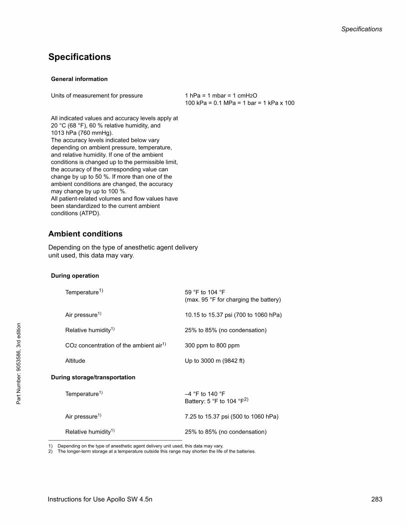
Specifications
Par
t Num
ber:
905
3586
, 3rd
edi
tion
Specifications
Ambient conditions
Depending on the type of anesthetic agent delivery unit used, this data may vary.
General information
Units of measurement for pressure 1 hPa = 1 mbar = 1 cmH2O100 kPa = 0.1 MPa = 1 bar = 1 kPa x 100
All indicated values and accuracy levels apply at 20 °C (68 °F), 60 % relative humidity, and 1013 hPa (760 mmHg).The accuracy levels indicated below vary depending on ambient pressure, temperature, and relative humidity. If one of the ambient conditions is changed up to the permissible limit, the accuracy of the corresponding value can change by up to 50 %. If more than one of the ambient conditions are changed, the accuracy may change by up to 100 %.All patient-related volumes and flow values have been standardized to the current ambient conditions (ATPD).
During operation
Temperature1) 59 °F to 104 °F(max. 95 °F for charging the battery)
Air pressure1) 10.15 to 15.37 psi (700 to 1060 hPa)
Relative humidity1) 25% to 85% (no condensation)
CO2 concentration of the ambient air1) 300 ppm to 800 ppm
Altitude Up to 3000 m (9842 ft)
During storage/transportation
Temperature1) –4 °F to 140 °FBattery: 5 °F to 104 °F2)
Air pressure1) 7.25 to 15.37 psi (500 to 1060 hPa)
Relative humidity1) 25% to 85% (no condensation)
1) Depending on the type of anesthetic agent delivery unit used, this data may vary.2) The longer-term storage at a temperature outside this range may shorten the life of the batteries.
Instructions for Use Apollo SW 4.5n 283

Specifications
Pa
rt Num
ber: 905358
6, 3rd edition
Dimensions(Variations may occur depending on the configuration)
Weight
Monitor screen
Flat screen, color, TFT, 12.1” diagonal,800 x 600 pixels
Life span
10 years
Machine dimensions (W x H x D) approx. 31.5 x 59.1 x 31.5 in. (85 x 150 x 80 cm)
Top shelf dimensions (W x D) approx. 24 x 20.9 in. (61 x 53 cm)
Writing surface (W x D) approx. 13 x 18 in. (33 x 46 cm)
Breathing system dimensions (W x H x D) approx. 14.8 x 15.9 x 13.6 in. (37.5 x 40.5 x 34.5 cm)
Nominal configurationconsisting of basic device, plug-in connector for 2 vaporizers, breathing system, CLIC adapter and CLIC absorber, breathing hoses, central supply hoses (5 m (16.4 ft)), scavenging hose (5 m (16.4 ft))
approx. 309 lbs (140 kg)
Various attached parts (e.g., baskets, flexible breathing bag holder, park holder for vaporizer, cylinder pressure reducers, gas cylinder holder, halogen light)
approx. 22 lbs (10 kg)
Writing table XXL + approx. 7 lbs (3 kg)
Endotracheal aspiration system with swivel arm and accessories
+ approx. 13 lbs (6 kg)
Swivel cupboard + approx. 29 lbs (13 kg)
Oval pole swivel arm + approx. 9 lbs (4 kg)
Pump mount + approx. 13 lbs (6 kg)
Permitted total weight 662 lbs (300 kg)
Breathing system without soda lime 9.7 lbs (4.4 kg)
284 Instructions for Use Apollo SW 4.5n
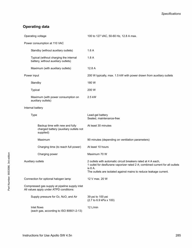
Specifications
Par
t Num
ber:
905
3586
, 3rd
edi
tion
Operating data
Operating voltage 100 to 127 VAC, 50-60 Hz, 12.8 A max.
Power consumption at 110 VAC
Standby (without auxiliary outlets) 1.6 A
Typical (without charging the internal battery, without auxiliary outlets)
1.8 A
Maximum (with auxiliary outlets) 12.8 A
Power input 200 W typically, max. 1.5 kW with power drawn from auxiliary outlets
Standby 180 W
Typical 200 W
Maximum (with power consumption on auxiliary outlets)
2.5 kW
Internal battery
Type Lead-gel batterySealed, maintenance-free
Backup time with new and fully charged battery (auxiliary outlets not supplied)
At least 30 minutes
Maximum 90 minutes (depending on ventilation parameters)
Charging time (to reach full power) At least 10 hours
Charging power Maximum 70 W
Auxiliary outlets 2 outlets with automatic circuit breakers rated at 4 A each,1 outlet for desflurane vaporizer rated 2 A; combined current for all outlets is 6 A.The outlets are isolated against mains to reduce leakage current.
Connection for optional halogen lamp 12 V max. 20 W
Compressed gas supply at pipeline supply inletAll values apply under ATPD conditions:
Supply pressure for O2, N2O, and Air 39 psi to 100 psi (2.7 to 6.9 kPa x 100)
Inlet flows(each gas, according to ISO 80601-2-13)
12 L/min
Instructions for Use Apollo SW 4.5n 285
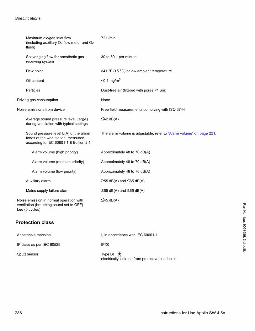
Specifications
Pa
rt Num
ber: 905358
6, 3rd edition
Protection class
Maximum oxygen inlet flow(including auxiliary O2 flow meter and O2 flush)
72 L/min
Scavenging flow for anesthetic gas receiving system
30 to 50 L per minute
Dew point >41 °F (>5 °C) below ambient temperature
Oil content <0.1 mg/m3
Particles Dust-free air (filtered with pores <1 µm)
Driving gas consumption None
Noise emissions from device Free field measurements complying with ISO 3744
Average sound pressure level Leq(A) during ventilation with typical settings
≤42 dB(A)
Sound pressure level L(A) of the alarm tones at the workstation, measured according to IEC 60601-1-8 Edition 2.1:
The alarm volume is adjustable, refer to “Alarm volume” on page 221.
Alarm volume (high priority) Approximately 48 to 70 dB(A)
Alarm volume (medium priority) Approximately 48 to 70 dB(A)
Alarm volume (low priority) Approximately 48 to 70 dB(A)
Auxiliary alarm ≥55 dB(A) and ≤65 dB(A)
Mains supply failure alarm ≥55 dB(A) and ≤65 dB(A)
Noise emission in normal operation with ventilation (breathing sound set to OFF)Leq (5 cycles)
≤45 dB(A)
Anesthesia machine I, in accordance with IEC 60601-1
IP class as per IEC 60529 IPX0
SpO2 sensor Type BF electrically isolated from protective conductor
286 Instructions for Use Apollo SW 4.5n
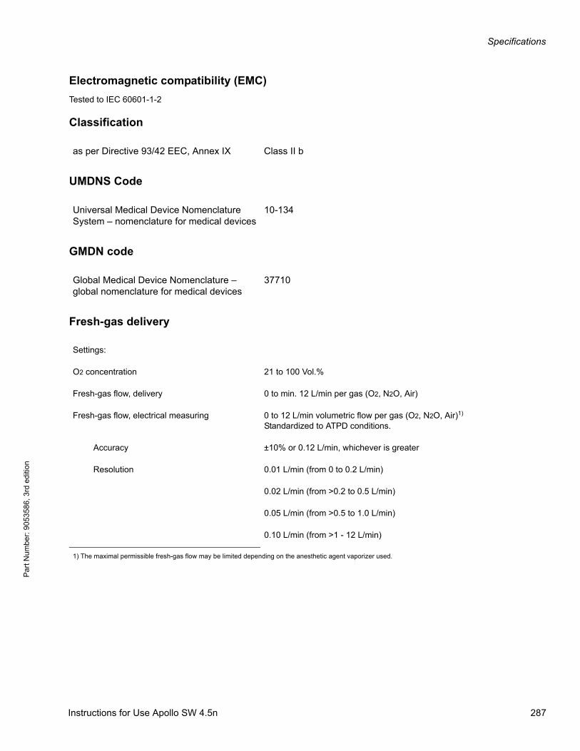
Specifications
Par
t Num
ber:
905
3586
, 3rd
edi
tion
Electromagnetic compatibility (EMC)
Tested to IEC 60601-1-2
Classification
UMDNS Code
GMDN code
Fresh-gas delivery
as per Directive 93/42 EEC, Annex IX Class II b
Universal Medical Device Nomenclature System – nomenclature for medical devices
10-134
Global Medical Device Nomenclature – global nomenclature for medical devices
37710
Settings:
O2 concentration 21 to 100 Vol.%
Fresh-gas flow, delivery 0 to min. 12 L/min per gas (O2, N2O, Air)
Fresh-gas flow, electrical measuring 0 to 12 L/min volumetric flow per gas (O2, N2O, Air)1)
Standardized to ATPD conditions.
Accuracy ±10% or 0.12 L/min, whichever is greater
Resolution 0.01 L/min (from 0 to 0.2 L/min)
0.02 L/min (from >0.2 to 0.5 L/min)
0.05 L/min (from >0.5 to 1.0 L/min)
0.10 L/min (from >1 - 12 L/min)
1) The maximal permissible fresh-gas flow may be limited depending on the anesthetic agent vaporizer used.
Instructions for Use Apollo SW 4.5n 287
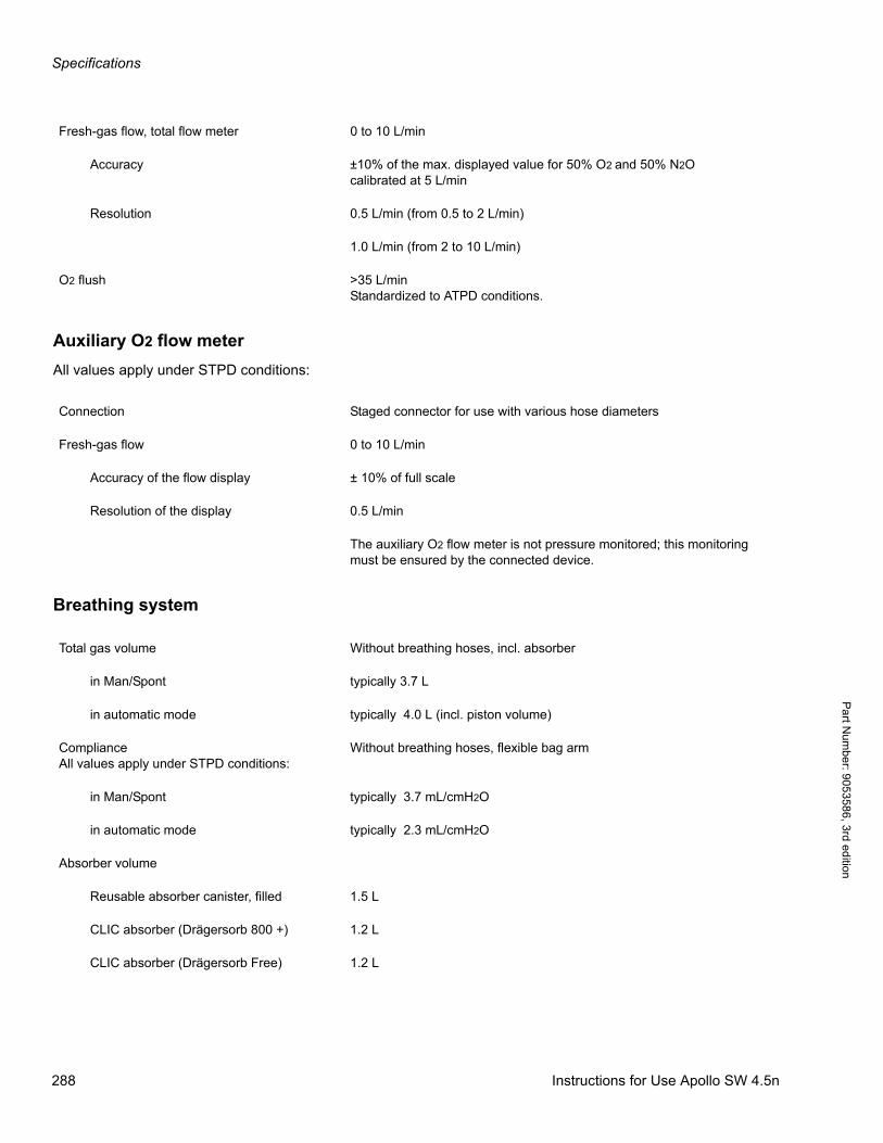
Specifications
Pa
rt Num
ber: 905358
6, 3rd edition
Auxiliary O2 flow meter
All values apply under STPD conditions:
Breathing system
Fresh-gas flow, total flow meter 0 to 10 L/min
Accuracy ±10% of the max. displayed value for 50% O2 and 50% N2Ocalibrated at 5 L/min
Resolution 0.5 L/min (from 0.5 to 2 L/min)
1.0 L/min (from 2 to 10 L/min)
O2 flush >35 L/minStandardized to ATPD conditions.
Connection Staged connector for use with various hose diameters
Fresh-gas flow 0 to 10 L/min
Accuracy of the flow display ± 10% of full scale
Resolution of the display 0.5 L/min
The auxiliary O2 flow meter is not pressure monitored; this monitoring must be ensured by the connected device.
Total gas volume Without breathing hoses, incl. absorber
in Man/Spont typically 3.7 L
in automatic mode typically 4.0 L (incl. piston volume)
ComplianceAll values apply under STPD conditions:
Without breathing hoses, flexible bag arm
in Man/Spont typically 3.7 mL/cmH2O
in automatic mode typically 2.3 mL/cmH2O
Absorber volume
Reusable absorber canister, filled 1.5 L
CLIC absorber (Drägersorb 800 +) 1.2 L
CLIC absorber (Drägersorb Free) 1.2 L
288 Instructions for Use Apollo SW 4.5n
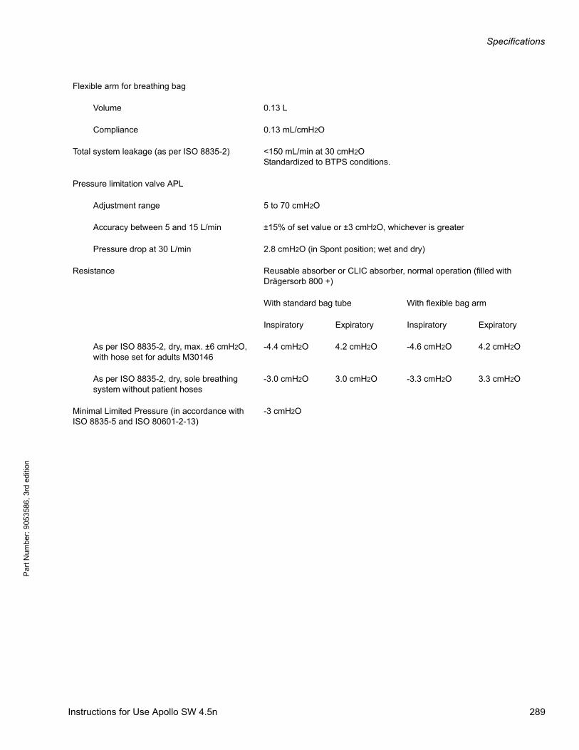
Specifications
Par
t Num
ber:
905
3586
, 3rd
edi
tion
Flexible arm for breathing bag
Volume 0.13 L
Compliance 0.13 mL/cmH2O
Total system leakage (as per ISO 8835-2) <150 mL/min at 30 cmH2OStandardized to BTPS conditions.
Pressure limitation valve APL
Adjustment range 5 to 70 cmH2O
Accuracy between 5 and 15 L/min ±15% of set value or ±3 cmH2O, whichever is greater
Pressure drop at 30 L/min 2.8 cmH2O (in Spont position; wet and dry)
Resistance Reusable absorber or CLIC absorber, normal operation (filled with Drägersorb 800 +)
With standard bag tube With flexible bag arm
Inspiratory Expiratory Inspiratory Expiratory
As per ISO 8835-2, dry, max. ±6 cmH2O, with hose set for adults M30146
-4.4 cmH2O 4.2 cmH2O -4.6 cmH2O 4.2 cmH2O
As per ISO 8835-2, dry, sole breathing system without patient hoses
-3.0 cmH2O 3.0 cmH2O -3.3 cmH2O 3.3 cmH2O
Minimal Limited Pressure (in accordance with ISO 8835-5 and ISO 80601-2-13)
-3 cmH2O
Instructions for Use Apollo SW 4.5n 289
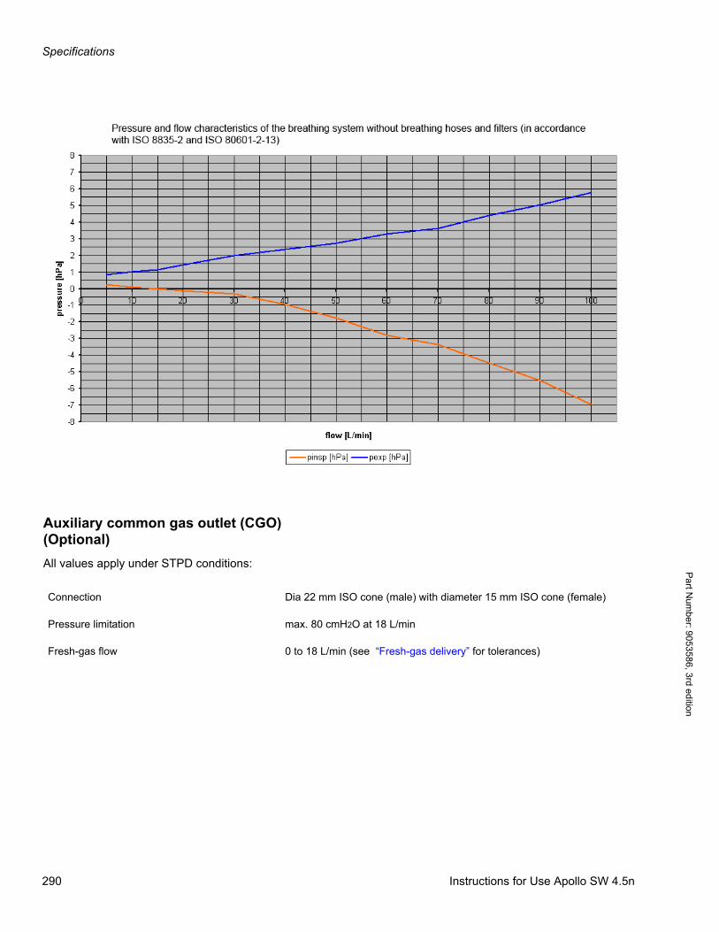
Specifications
Pa
rt Num
ber: 905358
6, 3rd edition
Auxiliary common gas outlet (CGO) (Optional)
All values apply under STPD conditions:
Connection Dia 22 mm ISO cone (male) with diameter 15 mm ISO cone (female)
Pressure limitation max. 80 cmH2O at 18 L/min
Fresh-gas flow 0 to 18 L/min (see “Fresh-gas delivery” for tolerances)
290 Instructions for Use Apollo SW 4.5n
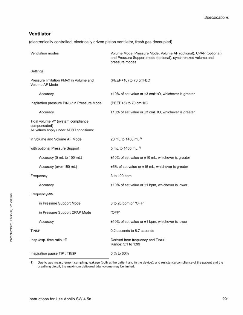
Specifications
Par
t Num
ber:
905
3586
, 3rd
edi
tion
Ventilator
(electronically controlled, electrically driven piston ventilator, fresh gas decoupled)
Ventilation modes Volume Mode, Pressure Mode, Volume AF (optional), CPAP (optional), and Pressure Support mode (optional), synchronized volume and pressure modes
Settings:
Pressure limitation PMAX in Volume and Volume AF Mode
(PEEP+10) to 70 cmH2O
Accuracy ±10% of set value or ±3 cmH2O, whichever is greater
Inspiration pressure PINSP in Pressure Mode (PEEP+5) to 70 cmH2O
Accuracy ±10% of set value or ±3 cmH2O, whichever is greater
Tidal volume VT (system compliance compensated) All values apply under ATPD conditions:
in Volume and Volume AF Mode 20 mL to 1400 mL1)
with optional Pressure Support 5 mL to 1400 mL 1)
Accuracy (5 mL to 150 mL) ±10% of set value or ±10 mL, whichever is greater
Accuracy (over 150 mL) ±5% of set value or ±15 mL, whichever is greater
Frequency 3 to 100 bpm
Accuracy ±10% of set value or ±1 bpm, whichever is lower
FrequencyMIN
in Pressure Support Mode 3 to 20 bpm or “OFF”
in Pressure Support CPAP Mode “OFF”
Accuracy ±10% of set value or ±1 bpm, whichever is lower
TINSP 0.2 seconds to 6.7 seconds
Insp./exp. time ratio I:E Derived from frequency and TINSPRange: 5:1 to 1:99
Inspiration pause TIP : TINSP 0 % to 60%
1) Due to gas measurement sampling, leakage (both at the patient and in the device), and resistance/compliance of the patient and the breathing circuit, the maximum delivered tidal volume may be limited.
Instructions for Use Apollo SW 4.5n 291
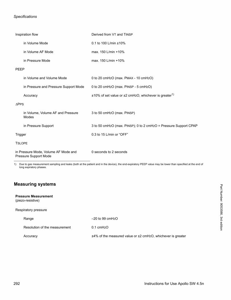
Specifications
Pa
rt Num
ber: 905358
6, 3rd edition
Measuring systems
Inspiration flow Derived from VT and TINSP
in Volume Mode 0.1 to 100 L/min ±10%
in Volume AF Mode max. 150 L/min +10%
in Pressure Mode max. 150 L/min +10%
PEEP
in Volume and Volume Mode 0 to 20 cmH2O (max. PMAX - 10 cmH2O)
in Pressure and Pressure Support Mode 0 to 20 cmH2O (max. PINSP - 5 cmH2O)
Accuracy ±10% of set value or ±2 cmH2O, whichever is greater1)
ΔPPS
in Volume, Volume AF and Pressure Modes
3 to 50 cmH2O (max. PINSP)
in Pressure Support 3 to 50 cmH2O (max. PINSP); 0 to 2 cmH2O = Pressure Support CPAP
Trigger 0.3 to 15 L/min or “OFF”
TSLOPE
in Pressure Mode, Volume AF Mode and Pressure Support Mode
0 seconds to 2 seconds
1) Due to gas measurement sampling and leaks (both at the patient and in the device), the end-expiratory PEEP value may be lower than specified at the end of long expiratory phases.
Pressure Measurement(piezo-resistive)
Respiratory pressure
Range –20 to 99 cmH2O
Resolution of the measurement 0.1 cmH2O
Accuracy ±4% of the measured value or ±2 cmH2O, whichever is greater
292 Instructions for Use Apollo SW 4.5n
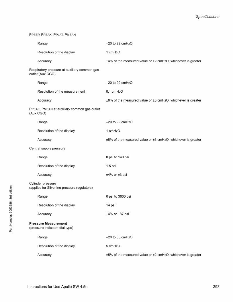
Specifications
Par
t Num
ber:
905
3586
, 3rd
edi
tion
PPEEP, PPEAK, PPLAT, PMEAN
Range –20 to 99 cmH2O
Resolution of the display 1 cmH2O
Accuracy ±4% of the measured value or ±2 cmH2O, whichever is greater
Respiratory pressure at auxiliary common gas outlet (Aux CGO)
Range –20 to 99 cmH2O
Resolution of the measurement 0.1 cmH2O
Accuracy ±8% of the measured value or ±3 cmH2O, whichever is greater
PPEAK, PMEAN at auxiliary common gas outlet (Aux CGO)
Range –20 to 99 cmH2O
Resolution of the display 1 cmH2O
Accuracy ±8% of the measured value or ±3 cmH2O, whichever is greater
Central supply pressure
Range 0 psi to 140 psi
Resolution of the display 1.5 psi
Accuracy ±4% or ±3 psi
Cylinder pressure(applies for Silverline pressure regulators)
Range 0 psi to 3600 psi
Resolution of the display 14 psi
Accuracy ±4% or ±87 psi
Pressure Measurement(pressure indicator, dial type)
Range –20 to 80 cmH2O
Resolution of the display 5 cmH2O
Accuracy ±5% of the measured value or ±2 cmH2O, whichever is greater
Instructions for Use Apollo SW 4.5n 293

Specifications
Pa
rt Num
ber: 905358
6, 3rd edition
Flow measurement(hot wire anemometry)All values apply under ATPD conditions:
Flow
Range –180 to 180 L/min
Resolution of the measurement 0.1 L/min
Accuracy at 60 L/min ±8% of measured value
Tidal volume VT
Range 0 mL to 9999 mL
Resolution of the display 1 mL
Accuracy ±8% of the measured value or ±5 mL, whichever is greater
Delta VT
Range 0 mL to 9999 mL
Resolution of the display 1 mL
Accuracy ±16% or ±10 mL, whichever is greater
Volume VTINSP
Range 0 mL to 9999 mL
Resolution of the display 1 mL
Accuracy ±8% of the measured value or ±5 mL, whichever is greater
Minute volume MV
Range 0 to 99.9 L/min
Resolution of the display 0.1 L/min
Accuracy ±8% of the measured value or ±0.1 L/min, whichever is greater
Compliance CPAT
Range 0 to 250 mL/cmH2O
Resolution of the display 0.1 mL/cmH2O
Accuracy ±15% of the measured value or ±0.5 mL/cmH2O, whichever is greater
294 Instructions for Use Apollo SW 4.5n
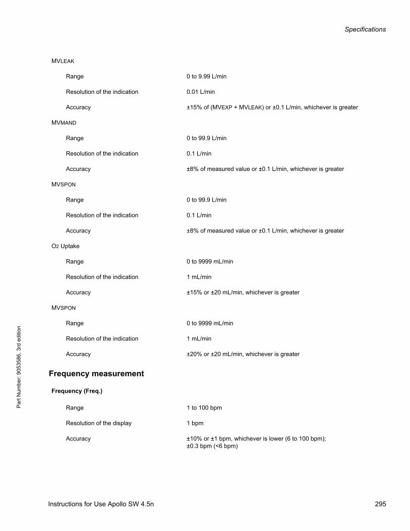
Specifications
Par
t Num
ber:
905
3586
, 3rd
edi
tion
Frequency measurement
MVLEAK
Range 0 to 9.99 L/min
Resolution of the indication 0.01 L/min
Accuracy ±15% of (MVEXP + MVLEAK) or ±0.1 L/min, whichever is greater
MVMAND
Range 0 to 99.9 L/min
Resolution of the indication 0.1 L/min
Accuracy ±8% of measured value or ±0.1 L/min, whichever is greater
MVSPON
Range 0 to 99.9 L/min
Resolution of the indication 0.1 L/min
Accuracy ±8% of measured value or ±0.1 L/min, whichever is greater
O2 Uptake
Range 0 to 9999 mL/min
Resolution of the indication 1 mL/min
Accuracy ±15% or ±20 mL/min, whichever is greater
MVSPON
Range 0 to 9999 mL/min
Resolution of the indication 1 mL/min
Accuracy ±20% or ±20 mL/min, whichever is greater
Frequency (Freq.)
Range 1 to 100 bpm
Resolution of the display 1 bpm
Accuracy ±10% or ±1 bpm, whichever is lower (6 to 100 bpm);±0.3 bpm (<6 bpm)
Instructions for Use Apollo SW 4.5n 295
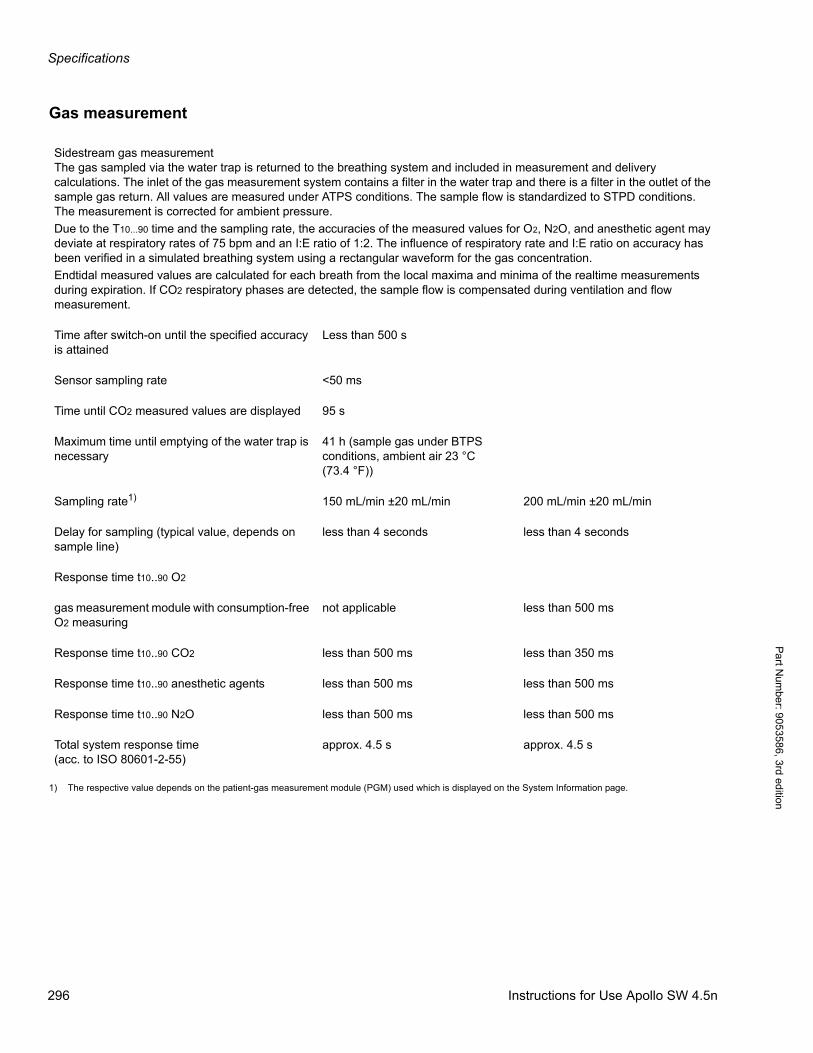
Specifications
Pa
rt Num
ber: 905358
6, 3rd edition
Gas measurement
Sidestream gas measurementThe gas sampled via the water trap is returned to the breathing system and included in measurement and delivery calculations. The inlet of the gas measurement system contains a filter in the water trap and there is a filter in the outlet of the sample gas return. All values are measured under ATPS conditions. The sample flow is standardized to STPD conditions.The measurement is corrected for ambient pressure.
Due to the T10...90 time and the sampling rate, the accuracies of the measured values for O2, N2O, and anesthetic agent may deviate at respiratory rates of 75 bpm and an I:E ratio of 1:2. The influence of respiratory rate and I:E ratio on accuracy has been verified in a simulated breathing system using a rectangular waveform for the gas concentration.
Endtidal measured values are calculated for each breath from the local maxima and minima of the realtime measurements during expiration. If CO2 respiratory phases are detected, the sample flow is compensated during ventilation and flow measurement.
Time after switch-on until the specified accuracy is attained
Less than 500 s
Sensor sampling rate <50 ms
Time until CO2 measured values are displayed 95 s
Maximum time until emptying of the water trap is necessary
41 h (sample gas under BTPS conditions, ambient air 23 °C (73.4 °F))
Sampling rate1) 150 mL/min ±20 mL/min 200 mL/min ±20 mL/min
Delay for sampling (typical value, depends on sample line)
less than 4 seconds less than 4 seconds
Response time t10..90 O2
gas measurement module with consumption-free O2 measuring
not applicable less than 500 ms
Response time t10..90 CO2 less than 500 ms less than 350 ms
Response time t10..90 anesthetic agents less than 500 ms less than 500 ms
Response time t10..90 N2O less than 500 ms less than 500 ms
Total system response time(acc. to ISO 80601-2-55)
approx. 4.5 s approx. 4.5 s
1) The respective value depends on the patient-gas measurement module (PGM) used which is displayed on the System Information page.
296 Instructions for Use Apollo SW 4.5n
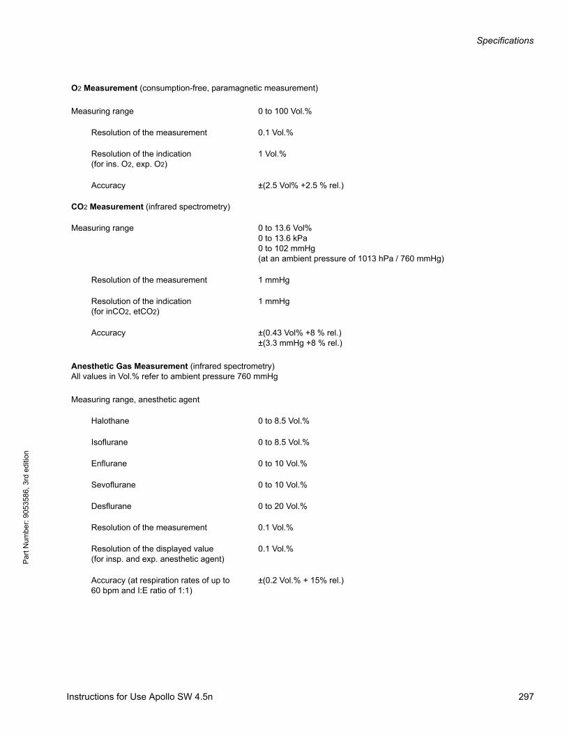
Specifications
Par
t Num
ber:
905
3586
, 3rd
edi
tion
O2 Measurement (consumption-free, paramagnetic measurement)
Measuring range 0 to 100 Vol.%
Resolution of the measurement 0.1 Vol.%
Resolution of the indication(for ins. O2, exp. O2)
1 Vol.%
Accuracy ±(2.5 Vol% +2.5 % rel.)
CO2 Measurement (infrared spectrometry)
Measuring range 0 to 13.6 Vol%0 to 13.6 kPa0 to 102 mmHg(at an ambient pressure of 1013 hPa / 760 mmHg)
Resolution of the measurement 1 mmHg
Resolution of the indication(for inCO2, etCO2)
1 mmHg
Accuracy ±(0.43 Vol% +8 % rel.)±(3.3 mmHg +8 % rel.)
Anesthetic Gas Measurement (infrared spectrometry)All values in Vol.% refer to ambient pressure 760 mmHg
Measuring range, anesthetic agent
Halothane 0 to 8.5 Vol.%
Isoflurane 0 to 8.5 Vol.%
Enflurane 0 to 10 Vol.%
Sevoflurane 0 to 10 Vol.%
Desflurane 0 to 20 Vol.%
Resolution of the measurement 0.1 Vol.%
Resolution of the displayed value(for insp. and exp. anesthetic agent)
0.1 Vol.%
Accuracy (at respiration rates of up to60 bpm and I:E ratio of 1:1)
±(0.2 Vol.% + 15% rel.)
Instructions for Use Apollo SW 4.5n 297
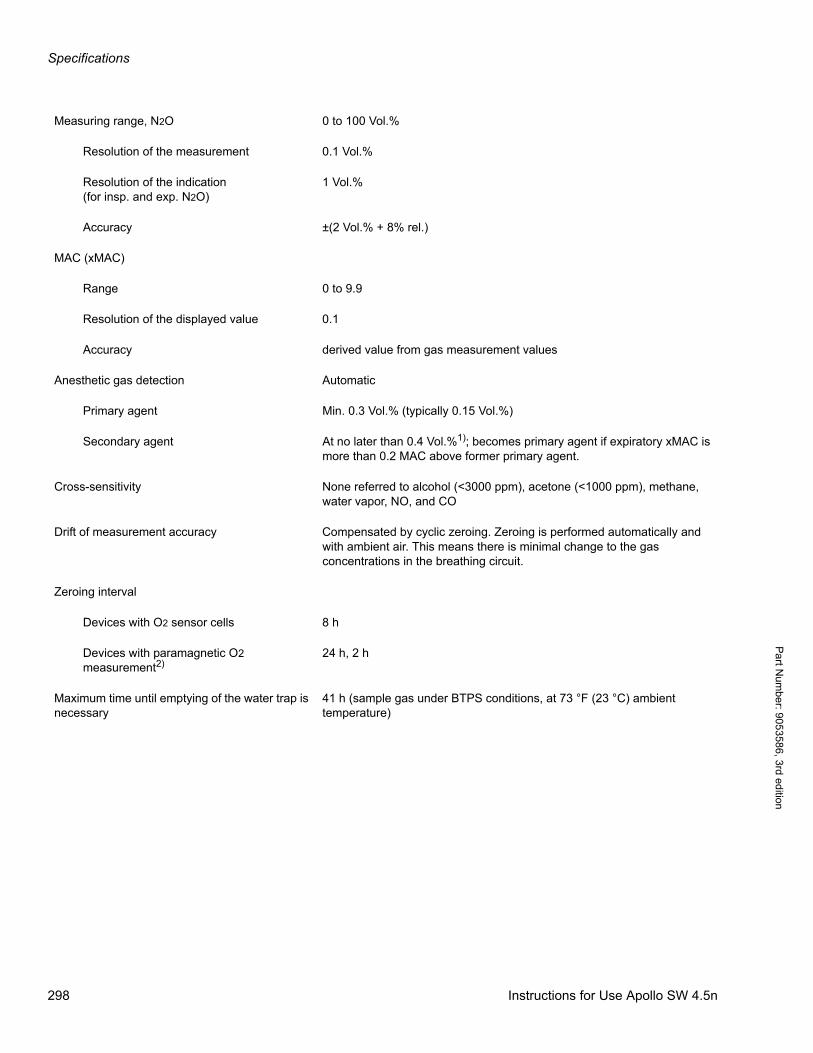
Specifications
Pa
rt Num
ber: 905358
6, 3rd edition
Measuring range, N2O 0 to 100 Vol.%
Resolution of the measurement 0.1 Vol.%
Resolution of the indication(for insp. and exp. N2O)
1 Vol.%
Accuracy ±(2 Vol.% + 8% rel.)
MAC (xMAC)
Range 0 to 9.9
Resolution of the displayed value 0.1
Accuracy derived value from gas measurement values
Anesthetic gas detection Automatic
Primary agent Min. 0.3 Vol.% (typically 0.15 Vol.%)
Secondary agent At no later than 0.4 Vol.%1); becomes primary agent if expiratory xMAC is more than 0.2 MAC above former primary agent.
Cross-sensitivity None referred to alcohol (<3000 ppm), acetone (<1000 ppm), methane, water vapor, NO, and CO
Drift of measurement accuracy Compensated by cyclic zeroing. Zeroing is performed automatically and with ambient air. This means there is minimal change to the gas concentrations in the breathing circuit.
Zeroing interval
Devices with O2 sensor cells 8 h
Devices with paramagnetic O2 measurement2)
24 h, 2 h
Maximum time until emptying of the water trap is necessary
41 h (sample gas under BTPS conditions, at 73 °F (23 °C) ambient temperature)
298 Instructions for Use Apollo SW 4.5n
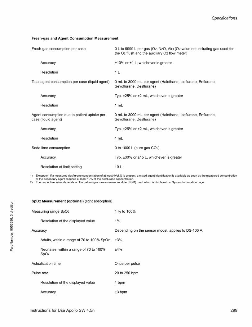
Specifications
Par
t Num
ber:
905
3586
, 3rd
edi
tion
Fresh-gas and Agent Consumption Measurement
Fresh-gas consumption per case 0 L to 9999 L per gas (O2, N2O, Air) (O2 value not including gas used for the O2 flush and the auxiliary O2 flow meter)
Accuracy ±10% or ±1 L, whichever is greater
Resolution 1 L
Total agent consumption per case (liquid agent) 0 mL to 3000 mL per agent (Halothane, Isoflurane, Enflurane, Sevoflurane, Desflurane)
Accuracy Typ. ±25% or ±2 mL, whichever is greater
Resolution 1 mL
Agent consumption due to patient uptake per case (liquid agent)
0 mL to 3000 mL per agent (Halothane, Isoflurane, Enflurane, Sevoflurane, Desflurane)
Accuracy Typ. ±25% or ±2 mL, whichever is greater
Resolution 1 mL
Soda lime consumption 0 to 1000 L (pure gas CO2)
Accuracy Typ. ±30% or ±15 L, whichever is greater
Resolution of limit setting 10 L
1) Exception: If a measured desflurane concentration of at least 4Vol.% is present, a mixed agent identification is available as soon as the measured concentration of the secondary agent reaches at least 10% of the desflurane concentration.
2) The respective value depends on the patient-gas measurement module (PGM) used which is displayed on System Information page.
SpO2 Measurement (optional) (light absorption)
Measuring range SpO2 1 % to 100%
Resolution of the displayed value 1%
Accuracy Depending on the sensor model, applies to DS-100 A.
Adults, within a range of 70 to 100% SpO2 ±3%
Neonates, within a range of 70 to 100% SpO2
±4%
Actualization time Once per pulse
Pulse rate 20 to 250 bpm
Resolution of the displayed value 1 bpm
Accuracy ±3 bpm
Instructions for Use Apollo SW 4.5n 299
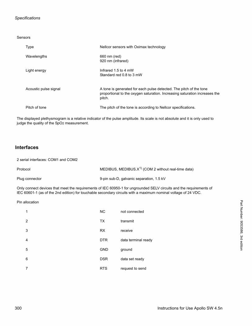
Specifications
Pa
rt Num
ber: 905358
6, 3rd edition
Interfaces
Sensors
Type Nellcor sensors with Oximax technology
Wavelengths 660 nm (red)920 nm (infrared)
Light energy Infrared 1.5 to 4 mWStandard red 0.8 to 3 mW
Acoustic pulse signal A tone is generated for each pulse detected. The pitch of the tone proportional to the oxygen saturation. Increasing saturation increases the pitch.
Pitch of tone The pitch of the tone is according to Nellcor specifications.
The displayed plethysmogram is a relative indicator of the pulse amplitude. Its scale is not absolute and it is only used to judge the quality of the SpO2 measurement.
2 serial interfaces: COM1 and COM2
Protocol MEDIBUS, MEDIBUS.X1) (COM 2 without real-time data)
Plug connector 9-pin sub-D, galvanic separation, 1.5 kV
Only connect devices that meet the requirements of IEC 60950-1 for ungrounded SELV circuits and the requirements of IEC 60601-1 (as of the 2nd edition) for touchable secondary circuits with a maximum nominal voltage of 24 VDC.
Pin allocation
1 NC not connected
2 TX transmit
3 RX receive
4 DTR data terminal ready
5 GND ground
6 DSR data set ready
7 RTS request to send
300 Instructions for Use Apollo SW 4.5n
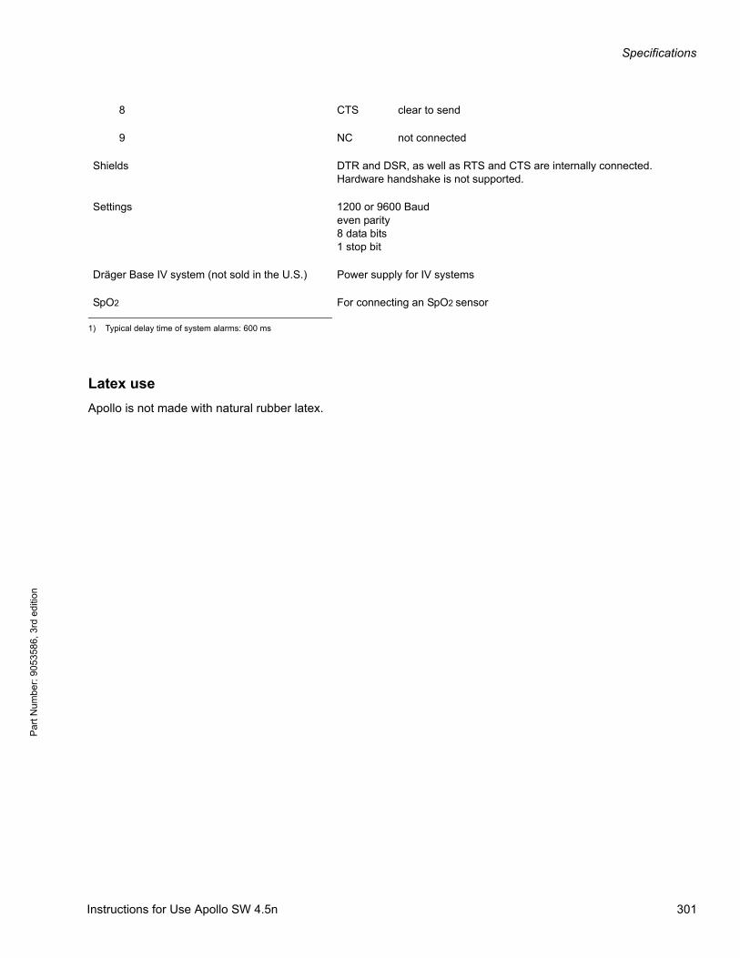
Specifications
Par
t Num
ber:
905
3586
, 3rd
edi
tion
Latex use
Apollo is not made with natural rubber latex.
8 CTS clear to send
9 NC not connected
Shields DTR and DSR, as well as RTS and CTS are internally connected. Hardware handshake is not supported.
Settings 1200 or 9600 Baudeven parity8 data bits1 stop bit
Dräger Base IV system (not sold in the U.S.) Power supply for IV systems
SpO2 For connecting an SpO2 sensor
1) Typical delay time of system alarms: 600 ms
Instructions for Use Apollo SW 4.5n 301
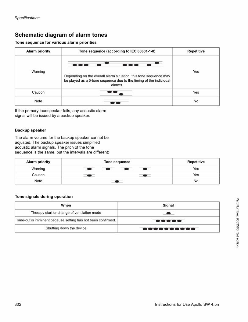
Specifications
Pa
rt Num
ber: 905358
6, 3rd edition
Schematic diagram of alarm tonesTone sequence for various alarm priorities
If the primary loudspeaker fails, any acoustic alarm signal will be issued by a backup speaker.
Backup speaker
The alarm volume for the backup speaker cannot be adjusted. The backup speaker issues simplified acoustic alarm signals. The pitch of the tone sequence is the same, but the intervals are different:
Tone signals during operation
Alarm priority Tone sequence (according to IEC 60601-1-8) Repetitive
WarningDepending on the overall alarm situation, this tone sequence may be played as a 5-tone sequence due to the timing of the individual
alarms.
Yes
Caution Yes
Note No
Alarm priority Tone sequence Repetitive
Warning Yes
Caution Yes
Note No
When Signal
Therapy start or change of ventilation mode
Time-out is imminent because setting has not been confirmed.
Shutting down the device
302 Instructions for Use Apollo SW 4.5n
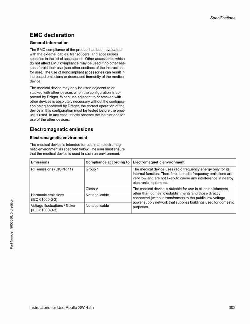
Specifications
Par
t Num
ber:
905
3586
, 3rd
edi
tion
EMC declarationGeneral information
The EMC compliance of the product has been evaluated with the external cables, transducers, and accessories specified in the list of accessories. Other accessories which do not affect EMC compliance may be used if no other rea-sons forbid their use (see other sections of the instructions for use). The use of noncompliant accessories can result in increased emissions or decreased immunity of the medical device.
The medical device may only be used adjacent to or stacked with other devices when the configuration is ap-proved by Dräger. When use adjacent to or stacked with other devices is absolutely necessary without the configura-tion being approved by Dräger, the correct operation of the device in this configuration must be tested before the prod-uct is used. In any case, strictly observe the instructions for use of the other devices.
Electromagnetic emissions
Electromagnetic environment
The medical device is intended for use in an electromag-netic environment as specified below. The user must ensure that the medical device is used in such an environment.
Emissions Compliance according to Electromagnetic environment
RF emissions (CISPR 11) Group 1 The medical device uses radio frequency energy only for its internal function. Therefore, its radio frequency emissions are very low and are not likely to cause any interference in nearby electronic equipment.
Class A The medical device is suitable for use in all establishments other than domestic establishments and those directly connected (without transformer) to the public low-voltage power supply network that supplies buildings used for domestic purposes.
Harmonic emissions (IEC 61000-3-2)
Not applicable
Voltage fluctuations / flicker (IEC 61000-3-3)
Not applicable
Instructions for Use Apollo SW 4.5n 303
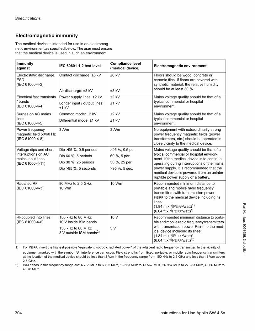
Specifications
Pa
rt Num
ber: 905358
6, 3rd edition
Electromagnetic immunity
The medical device is intended for use in an electromag-netic environment as specified below. The user must ensure that the medical device is used in such an environment.
Immunity against
IEC 60601-1-2 test levelCompliance level (medical device)
Electromagnetic environment
Electrostatic discharge, ESD (IEC 61000-4-2)
Contact discharge: ±6 kV ±6 kV Floors should be wood, concrete or ceramic tiles. If floors are covered with synthetic material, the relative humidity should be at least 30 %.Air discharge: ±8 kV ±8 kV
Electrical fast transients / bursts (IEC 61000-4-4)
Power supply lines: ±2 kV ±2 kV Mains voltage quality should be that of a typical commercial or hospital environment.
Longer input / output lines: ±1 kV
±1 kV
Surges on AC mains lines (IEC 61000-4-5)
Common mode: ±2 kV ±2 kV Mains voltage quality should be that of a typical commercial or hospital environment.
Differential mode: ±1 kV ±1 kV
Power frequency magnetic field 50/60 Hz (IEC 61000-4-8)
3 A/m 3 A/m No equipment with extraordinarily strong power frequency magnetic fields (power transformers, etc.) should be operated in close vicinity to the medical device.
Voltage dips and short interruptions on AC mains input lines(IEC 61000-4-11)
Dip >95 %, 0.5 periods >95 %, 0.5 per. Mains voltage quality should be that of a typical commercial or hospital environ-ment. If the medical device is to continue operating during interruptions of the mains power supply, it is recommended that the medical device is powered from an uninter-ruptible power supply or a battery.
Dip 60 %, 5 periods 60 %, 5 per.
Dip 30 %, 25 periods 30 %, 25 per.
Dip >95 %, 5 seconds >95 %, 5 sec.
Radiated RF (IEC 61000-4-3)
80 MHz to 2.5 GHz:10 V/m
10 V/m Recommended minimum distance to portable and mobile radio frequency transmitters with transmission power PEIRP to the medical device including its lines:(1.84 m x √PEIRP/watt)1)
(6.04 ft x √PEIRP/watt)1)
RFcoupled into lines(IEC 61000-4-6)
150 kHz to 80 MHz: 10 V inside ISM bands
10 V Recommended minimum distance to porta-ble and mobile radio frequency transmitters with transmission power PEIRP to the med-ical device including its lines:(1.84 m x √PEIRP/watt)1)
(6.04 ft x √PEIRP/watt)1))
150 kHz to 80 MHz:3 V outside ISM bands2)
3 V
1) For PEIRP, insert the highest possible "equivalent isotropic radiated power" of the adjacent radio frequency transmitter. In the vicinity of
equipment marked with the symbol , interference can occur. Field strengths from fixed, portable, or mobile radio frequency transmitters at the location of the medical device should be less than 3 V/m in the frequency range from 150 kHz to 2.5 GHz and less than 1 V/m above 2.5 GHz.
2) ISM bands in this frequency range are: 6.765 MHz to 6.795 MHz, 13.553 MHz to 13.567 MHz, 26.957 MHz to 27.283 MHz, 40.66 MHz to 40.70 MHz.
304 Instructions for Use Apollo SW 4.5n
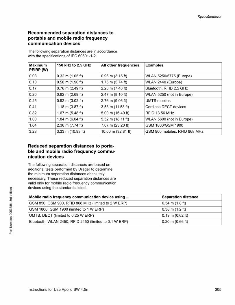
Specifications
Par
t Num
ber:
905
3586
, 3rd
edi
tion
Recommended separation distances to portable and mobile radio frequency communication devices
The following separation distances are in accordance with the specifications of IEC 60601-1-2.
Reduced separation distances to porta-ble and mobile radio frequency commu-nication devices
The following separation distances are based on additional tests performed by Dräger to determine the minimum separation distances absolutely necessary. These reduced separation distances are valid only for mobile radio frequency communication devices using the standards listed.
Maximum PEIRP (W)
150 kHz to 2.5 GHz All other frequencies Examples
0.03 0.32 m (1.05 ft) 0.96 m (3.15 ft) WLAN 5250/5775 (Europe)
0.10 0.58 m (1.90 ft) 1.75 m (5.74 ft) WLAN 2440 (Europe)
0.17 0.76 m (2.49 ft) 2.28 m (7.48 ft) Bluetooth, RFID 2.5 GHz
0.20 0.82 m (2.69 ft) 2.47 m (8.10 ft) WLAN 5250 (not in Europe)
0.25 0.92 m (3.02 ft) 2.76 m (9.06 ft) UMTS mobiles
0.41 1.18 m (3.87 ft) 3.53 m (11.58 ft) Cordless DECT devices
0.82 1.67 m (5.48 ft) 5.00 m (16.40 ft) RFID 13.56 MHz
1.00 1.84 m (6.04 ft) 5.52 m (18.11 ft) WLAN 5600 (not in Europe)
1.64 2.36 m (7.74 ft) 7.07 m (23.20 ft) GSM 1800/GSM 1900
3.28 3.33 m (10.93 ft) 10.00 m (32.81 ft) GSM 900 mobiles, RFID 868 MHz
Mobile radio frequency communication device using ... Separation distance
GSM 850, GSM 900, RFID 868 MHz (limited to 2 W ERP) 0.54 m (1.8 ft)
GSM 1800, GSM 1900 (limited to 1 W ERP) 0.38 m (1.2 ft)
UMTS, DECT (limited to 0.25 W ERP) 0.19 m (0.62 ft)
Bluetooth, WLAN 2450, RFID 2450 (limited to 0.1 W ERP) 0.20 m (0.66 ft)
Instructions for Use Apollo SW 4.5n 305

Specifications
Pa
rt Num
ber: 905358
6, 3rd edition
Device combinationsThis device can be operated in combination with other Dräger devices or with devices from other manufacturers. Observe the accompanying documents for the individual devices.
If a device combination is not approved by Dräger, the safety and the functional state of the individual devices can be compromised. The operating organization must ensure that the device combination complies with the applicable editions of the relevant standards for medical devices.
Device combinations approved by Dräger meet the requirements of the following standards:
– IEC 60601-1, 3rd edition (general requirements for safety, device combinations, software-controlled functions)
– IEC 60601-1-2 (electromagnetic compatibility)
– IEC 60601-1-8 (alarm systems)
Or:
– IEC 60601-1, 2nd edition (general requirements for safety)
– IEC 60601-1-1 (device combinations)
– IEC 60601-1-2 (electromagnetic compatibility)
– IEC 60601-1-4 (software-controlled functions)
– IEC 60601-1-8 (alarm systems)
Connections to IT-networksData can be exchanged across an IT-network by using hard-wired and wireless technologies. An IT-network can be any data interface (e.g., RS232, LAN, USB, printer interface) that is described in standards and conventions.
During operation, this device can exchange information with other devices and support the following functions by means of IT-networks:
– Display of waveforms and parameter data
– Signaling of alarms
– Transfer of device settings and patient data
Connecting this device to a network that incorporates other devices or making subsequent changes to that network can lead to new risks for patients, users, and third parties. Before the device is connected to the network or the network is changed, these risks must be identified, analyzed, and evaluated, and appropriate measures must be taken.
306 Instructions for Use Apollo SW 4.5n
Specifications
Par
t Num
ber:
905
3586
, 3rd
edi
tion
Examples of subsequent changes to the network:
– Changing the network configuration
– Removing devices from the network
– Adding new devices to the network
– Performing upgrades or updates on devices that are connected to the network
Information on connecting to the IT-net-work
Prerequisites
This device must only be connected to the network by service personnel. The IT representative of the hospital must be consulted in advance.
The following documents must be observed:
– Accompanying documents of this device
– Descriptions of the network
– Description of the network-based alarm systems
Dräger recommends complying with IEC 80001-1 (risk management for IT-networks with medical devices).
Serial ports
The following interfaces are supported:
– RS232 interfaces conforming to EIA RS-232 (CCITT V.24/V.28) for the following applications:
– MEDIBUS, MEDIBUS.X
– Connections with third party medical devices
Consequences of using an inappropriate network
If the network does not meet the requirements, hazardous situations can result. The following situations can occur with this device:
– Due to an insecure decentralized alarm system:
– Alarms are not transmitted.
– Alarms or data is transmitted with a delay.
– False alarms are triggered.
– During an interruption of the network connection:
– Alarms are not transmitted.
– Suppressed alarms or alarm tones are not reactivated, but remain suppressed.
Instructions for Use Apollo SW 4.5n 307
Specifications
Pa
rt Num
ber: 905358
6, 3rd edition
– Without firewall and antivirus software:
– Data are not protected.
– Device settings are changed.
– The device generates false alarms or does not generate alarms.
– Data are sent incomplete, sent to the wrong device, or not sent at all.
– Patient data are intercepted, falsified, or damaged.
– Data have incorrect time stamps.
Requirements on the electrical characteristics of connected devices and networks
The serial ports are only suitable for connection of devices or networks that have a rated voltage of at most 24 V DC on the network side and that meet the requirements of one of the following standards:
– IEC 60950-1: Ungrounded SELV circuits
– IEC 60601-1 (as of 2nd edition): Touchable secondary circuits
Relevant standards
In addition to the standards listed here, the medical device also complies with various other standards, e.g., standards concerning special national requirements.
IEC 60601-1 2nd ed.Medical electrical equipment
Part 1:Requirements for safety
IEC 60601-1-2Medical electrical equipment
Part 1-2:General requirements for safety,Collateral standard: Electromagnetic compatibility; Requirements and tests
IEC 60601-1-8Medical electrical equipment
Part 1-8:General requirements for safety,Collateral standard: General requirements, tests and guidance for alarm systems in medical electrical systems
IEC 60601-2-13Medical electrical equipment
Part 2-13:Particular requirements for the safety of anaesthetic systems
ISO 8835-2Systems for inhalational anaesthesia
Part 2:Anaesthetic breathing systems
ISO 8835-3Systems for inhalational anaesthesia
Part 3:Transfer and receiving systems ofactive anaesthetic gas scavenging systems
ISO 8835-4 Part 4:Anaesthetic vapour delivery devices
ISO 8835-5Systems for inhalational anaesthesia
Part 5:Anaesthetic ventilators
308 Instructions for Use Apollo SW 4.5n
Specifications
Par
t Num
ber:
905
3586
, 3rd
edi
tion
ISO 9919Medical electrical equipment
Particular requirements for basic safety and essential performance of pulse oximeter equipment for medical use
ISO 21647Medical electrical equipment
Particular requirements for basic safety and essential performance of respi-ratory gas monitors
For devices from production date July 2015 the following also applies:
IEC 60601-1 3rd ed.Medical electrical equipment
Part 1:General requirements for basic safety and essential performance
IEC 60601-1-2Medical electrical equipment
Part 1-2:General requirements for safety - Collateral standard: Electromagnetic compatibility - Requirements and tests
IEC 60601-1-8 Part 1-8:General requirements for safety including essential performance character-istics - Collateral standard: Alarm systems - General requirements, tests and guidance for alarm systems in medical electrical equipment and medi-cal electrical systems
ISO 80601-2-13Medical electrical equipment
Part 2-13:Particular requirements for basic safety and essential performance of an an-aesthetic workstation
ISO 80601-2-55 Part 2-55:Particular requirements for the basic safety and essential performance of respiratory gas monitors
Instructions for Use Apollo SW 4.5n 309

These Instructions for Use apply only toApollo SW 4.5nwith Serial No.:
Without Serial No. filled in by Dräger, these instructions for use are provided for general information only and do not apply to a specific medical device.These instructions for use are provided for customer information only and are only updated or exchanged upon customer request.
Manufacturer:
Dräger Medical GmbH
Moislinger Allee 53 – 55
D-23542 Lübeck
Germany
+49 451 8 82-0
FAX +49 451 8 82-20 80
http://www.draeger.com
9053586 – GA 5132.510 enUS© Dräger Medical GmbHEdition: 5 – 2016-01(Edition: 1 – 2012-01) Dräger reserves the right to make modifications to the equipment withouprior notice
As of 2015-08:Dräger Medical GmbHchanges toDrägerwerk AG & Co. KGaA
As of 2016-05:Draeger Medical, Inc.changes toDraeger, Inc.
Distributed by:
Draeger Medical, Inc.
3135 Quarry Road
Telford, PA 18969
U.S.A.
(215) 721-5400
(800) 4DRAGER (800 437-2437)
FAX (215) 723-5935
t


