8
Sapphire Series 2 Tier Horizontal Bed Head Console Instructions for Use / Installation Instructions w w w . a m i c o . c o m

Sapphire Series 2 Tier Horizontal Bed Head Console
Instructions for Use / Installation Instructions
w w w . a m i c o . c o m
1 Amico Corporation
Before Installation
NOTE: Unit installation should conform to local building codes
Instructions for Use
a) General information
• Instructions for use shall state which parts of the equipment are capable of bearing additional loads. The maximum safe working load shall be stated.
• If flexible hoses and hose assemblies are used for supplying medical gases, anesthetic gas scavenging or liquids in an operator-adjustable system (e.g. a ceiling pendant), the instructions for use shall include a procedure for, and the recommended frequency of, inspection and replacement.
• If flexible hoses are used for supplying medical gases in an operator-adjustable system (e.g., a ceiling pendant), the instructions for use shall state that the following tests given in EN ISO 7396.1 shall be carried out following modification or replacement of the flexible hose: • Test for leakage; • Test for obstruction; • Test for particulate contamination; • Test of gas identity
• If flexible hoses are used for supplying anaesthetic gas scavenging in an operator-adjustable system (e.g. a ceiling pendant), the instructions for use shall state that the following tests given in EN ISO 7396.2 shall be carried out following modification or replacement of the flexible hose: • Test for leakage; • Test of flow and pressure drop
• If flexible hoses are used for supplying liquids in an operator-adjustable system (e.g. a ceiling pendant), the instructions for use shall state that the following test, given in clause 59.103.2 b, shall be carried out following modification or replacement of the flexible hose: • Test for leakage
b) Responsibility of the manufacturer
The manufacturer shall provide evidence that the following production tests have been performed for eachmedical supply unit and that the specified requirements are met:
i. Impedance of protective earthing in accordance with 18 f ) of EN 60601-1:1990;ii. Earth leakage current in accordance with 19.3 and 19.4 of EN 60601-1:1990;iii. Dielectric strength in accordance with 20.3 and 20.4 of EN 60601-1:1990;iv. The following requirements and tests:
• Requirements as in 59.101.1, 59.102.1 and 59.103.1; • Flow and pressure drop in accordance with 59.101.2 a and 59.102.2 a; • No cross-connections in accordance with 59.101.2 b, 59.102.2 b and 59.103.2 a; • Leakage in accordance with 59.101.2.c, 59.102.2 c and 59.103.2.b; • Pressure tests in accordance with 59.101.2 d and 59.102.2.d.
c) Specifications for installation and use
Medical supply units shall be installed, tested and used in compliance with EN ISO 7396.2, EN ISO 7396.1 and the manufacturer's instructions.
NOTE 1: An IEC document has been prepared on this subject. (See IEC 60364-7-710)
NOTE 2: Consideration should be given to the mounting height of medical supply units in order to satisfy user requirements for illumination and viewed luminance and access to services.
www.amico.com 2
Before Installation
CAUTION: Please do not lift unit by the plastic end caps.
1. Review a copy of the final approved shop drawing(s). These documents will provide you with technical information specific to your installation, such as:
• Equipment types and quantities
• Room numbers and location
• Shop drawings of each unit type
• Wiring diagrams and rough-in locations
2. Locate the unit inside the crate that you wish to install. The contents of each crate are listed on the shipping document(s) and crate label.
The installation instructions provided are for Amico standard products. The product shipped to the job site may not be exactly as shown in the installation drawings used in this manual.
The Bed Head System is intended for use as a means to deliver medical gases, electrical services, communication devices and to manage medical equipment around the patient. The intended users of this product are healthcare employees who have the cognitive skills to use the product. Follow the facility safety protocols if an intended user does not have the cognitive skills to use the product safely. Only qualified technicians should service the bed head units.
The Sapphire is configured using Amico oxygen, air (medical air) and SAI (surgical air), nitrous oxide, vacuum and anesthetic gas scavenging outlets as required. Amico can also accommodate the use of third party outlets at the customer's request. The gas outlets manufactured by Amico are designed for use within the UK with gas-specific assembly and operation in mind to prevent interchangeability between the gases and associated secondary equipment. If orders are received for products being shipped into other countries (Germany, France, etc.) CE approved outlets for those countries will be supplied.
The pipe manifold will consist of copper pipes manufactured from phosphorus deoxidized, non-arsenical copper to BS EN 1412:1996 grade CW024A in metric diameters to BS EN 13348:2001. Pipe joining fittings will be end feed capillary fittings to BS EN 1254-1:1998.
The unit is capable of accommodating receptacles and switches for any international application which are installed and wired at Amico. Devices such as a nurse call and data outlets are provisioned for but are not wired.
Amico manufactures its products in accordance with job specific shop drawings and documents. The products comply to industry standards including HTM 2022, HTM02-01, HTM08-03, BS EN ISO 11197, BS EN60601-1, BS 6496, BS 7671, BS EN 60439 and IEC 60364-7-710.
!
3 Amico Corporation
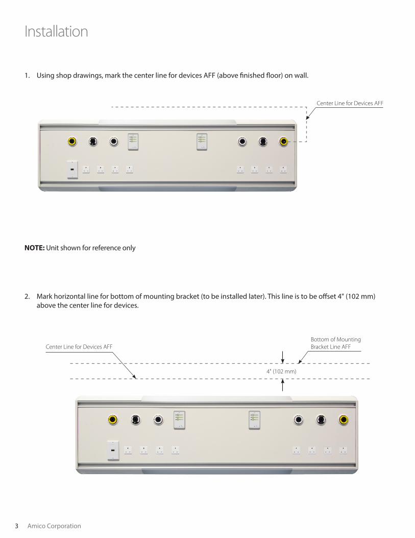
1. Using shop drawings, mark the center line for devices AFF (above finished floor) on wall.
Installation
Center Line for Devices AFF
2. Mark horizontal line for bottom of mounting bracket (to be installed later). This line is to be offset 4" (102 mm) above the center line for devices.
NOTE: Unit shown for reference only
Bottom of MountingBracket Line AFF
4" (102 mm)
Center Line for Devices AFF
www.amico.com 4
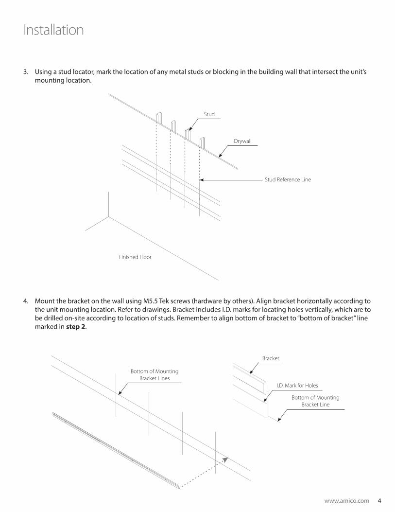
3. Using a stud locator, mark the location of any metal studs or blocking in the building wall that intersect the unit’s mounting location.
Installation
Stud
Drywall
Stud Reference Line
Finished Floor
4. Mount the bracket on the wall using M5.5 Tek screws (hardware by others). Align bracket horizontally according to the unit mounting location. Refer to drawings. Bracket includes I.D. marks for locating holes vertically, which are to be drilled on-site according to location of studs. Remember to align bottom of bracket to “bottom of bracket” line marked in step 2.
Bottom of MountingBracket Line
Bottom of MountingBracket Lines
Bracket
I.D. Mark for Holes
5 Amico Corporation
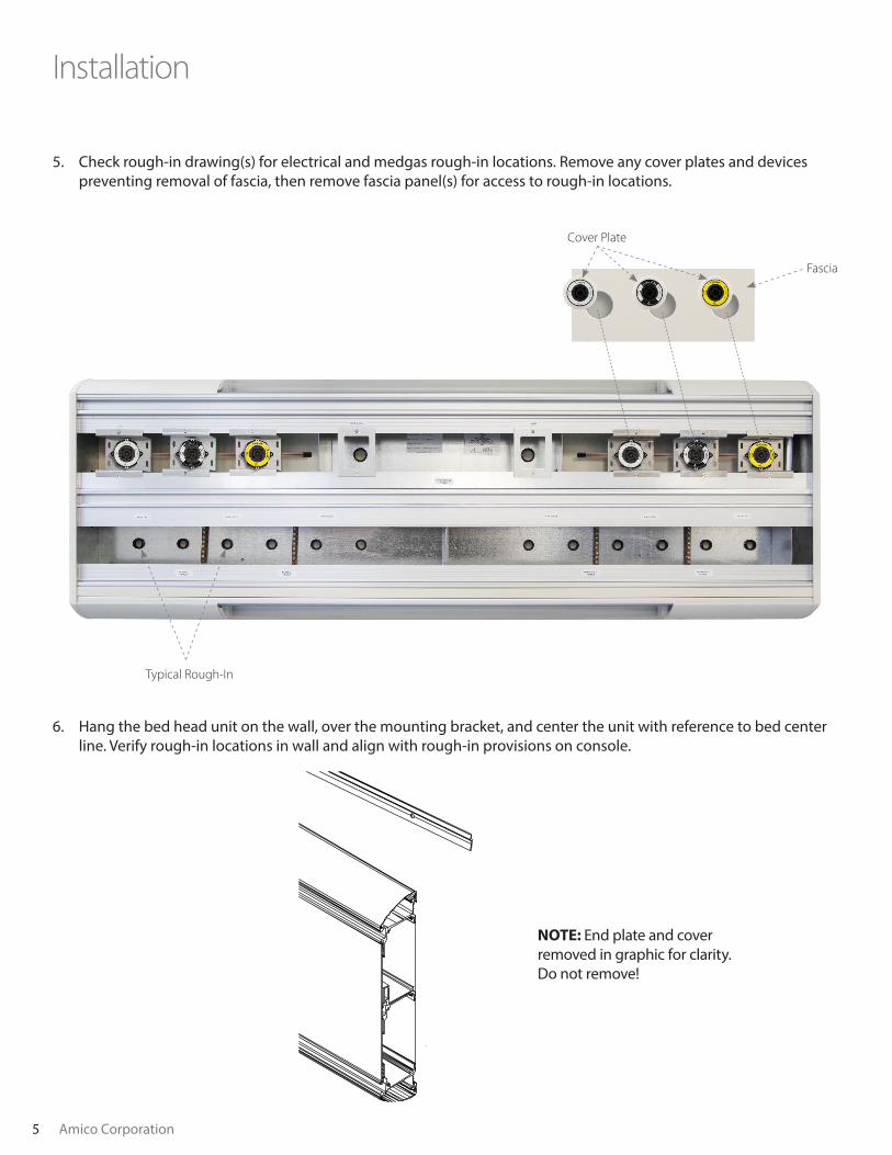
Installation
5. Check rough-in drawing(s) for electrical and medgas rough-in locations. Remove any cover plates and devices preventing removal of fascia, then remove fascia panel(s) for access to rough-in locations.
Typical Rough-In
Fascia
Cover Plate
NOTE: End plate and cover removed in graphic for clarity. Do not remove!
6. Hang the bed head unit on the wall, over the mounting bracket, and center the unit with reference to bed center line. Verify rough-in locations in wall and align with rough-in provisions on console.
www.amico.com 6
Installation
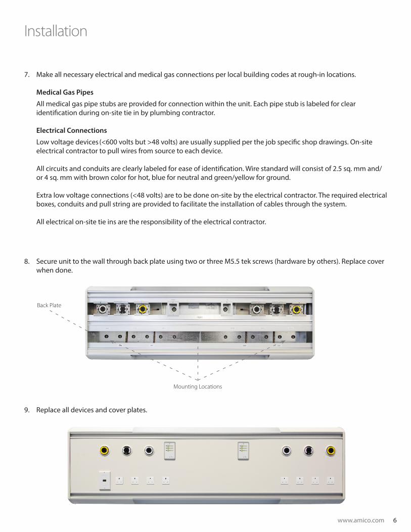
8. Secure unit to the wall through back plate using two or three M5.5 tek screws (hardware by others). Replace cover when done.
9. Replace all devices and cover plates.
Mounting Locations
Back Plate
7. Make all necessary electrical and medical gas connections per local building codes at rough-in locations. Medical Gas Pipes
All medical gas pipe stubs are provided for connection within the unit. Each pipe stub is labeled for clear identification during on-site tie in by plumbing contractor. Electrical Connections
Low voltage devices (<600 volts but >48 volts) are usually supplied per the job specific shop drawings. On-site electrical contractor to pull wires from source to each device. All circuits and conduits are clearly labeled for ease of identification. Wire standard will consist of 2.5 sq. mm and/or 4 sq. mm with brown color for hot, blue for neutral and green/yellow for ground. Extra low voltage connections (<48 volts) are to be done on-site by the electrical contractor. The required electrical boxes, conduits and pull string are provided to facilitate the installation of cables through the system. All electrical on-site tie ins are the responsibility of the electrical contractor.
C US LISTEDC US LISTEDC US LISTED
AC-IM-SAPH-CNSL-2T 01.08.2016
www.amico.com
Amico Corporation | www.amico.com
85 Fulton Way, Richmond HillOntario, L4B 2N4, Canada
Toll Free Tel: 1.877.264.2697Toll Free Fax: 1.866.440.4986Tel: 905.763.7778 Fax: 905.763.8587Email: [email protected]
Authorized Representative:RMS-UK Limited28 Trinity RoadNailsea, SomersetBS484NU EnglandPhone & Fax: 01275 858891


