26
Chemin de la madone 69210 LENTILLY Tél : + 33 (0) 4 74 72 12 69 Fax : + 33 (0) 4 74 72 10 01 E – mail : [email protected] www.duc-helices.com INSTRUCTIONS MANUAL OF THE SWIRL PROPELLER
Chemin de la madone 69210 LENTILLY
Tél : + 33 (0) 4 74 72 12 69
Fax : + 33 (0) 4 74 72 10 01
E – mail : [email protected]
www.duc-helices.com
INSTRUCTIONS MANUAL OF
THE SWIRL PROPELLER
DUC Hélices Company Chemin de la Madone
F-69210 LENTILLY – FRANCE Phone: +33 (0)4 74 72 12 69
Fax: +33 (0)4 74 72 10 01 [email protected]
www.duc-helices.com
DH_SW_NM_01_A-SWIRL-Instruction_Manual.docx 15/12/2009 2/26
Summary 1. Purpose ............................................................................................................................................ 3 2. Trade Reference .............................................................................................................................. 3 3. Identification ..................................................................................................................................... 3
3.1. Identification of the propeller ................................................................................................... 3 3.2. Identification of the blades ....................................................................................................... 3 3.1. Identification of the hub ........................................................................................................... 4 3.2. Identification of the accessories .............................................................................................. 4
4. Description of the propeller .............................................................................................................. 4 4.1. Characteristics ......................................................................................................................... 4 4.2. Carbon hub .............................................................................................................................. 5 4.3. Advantages .............................................................................................................................. 5 4.4. Option edge reinforced with an Inconel part ............................................................................ 6
5. Installation ........................................................................................................................................ 6 6. Applications ...................................................................................................................................... 7 7. Adjusting the blade angle ................................................................................................................. 8
7.1. Attack angle ............................................................................................................................. 8 7.2. Adjustment ............................................................................................................................... 8
8. Assembly .......................................................................................................................................... 9 8.1. Assembly and adjusting of the propeller ................................................................................. 9
9. Maintenance ................................................................................................................................... 13 9.1. Regular maintenance (Customer) ......................................................................................... 13 9.2. General maintenance (Client) ................................................................................................ 13 9.3. Complete maintenance (DUC Hélices) ................................................................................. 14
10. Cleaning & Repair ....................................................................................................................... 14 10.1. Cleaning products .................................................................................................................. 14 10.2. Repair kit ................................................................................................................................ 14
11. Appendices ................................................................................................................................. 16 I. Technical folder of the propeller hub CARBONE FORGE
® ........................................................ 16
II. Technical folder of the blade SWIRL STANDARD and INCONEL ............................................. 22
DUC Hélices Company Chemin de la Madone
F-69210 LENTILLY – FRANCE Phone: +33 (0)4 74 72 12 69
Fax: +33 (0)4 74 72 10 01 [email protected]
www.duc-helices.com
DH_SW_NM_01_A-SWIRL-Instruction_Manual.docx 15/12/2009 3/26
1. Purpose
The purpose of this document is to provide all necessary information relating to the use of propeller SWIRL.
2. Trade Reference
01-03-001 Three-blade SWIRL, right 01-03-002 Three-blade SWIRL, left 01-05-001 Three-blade Inconel SWIRL, right 01-05-002 Three-blade Inconel SWIRL, left
3. Identification
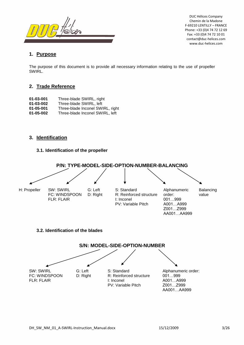
3.1. Identification of the propeller
P/N: TYPE-MODEL-SIDE-OPTION-NUMBER-BALANCING
H: Propeller SW: SWIRL FC: WINDSPOON FLR: FLAIR
G: Left D: Right
S: Standard R: Reinforced structure I: Inconel PV: Variable Pitch
Alphanumeric order: 001…999 A001…A999 Z001…Z999 AA001…AA999
Balancing value
3.2. Identification of the blades
S/N: MODEL-SIDE-OPTION-NUMBER
SW: SWIRL FC: WINDSPOON FLR: FLAIR
G: Left D: Right
S: Standard R: Reinforced structure I: Inconel PV: Variable Pitch
Alphanumeric order: 001…999 A001…A999 Z001…Z999 AA001…AA999
DUC Hélices Company Chemin de la Madone
F-69210 LENTILLY – FRANCE Phone: +33 (0)4 74 72 12 69
Fax: +33 (0)4 74 72 10 01 [email protected]
www.duc-helices.com
DH_SW_NM_01_A-SWIRL-Instruction_Manual.docx 15/12/2009 4/26
3.1. Identification of the hub
S/N: TYPE-MODEL-NUMBER/NUMBER
M: Hub 2P: Two-blade 3P: Three-blade 5P: 5 blades
Alphanumeric order: 001…999 A001…A999 Z001…Z999 AA001…AA999
Alphanumeric order: 001…999 A001…A999 Z001…Z999 AA001…AA999
There are 2 numbers for the hub because it is an assembly of 2 similar half-hub.
3.2. Identification of the accessories
S/N: TYPE-MODEL-NUMBER
C: Spinner P: Mounting plate
210: Ø 210 mm 250: Ø 250 mm
Alphanumeric order: 001…999 A001…A999 Z001…Z999 AA001…AA999
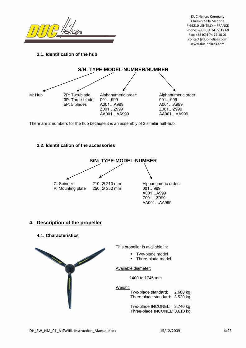
4. Description of the propeller
4.1. Characteristics
This propeller is available in:
Two-blade model Three-blade model
Available diameter: 1400 to 1745 mm Weight:
Two-blade standard: 2.680 kg Three-blade standard: 3.520 kg
Two-blade INCONEL: 2.740 kg Three-blade INCONEL: 3.610 kg
DUC Hélices Company Chemin de la Madone
F-69210 LENTILLY – FRANCE Phone: +33 (0)4 74 72 12 69
Fax: +33 (0)4 74 72 10 01 [email protected]
www.duc-helices.com
DH_SW_NM_01_A-SWIRL-Instruction_Manual.docx 15/12/2009 5/26
This propeller was studied to have a “constant speed” effect. The blades are manufactured with part of carbon plies and their design was carried out to obtain maximum strains in torsion and inflection. It’s why the constant speed effect is not dependent on the blade distortion but on its geometry and its particular profile. Because of the extra flat profile and a small cord, we obtain an excellent output as well:
In performance
In noise
In consumption
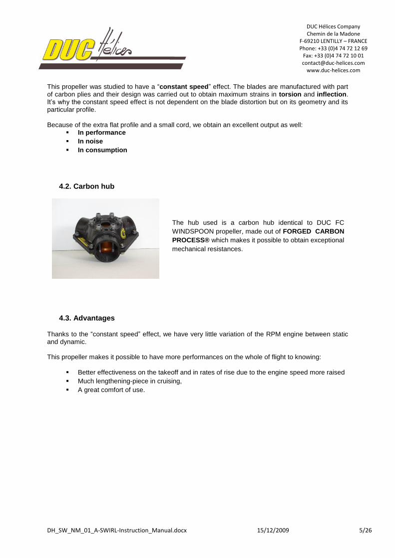
4.2. Carbon hub
4.3. Advantages
Thanks to the “constant speed” effect, we have very little variation of the RPM engine between static and dynamic. This propeller makes it possible to have more performances on the whole of flight to knowing:
Better effectiveness on the takeoff and in rates of rise due to the engine speed more raised
Much lengthening-piece in cruising,
A great comfort of use.
The hub used is a carbon hub identical to DUC FC
WINDSPOON propeller, made out of FORGED CARBON
PROCESS® which makes it possible to obtain exceptional
mechanical resistances.
DUC Hélices Company Chemin de la Madone
F-69210 LENTILLY – FRANCE Phone: +33 (0)4 74 72 12 69
Fax: +33 (0)4 74 72 10 01 [email protected]
www.duc-helices.com
DH_SW_NM_01_A-SWIRL-Instruction_Manual.docx 15/12/2009 6/26
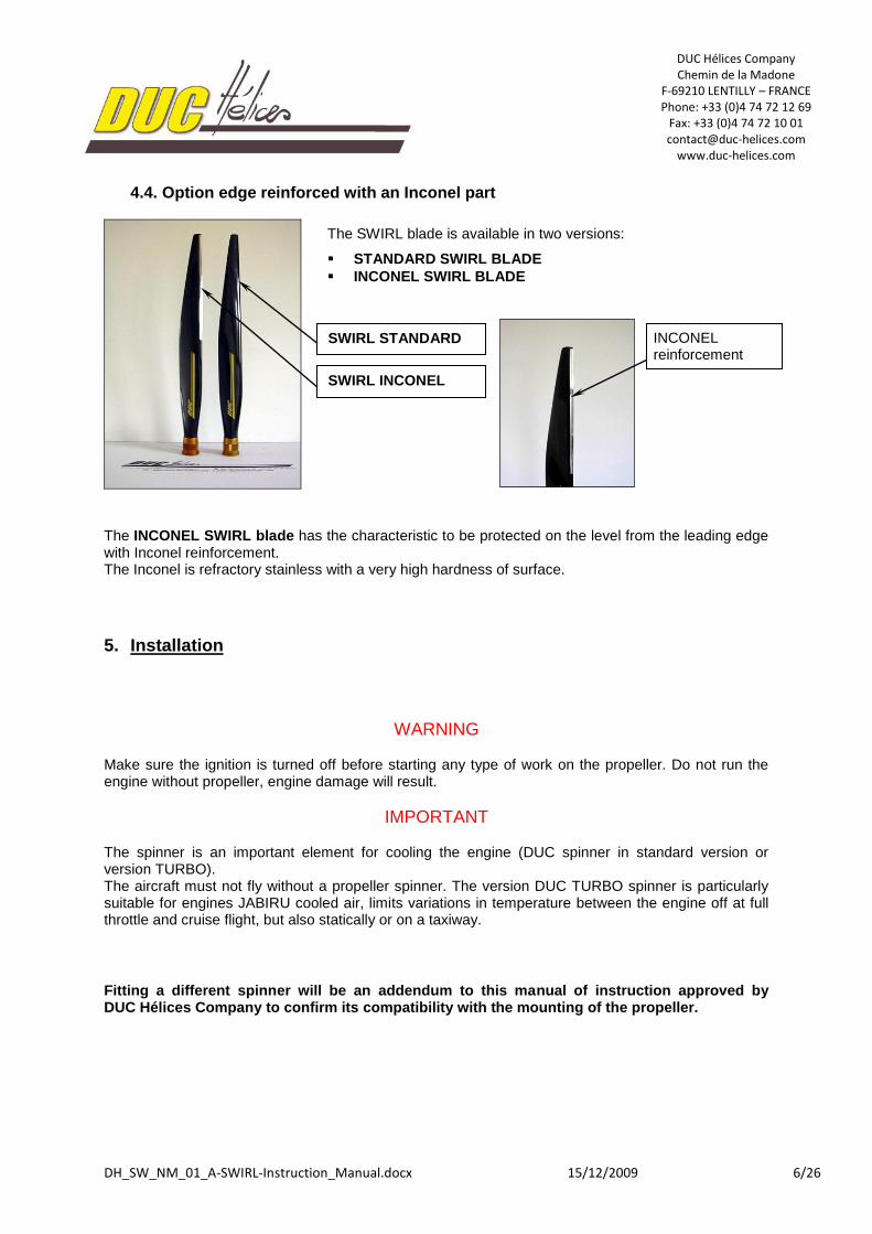
4.4. Option edge reinforced with an Inconel part
The INCONEL SWIRL blade has the characteristic to be protected on the level from the leading edge with Inconel reinforcement. The Inconel is refractory stainless with a very high hardness of surface.
5. Installation
WARNING Make sure the ignition is turned off before starting any type of work on the propeller. Do not run the engine without propeller, engine damage will result.
IMPORTANT The spinner is an important element for cooling the engine (DUC spinner in standard version or version TURBO). The aircraft must not fly without a propeller spinner. The version DUC TURBO spinner is particularly suitable for engines JABIRU cooled air, limits variations in temperature between the engine off at full throttle and cruise flight, but also statically or on a taxiway.
Fitting a different spinner will be an addendum to this manual of instruction approved by DUC Hélices Company to confirm its compatibility with the mounting of the propeller.
The SWIRL blade is available in two versions:
STANDARD SWIRL BLADE
INCONEL SWIRL BLADE
SWIRL STANDARD
SWIRL INCONEL
INCONEL reinforcement
DUC Hélices Company Chemin de la Madone
F-69210 LENTILLY – FRANCE Phone: +33 (0)4 74 72 12 69
Fax: +33 (0)4 74 72 10 01 [email protected]
www.duc-helices.com
DH_SW_NM_01_A-SWIRL-Instruction_Manual.docx 15/12/2009 7/26
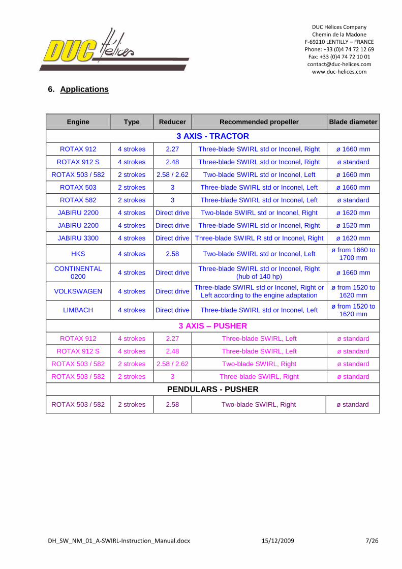
6. Applications
Engine Type Reducer Recommended propeller Blade diameter
3 AXIS - TRACTOR
ROTAX 912 4 strokes 2.27 Three-blade SWIRL std or Inconel, Right ø 1660 mm
ROTAX 912 S 4 strokes 2.48 Three-blade SWIRL std or Inconel, Right ø standard
ROTAX 503 / 582 2 strokes 2.58 / 2.62 Two-blade SWIRL std or Inconel, Left ø 1660 mm
ROTAX 503 2 strokes 3 Three-blade SWIRL std or Inconel, Left ø 1660 mm
ROTAX 582 2 strokes 3 Three-blade SWIRL std or Inconel, Left ø standard
JABIRU 2200 4 strokes Direct drive Two-blade SWIRL std or Inconel, Right ø 1620 mm
JABIRU 2200 4 strokes Direct drive Three-blade SWIRL std or Inconel, Right ø 1520 mm
JABIRU 3300 4 strokes Direct drive Three-blade SWIRL R std or Inconel, Right ø 1620 mm
HKS 4 strokes 2.58 Two-blade SWIRL std or Inconel, Left ø from 1660 to
1700 mm
CONTINENTAL 0200
4 strokes Direct drive Three-blade SWIRL std or Inconel, Right
(hub of 140 hp) ø 1660 mm
VOLKSWAGEN 4 strokes Direct drive Three-blade SWIRL std or Inconel, Right or
Left according to the engine adaptation ø from 1520 to
1620 mm
LIMBACH 4 strokes Direct drive Three-blade SWIRL std or Inconel, Left ø from 1520 to
1620 mm
3 AXIS – PUSHER
ROTAX 912 4 strokes 2.27 Three-blade SWIRL, Left ø standard
ROTAX 912 S 4 strokes 2.48 Three-blade SWIRL, Left ø standard
ROTAX 503 / 582 2 strokes 2.58 / 2.62 Two-blade SWIRL, Right ø standard
ROTAX 503 / 582 2 strokes 3 Three-blade SWIRL, Right ø standard
PENDULARS - PUSHER
ROTAX 503 / 582 2 strokes 2.58 Two-blade SWIRL, Right ø standard
DUC Hélices Company Chemin de la Madone
F-69210 LENTILLY – FRANCE Phone: +33 (0)4 74 72 12 69
Fax: +33 (0)4 74 72 10 01 [email protected]
www.duc-helices.com
DH_SW_NM_01_A-SWIRL-Instruction_Manual.docx 15/12/2009 8/26
7. Adjusting the blade angle
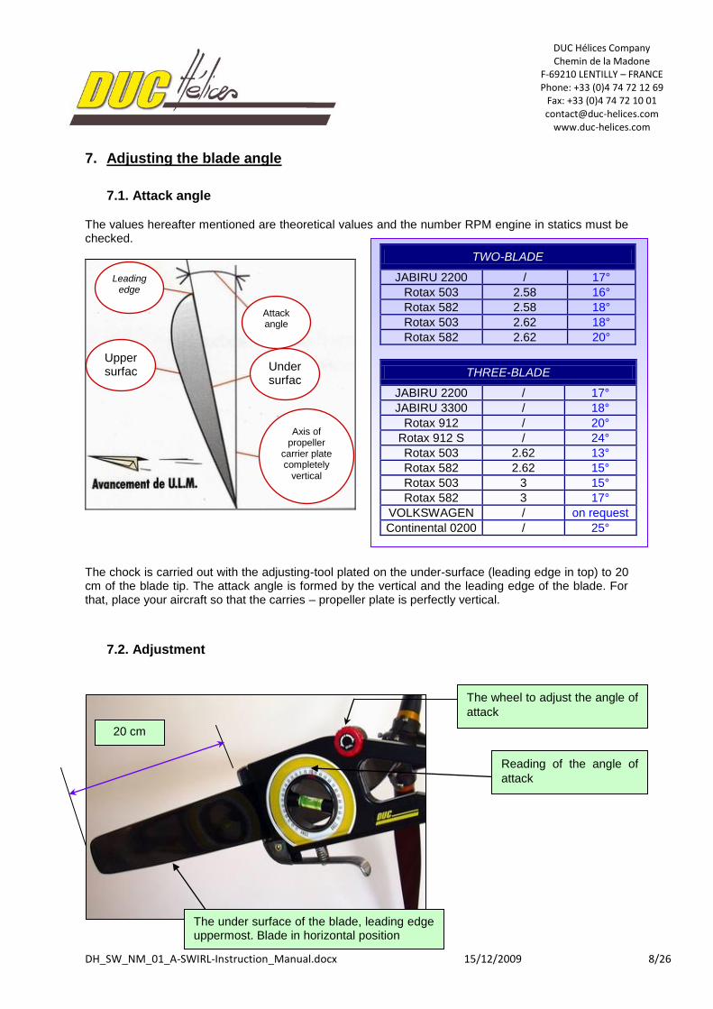
7.1. Attack angle
The values hereafter mentioned are theoretical values and the number RPM engine in statics must be checked.
FVSVSVS
The chock is carried out with the adjusting-tool plated on the under-surface (leading edge in top) to 20 cm of the blade tip. The attack angle is formed by the vertical and the leading edge of the blade. For that, place your aircraft so that the carries – propeller plate is perfectly vertical.
7.2. Adjustment
TWO-BLADE
JABIRU 2200 / 17°
Rotax 503 2.58 16°
Rotax 582 2.58 18°
Rotax 503 2.62 18°
Rotax 582 2.62 20°
THREE-BLADE
JABIRU 2200 / 17°
JABIRU 3300 / 18°
Rotax 912 / 20°
Rotax 912 S / 24°
Rotax 503 2.62 13°
Rotax 582 2.62 15°
Rotax 503 3 15°
Rotax 582 3 17°
VOLKSWAGEN / on request
Continental 0200 / 25°
Leading edge
Upper surfac
e
Attack angle
Under surfac
e
Axis of propeller
carrier plate completely
vertical
20 cm
The wheel to adjust the angle of
attack
Reading of the angle of
attack
The under surface of the blade, leading edge uppermost. Blade in horizontal position
DUC Hélices Company Chemin de la Madone
F-69210 LENTILLY – FRANCE Phone: +33 (0)4 74 72 12 69
Fax: +33 (0)4 74 72 10 01 [email protected]
www.duc-helices.com
DH_SW_NM_01_A-SWIRL-Instruction_Manual.docx 15/12/2009 9/26
8. Assembly
8.1. Assembly and adjusting of the propeller
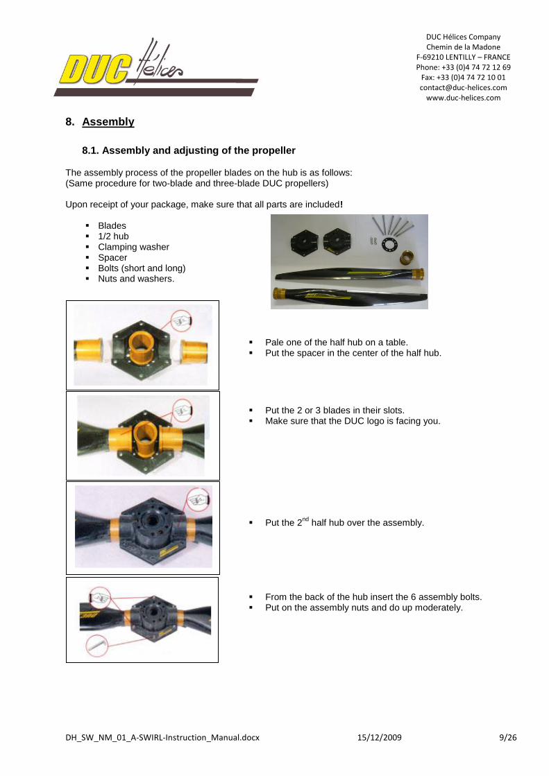
The assembly process of the propeller blades on the hub is as follows: (Same procedure for two-blade and three-blade DUC propellers) Upon receipt of your package, make sure that all parts are included!
Blades 1/2 hub Clamping washer Spacer Bolts (short and long) Nuts and washers.
Pale one of the half hub on a table. Put the spacer in the center of the half hub.
Put the 2 or 3 blades in their slots. Make sure that the DUC logo is facing you.
Put the 2nd
half hub over the assembly.
From the back of the hub insert the 6 assembly bolts. Put on the assembly nuts and do up moderately.
DUC Hélices Company Chemin de la Madone
F-69210 LENTILLY – FRANCE Phone: +33 (0)4 74 72 12 69
Fax: +33 (0)4 74 72 10 01 [email protected]
www.duc-helices.com
DH_SW_NM_01_A-SWIRL-Instruction_Manual.docx 15/12/2009 10/26
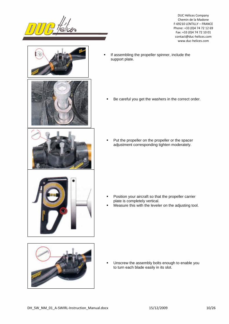
If assembling the propeller spinner, include the
support plate.
Be careful you get the washers in the correct order.
Put the propeller on the propeller or the spacer adjustment corresponding tighten moderately.
Position your aircraft so that the propeller carrier plate is completely vertical.
Measure this with the leveler on the adjusting tool.
Unscrew the assembly bolts enough to enable you to turn each blade easily in its slot.
DUC Hélices Company Chemin de la Madone
F-69210 LENTILLY – FRANCE Phone: +33 (0)4 74 72 12 69
Fax: +33 (0)4 74 72 10 01 [email protected]
www.duc-helices.com
DH_SW_NM_01_A-SWIRL-Instruction_Manual.docx 15/12/2009 11/26
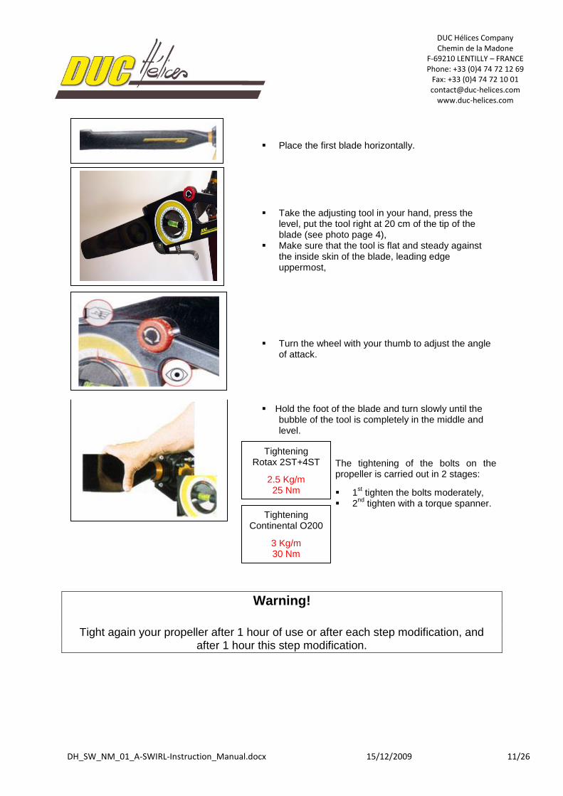
Place the first blade horizontally.
Take the adjusting tool in your hand, press the level, put the tool right at 20 cm of the tip of the blade (see photo page 4),
Make sure that the tool is flat and steady against the inside skin of the blade, leading edge uppermost,
Turn the wheel with your thumb to adjust the angle of attack.
Hold the foot of the blade and turn slowly until the
bubble of the tool is completely in the middle and level.
The tightening of the bolts on the propeller is carried out in 2 stages:
1st tighten the bolts moderately,
2nd
tighten with a torque spanner.
Warning!
Tight again your propeller after 1 hour of use or after each step modification, and
after 1 hour this step modification.
Tightening Rotax 2ST+4ST
2.5 Kg/m 25 Nm
Tightening Continental O200
3 Kg/m 30 Nm
DUC Hélices Company Chemin de la Madone
F-69210 LENTILLY – FRANCE Phone: +33 (0)4 74 72 12 69
Fax: +33 (0)4 74 72 10 01 [email protected]
www.duc-helices.com
DH_SW_NM_01_A-SWIRL-Instruction_Manual.docx 15/12/2009 12/26
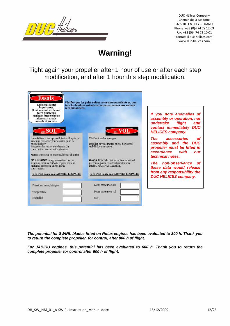
Warning!
Tight again your propeller after 1 hour of use or after each step modification, and after 1 hour this step modification.
The potential for SWIRL blades fitted on Rotax engines has been evaluated to 800 h. Thank you to return the complete propeller, for control, after 800 h of flight. For JABIRU engines, this potential has been evaluated to 600 h. Thank you to return the complete propeller for control after 600 h of flight.
If you note anomalies of assembly or operation, not undertake flight and contact immediately DUC HELICES company.
The accessories of assembly and the DUC propeller must be fitted in accordance with our technical notes.
The non-observance of these data would release from any responsibility the DUC HELICES company.
DUC Hélices Company Chemin de la Madone
F-69210 LENTILLY – FRANCE Phone: +33 (0)4 74 72 12 69
Fax: +33 (0)4 74 72 10 01 [email protected]
www.duc-helices.com
DH_SW_NM_01_A-SWIRL-Instruction_Manual.docx 15/12/2009 13/26
9. Maintenance
9.1. Regular maintenance (Customer)
For a safety use of the SWIRL propeller, it is necessary that the user performs regular maintenance to detect any abnormalities. This maintenance is usually just a simple check. Frequency of checking: Each pre-flight
Control methods: - Visual inspection - Manual handling
Checkpoints: - Fixation of the propeller: Manually maintaining the tip of a blade of the propeller, shake it firmly to feel if a too much clearance appears in the setting of the propeller.
- Degradation of material: Check visually the entire propeller
without dismantling (blade root, Inconel leading edge, surface of the blade, spinner, hub, etc.)
- Fixation of the spinner: Check visually the fixation screws of the spinner. A marking paint can be made between each screw and spinner to have a means of visual inspection of proper tightening the screws.
Possible problems: - Too much clearance in the propeller fixation - Degradation of surface / Crack apparent - Screw unscrewed or damaged
Corrective actions: Depending on the importance: 1. See paragraph 10 Maintenance & Repair 2. Tighten the screws to proper torque 3. Replace(s) damage component(s) 4. Contact DUC Hélices to define a solution
9.2. General maintenance (Client)
A general maintenance by the customer must be made at lower frequency. Frequency of checking: Every 100 hours or annually
Control methods: - Visual inspection - Torque wrench
Checkpoints: - Fixation of the propeller: By removing the spinner of the propeller, check the proper tightening of the screws to the wrench. These screws of the hub should be tightened to proper torque, defined in the installation instructions attached.
A marking paint of all the screw/washer/hub after tightening can be done to help make a visual check outside of the general maintenance.
- Degradation of material: Check visually the entire propeller (blade root, Inconel leading edge, surface of the blade, spinner, hub, etc.)
DUC Hélices Company Chemin de la Madone
F-69210 LENTILLY – FRANCE Phone: +33 (0)4 74 72 12 69
Fax: +33 (0)4 74 72 10 01 [email protected]
www.duc-helices.com
DH_SW_NM_01_A-SWIRL-Instruction_Manual.docx 15/12/2009 14/26
Possible problems: - Too much clearance in the propeller fixation - Degradation of surface / Crack apparent - Screw unscrewed or damaged
Corrective actions: Depending on the importance: 1. See paragraph 10 Maintenance & Repair 2. Tighten the screws to proper torque 3. Replace(s) damage component(s) 4. Contact DUC Hélices to define a solution
9.3. Complete maintenance (DUC Hélices)
After many hours of use (potential) defined by DUC, the propeller must be returned to the company for a full expertise of all components of the propeller. For Rotax engines, the potential for SWIRL propeller was estimated at 800 hours. For Jabiru engines, the potential for SWIRL propeller was estimated at 600 hours. The possible degradation of the propeller components may vary depending on the location of use.
10. Cleaning & Repair
10.1. Cleaning products
10.2. Repair kit
Repairs are limited to filling small nicks in the blades. These repairs can be made from cuts of maximum dimensions following: Leading edge: - 2 mm deep
- 30 mm in length Intrados/Extrados: - 0.5 mm deep - 30mm in length
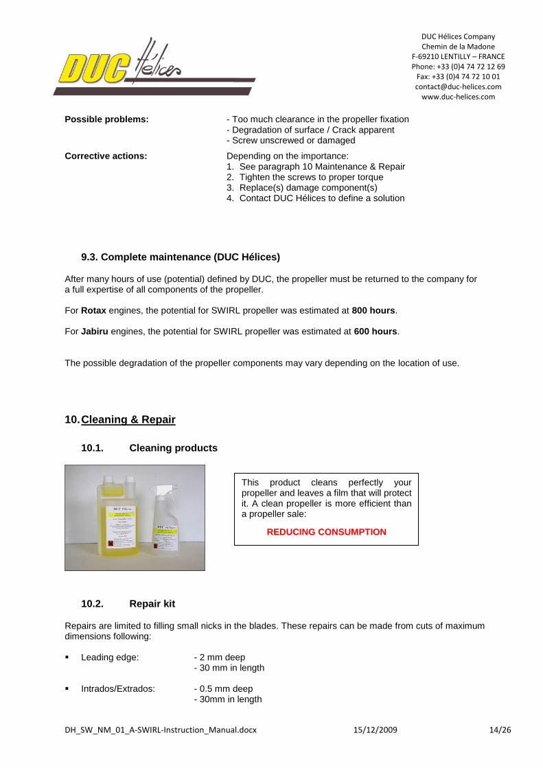
This product cleans perfectly your propeller and leaves a film that will protect it. A clean propeller is more efficient than a propeller sale:
REDUCING CONSUMPTION
DUC Hélices Company Chemin de la Madone
F-69210 LENTILLY – FRANCE Phone: +33 (0)4 74 72 12 69
Fax: +33 (0)4 74 72 10 01 [email protected]
www.duc-helices.com
DH_SW_NM_01_A-SWIRL-Instruction_Manual.docx 15/12/2009 15/26
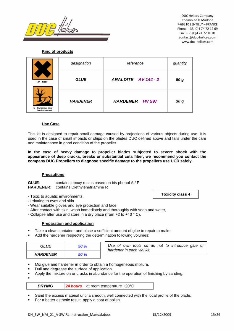
Kind of products
designation reference quantity
GLUE ARALDITE AV 144 - 2 50 g
HARDENER HARDENER HV 997 30 g
Use Case
This kit is designed to repair small damage caused by projections of various objects during use. It is used in the case of small impacts or chips on the blades DUC defined above and falls under the care and maintenance in good condition of the propeller. In the case of heavy damage to propeller blades subjected to severe shock with the appearance of deep cracks, breaks or substantial cuts fiber, we recommend you contact the company DUC Propellers to diagnose specific damage to the propellers use UCR safely.
Precautions
GLUE: contains epoxy resins based on bis phenol A / F HARDENER: contains Diethylenetriamine R
- Toxic to aquatic environments, - Irritating to eyes and skin - Wear suitable gloves and eye protection and face - After contact with skin, wash immediately and thoroughly with soap and water, - Collapse after use and store in a dry place (from +2 to +40 ° C).
Preparation and application
Take a clean container and place a sufficient amount of glue to repair to make. Add the hardener respecting the determination following volumes:
GLUE 50 %
HARDENER 50 %
Mix glue and hardener in order to obtain a homogeneous mixture. Dull and degrease the surface of application. Apply the mixture on or cracks in abundance for the operation of finishing by sanding.
DRYING 24 hours at room temperature +20°C
Sand the excess material until a smooth, well connected with the local profile of the blade. For a better esthetic result, apply a coat of polish.
Use of own tools so as not to introduce glue or hardener in each vial kit.
Toxicity class 4
DUC Hélices Company Chemin de la Madone
F-69210 LENTILLY – FRANCE Phone: +33 (0)4 74 72 12 69
Fax: +33 (0)4 74 72 10 01 [email protected]
www.duc-helices.com
DH_SW_NM_01_A-SWIRL-Instruction_Manual.docx 15/12/2009 16/26
11. Appendices
I. Technical folder of the propeller hub CARBONE FORGE®
2 tests reports about the DUC propeller hub:
1. Comparative test of the mechanical resistance between a ½ hub foundry in aluminum and a ½ hub carbon made with the CARBONE FORGE
® technology.
2. Resistance test of the temperature: Measure of Tg.
INTRODUCTION
The objective of these tests is to evaluate the potential of parts made from the FORGED CARBON process. The composite half-hubs are compared to parts manufactured from 3 different aluminum grades. They are found to present comparable performances, while been much lighter.
MATERIALS AND PARTS
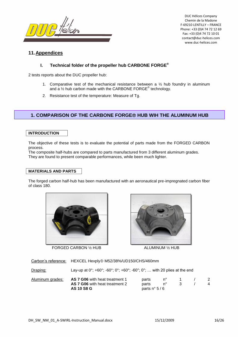
The forged carbon half-hub has been manufactured with an aeronautical pre-impregnated carbon fiber of class 180.
FORGED CARBON ½ HUB ALUMINUM ½ HUB
Carbon’s reference: HEXCEL Hexply M52/38%/UD150/CHS/460mm Draping: Lay-up at 0°; +60°; -60°; 0°; +60°; -60°; 0°; … with 20 plies at the end Aluminum grades: AS 7 G06 with heat treatment 1 parts n° 1 / 2 AS 7 G06 with heat treatment 2 parts n° 3 / 4 AS 10 S8 G parts n° 5 / 6
1. COMPARISON OF THE CARBONE FORGE HUB WIH THE ALUMINUM HUB
DUC Hélices Company Chemin de la Madone
F-69210 LENTILLY – FRANCE Phone: +33 (0)4 74 72 12 69
Fax: +33 (0)4 74 72 10 01 [email protected]
www.duc-helices.com
DH_SW_NM_01_A-SWIRL-Instruction_Manual.docx 15/12/2009 17/26
WEIGHT PARTS
Part n° Aluminum (g) Forged carbon (g)
1 537 270
2 509 272
3 520 268
4 - 270
5 528
6 525
As well as carbon hubs are almost half the weight of aluminum ones (expected, due to different material densities), we can see only few variation of their weight, from a part to another.
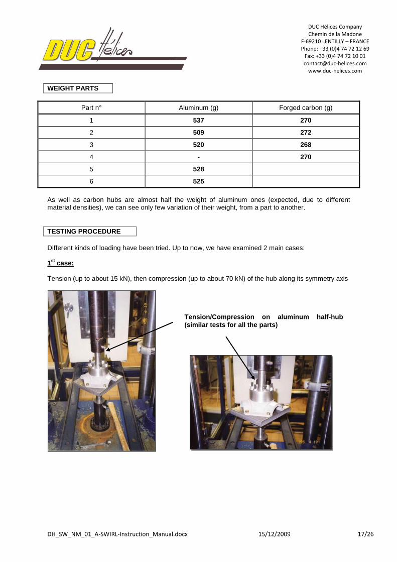
TESTING PROCEDURE
Different kinds of loading have been tried. Up to now, we have examined 2 main cases: 1
st case:
Tension (up to about 15 kN), then compression (up to about 70 kN) of the hub along its symmetry axis
Tension/Compression on aluminum half-hub
(similar tests for all the parts)
DUC Hélices Company Chemin de la Madone
F-69210 LENTILLY – FRANCE Phone: +33 (0)4 74 72 12 69
Fax: +33 (0)4 74 72 10 01 [email protected]
www.duc-helices.com
DH_SW_NM_01_A-SWIRL-Instruction_Manual.docx 15/12/2009 18/26
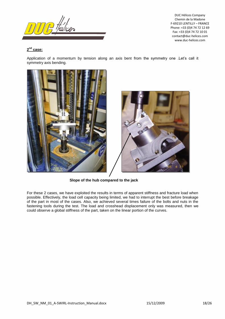
2nd
case: Application of a momentum by tension along an axis bent from the symmetry one .Let’s call it symmetry axis bending.
For these 2 cases, we have exploited the results in terms of apparent stiffness and fracture load when possible. Effectively, the load cell capacity being limited, we had to interrupt the best before breakage of the part in most of the cases. Also, we achieved several times failure of the bolts and nuts in the fastening tools during the test. The load and crosshead displacement only was measured, then we could observe a global stiffness of the part, taken on the linear portion of the curves.
Slope of the hub compared to the jack
DUC Hélices Company Chemin de la Madone
F-69210 LENTILLY – FRANCE Phone: +33 (0)4 74 72 12 69
Fax: +33 (0)4 74 72 10 01 [email protected]
www.duc-helices.com
DH_SW_NM_01_A-SWIRL-Instruction_Manual.docx 15/12/2009 19/26
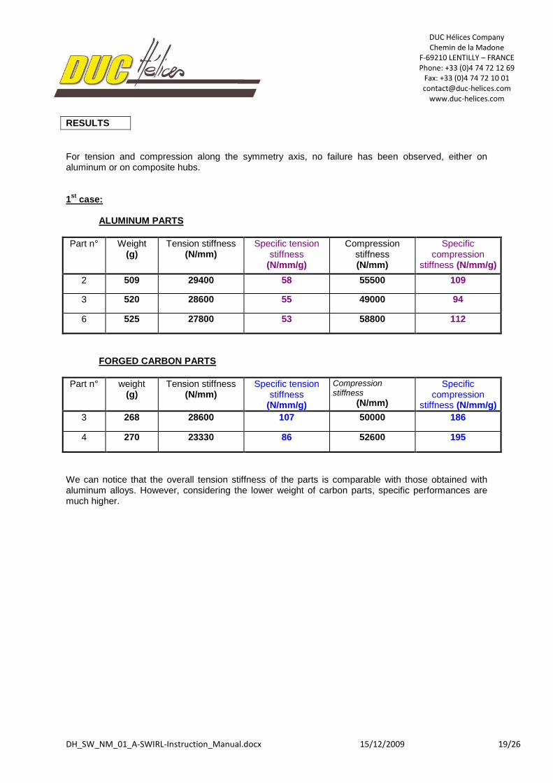
RESULTS
For tension and compression along the symmetry axis, no failure has been observed, either on aluminum or on composite hubs. 1
st case:
ALUMINUM PARTS
Part n° Weight (g)
Tension stiffness (N/mm)
Specific tension stiffness
(N/mm/g)
Compression stiffness (N/mm)
Specific compression
stiffness (N/mm/g)
2 509 29400 58 55500 109
3 520 28600 55 49000 94
6 525 27800 53 58800 112
FORGED CARBON PARTS
Part n° weight (g)
Tension stiffness (N/mm)
Specific tension stiffness
(N/mm/g)
Compression stiffness
(N/mm)
Specific compression
stiffness (N/mm/g)
3 268 28600 107 50000 186
4 270 23330 86 52600 195
We can notice that the overall tension stiffness of the parts is comparable with those obtained with aluminum alloys. However, considering the lower weight of carbon parts, specific performances are much higher.
DUC Hélices Company Chemin de la Madone
F-69210 LENTILLY – FRANCE Phone: +33 (0)4 74 72 12 69
Fax: +33 (0)4 74 72 10 01 [email protected]
www.duc-helices.com
DH_SW_NM_01_A-SWIRL-Instruction_Manual.docx 15/12/2009 20/26
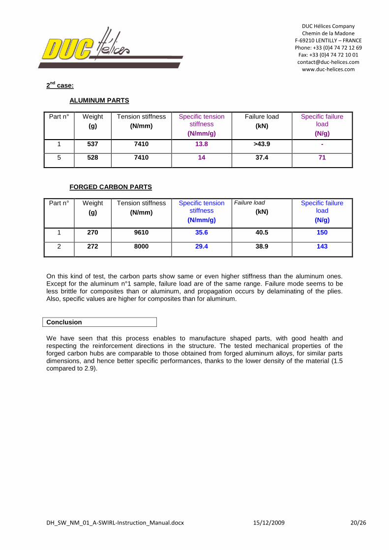
2nd
case:
ALUMINUM PARTS
Part n° Weight
(g)
Tension stiffness
(N/mm)
Specific tension stiffness
(N/mm/g)
Failure load
(kN)
Specific failure load
(N/g)
1 537 7410 13.8 >43.9 -
5 528 7410 14 37.4 71
FORGED CARBON PARTS
Part n° Weight
(g)
Tension stiffness
(N/mm)
Specific tension stiffness
(N/mm/g)
Failure load
(kN)
Specific failure load
(N/g)
1 270 9610 35.6 40.5 150
2 272 8000 29.4 38.9 143
On this kind of test, the carbon parts show same or even higher stiffness than the aluminum ones. Except for the aluminum n°1 sample, failure load are of the same range. Failure mode seems to be less brittle for composites than or aluminum, and propagation occurs by delaminating of the plies. Also, specific values are higher for composites than for aluminum.
Conclusion
We have seen that this process enables to manufacture shaped parts, with good health and respecting the reinforcement directions in the structure. The tested mechanical properties of the forged carbon hubs are comparable to those obtained from forged aluminum alloys, for similar parts dimensions, and hence better specific performances, thanks to the lower density of the material (1.5 compared to 2.9).
DUC Hélices Company Chemin de la Madone
F-69210 LENTILLY – FRANCE Phone: +33 (0)4 74 72 12 69
Fax: +33 (0)4 74 72 10 01 [email protected]
www.duc-helices.com
DH_SW_NM_01_A-SWIRL-Instruction_Manual.docx 15/12/2009 21/26
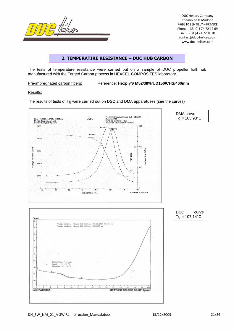
The tests of temperature resistance were carried out on a sample of DUC propeller half hub manufactured with the Forged Carbon process in HEXCEL COMPOSITES laboratory.
Pre-impregnated carbon fibers: Reference: Hexply M52/38%/UD150/CHS/460mm Results: The results of tests of Tg were carried out on DSC and DMA apparatuses.(see the curves)
2. TEMPERATIRE RESISTANCE – DUC HUB CARBON
DMA curve Tg = 103.93°C
DSC curve Tg = 107.14°C
DUC Hélices Company Chemin de la Madone
F-69210 LENTILLY – FRANCE Phone: +33 (0)4 74 72 12 69
Fax: +33 (0)4 74 72 10 01 [email protected]
www.duc-helices.com
DH_SW_NM_01_A-SWIRL-Instruction_Manual.docx 15/12/2009 22/26
II. Technical folder of the blade SWIRL STANDARD and INCONEL
1. Resistance of the SWIRL blade in STANDARD and INCONEL versions 2. Fatigue test of the DUC blade
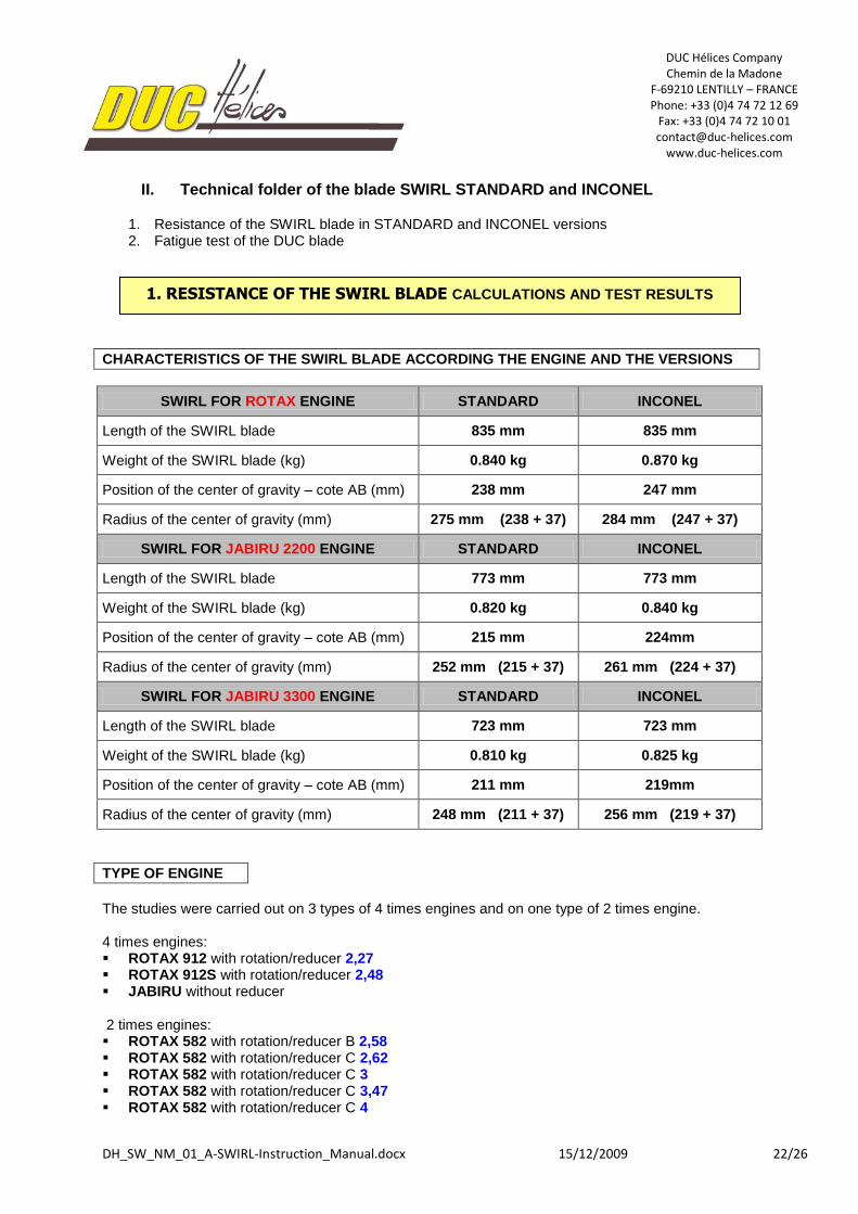
CHARACTERISTICS OF THE SWIRL BLADE ACCORDING THE ENGINE AND THE VERSIONS
SWIRL FOR ROTAX ENGINE STANDARD INCONEL
Length of the SWIRL blade 835 mm 835 mm
Weight of the SWIRL blade (kg) 0.840 kg 0.870 kg
Position of the center of gravity – cote AB (mm) 238 mm 247 mm
Radius of the center of gravity (mm) 275 mm (238 + 37) 284 mm (247 + 37)
SWIRL FOR JABIRU 2200 ENGINE STANDARD INCONEL
Length of the SWIRL blade 773 mm 773 mm
Weight of the SWIRL blade (kg) 0.820 kg 0.840 kg
Position of the center of gravity – cote AB (mm) 215 mm 224mm
Radius of the center of gravity (mm) 252 mm (215 + 37) 261 mm (224 + 37)
SWIRL FOR JABIRU 3300 ENGINE STANDARD INCONEL
Length of the SWIRL blade 723 mm 723 mm
Weight of the SWIRL blade (kg) 0.810 kg 0.825 kg
Position of the center of gravity – cote AB (mm) 211 mm 219mm
Radius of the center of gravity (mm) 248 mm (211 + 37) 256 mm (219 + 37)
TYPE OF ENGINE
The studies were carried out on 3 types of 4 times engines and on one type of 2 times engine. 4 times engines: ROTAX 912 with rotation/reducer 2,27 ROTAX 912S with rotation/reducer 2,48 JABIRU without reducer 2 times engines: ROTAX 582 with rotation/reducer B 2,58 ROTAX 582 with rotation/reducer C 2,62 ROTAX 582 with rotation/reducer C 3 ROTAX 582 with rotation/reducer C 3,47 ROTAX 582 with rotation/reducer C 4
1. RESISTANCE OF THE SWIRL BLADE CALCULATIONS AND TEST RESULTS
DUC Hélices Company Chemin de la Madone
F-69210 LENTILLY – FRANCE Phone: +33 (0)4 74 72 12 69
Fax: +33 (0)4 74 72 10 01 [email protected]
www.duc-helices.com
DH_SW_NM_01_A-SWIRL-Instruction_Manual.docx 15/12/2009 23/26
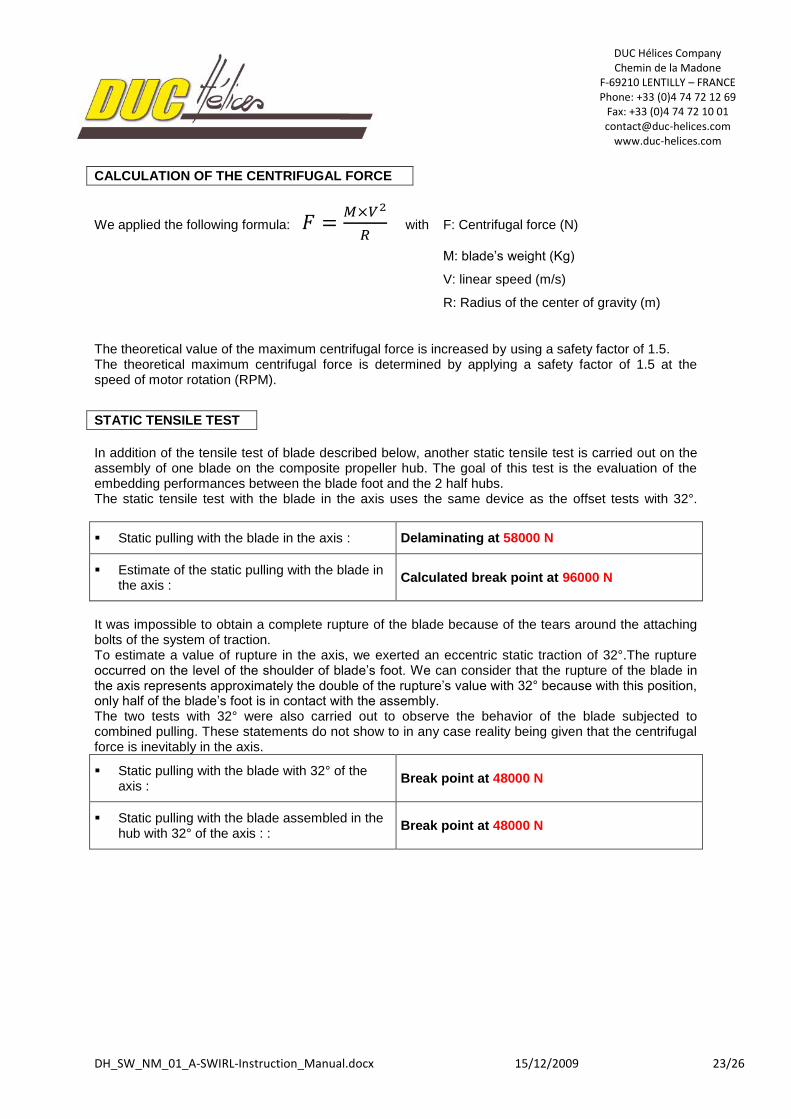
CALCULATION OF THE CENTRIFUGAL FORCE
We applied the following formula: with F: Centrifugal force (N)
M: blade’s weight (Kg)
V: linear speed (m/s)
R: Radius of the center of gravity (m)
The theoretical value of the maximum centrifugal force is increased by using a safety factor of 1.5. The theoretical maximum centrifugal force is determined by applying a safety factor of 1.5 at the speed of motor rotation (RPM).
STATIC TENSILE TEST
In addition of the tensile test of blade described below, another static tensile test is carried out on the assembly of one blade on the composite propeller hub. The goal of this test is the evaluation of the embedding performances between the blade foot and the 2 half hubs. The static tensile test with the blade in the axis uses the same device as the offset tests with 32°.
Static pulling with the blade in the axis : Delaminating at 58000 N
Estimate of the static pulling with the blade in the axis :
Calculated break point at 96000 N
It was impossible to obtain a complete rupture of the blade because of the tears around the attaching bolts of the system of traction. To estimate a value of rupture in the axis, we exerted an eccentric static traction of 32°.The rupture occurred on the level of the shoulder of blade’s foot. We can consider that the rupture of the blade in the axis represents approximately the double of the rupture’s value with 32° because with this position, only half of the blade’s foot is in contact with the assembly. The two tests with 32° were also carried out to observe the behavior of the blade subjected to combined pulling. These statements do not show to in any case reality being given that the centrifugal force is inevitably in the axis.
Static pulling with the blade with 32° of the axis :
Break point at 48000 N
Static pulling with the blade assembled in the hub with 32° of the axis : :
Break point at 48000 N
DUC Hélices Company Chemin de la Madone
F-69210 LENTILLY – FRANCE Phone: +33 (0)4 74 72 12 69
Fax: +33 (0)4 74 72 10 01 [email protected]
www.duc-helices.com
DH_SW_NM_01_A-SWIRL-Instruction_Manual.docx 15/12/2009 24/26
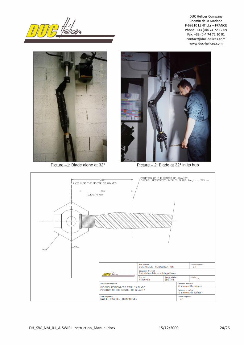
Picture –1: Blade alone at 32° Picture – 2: Blade at 32° in its hub
DUC Hélices Company Chemin de la Madone
F-69210 LENTILLY – FRANCE Phone: +33 (0)4 74 72 12 69
Fax: +33 (0)4 74 72 10 01 [email protected]
www.duc-helices.com
DH_SW_NM_01_A-SWIRL-Instruction_Manual.docx 15/12/2009 25/26
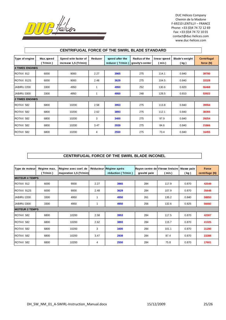
CENTRIFUGAL FORCE OF THE SWIRL BLADE STANDARD
CENTRIFUGAL FORCE OF THE SWIRL BLADE INCONEL
Type of engine Max.speed Speed witn factor of Reducer speed after the Radius of the linear speed Blade's weight Centrifugal
( Tr/min ) increase 1,5 (Tr/min) reducer ( Tr/min ) gravity's center ( m/s ) ( kg ) force (N)
4 TIMES ENGINES
ROTAX 912 6000 9000 2.27 3965 275 114.1 0.840 39780
ROTAX 912S 6000 9000 2.48 3629 275 104.5 0.840 33328
JABIRU 2200 3300 4950 1 4950 252 130.6 0.820 55468
JABIRU 3300 3300 4950 1 4950 248 128.5 0.810 53922
2 TIMES ENGINES
ROTAX 582 6800 10200 2.58 3953 275 113.8 0.840 39554
ROTAX 582 6800 10200 2.62 3893 275 112.1 0.840 38355
ROTAX 582 6800 10200 3 3400 275 97.9 0.840 29254
ROTAX 582 6800 10200 3.47 2939 275 84.6 0.840 21866
ROTAX 582 6800 10200 4 2550 275 73.4 0.840 16455
Type de moteur Régime max. Régime avec coef. de Réducteur Régime après Rayon centre de Vitesse linéaire Masse pale Force
( Tr/min ) majoration 1,5 (Tr/min) réduction ( Tr/min ) gravité pale ( m/s ) ( kg ) centrifuge (N)
MOTEUR 4 TEMPS
ROTAX 912 6000 9000 2.27 3965 284 117.9 0.870 42549
ROTAX 912S 6000 9000 2.48 3629 284 107.9 0.870 35648
JABIRU 2200 3300 4950 1 4950 261 135.2 0.840 58850
JABIRU 3300 3300 4950 1 4950 256 132.6 0.825 56692
MOTEUR 2 TEMPS
ROTAX 582 6800 10200 2.58 3953 284 117.5 0.870 42307
ROTAX 582 6800 10200 2.62 3893 284 115.7 0.870 41025
ROTAX 582 6800 10200 3 3400 284 101.1 0.870 31290
ROTAX 582 6800 10200 3.47 2939 284 87.4 0.870 23388
ROTAX 582 6800 10200 4 2550 284 75.8 0.870 17601
DUC Hélices Company Chemin de la Madone
F-69210 LENTILLY – FRANCE Phone: +33 (0)4 74 72 12 69
Fax: +33 (0)4 74 72 10 01 [email protected]
www.duc-helices.com
DH_SW_NM_01_A-SWIRL-Instruction_Manual.docx 15/12/2009 26/26
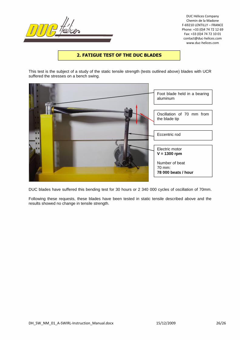
This test is the subject of a study of the static tensile strength (tests outlined above) blades with UCR suffered the stresses on a bench swing.
DUC blades have suffered this bending test for 30 hours or 2 340 000 cycles of oscillation of 70mm. Following these requests, these blades have been tested in static tensile described above and the results showed no change in tensile strength.
2. FATIGUE TEST OF THE DUC BLADES
Foot blade held in a bearing aluminum
Electric motor V = 1300 rpm Number of beat 70 mm:
78 000 beats / hour
Eccentric rod
Oscillation of 70 mm from the blade tip


