23
GA-E 211 / USA 2014-08 V3.0 / ECO 2014-0330 OPTIFLOW Single Sheath (Operating Hysteroscope) 8974351 Instructions

GA-E 211 / USA 2014-08 V3.0 / ECO 2014-0330
OPTIFLOW Single Sheath(Operating Hysteroscope)
8974351
Instructions
0 GA--E 211
Important general instructions for use
Ensure that this product is used only as intended and described in this instructionmanual, by ade-quately trained and qualified personnel, and that maintenance and repair is only carried out byauthorized specialized technicians.
Use this product only with the combinations and with the accessories and spare parts listed inthis instruction manual. Use other combinations, accessories and replacement parts only if theyare expressly intended for this use and if the performance and safety requirements are met.
Reprocess the products before every application and before returning them for repair as requiredby the instruction manual in order to protect the patient, user or third parties.
Subject to technical changes!Due to continuous development of our products, illustrations and technical data may deviateslightly from the data in this manual.
CAUTION :Federal law restricts this device to sale by or on the order of a physician.
Safety instructions and levels of danger
Symbol Level of danger
WARNING!Failure to observe can result in death or serious injury.
CAUTION!Failure to observe can result in slight injury or damage to the product.
. IMPORTANT!Failure to observe can result in damage to the product or surrounding.
. NOTE!Tips for optimum use and other useful information.
USARICHARD WOLFMedical Instruments Corp.353 Corporate Woods ParkwayVernon Hills, Illinois 60061Telephone: +1 847--913--1113Telefax: +1 847--913--1488sales&[email protected]
GERMANYRICHARD WOLF GmbH75438 KnittlingenPforzheimerstr. 32Telephone: +49 70 43 35--0Telefax: +49 70 43 [email protected]
UKRICHARD WOLF UK Ltd.Waterside WayWimbledonSW17 0HBTelephone: + 44 20 89 44 74 47Telefax: + 44 20 89 44 [email protected]
BELGIUM / NETHERLANDSN.V. EndoscopieRICHARD WOLF Belgium S.A.Industriezone DrongenLandegemstraat 69031 Gent DrongenTelephone: +32 92 80 81 00Telefax: +32 92 82 92 [email protected]
FRANCERICHARD WOLF France S.A.R.L.Rue Daniel BergerZ.A.C. La Neuvillette51100 ReimsTelephone: +33 3 26 87 02 89Telefax: +33 3 26 87 60 33
AUSTRIARICHARD WOLF AustriaGes.m.b.H.Wilhelminenstraße 93 a1160 ViennaTelephone: +43 14 05 51 51Telefax: +43 14 05 51 51 [email protected]
Marketing OfficeU.A.ERICHARD WOLF Middle EastP.O. Box 500283AL Thuraya Tower 19th Floor,Room 904, DubaiTelephone: + 9 71 43 68 19 20Telefax: + 9 71 43 68 61 12
INDIARICHARD WOLF India Private Ltd.JMD Pacific SquareNo. 211 A, Second FloorBehind 32nd MilestoneGurgaon -- 122 001National Capitol RegionTelephone: + 91 12 44 31 57 00Telefax: + 91 12 44 31 57 05

Contents
IGA--E 211
1 Technical description 1. . . . . . . . . . . . . . . . . . . . . . . . . . . . . . . . . . . . . . . . . . . . . . . . . . . . .
2 Intended use 1. . . . . . . . . . . . . . . . . . . . . . . . . . . . . . . . . . . . . . . . . . . . . . . . . . . . . . . . . . . . . .
3 Indications and field of use 1. . . . . . . . . . . . . . . . . . . . . . . . . . . . . . . . . . . . . . . . . . . . . . . .
4 Contraindications 1. . . . . . . . . . . . . . . . . . . . . . . . . . . . . . . . . . . . . . . . . . . . . . . . . . . . . . . . .
5 Combinations 2. . . . . . . . . . . . . . . . . . . . . . . . . . . . . . . . . . . . . . . . . . . . . . . . . . . . . . . . . . . . .
6 Illustration 3. . . . . . . . . . . . . . . . . . . . . . . . . . . . . . . . . . . . . . . . . . . . . . . . . . . . . . . . . . . . . . . .6.1 Legend and identification 3. . . . . . . . . . . . . . . . . . . . . . . . . . . . . . . . . . . . . . . . . . . . . . . . . . . .
7 Use 5. . . . . . . . . . . . . . . . . . . . . . . . . . . . . . . . . . . . . . . . . . . . . . . . . . . . . . . . . . . . . . . . . . . . . .7.1 Preparation 5. . . . . . . . . . . . . . . . . . . . . . . . . . . . . . . . . . . . . . . . . . . . . . . . . . . . . . . . . . . . . . . .7.1.1 Inserting PANOVIEW endoscope (1) into OPTIFLOW single sheath (2) 5. . . . . . . . . . . .7.1.2 Assembling ergonomic handle (3) 6. . . . . . . . . . . . . . . . . . . . . . . . . . . . . . . . . . . . . . . . . . . .7.1.3 Connecting PANOVIEW endoscope (1) to system components 6. . . . . . . . . . . . . . . . . . .7.2 Continuous irrigation mode 7. . . . . . . . . . . . . . . . . . . . . . . . . . . . . . . . . . . . . . . . . . . . . . . . . .7.3 CO2 mode 8. . . . . . . . . . . . . . . . . . . . . . . . . . . . . . . . . . . . . . . . . . . . . . . . . . . . . . . . . . . . . . . . .7.4 Additional notes and instructions for use 9. . . . . . . . . . . . . . . . . . . . . . . . . . . . . . . . . . . . . . .7.4.1 Light 9. . . . . . . . . . . . . . . . . . . . . . . . . . . . . . . . . . . . . . . . . . . . . . . . . . . . . . . . . . . . . . . . . . . . . .7.4.2 Current 9. . . . . . . . . . . . . . . . . . . . . . . . . . . . . . . . . . . . . . . . . . . . . . . . . . . . . . . . . . . . . . . . . . .7.4.3 Image quality 9. . . . . . . . . . . . . . . . . . . . . . . . . . . . . . . . . . . . . . . . . . . . . . . . . . . . . . . . . . . . . .7.4.4 Irrigation fluid 9. . . . . . . . . . . . . . . . . . . . . . . . . . . . . . . . . . . . . . . . . . . . . . . . . . . . . . . . . . . . . .7.5 HF application 10. . . . . . . . . . . . . . . . . . . . . . . . . . . . . . . . . . . . . . . . . . . . . . . . . . . . . . . . . . . . .7.6 Laser application 10. . . . . . . . . . . . . . . . . . . . . . . . . . . . . . . . . . . . . . . . . . . . . . . . . . . . . . . . . . .7.7 Inserting auxiliary instruments 11. . . . . . . . . . . . . . . . . . . . . . . . . . . . . . . . . . . . . . . . . . . . . . . .
8 Checks 12. . . . . . . . . . . . . . . . . . . . . . . . . . . . . . . . . . . . . . . . . . . . . . . . . . . . . . . . . . . . . . . . . . .8.1 Visual check 12. . . . . . . . . . . . . . . . . . . . . . . . . . . . . . . . . . . . . . . . . . . . . . . . . . . . . . . . . . . . . . .8.2 Functional check 12. . . . . . . . . . . . . . . . . . . . . . . . . . . . . . . . . . . . . . . . . . . . . . . . . . . . . . . . . . .8.2.1 Stopcock plug (2.9.1) 13. . . . . . . . . . . . . . . . . . . . . . . . . . . . . . . . . . . . . . . . . . . . . . . . . . . . . . .8.2.2 PANOVIEW endoscope (1) 13. . . . . . . . . . . . . . . . . . . . . . . . . . . . . . . . . . . . . . . . . . . . . . . . . .
9 Reprocessing and maintenance 14. . . . . . . . . . . . . . . . . . . . . . . . . . . . . . . . . . . . . . . . . . . .9.1 Disassembly before cleaning 14. . . . . . . . . . . . . . . . . . . . . . . . . . . . . . . . . . . . . . . . . . . . . . . . .9.1.1 Stopcock plug (2.9.1) 14. . . . . . . . . . . . . . . . . . . . . . . . . . . . . . . . . . . . . . . . . . . . . . . . . . . . . . .9.2 Manual reprocessing 14. . . . . . . . . . . . . . . . . . . . . . . . . . . . . . . . . . . . . . . . . . . . . . . . . . . . . . . .9.3 Machine reprocessing 15. . . . . . . . . . . . . . . . . . . . . . . . . . . . . . . . . . . . . . . . . . . . . . . . . . . . . . .9.4 Checks 15. . . . . . . . . . . . . . . . . . . . . . . . . . . . . . . . . . . . . . . . . . . . . . . . . . . . . . . . . . . . . . . . . . .9.5 Assembly before sterilization 15. . . . . . . . . . . . . . . . . . . . . . . . . . . . . . . . . . . . . . . . . . . . . . . . .9.5.1 Stopcock plug (2.9.1) 15. . . . . . . . . . . . . . . . . . . . . . . . . . . . . . . . . . . . . . . . . . . . . . . . . . . . . . .9.6 Sterilization 15. . . . . . . . . . . . . . . . . . . . . . . . . . . . . . . . . . . . . . . . . . . . . . . . . . . . . . . . . . . . . . . .9.6.1 Steam sterilization 15. . . . . . . . . . . . . . . . . . . . . . . . . . . . . . . . . . . . . . . . . . . . . . . . . . . . . . . . . .9.6.2 Gas sterilization 15. . . . . . . . . . . . . . . . . . . . . . . . . . . . . . . . . . . . . . . . . . . . . . . . . . . . . . . . . . . .9.6.3 High--Level--Disinfection 15. . . . . . . . . . . . . . . . . . . . . . . . . . . . . . . . . . . . . . . . . . . . . . . . . . . . .
10 Technical data and order data 16. . . . . . . . . . . . . . . . . . . . . . . . . . . . . . . . . . . . . . . . . . . . . .
11 Spare parts and accessories 16. . . . . . . . . . . . . . . . . . . . . . . . . . . . . . . . . . . . . . . . . . . . . . .
12 Operating, storage, transport and shipping conditions 17. . . . . . . . . . . . . . . . . . . . . .12.1 Disposal of product, packaging material and accessories 17. . . . . . . . . . . . . . . . . . . . . . . .
13 Literature 18. . . . . . . . . . . . . . . . . . . . . . . . . . . . . . . . . . . . . . . . . . . . . . . . . . . . . . . . . . . . . . . . .
14 Warranty and Customer Service 20. . . . . . . . . . . . . . . . . . . . . . . . . . . . . . . . . . . . . . . . . . . .
1 GA--E 211
1 Technical descriptionThe Operating Hysteroscope consists of the following components:
Z PANOVIEW endoscopeZ OPTIFLOW single sheathZ Ergonomic handleZ Auxiliary instruments
2 Intended useOperating Hysteroscopes are used for visualizing and inflating the cervical channel,the cavum uteri and the tube ostia (using liquid or CO2 gas). They are applied viathe natural passage.Furthermore this instrument can also be used for diagnosing the lower urinary tract.
Z PANOVIEW endoscope' for visualizing the inside of the patient via the natural passage.
Z OPTIFLOW single sheath' houses and automatically locks the PANOVIEW endoscope.' for supplying the dilation medium via the supply stopcock.' for inserting auxiliary instruments into the working channel via the insertion stop-cock.
' for pressure regulation and draining of the dilation medium via the drain stop-cock.
Z Ergonomic handle' housed and fixes the OPTIFLOW single sheath.' for fatigue--free work.
3 Indications and field of useFor examination, diagnosis and therapy in gynecology (hysteroscopy) or Cystos-copy in conjunction with endoscopic accessories.
The following examinations represent indications:
Z Gynecology (hysteroscopy)'Abnormal bleedings' Infertility'Complaints in the lower abdomen'Myomas, polyps, ablation of the endometrium' Tube sterilization
Z Cystoscopy'Urine incontinence'Bladder checke. g. during hysterectomy or TVT
. NOTE !We recommend reading relevant literature regarding the planned use.' see also section 13 “Literature”
4 ContraindicationsZ Acute inflammation of the lower abdomenZ Infection of the vaginaZ Pregnancy
Contraindications directly related to the product are presently unknown.On the basis of the patient’s general condition the physician/surgeon in chargemust decide whether the planned use is possible or not. For further informationsee the latest medical literature.
2GA--E 211
5 CombinationsThe Operating Hysteroscope is used in conjunction with:
Z Light sources and fiber light cablesZ Cameras and objective lensesZ Hystero pumps or hystero CO2 pneumatic insufflatorsZ IrrigatorsZ HF surgical devicesZ LaserZ Endoscopic accessories, e.g.' Forceps, scissor, electrodes, laser fibers
CAUTION !Be careful if products are incorrectly combined !Injury may result to the patient, user or others, and damage may result tothe product.Different products should only be used in combination if their intendeduses and relevant technical data (working length, diameter, peak voltage,etc.) are the same.Follow the instruction manuals of the products used in conjunction withthis product.
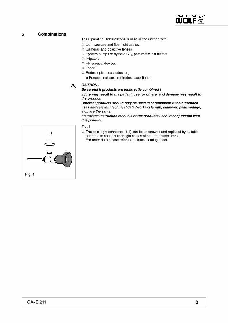
Fig. 1
Z The cold--light connector (1.1) can be unscrewed and replaced by suitableadaptors to connect fiber light cables of other manufacturers.For order data please refer to the latest catalog sheet.
Fig. 1
25
1.1

3 GA--E 211
6 Illustration
Fig. 2
2.9.12.9.2
2.9.4
2.9 2.9.3
1.1
1
#
3.33.2 2.12.52.4
2.6 2
2.2
2.7
2.3
2.8
3
3.1
4
#
1.2
6.1 Legend and identification
Item Designation Item Designation
1 PANOVIEW endoscope 2.9 Stopcock assembly
1.1 Cold--light connector 2.9.1 Stopcock plug
1.2 Fiber bundle diameter 2.9.2 Stopcock housing
2 OPTIFLOW single sheath 2.9.3 Luer fitting
2.1 Suction holes 2.9.4Passage identification on-- stopcock housing-- stopcock plug
2.2 Sheath tube 3 Ergonomic handle
2.3 Supply stopcock 3.1 Handle
2.4 Slide 3.2 Locking lever
2.5 Nose 3.3 Locking ring
2.6 Insertion stopcock (instrument port) 4 Rubber cap
2.7 Drain stopcock
2.8 Size of working channel in Fr. # Product number

4GA--E 211
Symbols Designation
Attention
REF Order number
Lot identification number
SN Serial number
Identification in conformity with Medical Devices Directive 93/42/EEC only valid if the product and/orpackaging are marked with this symbol. Products of category IIa and above, as well as sterileproducts or products with measuring function in category I, are additionally marked with the codenumber of the notified body (0124).

5 GA--E 211
7 Use
CAUTION !The products have only limited strength !Exerting excessive force will cause damage, impair the function and there-fore endanger the patient.Immediately before and after each use, check the products for damage,loose parts and completeness.Ensure that no missing instrument parts remain in the patient.Do not use products which are damaged, incomplete or have loose parts.
7.1 PreparationZ Check assembly: section 9.5Z Keep measuring system ready: section 7.2Z Carry out a check: sections 8 and 8.1Z Tighten the cold--light connector (1.1).
7.1.1 Inserting PANOVIEW endoscope (1) into OPTIFLOW single sheath (2)
Inserting
Fig. 3
Z Insert the PANOVIEW endoscope (1) axially into the OPTIFLOW single sheath(2), until the tab (2.4) clicks into place.' The groove (a) and the nose (2.5) must be aligned.
Remove
Fig. 4
Z Push down the tab (2.4), keep depressed, and remove PANOVIEW endoscope (1).
Fig. 3
2.4
2.5
1
a
Fig. 4
12.4
6GA--E 211
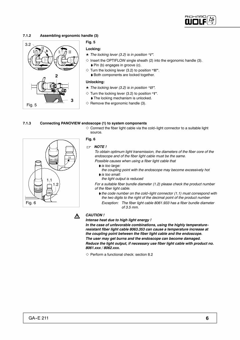
7.1.2 Assembling ergonomic handle (3)
Fig. 5
Locking:
L The locking lever (3.2) is in position “I”.Z Insert the OPTIFLOW single sheath (2) into the ergonomic handle (3).'Pin (b) engages in groove (c).
Z Turn the locking lever (3.2) to position “II”.'Both components are locked together.
Unlocking:
L The locking lever (3.2) is in position “II”.Z Turn the locking lever (3.2) to position “I”.' The locking mechanism is unlocked.
Z Remove the ergonomic handle (3).
7.1.3 Connecting PANOVIEW endoscope (1) to system componentsZ Connect the fiber light cable via the cold--light connector to a suitable light
source.
Fig. 6
. NOTE !To obtain optimum light transmission, the diameters of the fiber core of theendoscope and of the fiber light cable must be the same.Possible causes when using a fiber light cable that' is too large:the coupling point with the endoscope may become excessively hot
' is too small:the light output is reduced
For a suitable fiber bundle diameter (1.2) please check the product numberof the fiber light cable.' the code number on the cold--light connector (1.1) must correspond withthe two digits to the right of the decimal point of the product numberException: The fiber light cable 8061.933 has a fiber bundle diameter
of 3.5 mm.
CAUTION !Intense heat due to high light energy !In the case of unfavorable combinations, using the highly temperature-resistant fiber light cable 8063.353 can cause a temperature increase atthe coupling point between the fiber light cable and the endoscope.The user may get burns and the endoscope can become damaged.Reduce the light output, if necessary use fiber light cable with product no.8061.xxx / 8062.xxx.
Z Perform a functional check: section 8.2
3.2c b
2
3
IIIII
I
Fig. 5
25
25
Fig. 6
1.21.1
7 GA--E 211
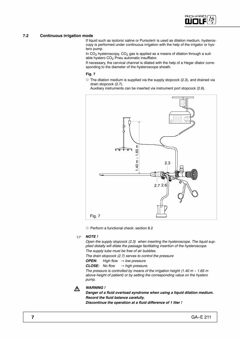
7.2 Continuous irrigation modeIf liquid such as isotonic saline or Purisole® is used as dilation medium, hysteros-copy is performed under continuous irrigation with the help of the irrigator or hys-tero pump.In CO2 hysteroscopy, CO2 gas is applied as a means of dilation through a suit-able hystero CO2 Pneu automatic insufflator.If necessary, the cervical channel is dilated with the help of a Hegar dilator corre-sponding to the diameter of the hysteroscope sheath.
Fig. 7
Z The dilation medium is supplied via the supply stopcock (2.3), and drained viadrain stopcock (2.7).Auxiliary instruments can be inserted via instrument port stopcock (2.6).
Fig. 7
2.3
2.62.7
1.40
m--1.65
m
Z Perform a functional check: section 8.2
. NOTE !Open the supply stopcock (2.3) when inserting the hysteroscope. The liquid sup-plied distally will dilate the passage facilitating insertion of the hysteroscope.The supply tube must be free of air bubbles.The drain stopcock (2.7) serves to control the pressureOPEN: High flow → low pressureCLOSE: No flow → high pressure.The pressure is controlled by means of the irrigation height (1.40 m -- 1.65 mabove height of patient) or by setting the corresponding value on the hysteropump.
WARNING !Danger of a fluid overload syndrome when using a liquid dilation medium.Record the fluid balance carefully.Discontinue the operation at a fluid difference of 1 liter !

8GA--E 211
7.3 CO2 modeZ The dilation medium is supplied via supply stopcock (2.3), the insertion stop-
cock (instrument port) (2.6) and the drain stopcock (2.7) are closed.
Fig. 8
2.3
2.62.7Fig. 8
Z Perform a functional check: section 8.2
. NOTE !Open the supply stopcock (2.3) supply when inserting the hysteroscope. The CO2gas supplied from the distal end of the hysteroscope will dilate the passage facilitat-ing insertion of the hysteroscope.The pressure is controlled by the Hystero CO2 Pneu automatic insufflator.
WARNING !Air in the supply system !Danger of embolism !Before use, purge the supply system for one minute at a flow of 100ml / min.
9 GA--E 211
7.4 Additional notes and instructions for use
7.4.1 Light
. IMPORTANT !Use only products with type BF or CF applied parts in conjunction with the Operat-ing Hysteroscope.
WARNING !Heat may be generated due to high light energy !Danger of unintentional tissue damage' due to insufficient distance between the light exit area and tissue' due to soiling/contamination in the light exit area' if high-performance light source are used.
Do not touch the light exit area and avoid direct contact with the tissue.Remove any soiling/contamination.
WARNING !Fire hazard !Do not place the light exit area against heat-sensitive flammable surfaces(dark drapes etc.) as this can lead to excessively high temperatures or evenignition.Lay down the Operating Hysteroscope in a safe place.Switch off the light source if the Operating Hysteroscope will not be usedfor a period of time.
CAUTION !Danger of burns !As a result of the high level of light energy at the cold- light connector, theconnector is extremely hot when it is disconnected from the light source.Burns may result from unintentional contact with the connector.Do not touch the cold- light connector before it has cooled down.
7.4.2 Current
WARNING !Danger of electrical shock !Patient leakage currents can add up if endoscopes are combined with elec-trically powered endoscopic accessories.Make sure that the combinations do not exceed the permissible patientleakage currents.
7.4.3 Image quality
CAUTION !Increased danger potential if image is blurred !Patient may be injured.Stop operation for safety reasons if image is blurred.Check image quality of endoscope before use (section 8.2.2).
7.4.4 Irrigation fluid
CAUTION !Irrigation fluids can be electrically conductive !The user must choose a low-conductivity irrigation fluid suitable for theapplication.Do not use NaCl (saline) for HF applications.

10GA--E 211
7.5 HF applicationMake sure you observe the “Instructions and notes on HF applications”, orderno.: GA--S 002 as well as the HF device manufacturer’s instructions.
WARNING !Danger of injury if HF instrument is not visible through the scope !Inadvertent tissue damage as well as damage to the distal end of the Oper-ating Hysteroscope and the instrument parts is possible.HF instruments should therefore be used only within the scope of theirspecifications as to electric strength, mode of operation.Activate HF instruments only if the live high- frequency part is fully visiblethrough the Operating Hysteroscope and contacts with the area to betreated.
WARNING !
HF arcing !Danger of injury due to incorrect HF application and insufficient distancebetween live HF instruments and other conductive parts.Live high- frequency parts of HF instruments must be kept at a safe distanceof at least 10mm from the distal end of the OPTIFLOW single sheath (2)(Fig. 9) when they are activated.
CAUTION !Take care when selecting the HF output power. Do not use excessive HFoutput power !The patient may be injured and the product may become damaged.The power must be set in accordance with the experience and / or trainingof the surgeon with regard to the respective indication.
7.6 Laser applicationWhen using lasers, make sure you observe the laser device manufacturer’s in-structions as well as the general instructions on the use of lasers.Wear the required personal protection gear.
CAUTION !Do not work outside the scope’s field of view !Inadvertent tissue damage as well as damage to the distal end of the Oper-ating Hysteroscope and instrument parts can occur.
Activate the laser only after' the tip of the laser fiber has become fully visible through the OperatingHysteroscope and
' the area to be treated makes contact by means of the pilot beam.
CAUTION !High temperatures due to highly coherent laser beam !The heat generated by the laser beam reduces the strength of instrumentparts.Do not direct the laser beam at instrument parts, in particular not at plasticparts.Keep a safe distance.
CAUTION !Danger of eye injury when using lasers without filter attachment !Use a suitable filter attachment on the endoscope eyepiece.
Fig. 92
10mm
11 GA--E 211
7.7 Inserting auxiliary instruments
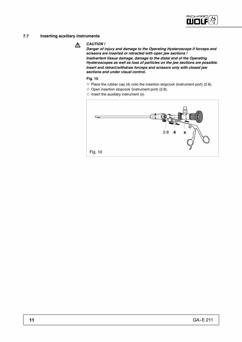
CAUTION !Danger of injury and damage to the Operating Hysteroscope if forceps andscissors are inserted or retracted with open jaw sections !Inadvertent tissue damage, damage to the distal end of the OperatingHysteroscopes as well as loss of particles on the jaw sections are possible.Insert and retract/withdraw forceps and scissors only with closed jawsections and under visual control.
Fig. 10
Z Place the rubber cap (4) onto the insertion stopcock (instrument port) (2.6).Z Open insertion stopcock (instrument port) (2.6).Z Insert the auxiliary instrument (x).
Fig. 10
2.6 x4

12GA--E 211
8 Checks
CAUTION !Be careful if products are damaged or incomplete !Injury may result to the patient, user or others.Run through the checks before and after each use.Do not use products which are damaged or incomplete or have loose parts.Return damaged products together with loose parts for repair.Do not attempt to do any repairs yourself.
8.1 Visual checkZ Check the instruments, in particular their distal areas, and accessories for:' damage' sharp edges' loose or missing parts' rough surfaces.
Z Any lettering, labeling or identification necessary for the safe intended usemust be legible.'Missing or illegible lettering, labeling or identification which may lead towrong handling and reprocessing must be restored.
Fig. 11
Z Check that the distal lateral suction openings (2.1) in the sheath tube (2.2) arenot clogged.
Fig. 12
Z Replace damaged or brittle rubber caps (4).
8.2 Functional checkZ Check the individual components for compatibility.Z Check that the connections are securely locked.Z Check that the individual instruments can be assembled and locked together
easily. Replace the instruments if the connection' although locked is not secure' cannot be locked or is difficult to lock.
Z Check the supply (2.3), drain (2.7) and instrument port stopcock (2.6) for easyoperation.
Z Check that the auxiliary instruments can be inserted easily through instrumentport stopcock (2.6).
Z Rinse out the supply stopcock(2.3) and drain stopcock (2.7) using the irrigator.'On the distal side the dilation medium must form a spray jet.' in the case of CO2 gas no pressure must build up.
Z Check the entire system for leak--tightness and patency (free passage).
Fig. 11
2.1 2.2
Fig. 12
4
13 GA--E 211
8.2.1 Stopcock plug (2.9.1)
Fig. 13
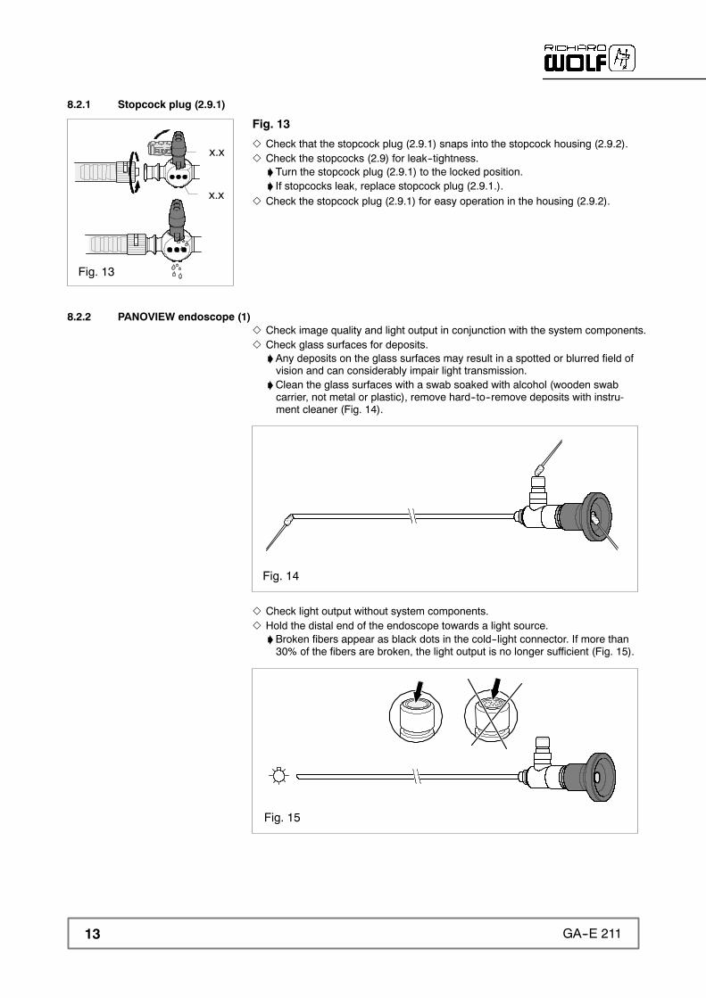
Z Check that the stopcock plug (2.9.1) snaps into the stopcock housing (2.9.2).Z Check the stopcocks (2.9) for leak--tightness.' Turn the stopcock plug (2.9.1) to the locked position.' If stopcocks leak, replace stopcock plug (2.9.1.).
Z Check the stopcock plug (2.9.1) for easy operation in the housing (2.9.2).
8.2.2 PANOVIEW endoscope (1)Z Check image quality and light output in conjunction with the system components.Z Check glass surfaces for deposits.'Any deposits on the glass surfaces may result in a spotted or blurred field ofvision and can considerably impair light transmission.
'Clean the glass surfaces with a swab soaked with alcohol (wooden swabcarrier, not metal or plastic), remove hard--to--remove deposits with instru-ment cleaner (Fig. 14).
Fig. 14
Z Check light output without system components.Z Hold the distal end of the endoscope towards a light source.'Broken fibers appear as black dots in the cold--light connector. If more than30% of the fibers are broken, the light output is no longer sufficient (Fig. 15).
Fig. 15
x.x
x.x
Fig. 13
14GA--E 211
9 Reprocessing and maintenance
9.1 Disassembly before cleaningZ Remove auxiliary instrument.Z Remove all connections between the Operating Hysteroscopes and the system
components.Z Remove all parts used:'PANOVIEW endoscope (1): section 7.1.1'Cold--light connector (1.1)'Ergonomic handle (3): section 7.1.2'Rubber cap (4)
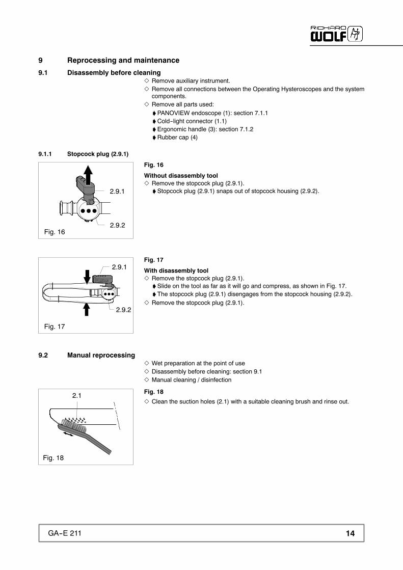
9.1.1 Stopcock plug (2.9.1)
Fig. 16
Without disassembly toolZ Remove the stopcock plug (2.9.1).'Stopcock plug (2.9.1) snaps out of stopcock housing (2.9.2).
Fig. 17
With disassembly toolZ Remove the stopcock plug (2.9.1).'Slide on the tool as far as it will go and compress, as shown in Fig. 17.' The stopcock plug (2.9.1) disengages from the stopcock housing (2.9.2).
Z Remove the stopcock plug (2.9.1).
9.2 Manual reprocessingZ Wet preparation at the point of useZ Disassembly before cleaning: section 9.1Z Manual cleaning / disinfection
Fig. 18
Z Clean the suction holes (2.1) with a suitable cleaning brush and rinse out.
2.9.2
2.9.1
Fig. 16
2.9.2
2.9.1
Fig. 17
Fig. 18
2.1

15 GA--E 211
9.3 Machine reprocessingZ Dry preparation at the point of useZ Disassembly before cleaning: section 9.1Z Machine cleaning / disinfection'Manual precleaning of the suction holes (2.1): section 9.2
. NOTE !For automatic (machine) reprocessing of the stopcock plugs (2.9.1) use a smallparts sieve.
9.4 ChecksZ Perform a visual check: sections 8 and 8.1
9.5 Assembly before sterilization
. NOTE !Before sterilization screw on screw connections only loosely' to allow adequate flow of the sterilization medium' to avoid stress cracks
Tighten all screw connections before use.
Z Screw on the cold--light connector (1.1) loosely only 1--2 turns.
9.5.1 Stopcock plug (2.9.1)
Fig. 19
Z Insert the stopcock plug (2.9.1) into the stopcock housing (2.9.2).'You can feel and hear the stopcock plug (2.9.1) engage in the housing.
Z Open the stopcock plug (2.9.1).
9.6 Sterilization
9.6.1 Steam sterilizationZ Steam sterilization at 132° C (270° F) using a Pre--Vac cycle at an exposure
time of 4 minutes with a 20 minute dry time.
9.6.2 Gas sterilizationZ Gas sterilization using ethylene oxide (EtO).
9.6.3 High--Level--DisinfectionZ CIDEX OPA Solution provides a high--level disinfection and is compatible with
all Richard Wolf products.' Follow the immersion time and concentration specified by the disinfectantmanufacturer.
Z GLUTARALDEHYDE Solution allows a high--level disinfection.' Follow the immersion time and concentration specified by the disinfectantmanufacturer.
CONTRAINDICATIONS
CAUTION !CIDEX OPA Solution should not be utilized to process instrumentation for patientswith known sensitivity to CIDEX OPA Solution or any of its components.
2.9.1
2.9.2
Fig. 19

16GA--E 211
10 Technical data and order dataFor additional information on the reprocessing, see Manual GA--J020 “Reproces-sing of RICHARD WOLF Heat Stable Instruments”.
Item Illustration Product no. Designation, technical data
2 8974351OPTIFLOW single sheathTotal length = 318 mm; working length = 219 mm;outside dia. = 5.5 mm; working channel = 5 Fr.
11 Spare parts and accessories
Item Illustration Product no. Designation, technical data
1
8974.402
PANOVIEW endoscopeTotal length = 371 mm; working length = 318 mm;outside dia. = 2.7 mm; viewing direction = 30°;image angle = 80°
1
8974.412
PANOVIEW endoscopeTotal length = 373 mm; working length = 317 mm;outside dia. = 2.7 mm; viewing direction = 12°;image angle = 66°
3 8986.251 Ergonomic handle
Forceps and scissors -- HySafe small modular system
-- 8642.6002Biopsy forceps (spoon)Total length = 495 mm; working length = 340 mm; 5 Fr.
-- 8642.6502Grasping forceps, pike--mouth shapedTotal length = 495 mm; working length = 340 mm; 5 Fr.
-- 8642.6312Biopsy punchTotal length = 495 mm; working length = 340 mm; 5 Fr.
-- 8642.6812MicroscissorsTotal length = 495 mm; working length = 340 mm; 5 Fr.
Rigid forceps and scissors
-- 8642.60Biopsie forceps, rigidTotal length = 443 mm; working length = 340 mm; 5 Fr.
-- 8642.65Grasping forceps, rigidTotal length = 450 mm; working length = 340 mm; 5 Fr.
-- 8642.631Biopsy punch, rigidTotal length = 470 mm; working length = 355 mm; 5 Fr.
-- 8642.681Scissors, rigidTotal length = 500 mm; working length = 355 mm; 5 Fr.

17 GA--E 211
Item Illustration Product no. Designation, technical data
4
88.005RERubber cap “RIWO”red for instruments smaller than 3 Fr.packaging unit = 12/pkg.
4
88.01RERubber cap “RIWO”rot for instruments up to 7 Fr.packaging unit = 12/pkg.
-- 886.00 Luer lock tube connector
2.9.1 896.0001Replacement stopcock plugs, 1.8 mm / 2.5 mm passageidentification: 2 pegspackaging unit = 5/pkg.
2.9.1 896.0002Replacement stopcock plugs, 3.0 mm passageidentification: 3 pegspackaging unit = 5/pkg.
-- 38310.0001 Disassembly tool
BL
40605Cleaning brush for optic channel, disposable, 10/pkgTotal length TL = 600 mm; Brush dia. ∅ D = 5 mm; Brush length BL = 75 mm
--
BL
GLD 7990001
Cleaning brush for inflow / outflow channel, disposable, 10/pkgTotal length TL = 1200 mm; Brush dia. ∅ D = 2 mm; Brush length BL = 15 mmGL
40604Cleaning brush for working channel, disposable, 10/pkgTotal length TL = 400 mm; Brush dia. ∅ D = 2 mm; Brush length BL = 95 mm
-- 40999012Cleaning brush for external surfaces, disposable, 3/pkgTotal length 147 mm; Brush length 42 mm
The products can be combined as required provided the relevant technical data and intended uses are ob-served. For the general overview please refer to the latest catalog sheets and brochures, or contact RichardWolf or your Richard Wolf representative.
12 Operating, storage, transport and shipping conditions
Operating conditions +10°C to +40°C , 30% to 75% rel. humidity,atmospheric pressure 700 hPa to 1060 hPa
Storage, transport and shipping conditions -- 20°C to +60°C , 10% to 90% rel. humidity,atmospheric pressure 700 hPa to 1060 hPa
. NOTE !To prevent damage during transport or shipment of the products we recommendusing the original packaging material.
12.1 Disposal of product, packaging material and accessoriesObserve the regulations and laws valid in your country for disposal.' For further information please contact the manufacturer.
18GA--E 211
13 Literature. IMPORTANT !
As we cannot provide a comprehensive bibliography we would ask users to keepthemselves informed of all new developments in this field.
Z A multi--centre collaborative study into the treatment of menorrhagia by Nd:YAG laser ablation of the endometriumGarry R, Erian J, Grochmal SA: Br J Obstet Gynaecology 98: 357--362, 1991.
Z Carbon Dioxide Hysteroscopy: Principles and Physiology. In Hysteroscopy,Principles and PracticeGallinat A: Edited by AM Siegler, HJ Lindemann. Philadelphia, J.B. Lippincott, 1984,pp 45--47.
Z Comparison of CO2 and Continuous--Flow Technique for Office Hysteroscopy.In Hysteroscopy UpdateGoldfarb HA: Edited by JM Phillips, RB Hunt, FD Loffer. Santa Fe Springs, AAGLPublications Corporation, 1997, pp 25--27.
Z Control of intrauterine fluid pressure during operative hysteroscopyShirk GJ, Gimpelson RJ: J Am Assoc Gynecol Laparosc 1: 229--133, 1994.
Z Diagnostic and therapeutic hysteroscopy in the management of abnormaluterine bleedingMotashaw ND, Dave S: J Reprod Med 35:616--620, 1993.
Z Die hysteroskopische Resektion submukoser MyomeHucke J, Campo RL, Bruyne de F, et al: Geburtshilfe Frauenheilkd 52: 214--218, 1992.
Z Distension Media and Fluid Systems. In Endoscopic Surgery for Gynae--cologists.Garry R: Edited by C Sutton and M Diamond. London, W.B. Saunders, 1993 pp282--290.
Z Distention Media. In Lasers in Gynecology.Gallinat A: Edited by G Bastert and D Wallwiener. Berlin, Springer--Verlag, 1992,pp 235--237.
Z Endometrial laser ablation. In Endometrial AblationGarry R: Edited by BV Lewis, AL Magos. New York, Churchill-- Livingstone, 1993,pp 67--81.
Z Experience with the first 250 endometrial resections for menorr hagiaMagos AL, Baumann R, Lockwood GM, et al: Lancet 337 (4): 1074--1078, 1991.
Z Fibroids. In Endometrial AblationWamsteker K, de Blok S, Gallinat A, et al: Edited by BV Lewis, AL Magos. New York,Churchill Livingstone, 1993, pp 171--181.
Z HF Electrosurgery Versus Laser in Hysteroscopy. In Lasers in GynecologyWamsteker K, De Blok S: Edited by G Bastert and D Wallwiener. Berlin, Springer--Verlag, 1992, pp 211--213.
Z Hysteroscopic surgery with the Nd: YAG laserDonnez J, Nisolle M, Gillerot S, et al: Gynaecol Endose 2 (3) 121--129, 1993.
Z HysteroscopyTaylor PJ, Hamou JF: J Reprod Med 28: 359--389, 1984.
Z Laser photovaporization of endometrium for the treatment of menorrhagiaGoldrath MH, Fuller TA, Segal S: Am J Obstet Gynecol 140: 14, 1981
Z Laser Technique versus Electrosurgery in the Hysteroscopic Treatment ofSubmucous Fibroids. In Hysteroscopy UpdateGallinat A, Lueken RP: Edited by JM Phillips, RB Hunt, FD Loffer. Santa Fe Springs,AAGL Publications Corporation, 1997, pp 65--66.
19 GA--E 211
Z Operative HysteroskopieHucke J: Gynäkologie 1997 30:392--409
Z Removal of Submucous Myomata with Intramural Parts. In Hysteroscopy UpdateGallinat A, Lueken RP: Edited by JM Phillips, RB Hunt, FD Loffer. Santa FeSprings, AAGL Publications Corporation, 1997, p 85.
Z Resection of intrauterine fibroids. In Endometrial AblationWamsteker K, de Blok S: Edited by BV Lewis, AL Magos. New York, ChurchillLivingstone, 1993, pp 161--170.
Z Resectoscopic myomectomyCorson SL, Books PG: Fertil Steril 55: 1041, 1991.
Z The Aplication of the Nd: YAG Laser in CO2 Hysteroscopy. In Lasers inGynecologyLueken RP, Gallinat A, Möller CP: Edited by G Bastert and D Wallwiener. Berlin,Springer--Verlag, 1992, pp 203--210.
Z Trans--cervical Resection of the Endometrium (TCRE). In Endoscopic Surgeryfor Gynaecologists.Broadbent JAM, Magos AL: Edited by C Sutton and M Diamond, London, W.B.Saunders 1993, pp 294--306.
Z Treatment of Irregular Menstrual Bleeding by Hysteroscopic Resection ofSubmucous Myomas and Polyps. In Hysteroscopy, Principles and PracticeDcCherney AH: Edited by AM Siegler, HJ Lindemann. Philadelphia, J.B. Lippincott,1984, pp 138--139.
Z YAG Laser Ablation of the Endometrium. In Endoscopic Surgery for Gynae-colgists.Goldrath MH, Garry R: Nd: Edited by C Sutton and M Diamond. London, W.B.Saunders 1993, pp 317--326.

20GA--E 211
14 Warranty and Customer Service
RichardWolf guarantees our instruments to be free fromany defects inmaterials andworkmanshipundernormal use and service for one year. Richard Wolf general terms and conditions may be found on theback of our invoice.
Parts delivered separately by RichardWolf are subject to all of the samegeneral terms and conditions forour products, including the limitations of warranty and liability.
All products should be returned to Richard Wolf for any necessary or desired repair or part replacement.No product repair or part replacement should be done other than by Richard Wolf unless the care andinstruction manual or other written information indicates that repair or part replacement is authorized. Ifauthorized, partsmust be replaced only by parts supplied or specified byRichardWolf,and product repairand part replacement must be done in strict conformance with Richard Wolf specifications andinstructions for repair and part replacement, including post replacement testing and recalibration. Failureto follow this requirement in any way can be dangerous to you, your personnel and your patients andvoids the warranty for the product repaired or the product in which the part was replaced and if the partwas supplied by Richard Wolf, for that part.
Delivery by Richard Wolf of technical documents such as circuit or other design diagrams does notconstitute authorization for product repair or part replacement. Richard Wolf instruments and otherproducts should never be modified or altered under any circumstances.
Contact RichardWolf if you have any question (1) whether replacement of a part or a repair is authorizedbyRichardWolf, or (2)whether you have complete instructions and specifications for part replacement orrepair.
These instructions do not attempt to cover all details or variations in equipment, nor to provide for everypossible contingency to bemet in connection with installation, operation, ormaintenance. Should furtherinformation be required or should problems arise which are not covered sufficiently for the purchaser’spurpose, the matter should be referred to Richard Wolf Medical Instruments Corporation.
Our national sales and service offices, as well as ourmanufacturing facility, are located in Illinois. Trainedmanufacturer’s representatives are located throughout the U.S. to serve you. For any questionsregarding these instruments, or to place an order, contact Richard Wolf customer service department at847--913--1113 or 800--323--WOLF (9653).
INSTRUMENT ORDERING POLICYRichard Wolf reserves the right to make substitutions, if necessary, without prior notice.
REPAIR POLICYDefective merchandise will be repaired or replaced at no charge to the customer, provided the customerdelivers such defective merchandise prepaid. Any repairs, maintenance or servicing of Richard Wolfmerchandise by anyone other than a factory authorized representative will render our warranty null andvoid.
REPAIR SHIPMENTSWhen returning your instrument for repair, we suggest that you prevent shipping damage to theinstrument by reusing the box that it was originally shipped in. Richard Wolf also recommends that theinstrument be insured for an amount to cover the cost of replacement.
IMPORTANTFor general safety and health reasons, Richard Wolf requires that you clean and sterilize all instrumentsbefore returning them for repair. If instruments are received in an unsanitary condition, Richard Wolf willclean and sterilize each instrument and add a $ 92.00 cleaning charge for each instrument requiringcleaning.


