27
Sybex CCNA 640-802 Chapter 3: Introduction to TCP/IP Instructor & Todd Lammle
| Date post: | 30-Dec-2015 |
| Category: |
Documents |
| Upload: | fleur-castaneda |
| View: | 53 times |
| Download: | 2 times |

Sybex CCNA 640-802Chapter 3: Introduction to TCP/IP
Instructor & Todd Lammle

Chapter 2 Objectives
• The CCNA Topics Covered in this chapter include:
• TCP/IP and the DoD Model– Process/Application Layer– Host-to-Host Layer– Internet Layer– Network Access
• IP Addressing– Class A– Class B– Class C– Private Addressing
2

TCP/IP and the DoD ModelThe figure shows a comparison of the DoD model and the OSI reference model. As you can see, the two are similar in concept, but each has a different number of layers with different names.
3

The TCP/IP Protocol SuiteThe DoD and OSI models are alike in design and
concept and have similar functions in similar layers.
4

Process/Application Layer
This section describes different applications and services typically used in IP networks. Some of the protocols and applications are
discussed are:
– Telnet
– FTP
– TFTP
– NFS
– SMTP
– LPD
– X Window
– SNMP
– DNS
– DHCP/BootP5

DHCP
6

Host to Host Layer
The main purpose of the Host-to-Host layer is to shield the upper-layer applications from the complexities of the network.
This layer says to the upper layer, “Just give me your data stream, with any instructions, and I’ll begin the process of getting your information ready to send.”
The following sections describe the two protocols at this layer:– Transmission Control Protocol (TCP)– User Datagram Protocol (UDP)
7

TCPThe figure shows the different fields
within the TCP header.
8

UDPThis figure clearly illustrates UDP’s markedly low
overhead as compared to TCP’s hungry usage.
9

Key concepts of Host to Host Protocols
TCP UDP
Sequenced Unsequenced
Reliable Unreliable
Connection-oriented Connectionless
Virtual circuit Low overhead
Acknowledgments No acknowledgment
Windowing flow control No windowing or flow control
10

Port NumbersPort number examples for TCP and UDP
11

Key Protocols and Port Numbers
12
TCP UDPTelnet 23 SNMP 161SMTP 25 TFTP 69HTTP 80 DNS 53FTP 21DNS 53HTTPS 443
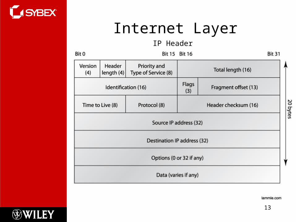
Internet Layer
13
IP Header

Internet Layer
14
Protocol Field in IP Header

Internet Layer
15
Protocol Field in IP Header
Protocol Protocol Number ICMP 1 IP in IP (tunneling) 4 IGRP 9 EIGRP 88 OSPF 89
IPv6 41 GRE 47 Layer 2 tunnel (L2TP) 115

Internet Layer
16
ICMP
Internet Control Message Protocol (ICMP) works at the Network layer and is used by IP for many different services.
•ICMP is a management protocol and messaging service provider for IP. •Its messages are carried as IP datagrams.
ICMP packets have the following characteristics:
• They can provide hosts with information about network problems.• They are encapsulated within IP datagrams.

Internet Layer
17
ICMPE0 of LAB_B goes down. What happens?

Internet Layer
18
ICMP In action

Internet Layer
19
ARP
ARP resolves IP addresses to Ethernet (MAC) addresses.
Internet Layer
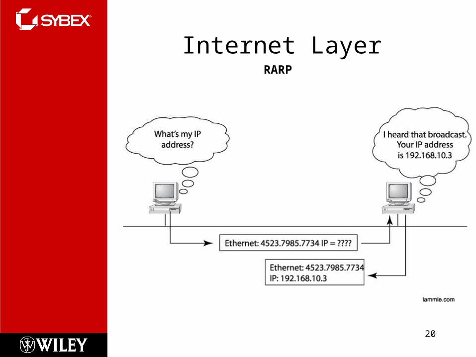
20
RARP

IP Addressing
21
An IP address is a numeric identifier assigned to each machine on an IP network.
It designates the specific location of a device on the network.
IP addressing was designed to allow hosts on one network to communicate with a host on a different network regardless of the type of LANs the hosts are participating in.

IP Terminology
22
BIT: A bit is one digit, either a 1 or a 0.
BYTE: A byte is 7 or 8 bits, depending on whether parity is used. For the rest of this chapter, always assume a byte is 8 bits.
OCTET: An octet, made up of 8 bits, is just an ordinary 8-bit binary number. In this chapter, the terms byte and octet are completely interchangeable.
Network address: This is the designation used in routing to send packets to a remote network—for example, 10.0.0.0, 172.16.0.0, and 192.168.10.0.
Broadcast address: The address used by applications and hosts to send information to all nodes on a network is called the broadcast address.

Network Addressing
23
Subdividing an IP address into a network and node address is determined by the class designation of one’s network. This figure summarizes the three classes of networks

Reserved Addressing
24
Address Function Network address of all 0s Interpreted to mean “this network or
segment.” Network address of all 1s Interpreted to mean “all networks.” Network 127.0.0.1 Reserved for loopback tests. Node address of all 0s Interpreted to mean “network address” or
any host on specified network. Node address of all 1s Interpreted to mean “all nodes” on the
specified networkEntire IP address set to all 0s Used by Cisco routers to designate the
default route. Could also mean “any network.”
Entire IP address set to all 1s (same as Broadcast to all nodes on the current network; 255.255.255.255) sometimes called an “all 1s broadcast” or limited broadcast

Private Addressing
25
Address Class Reserved Address Space Class A 10.0.0.0 through 10.255.255.255 Class B 172.16.0.0 through 172.31.255.255 Class C 192.168.0.0 through 192.168.255.255

IPv4 Address Types
26
• Layer 2 broadcasts• Broadcasts (layer 3)• Unicast • Multicast

Written Labs and Review Questions
– Open your books and go through all the written labs and the review questions.
– Review the answers in class.
27


