73
Instrument Air Systems A Guide for Power Plant Maintenance Personnel NNA- r=(r2i

Instrument Air Systems A Guide for Power Plant Maintenance
Personnel
NNA-
r=(r2i

R.E P 0 R T SUMMARYNuclear plant operations and maintenance / Maintenance practices
TOPICS Compressed air Instrument air Maintenance
AUDIENCE
BACKGROUND
OBJECTIVE
APPROACH
Maintainability Air filters Air dryers
Maintenance engineers and planners / Education and training managers
Instrument Air Systems A Guide for Power Plant Maintenance Personnel
Though the instrument air system in a nuclear power plant is
designated as a non-safety-related system, its failure can result in
power reduction or even reactor scrams. Most problems with in
strument air systems can be resolved by proper understanding
and maintenance of the system. This guide provides insights into
possible system difficulties and suggests steps to take to avoid them.
A recent NRC generic letter 88-14 and an Institute of Nuclear Power Opera
tions Significant Operating Experience Report (SOER) 88-1 raise serious
questions regarding the failure of instrument air systems to operate consis
tently within their design parameters. Problems were traced to inadequate
system maintenance. This guide responds with a comprehensive source of
information specific to instrument air system maintenance.
To develop a maintenance guide for instrument air systems in nuclear power 'plants.
EPRI's Nuclear Maintenance Applications Center (NMAC) reviewed a sig
nificant amount of data on compressors and compressed air, most of which
did not apply to the power generation industry. From this data, NMAC dis
tilled the information applicable to the operation and maintenance of instru
ment air systems in power plants. Following discussions with equipment
suppliers and utility personnel responsible for the maintenance of instru
ment air systems, they developed the guide and sent it out for a compre
hensive review.
RESULTS This guide
- Addresses instrument air maintenance on a system basis, with a focus on
problems caused by various contaminants, leaks, and component failures
• Provides a description of periodic maintenance activities on various sys
tem components
• Outlines detailed recommendations concerning air filters and dryer desic
cants, with a discussion of cost-effectiveness
EPRI NP-7079s Electric Power Research Institute
SUBJECTS
Electric Power Research InstituteEPRI NP-7079s

EPRI PERSPECTIVE The instrument air system is an important support system in any power generation plant. Recently, regulatory bodies and industry organizations have expressed concern that insufficient emphasis is placed on the maintenance of instrument air systems. This guide should assist utilities in identifying system problems, thus enabling them to maintain required industry safety standards. EPRI's Nuclear Safety Analysis Center (NSAC) is continuing efforts in this area, with instrument air studies that focus on maintaining system operability (reports NSAC-128 and NSAC-137).
PROJECT RP2814-29 EPRI Project Manager: Biswanath (Vic) Varma Nuclear Maintenance Applications Center / Nuclear Power Division Contractor: BCP Technical Services, Inc.
For further information on EPRI research programs, call EPRI Technical Information Specialists (415) 855-2411.

Instrument Air Systems A Guide for Power Plant Maintenance Personnel
N P-7079 Research Project 2814-29
Final Report, December 1990
Prepared by
V. Varma NMAC
BCP TECHNICAL SERVICES, INC. 3000 General DeGaulle, Suite 210
New Orleans, Louisiana 70114
Principal Investigators S. Preckwinkle
K. Webber
Prepared for
Nuclear Maintenance Applications Center
Operated by
Electric Power Research Institute 3412 Hillview Avenue
Palo Alto, California 94304
EPRI Project Manager
V. Varma
Nuclear Power Division

ORDERING INFORMATION
Requests for copies of this report should be directed to Research Reports Center (RRC), Box 50490, Palo Alto, CA 94303, (415) 965-4081. There is no charge for reports requested by EPRI member utilities and affiliates, U.S. utility associations, U.S. government agencies (federal, state, and local), media, and foreign organizations with which EPRI has an information exchange agreement. On request, RRC will send a catalog of EPRI reports.
Price: $9200.00
IMPORTANT NOTICE REGARDING THIS DOCUMENT
Use of this document and its contents is completely voluntary. It is not intended for regulatory or enforcement purposes. It is offered for consideration and use by members of NMAC/EPRI. Use of this document and its contents by anyone other than those for which it is intended is not authorized. This document is based on consensus of the writers, reviewers and contributors. There may be other techniques or means of performing the work or activities described here. Users are encouraged to contribute items for inclusion in future revisions. All contributions will be considered.
Electric Power Research Institute and EPRI are registered service marks of Electric Power Research Institute, Inc.
Copyright © 1990 Electric Power Research Institute, Inc All rights reserved.
NOTICE This report was prepared by the organization(s) named below as an account of work sponsored in part by the Electric Power Research Institute, Inc (EPRI). Neither EPRI, members of EPRI, the organization(s) named below, nor any person acting on behalf of any of them: (a) makes any warranty, express or implied, with respect to the use of any information, apparatus, method, or process disclosed in this report or that such use may not infringe privately owned rights; or (b) assumes any liabilities with respect to the use of, or for damages resulting from the use of, any information, apparatus, method, or process disclosed in this report.
Prepared by BCP Technical Services, Inc. New Orleans, Louisiana

.Instrument Air Guide iii
PREFACE
Instrument Air System maintenance problems have recently drawn wide attention from the Nuclear Power Industry and the regulatory agencies. This reference manual is designed to help power plant maintenance personnel understand, evaluate and resolve instrument air system problems. This can also be used as training guide for maintenance personnel or system engineers. Manual describes in detail the instrument air system, its components, common problems and their causes, and how to maintain the system to meet the quality requirements of a nuclear power plant. Manual only covers the type of equipment and conditions encountered in a power generation facility for the supply of Instrument Air System. Therefore, this is not a complete handbook on compressors or compressed air system. Also, this manual is not intended to be a substitute for existing codes and standards. Although, some information has been given in this manual so that maintenance personnel can evaluate the system capacity, system design or modification is beyond the scope of this work.
Equipment vendor manuals provide details for repair of individual equipment. Therefore, we have made no attempt to cover such detail in this booklet.

Instrument Air Guide V
ACKNOWLEDGMENTS
This guide was prepared for the Nuclear Maintenance Applications Center (NMAC), under Electric Power Research Institute project number 2814-29. In any document of this scope, numerous individuals and organizations provide extensive assistance and information to make the publication possible. We would like to acknowledge the assistance provided by James McCormick, Manager, Ingersoll-Rand Company and Phil Martinez, Manager, Sullair Corporation in granting us permission to reproduce illustrations and other information from their equipment manuals.
NMAC and BCP particularly recognizes the following individuals for their valuable contributions through thorough reviews and comments. Time and attention provided by each is gratefully appreciated:
Joe Marsala
Ray Romito
Don Gabriel
Lee Hentz
Richard Hecht
Jim Scarola
Harold Wilson
Carl Patrickson
Brian Curry
Julie Panayotides
George Belchick
James Christie
Mark Haynie
Russ Kaufman
George Allen
Baltimore Gas and Electric Co.
Commonwealth Edison Co.
Duke Power Co.
Duke Power Co.
Duquesne light Co.
Florida Power & Light Co.
GPU Nuclear Corp.
New York Power Authority
Philadelphia Electric Co.
Philadelphia Electric Co.
Union Electric Co.
Yankee Atomic Electric Co.
C.M. Kemp Co.
Sullair Corp.
Kali-Chemie Corp.

Instrument Air Guide vii
CONTENTS
1.0 Introduction......... .... ... .... .... ... ........ 1
. . . . . . . . . .32.0 Basic System Description ........
3.0 Components .................... Air Intake ..................... Air Intake Filters ................ Compressor ......... . ..... Lubrication and Lubrication Systems Lubricants ..... Intercoolers and Aftercoolers ....... Moisture Separators .............. Receivers ..................... Prefilters and Afterfilters ............ Air Dryer ...................... Blowdown Devices ............... System Piping and End-Use Components
4.0 System Air Quality Requirements . ...
Particulate .................... Dewpoint ..................... Hydrocarbons ..............
5.0 Instrument Air System Problems . ...
Contaminants .............. Leaks ....................... Failed Components ..............
.9
.9 10 11 18 20 22 23 24 25 26 32 32
35 35 35 35
37 37 40 43

Instrument Air Guide viii
6.0 Maintenance Philosophy and Recomi Air Intake and Filter ......... Air Compressors ............. Intercoolers and Aftercoolers .... Moisture Separators ......... Air Receivers ............... Prefilters and Afterfilters ....... Dryers . . . . . . . . . . . . . . . . Blowdown Devices ........... Valves/Distribution ............
References .................
nendations S..... . 47S.... . . . . . . . . . 47 S.... . . . . . . . . . 4 8 S.... . . . . . . . . . 49 S.... . . . . . . . . . 49 S.... . . . . . . . . . 50 S.... . . . . . . . . . 50 S.... . . . . . . . . . 5 1 S.... . . . . . . . . . 52 S.... . . . . . . . . . 53
. . . 55
Appendixes .................... ............
Appendix A - Recommended Minimum Frequency of Inspection and Testing . .. ...........
Appendix B - Filter Selection Chart............. Appendix C - Typical Calculations for the Cost of Air Leakage Appendix D - Sample Calculation for Free Air Volume .... Appendix E - Glossary . ..... .................. Appendix F - Compressed Air Safety ................
57
.57 61 63 65 67 -69

Instrument Air Guide 1
1.0 INTRODUCTION
The instrument air system in a nuclear power plant is typically classified as a non-safety related system, but both safety related and non-safety related systems use instrument air. Therefore, 'a failure in this system can adversely affect plant operation. On loss of air, air actuated valves fail in open, closed, or in as-is condition. This can cause serious transients in operating systems throughout the plant. The following excerpt from an industry report (Reference 28) details the consequences of an air system failure:
"The consequences of instrument air failures include:
"* reactor scrams "* malfunction or degradation of systems and components that may:
- place the plant in an operating condition outside of its design bases. - result in severe transients. - worsen plant response to transients. - complicate operator response and recovery actions during transients.
"* forced power reductions or shutdowns resulting in reduction in plant availability.
System failures caused by instrument air failures are occurring at a rate that indicates greater attention to instrument air systems is warranted."
At nuclear power plants, some safety related portions of the instrument air system are provided with backup accumulators for safe shutdown. These are also subject to failure without proper maintenance.
Breakdown of one or more of the instrument air subsystems may result in system failures, which are normally due to of leaks, system contamination, line breaks, or loss of component power. This booklet will discuss these failures and their causes in depth. It will recommend preventive and corrective measures which retard aging degradation of the system and will provide a clean, dry, and oil free air supply.

Instrument Air Guide 3
2.0 BASIC SYSTEM DESCRIPTION
A power plant instrument air supply system generally consists of three separate subsystems.
"* Compressed Air Supply Subsystem "* Dryer Subsystem "* Distribution Subsystem
Compressed Air Supply Subsystem
Compressed air supply subsystems differ from plant to plant with general arrangements far too numerous to include a representative overview of each. Some plants have designated instrument air compressors, others share a common equipment with the service or plant air systems. The system schematic used in this text (Figure 2-1) applies to either type of system. If your plant has a designated instrument air compressor, disregard the service air distribution line from the air receiver shown in this drawing.
Some dryer manufacturers recommend that the air receiver be located downstream of the dryers. This will minimize air surges through the dryer beds during periods of fluctuating demand, and consequently reduce generation of desiccant fines. However, this arrangement is possible if the system is designated only to supply dry instrument air. In most plants same compressors supply to both the instrument air and service air systems. Therefore, the arrangement shown in Figure 2-1 is a logical choice. The compressed air supply subsystem generally contains the following components:
* Intake Filters "• Compressors "• Intercoolers "* Aftercoolers "* Moisture Separators "* Air Receivers "* Instrumentation and Controls "* Electric Motors (Prime Movers)
The compressor draws atmospheric air through an intake filter. The filter removes dust and other airborne particulate prior to compression. As air enters the compressor and is compressed, the temperature of the air rises. For example, temperature of air compressed from atmospheric pressure to 100 psig could be over 4500F. The hot air passes through an intercooler (inter-stage cooler) on multi-stage compressors, to reduce the temperature and volume to be compressed in the succeeding stages, liquefy condensable vapors, and save power. The compressed air then enters the aftercooler where further cooling and condensation takes place. In systems with single stage compressors, the air passes through the aftercooler from the outlet of the compressor.

Instrument Air Guide 4
MOISTURE ATMOSPHERIC SEPARATOR REUEF.
AIR
NIO COMPRESSED AIR
NJ
SUBSYSTEMT
SOMPRESSOR AFTER OOLER
COOL WATER OUT COOL WATER IN DRAIN FOE
INSTRUMENT AIR DISTRIBUTION
SYSTE DRRERR
FDRYER TOWERF N/C , C SUBSYSTEM 2
FILTER AFTERFILTERS PREFILTERS FILTER BYPASS VALVE BYPASS VALVES
Figure 2-1. Typical Compressed Air Supply System

Instrument Air Guide 5
The intercooler and aftercooler can be either air or water cooled. Cooling water for water cooled compressors in a nuclear plant is normally supplied from component cooling or service water systems.
In some systems air from the aftercooler enters a moisture separator for final water removal, thus protecting the receiver from moisture accumulation. The compressed air temperature at the outlet of the aftercooler may still be above the plant ambient temperature, in which case further cooling and condensation occurs in the air receiver. Plants without a moisture separator usually provide drain traps and receiver blowdown valves. Finally, the compressed air enters the receiver, which acts as a storage tank and pressure surge buffer for the distribution system.
Instrumentation and controls normally consist of pressure switches and thermometers providing control circuit inputs for compressor operation.
Dryer Subsystem
The dryer subsystem contains the following components:
0 Prefilters * Air Dryers * Afterfilters 0 Moisture Indicating Instrumentation
The purpose of this subsystem is to remove any remaining moisture and particulate in the air and meet the quality requirements of the user instruments. Air quality will be acceptable for use in most instruments if it meets the requirements of ANSI/ISA S7.3-1 975, Quality Standard for Instrument Air (See Section 4).
Many plants use redundant prefilters and afterfilters in conjunction with a dual dryer unit. However, this arrangement does not provide a true redundant filter-dryer combination. Dryer shifting problems can allow single failures to disrupt flow, or allow moist air entry into the system. Dryers are routinely bypassed during corrective maintenance activities at plants with single dryer unit. In response to NRC Generic Letter 88-14, (August, 1988), "Instrument Air System Problems Affecting Safety- related Equipment", many plants have already installed, or plan to install, redundant dryer trains.
In a basic system, the prefilter removes the particulate from the air receiver and piping. Any regenerative desiccant dryer should have a good coalescing prefilter. Inlet prefiltration enhances dewpoint depression capability and prolongs desiccant life. The prefilter should remove all entrained liquids (both water and compressor lubricant) before they enter the dryer and foul the desiccant. Filters between 5 and 50 microns have proven effective. Micron size (porosity) of the prefilter is not critical as long as it removes all liquids.
From the prefilter, air enters the dryer unit. Air dryers vary significantly depending on particular plant design, but normally consist of one of the following types:

Instrument Air Guide 6
"* Desiccant, Heat Regenerative "* Desiccant, Heatless Regenerative "* Refrigeration
Regenerative dryers usually use either silica gel, activated alumina, or a combination of the two as desiccant. They typically bring the dewpoint down to at least -40°F at 100 psig pressure. Refrigerant dryers, on the other hand, can reduce the dewpoint to only about +35 0F at 100 psig pressure.
In a desiccant dryer, when the air stream passes through the desiccant, the moisture is adsorbed onto it. Effectiveness of the dryer will depend on,
" Inlet air temperature - From Table 5-1 it will be seen that saturated air at 100 0F contains almost twice as much water as saturated air at 800F. Also, the.adsorptive capacity of the desiccant starts to decline above 1000F.
" Contact time with the desiccant - Dryer has to be sized based on the air flow rate such that sufficient time is allowed for moisture to be adsorbed onto the desiccant. Air may not fully dry during periods of surges. In a dual tower system, before the moisture holding capacity of the desiccant in the operating tower is exhausted, a timer activates the air operated control valves and shifts the air stream to the standby desiccant tower. The desiccant in the exhausted tower is then regenerated by one of the methods described below.
In a heat regenerative dryer, heaters heat the desiccant and then a small percentage of the dried air purges the moisture from the dryer. In the heatless regenerative dryers, dried air flows backwards through the desiccant at reduced pressure, which purges the moisture from the desiccant to regenerate the dryer tower.
In desiccant type dryers, the operation of the inlet switching valve should be checked periodically. Improper maintenance of this valve may result in two problems; the air may not switch from one tower to the other or the valve may stick in mid-position. Depending on the manufacturer, the dryer may vent to atmosphere or may block flow. Either way, the instrument air pressure to the end-use components may decrease.
Refrigeration dryers operate much in the same manner as a home air conditioner. The air is cooled to allow the moisture to condense, which is then drained off via a trap or moisture separator.
The afterfilter provides the final conditioning of the air after leaving the dryer. Prior to NRC Generic Letter 88-14, many systems used filter sizes of 10 microns and greater. In an effort to meet ANSI/ISA S7.3-1975 standards of 3.0 micron particulate size in the instrument air, many afterfilters were changed to 0.1 to 1.0 micron sizes. A few plants even opted to use 0.01 micron afterfilters. The use of a nominal 0.1 micron afterfilter or less will allow the user achieve the 3.0 micron standard without any significant rise in filter maintenance, if the desiccant dryer is operating properly. Coalescing filters can also be used as afterfilters; however, the added expense is unnecessary if the air system has moisture indicators or a high moisture alarm.

Instrument Air Guide 7
Distribution Subsystem
The distribution system is the final system that carries the instrument air to the end-user components. Here again, the systems vary from plant to plant as to their design and other features. At many plants, the entire instrument air system consists of copper and brass piping, with safety-related segments constructed of stainless steel. This method is least susceptible to corrosion but the most susceptible to leaks due to improper joining of piping segments. A few plants, after achieving the goal of clean, dry air are changing their piping back to carbon steel with welded joints to decrease the probability of leakage at joints or joint failures. At this time, not enough information is available to evaluate and recommend a method of choice.
Instrument air system end-use components interfacing with quality ("Q" - systems) and safety-related systems should be checked for maintenance and service requirements. Selection of line filters, solenoid valves, pressure reducers, etc., should be, based on more stringent requirements between the instrument air system and the user system.
As a continuing maintenance practice, air blows should be conducted on all instrument air piping either annually or during a refueling outage to remove spalled particulate which may be present inside the distribution lines. This can be accomplished as a maintenance activity.

Instrument Air Guide 9
3.0 COMPONENTS
Instrument air systems in power plants, both fossil and nuclear, generally consist of the following components and component subsystems:
"* Air Intake "* Intake Filters "* Compressors "* Lubrication System "* Intercooler and Aftercooler "* Moisture Separator "* Air Receiver "* Dryer Prefilter and Afterfilter "* Air Dryer "* Blowdown Devices "* System Piping and End-use Components
Every plant may not contain all of the above components and some may have additional components, not listed here. Specific information about components not listed here should be researched in the vendor technical manuals or in plant specific maintenance guidelines.
Air Intake
Air intakes, like compressors and dryers, vary greatly from plant to plant. They are based on the many design parameters required for the plant type and its location. Ideally, the compressor suction should be located in a clean temperate area, as close to the compressor as possible.
In a hot, dry environment like the desert southwest the suction is best located in a cool building. Otherwise, an air precooler should be installed to drop the temperature of the suction air to the 70 to 80°F range.
In a cool moist environment like the northwest, the compressor suction should be located outside the building. For a compressor, free air volume delivered will increase in direct ratio of suction air temperature to delivered air temperature. For example, a 1000 cfm compressor taking suction from a 80°F room will deliver 1000 cfm of free air at 800 F. However, if the suction is moved outdoors to a 40°F ambient location, the compressor will need a suction of only 926 cfm to deliver the same 1000 cfm of air at 80°F room temperature. This will result in a direct power savings of 7.4%. Further power economy will be realized with lower intake temperatures (see Appendix-D for sample calculations).
If the compressor suction is located outside, it should be protected from the weather by a surrounding louvered hood. This guard also normally houses the prefilter and the silencer.

Instrument Air Guide 10
The intake piping should be installed with a minimum of bends or elbows. The piping should be corrosion resistant, well supported, with an expansion joint or hosed coupling (see Figure 3-1). This eliminates pipe stress at the compressor intake coupling and provides an adequate suction without binding.
1/4" MINIMUM GAP HOSE CLAMPS
--- _COMPRESSOR HARD RUBBER INLET
HOSE COVER
Figure 3-1. Flexible Coupling
Intake piping should be fitted with a vacuum gage and a vacuum breaker for compressor protection from a clogged intake line or filter. The air intake pipe diameter should never be smaller than the compressor suction inlet. As a rule of thumb, most manufacturers recommend that the intake size be increased by one (1) inch for every. ten (10) feet of suction pipe run. The air intake should be eight (8) to ten (10) feet above ground, and the suction inlet should not be located in the vicinity of a steam discharge line or an internal combustion engine exhaust.
Air Intake Filters
To a naked eye the air may look clean but, it contains dust and dirt particles that cause' damage and wear to the finely finished surfaces of compressor internal parts. Therefore, it is important to install and properly maintain an intake duct filter. Most compressor manufacturers will recommend a filter which matches the compressor capacity and the air quality required. A filter should be sized approximately 115% of rated compressor capacity and should be designed to withstand a nominal 35 feet per minute velocity without damage. A filter capable of removing particle sizes above 230 microns for lubricated compressors and above 140 microns for non-lubricated compressors will provide satisfactory compressor protection (See Appendix B for filter selection). There is only one type of filter suitable for instrument air compressors. It is the dry type filter. The dry filter is a densely packed filter medium which strains the contaminants as air is drawn through it. The finer the filter medium, the greater the filtering efficiency and the pressure drop. Such filter elements must be maintained in a clean condition. Clogged filters may rupture and release the trapped debris into the system, damaging the finely finished compressor internals. Monitoring of filter pressure drop is a necessity. A sudden decrease in filter differential pressure can indicate that the filter has broken through and an increase in filter differential pressure may indicate that the filter is clogged or nearing its capacity. The typical pressure drop with a dry filter in a clean condition is about three (3) to eight (8) inches of water. These filters
Instrument Air Guide 11
installed in multiple stages, can remove better than 99 percent of the spetified particulate size. Some dry type filter elements can be cleaned and reused by blowing with compressed air or washing with detergent. Inexpensive treated paper elements should be discarded and replaced. Because of the oil-free nature of dry elements they are ideal for instrument air systems and for use with non-lubricated compressors.
If an intake filter does not have a pressure drop monitoring device or, if there is a possibility that the filter will not support full system differential pressure, a cone strainer in a pipe spool piece should be installed between the intake filter and the compressor suction for compressor protection. The cone strainer should be approximately 1/8" mesh in size.
Compressors
There is a wide variety of compressor types and sizes available commercially. Figure 3-2 shows the various compressor types available and their typical ratings. However, we shall deal only with those types and sizes that are of interest to the electric utility industry for use on instrument air systems. These are stationary air compressors with 300 to 700 cfm capacity and discharge air pressure in the 100 to 125 psig range. The majority of electric utilities use piston-type reciprocating compressors. Through retrofit, many have installed helical screw or centrifugal compressors.

Instrument Air Guide 12
STATIONARY COMPRESSORS
DYNAMIC
POSITIVE DISPLACEMENT
RC I R1O RECIPROCATING ROTARY
PISTON TYPE PISTON TYPE SINGLE STAGE MULTI STAGE I I
RATING RANGES RATING RANGES 25-200 H.P. 10-10,000 H.P. 80-125 PSIG 10,50,000 PSIG 100-850 CFM 30-15,000 CFM
I LIQUID
RING I RATING RANGES
5-400 H.P. 2' HG-125 PSIG 10-16,000 CFM
I LOBE I
RATING RANGES 10-3000 H.P. 5-250 PSIG
5-30,000 CFM
CENTRIFUGAL
RATING RANGES 50-20,000 H.P.
2-2000 PSIG 20-25,000 CFM
SUDING VANE I
RATING RANGES 10-500 H.P. 5-275 PSIG
40-20,000 CFM
AXIAL
RATING RANGES 1000-10,000 H.P.
4-0-500 PSIG ,000-13,000,000 CFM
I HEUCAL SCREW I
RATING RANGES 10-500 H.P. 10-250 PSIG
20-15.000 CFM
Figure 3-2. Types and Capacity Ranges of Compressors
I i

Instrument Air Guide 13
Reciprocating Compressors
Reciprocating compressors, as indicated in Figure 3-2, are divided into single and multi-stage units. For pressures in the 100 to 125 psig range, multi-stage compressors normally have two (2) stages.
Each reciprocating compressor type can be further divided into the following categories:
"* Single Acting "* Double Acting "* Lubricated
* Non-lubricated
In single stage reciprocating compressors, the air is compressed to the final discharge pressure value in a single stroke of the piston. In two stage compressors, air is compressed to an intermediate pressure in the first stage. Air temperature increases during this first stage compression. The partially compressed hot air is passed through a heat exchanger called an intercooler. The intercooler may be water or air cooled, depending on the manufacturer's design. Air then enters the second stage where it is compressed to its final discharge pressure. The heat from the second stage of compression is removed as the air is routed through an aftercooler. The aftercooler may also be air or water cooled. Intercoolers and aftercoolers and their effects on compressor efficiency are discussed in a later section of this guide. A single acting compressor compresses only during the inward travel of the piston inside a cylinder. In a double acting compressor, compression occurs on both the inward and outward strokes of the piston. Single acting compressors are simple in construction, easy to maintain, and relatively low in price. Double acting machines, however, are compact in size relative to the capacity and supply compressed air with lower pulsation levels. Double acting machines are more suitable for heavy duty continuous service installations.
In a lubricated compressor, the cylinders are lubricated with a forced feed lubricator. Depending on cylinder size, there can be one or more lubricators per cylinder. A lubricated cylinder is more tolerant of dirt and dust contamination than a non-lubricated one. When lubricated compressors are used to supply instrument air, coalescing filters are needed to prevent oil migration into the system.
Where oil-free air is required, a non-lubricated compressor is preferable. On non-lubricated compressors, piston rings and guides are made from heat resistant materials like TFE, and no oil injection is required in the cylinder. Crankcase oil is prevented from entering the cylinder by use of a "distance piece", a crosshead and oil scraper rings (Figures 3-3 and 3-3A). The heat resistant piston rings and oil scraper rings can easily be scored and damaged by dirt and dust particles. When this happens, crankcase oil can enter the pressure chamber and be carried into the air system. In addition, compressor efficiency will be reduced. It is critical that proper intake filters be used on all reciprocating compressors.

Instrument Air Guide 14
In water cooled reciprocating compressors, inlet water temperature should bi monitored and maintained above ambient temperature to prevent condensation inside the cylinders. Some plants supply compressor cooling water from the outlet of the aftercooler to help avoid condensation in the cylinders.
Figure 3-3. Crosshead Assembly for Non-lubricated Cylinder (Courtesy: Ingersoll-Rand)

Instrument Air Guide 15
OIL
Figure 3-3A. Oil Scraper Rings (Courtesy: I-R)
Helical Screw Compressors
Helical screw compressors used by the power industry for instrument air are generally single stage. The compressors range in size from 25 to 150 HP depending on the installation. This sizing allows compressor outputs of approximately 100 to 750 cfm at 115 psig discharge pressure.
The helical screw compressor arrangement consists of two (2) asymmetrical rotary screws operating in a single dual-bore cylinder (Figure 3-4). The male rotor (the driver) has a number of helical lobes. The mating female rotor (the idler) has corresponding helical grooves. Air is trapped between the rotors and the cylinder wall. As the rotation continues, the driver rotor lobes roll into the idler grooves, reducing the volume and raising the pressure. Compressed air is then forced through a discharge check valve into a combination receiver sump. An integral moisture separator removes any entrained liquid before it reaches the distribution system.
Driver
Figure 3-4. Asymmetrical Screws (Courtesy: Sullair Corporation)
-OIL DRAIN
-OIL RELIEF GROOVE

Instrument Air Guide 16
Some helical screw compressor manufacturers use liquid injection (also called "flooded" machines) as a sealing process which increases efficiency and cools the compressed air. Liquid used may be silicon based semi-organic fluids. Manufacturers guarantee oilfree air conforming to ANSI/ISA S7.3-1975 by using extremely fine filters and separators.
A dry (unflooded) helical screw compressor is considered to be an oil free compressor. A combination of water injection (to help dissipate heat) and water lubricated bearings may be used to achieve totally oil-free operation.
The driver screw is normally driven by a constant speed electric motor, but can be adapted for combustion engine or turbine driver. A discharge check valve should be installed prior to the discharge isolation valve to prevent motoring of the idle compressor. A full capacity safety relief valve, rated for the full discharge pressure, should be installed to protect the equipment against over-pressurization. Over-pressurization may result if the compressor is started with the discharge valve closed and the unloader is inoperative.
Helical screw compressors are characterized by low vibration, minimal maintenance, and pulse free air supply. They also require less space and simpler foundations than the reciprocating compressors. The efficiency of a two stage screw compressor is about the same as that of a centrifugal compressor but slightly lower than that of a two stage reciprocating compressor. Power consumption of a rotary compressor during unloaded operation is higher than a reciprocating compressor. Therefore, it is preferable to use this type of machine for baseload operation where idling run time will be minimized.
Centrifugal Compressors
The centrifugal compressor is a dynamic machine as compared to a positive displacement compressor. Mechanical action of the impeller imparts velocity and pressure to the intake air in a radial direction. Multistage centrifugal compressors are machines having two or more impellers mounted on a single shaft in a single casing (called in-line) or integrally-geared separate single stage units.
Even though a centrifugal compressor can maintain a constant discharge pressure over a considerable range of discharge flow rates, it can enter into an unstable operating region in certain low flow situations. While operating in this region, the machine may be subjected to vibration, noise, and surges which may result in serious damage to the machine. Even so, a properly selected machine for baseload operation could provide years of trouble free service. For this reason, the centrifugal compressor may be desirable from the maintenance point of view.
Centrifugal compressors used for instrument air service are smaller size multi-stage machines in the range of 500 to 2100 cfm capacity and 100 to 110 psig nominal discharge pressure. Up to 125 psig discharge pressure can be provided.

Instrument Air Guide 17
The following general characteristics of centrifugal compressors should be considered in the selection criteria for service in an instrument air system:
" The centrifugal compressor has a limited stable operating range. This affects the economics at reduced loads. Compressor minimum capacity may vary from 45 to 90 percent of rated capacity. When the system flow requirement is less than the minimum specified for stable compressor operation, the difference must either be blown- off or recycled to the suction of the compressor. Therefore, a centrifugal compressor is not recommended where it cannot be operated continuously at a minimum of 50 percent capacity.
"* Compressor selection should be made for the worst combination of system conditions.
"* These are large capacity compressors with a per stage compression ratio dependent on gas density. For commercial machines, an exit volume of 300 cfm from the last impeller is usually considered low volume.
"* For centrifugal compressors a variable speed drive is preferable over constant speed electric motors., These compressors work well with variable speed prime movers, such as steam or gas turbines. Adjustable speed electric motors may also be effectively used.
"* Commercial centrifugal compressors operate at speeds up to 20,000 rpm; 3600 rpm electric motor drives usually require a speed increasing gear. The trend is toward using high speed machines. The problems of lubrication and alignment become significant at these speeds.
"* Maintenance costs on centrifugal compressors are normally less than reciprocating or helical screw compressors.
"* These units provide smooth non-pulsating flow within their stable operating range. "* Smaller inexpensive foundations are characteristic of these machines. "* These machines can be designed for oil-free operation. If the intake gas is oil-free,
the discharge will be oil-free. "* Because of high speed operation, the operating life of centrifugal compressors can
be considerably affected by. entrained liquids and solids in the air stream. An intake filter is an absolute necessity.
"* Due to the close tolerances and the mechanical complexities of these machines, manufacturers' instructions must be strictly adhered to. Operation and maintenance requirements may vary significantly from machine to machine, and each machine is factory set for specified conditions.
Rotary Water Seal Compressor
Another type of compressor available is the rotary water seal ring type. In the power industry it is most commonly used as a vacuum pump, but may be used for compressed air service.
It uses a water seal to compress the air. Therefore, air leaving the compressor is saturated with water. It can be used where oil- free air is required but moisture content is not a concern. This type of compressor normally is not used to supply instrument air, therefore will not be discussed here.

Instrument Air Guide 18
Lubrication and Lubrication Systems
It is extremely important that all compressors be properly lubricated. An adequate supply of specified oils at the required temperature should always be provided to the rubbing surfaces. Oil delivered on a continual basis should be continuously filtered to remove contaminants that are constantly entering the system. A complete change of specification grade oil should always be available in case of serious contamination due to failure or accident.
Instrument air compressors at power plants are lubricated by three (3) types of lubrication systems. These are:
* External Forced Lubrication * Internal Forced Lubrication • Gravity Drip and Bath
Additionally, some reciprocating compressors employ a forced feed lubrication system to supply oil to the cylinders. This system is used in conjunction with one of the above systems. The lubricator can be a part of the main system or be mounted as an independent unit.
External Forced Lubrication
External forced lubrication systems are common in larger installations with slight variations in components. Most systems consist of the following:
* External Lube Oil Tank , External Electric Pump * A Lube Oil Cooler (Air or water cooled) • A System Pressure Regulator SA Lube Oil Heater * A System Filter or Dual Filtering Unit * A Bearing Lube Oil Pressure Regulator * Oil Sump (usually at the base of the unit)
A typical external lubricating system is shown in Figure 3-5.

Instrument Air Guide 19
COMPRESSOR GEAR BOX
POWER POWER SUPPLY SUPPLY
OIL TANK ELECTRIC MOTOR DRIVEN PUMP OIL COOLER SYSTEM PRESSURE REGULATOR TEMPERATURE INDICATOR DUPLEX FILTER PRESSURE INDICATOR BEARING PRESSURE REGULATOR
9 AUXILIARY OIL PUMP 10 PRESSURE INDICATOR 11 DE-MISTER .12 FILL PORT 13 SIGHT GLASS 14 TANK -DRAIN 15 DIFFEREN'4A. PRESSURE
INDICATOR
Figure 3-5. Lubricating System Schematic
Internal Forced Lubrication
Internal forced lubricating systems usually include a shaft driven pump similar to an internal combustion engine's oil pump. The pump draws oil through a coarse screen filter (to protect the pump) and forces the oil through a can type disposable filter (similar to the ones used in automobiles). The clean filtered oil then flows under pressure through drilled holes in the shafting into the bearings and returns to the sump by gravity. Some internal lubrication systems use an emergency or auxiliary pump that is connected to the pressurized lube oil line. This arrangement allows for circulation of the oil prior to the operation of the compressor and cooling of the compressor after operation. The auxiliary pump is normally powered from an alternate power supply.
(15)
(13)
1, 2' 3 4
7' 81

Instrument Air Guide 20
Gravity Drip and Bath Lubrication
Gravity drip and bath systems are often found on older and slower machines, or on portable and temporary compressors with all ball or roller bearings. It is important to keep the lubricating pots and baths at operating level. Bearings that run in grease must be packed and inspected periodically to ensure proper lubrication of those bearings. Even fully automatic systems require operator attention.
Lubricants
All instrument air compressors will operate best using lubricants specified in the vendor technical manual. The amount of oil required is also given in these manuals. In cases where technical manuals are not available and the information cannot be readily obtained from the vendor, this section of the guide will assist in determining the type and quantities of oil required. Also, refer to EPRI/NMAC publication NP-4916, "Lubrication Guide" for this purpose.
Reciprocating Compressors
In case of oil injected cylinders, proper lubricating oil must be used. Ordinary machine oils decompose at high compression cycle temperatures and cause the formation of carbon and sooty deposits on the cylinder walls and valves. These deposits cause valves to stick and prevent them from operating properly. This may cause still higher temperatures or may even result in an explosion.
Reciprocating compressor oil injected cylinders of all sizes should have an initial run in (until the cylinder takes on a glazed appearance) with a cylinder lubricant having a viscosity equivalent to SAE-60 oil. This oil should be fed at an accelerated rate to help flush out wear particles and mill scale. When the cylinder bore begins to take on the glazed appearance, the lubricant feed rate may be gradually reduced until the minimum quantity (recommended by the vendor) is reached.
The specification for cylinder oils to be used after run in is listed in Table 3-1 and is provided as a courtesy by Ingersoll- Rand Company. Other manufacturers have their own oil types and specifications which may or may not agree with this table. This table should be used only as a guide.

Instrument Air Guide 21
Table 3-1
OIL TYPES AND SPECIFICATIONS
(Courtesy: Ingersoll-Rand Co.)
Flash Point (Open Cup) 350 - 380 Min.
Viscosity @100 (SSU) 420 - 780 Max.
Viscosity @210 (SSU) 50 - 60 Min.
Carbon Residue (Conradson) 0.25 - 0.45 Max.
Strong Acid Number 0.00 Max.
Pour Point 1 0°F above ambient encountered
For reciprocating compressors, used primarily for instrument air, a straight mineral oil or an oxidation inhibited internal combustion engine lubrication oil is acceptable.
The oil must separate rapidly and produce little sludge. It must be a well refined petroleum product containing no fats or fixed oil compounding. Straight mineral oil containing a foam depressant is preferred. It must be substantially non-corrosive to common bearing metals.
Reciprocating compressors have been around the industry for a long time and commercial grade petroleum oils change names frequently, so most compressor companies do not recommend an oil by trade name, but provide generic soecifications as in Table 3-1 above. All major oil companies will be able to provide oil satisfying the recommended specifications.
Dynamic Compressors
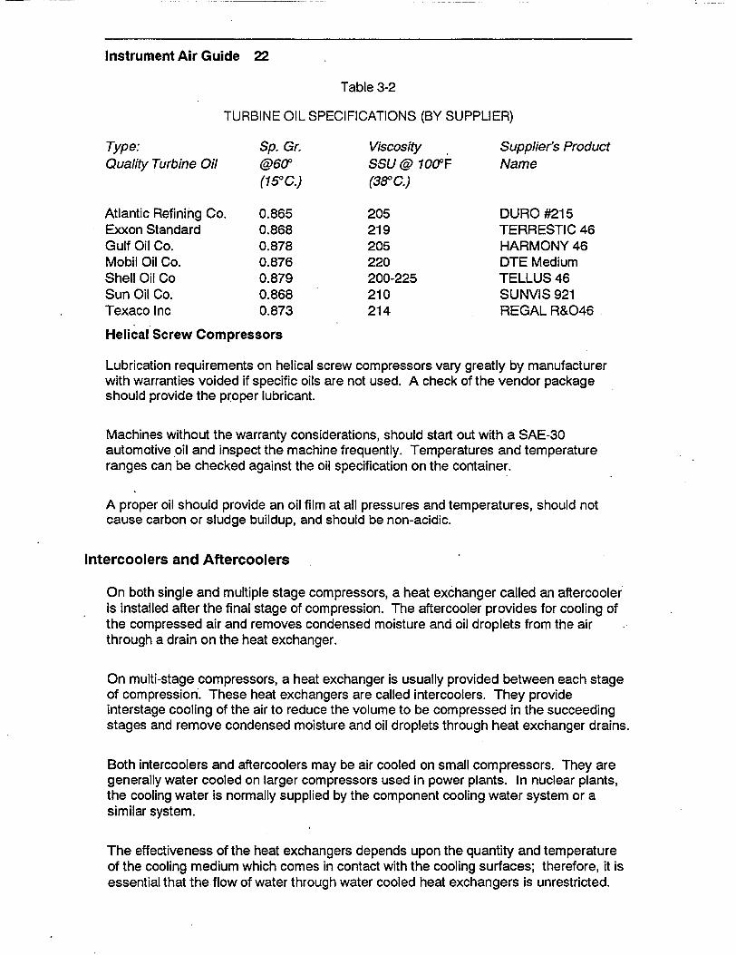
Dynamic air compressors, because of their high speeds, require a high quality petroleum based oil. This oil will perform for years without changing, provided a high degree of filtration is maintained. Atypical oil will be oxidation and rust. inhibited, resist foaming, and will not break down under operating temperatures and pressures. A few typical turbine oils, suitable for the purpose are shown in Table 3-2. This is not an exclusive list and other products may be available from the oil producers.
Instrument Air Guide 22
Table 3-2
TURBINE OIL SPECIFICATIONS (BY SUPPLIER)
Type: Sp. Gr. Viscosity Supplier's Product Quality Turbine Oil @60' SSU @ 100-F Name
(15°C.) (380 C.)
Atlantic Refining Co. 0.865 205 DURO #215 Exxon Standard 0.868 219 TERRESTIC 46 Gulf Oil Co. 0.878 205 HARMONY 46 Mobil Oil Co. 0.876 220 DTE Medium Shell Oil Co 0.879 200-225 TELLUS 46 Sun Oil Co. 0.868 210 SUNVIS 921 Texaco Inc 0.873 214 REGAL R&046
Helical Screw Compressors
Lubrication requirements on helical screw compressors vary greatly by manufacturer with warranties voided if specific oils are not used. A check of the vendor package should provide the proper lubricant.
Machines without the warranty considerations, should start out with a SAE-30 automotive oil and inspect the machine frequently. Temperatures and temperature ranges can be checked against the oil specification on the container.
A proper oil should provide an oil film at all pressures and temperatures, should not cause carbon or sludge buildup, and should be non-acidic.
Intercoolers and Aftercoolers
On both single and multiple stage compressors, a heat exchanger called an aftercooler is installed after the final stage of compression. The aftercooler provides for cooling of the compressed air and removes condensed moisture and oil droplets from the air through a drain on the heat exchanger.
On multi-stage compressors, a heat exchanger is usually provided between each stage of compression. These heat exchangers are called intercoolers. They provide interstage cooling of the air to reduce the volume to be compressed in the succeeding stages and remove condensed moisture and oil droplets through heat exchanger drains.
Both intercoolers and aftercoolers may be air cooled on small compressors. They are generally water cooled on larger compressors used in power plants. In nuclear plants, the cooling water is normally supplied by the component cooling water system or a similar system.
The effectiveness of the heat exchangers depends upon the quantity and temperature of the cooling medium which comes in contact with the cooling surfaces; therefore, it is essential that the flow of water through water cooled heat exchangers is unrestricted.

Instrument Air Guide 23
Cooling water flow can be monitored by installing flow or differential pressure gages. Cooling water inlet temperature should also be maintained within the specified range. Similarly, cooling fins on an air cooled heat exchanger should have unrestricted access to cooling air flow. An abnormal increase in the discharge air temperature or moisture content may indicate:
"* clogged heat exchanger tubes or closed circulation water valves "* higher than usual cooling water temperature "* inoperative drain valves or traps "* dirty air cooling fins or otherwise restricted air circulation "* high ambient air temperature (for air cooled heat exchangers)
If steps are not taken to restore proper operation of the heat exchanger, heated air will pass into the air receiver where cooling and condensation will finally occur. This may ultimately result in moisture carryover and tank corrosion.
The aftercooler should be located in the compressor discharge line between the compressor and the receiver and as near the compressor as possible. Preferable location is in the compressor room where its operation can be monitored and controlled readily. In any location it must be protected against freezing temperature and enough room must be provided for dismantling and cleaning. Full- size pipe connections between the compressor and tha aftercooler must be used to prevent pulsations in the pipeline. A bypass pipe should be installed so that the aftercooler can be removed for cleaning without shutting down the system.
In most types of aftercoolers, the cooling water enters at the bottom and discharges at the top. Cooling water should be regulated so that the discharge air is cooled to within 150F of the temperature of the inlet water (i.e. if the inlet water is 500F, outlet air temperature should not exceed 650F). If this limit of cooling cannot be achieved with full cooling water flow, it may indicate tube fouling or undersized heat exchanger. The colder the inlet water, the cooler the air will be leaving the aftercooler, and more moisture will be removed from the air.
The function of the intercooler is to remove the heat of compression from the air after it leaves the first stage compressor cylinder and before it reaches the second stage of compression. This reduces the air volume to be compressed in the second stage and improves the compression efficiency. At the same time, any moisture carried in the air is condensed and removed.
The most common cause of intercooler inefficiency is the use of dirty or hard, scale forming cooling water. Any coating either in the tubes or on the outside will lower the heat transfer. The tubes should be inspected at frequent intervals (refer to Appendix-A) and cleaned, if necessary.

Instrument Air Guide 24
Moisture Separators
Since moisture removal in the aftercooler is only as effective as the aftercooler's ability to lower the air temperature, any additional moisture is removed by the use of moisture separators. The moisture separators are usually installed in the air line between the aftercooler and the receiver. They also may be installed prior to components requiring additional moisture protection.
Most separators designed for instrument air use centrifugal force or redirection of flow to throw out water droplets. Others use felt disks, rotating elements, or porous stone disks to separate the moisture from the air. Some designs employ the use of a water cooled condenser inside the separator, making it similar to another aftercooler.
Once the moisture has been separated, usually it is removed by an automatic trap or blowdown valve controlled by a timer. On manual systems, accumulated moisture should be blown down regularly.
Plants which do not have moisture separators prior to the air receiver rely more heavily on the receiver to act as a moisture separator. This may cause accelerated corrosion of the receiver walls to below minimum wall thickness requirements and can become a safety hazard.
Receivers
Air receivers (or storage tanks) should be provided in all installations using positive displacement air compressors. Receivers, when liberally sized, greatly reduce the frequency of compressor loading. Use of a receiver with dynamic air compressors is not important because they operate to equalize the output with system demand. However, a receiver provides a storage capacity which can be used for a limited period of time in case of compressor failure.
Receivers serve the following functions: "* dampen the compressor discharge pulsations. "* serve as reservoirs to reduce the impact of sudden pressure changes during periods
of unusually heavy demand exceeding compressor capacity. "* prevent frequent loading and unloading of the compressor. "* serve to precipitate some of the moisture in the air that may have failed to condense
in the aftercooler and the separator.
For purposes of retrofit, or to investigate system operation, air compressor receiver capacities may be calculated. It is advisable, however, to consult a receiver manufacturer who may be aware of specific cases where additional capacities need to be added. Manufacturers can recommend required receiver wall thicknesses that allow for corrosion over the expected plant life. Incremental cost for an additional 1/8 to 3/16 of an inch thickness of tank metal or using corrosion resistant steel for tank fabrication is far less than the replacement or repair costs of a pressure vessel at the 13 or 14 year point of an expected 20 year life. Another important service the receiver manufacturer can provide is to recommend coatings that can save many replacement or repair costs.

Instrument Air Guide 25
The use of non ASME receivers is not recommended. Many federal, state, and local laws regulate the construction of unfired pressure vessels and they should be strictly adhered to. ASME receivers are furnished complete with ASME approved safety valves, pressure gages, handholes or manholes, and drain valves.
ASME vessels should be inspected periodically to check:
"* Proper pressure setting of the safety valve. It should be at least five (5) percent less than the stamped maximum pressure on the tank.
"* That the gage calibration is current. "* That the receiver is continually drained or periodically drained by shift routines.
Moisture accumulation can cause severe corrosion problems.
* Integrity of coatings, paint and corrosion inhibitors. Vessel should be recoated, if necessary.
Prefilters and Afterfilters
Instrument air dryers need to be fitted with prefilters and afterfilters to remove particulate, moisture, and hydrocarbons that are harmful to both the dryers and the end-use components. The prefilters protect the dryers and the afterfilters ensure air specifications are maintained in the distribution system. The filter selection is determined by the component selection and the system arrangement. The systems vary greatly from plant to plant even when the same end product is desired.
In addition to plant specific factors, the following list should be considered when selecting prefilters and afterfilters. For recommended filters, refer to filter selection chart in Appendix B.
"* The type of compressor selected and whether or not it is oil- free. "* The filtration capability of the intake filter. "* Receiver location in relation to the dryers. "* The type of aftercooler, air or water cooled, and its efficiency. "* Whether or not separators are installed before the dryer system. I The type of dryer installed, refrigerant or desiccant, heated or heatless. "• The type and condition of the desiccant. "• The end-use specification of the instrument air. "* Whether instrument air is used as breathing air or for ventilation.
Prefilters and afterfilters come in many types, variations, and sizes. Prefilters are basically of two types; dry cartridge filters and coalescing cartridges. The filtration capacities are stated in both absolute and nominal terms. A filter with a rating of 3.0 microns absolute will not pass any particulate larger than 3.0 microns. A 3.0 micron nominal filter will pass some particulate greater than 3.0 microns based on filter efficiency. In choosing a filter, have the vendor prescribe a nominal filter that will remove all of the particulate that needs to be removed while still meeting system flow requirements. Absolute filters are extremely expensive and may not adequately support flow.

Instrument Air Guide 26
Dry cartridge type filters have fibrous filter sections and are often coated with epoxy resin. Properly sized and selected these filters can remove particulate down to 0.01 microns without excessive pressure drops in the system, if correctly sized (reference 37).
Coalescing filters contain masses of microfilament that entrap the moisture and oil mists in addition to the filtration of the solid particulate. Moisture can be reduced to 0.02 ppm at about 70°F and to about 1.0 ppm at 1000 F.
Adsorber filters remove hydrocarbon odors and mists and are used in conjunction with the afterfilter in breathing air systems. Adsorber filters usually contain a type of activated carbon particle (charcoal) for a filter medium. The most common use of the coalescing filter is as a prefilter protecting dryers from moisture carry-over and hydrocarbon mist. When used with a refrigerant dryer it should remove all particulate greater than 10.0 microns and all moisture (99.9 percent plus) at 1.0 micron. Entrapment stops aerosols and oil mists; less than 1.0 ppm remains in the air stream. This affords the greatest protection to the refrigeration dryer while limiting the fouling and corrosion caused by the liquid entrained in the air.
When used with a desiccant dryer, the coalescing prefilter should remove particulate greater than 15.0 microns and all moisture (99.9 percent plus) at 0.3 microns. Entrapment eliminates aerosols and oil mists to less than 0.1 ppm.
On refrigerant dryers, afterfilters are only required where the processed air is above desired particulate specification. An absolute 3.0 micron afterfilter will be sufficient to meet ANSI/ISA specification as far as particulate count. A coalescing filter may provide dew points below 350 F.
Afterfilters for desiccant dryers should be dry filters with a filtration capability to capture particulate to 1.0 micron nominal and 3.0 absolute. This permits the capture of desiccant fines. If tests show many particles nearing the 3.0 micron range, a finer mesh filter should be used. Desiccant fines cause service damage to end-use components.
A final coalescer or adsorber can now be used to gather hydrocarbon mists. This filter is usually installed last in line for cost reasons. A coalescent filter element is more expensive than a regular particulate filter. Placing it prior to the particulate filter would require more frequent coalescent filter element replacement than particulate filter changeout, thus increasing maintenance costs.
In summary, each system should be examined component by component for filter selection factors. All of the major manufacturers of filters can supply the filter type and size required. Filter vendors should meet your plant requirements and should be called upon to recommend proper methods to solve your filtration problems.
Air Dryer
Instrument air dryers in use in the power industry generally fall into the following types:

Instrument Air Guide 27
"* Desiccant - Heat Regenerative "* Desiccant - Heatless Regenerative "* Refrigeration
Numerous manufacturers produce the various types of dryers. A discussion of the theory of operation of the above types follows. The manufacturers have different designs and controls, but the overall operation of each type is similar.
Heat Regenerative Dryer
In heat regenerative desiccant dryers (Figure 3-6), the moist inlet air enters the dryer 'through the inlet switching valve (A) and is routed to either the left or right tower (B). While the air flows through the tower, the moisture is adsorbed onto the desiccant. After drying, the air leaves the dryer outlet (C). Regeneration of the exhausted tower is accomplished by heating the desiccant. Desiccant can be heated by using embedded heaters (D), as shown in figure 3-6, or by passing externally heated air over the desiccant bed. When the desiccant is heated, the moisture is desorbed from the desiccant. In case of externally heated air, the flow of air carries the moisture away. In case of internal heaters, the moisture is removed from the dryer by using approximately five (5) percent of the dry air as reactivation air (purge air). This reactivation air is routed back through the dryer and exits through the reactivation air outlets (E) to atmosphere. This type of dryer usually operates on an eight (8) hour cycle.
With embedded heaters sometimes hot spots might occur in the desiccant bed. Desiccant beads subjected to these high temperatures may crumble creating fines. It is
MOIST AIR INLET
REACTIVATION AIR INLET SWITCHING
OUTLET VALVES (E)- • VALVE (A)
LEF I I MOSTURE I I R IGGT TOWE TOOOW
HETTEPEREATEE
(D) q T(0)
Figure 3-6. Heat Regenerative Desiccant Dryer

Instrument Air Guide 28
therefore important to note the maximum temperature of the bed during regeneration and the capability of the desiccant to withstand this temperature.
Heatless Regenerative Dryer
In heatless regenerative desiccant dryers (Figure 3-7), the moist inlet air enters the dryer through the inlet switching valve (A) and is routed to either the right or left tower (B). While the air flows through the tower, the moisture is adsorbed onto the desiccant. After drying, the air leaves the dryer outlet (C). Regeneration of the off-line tower is accomplished by taking 15 to 20 percent of the dry outlet air and routing it through the off- line tower and then to atmosphere via the purge muffler (D). Regeneration and drying cycles are controlled by using either timers or moisture probes (E). The moisture probes sense the moisture content of the desiccant. The purge control throttle valve is adjusted to ensure proper flow rate of the purge air throughout the regenerating tower for optimum regeneration efficiency. The tower repressurization valve provide for a slow repressurization of the regenerated tower before it is placed back on line to reduce the pressure surge in the tower and the resultant compaction and breakdown of the desiccant. The control air isolation valve isolates the air to the control panel. These dryers usually operate on 10 minute cycles. This type of dryer may starve the distribution system in plants with marginal capacity due to their high purge air requirements. Before installing a heatless desiccant type dryer, ensure that the compressors have 15 to 20 percent excess capacity.
PURGE CONTROL THROTTLE VALVE
TOWER REPRESSURIZATION VALVE
TOWER DEPRESSURIZING VALVE
Figure 3-7. Heatless Regenerative Desiccant Dryer

Instrument Air Guide 29
Refrigerant Dryer
In refrigerant dryers (Figure 3-8), moist inlet air enters the dryer precooler (A) and is cooled by the dry air leaving the dryer. The moist air then enters the evaporator (B) where it is cooled by the refrigerant. Most of the moisture is condensed and removed in the evaporator. Air leaving the evaporator is 33 to 350F. Any excess moisture entrained in the air condenses in the separator (C) and is removed by using a drain trap (D). The dry air leaves the separator and returns to the precooler (A) where it is heated by the moist inlet air prior to distribution.
The air will remain dry throughout the system as long as it is not cooled below the evaporator temperature. Refrigerant dryers do not work well if the distribution system is exposed to freezing temperatures. When the instrument air temperature drops below freezing, the moisture forms sleet or ice crystals in the air line, causing a loss of air supply to end-use components.
Figure 3-8. Refrigerant Dryer

Instrument Air Guide 30
To maintain air quality that consistently meets ANSI/ISA S7.3-1975 dewpoint criteria, a regenerative desiccant dryer (heatless or heated) is recommended. Regenerative desiccant dryers can consistently maintain the dewpoint at -40°F or below at line pressure with 1 00°F saturated inlet air. This is well within ANSI/ISA specifications.
Refrigerant type dryers can only provide dewpoints of +35 to +500F, but ANSI/ISA S7.3 does not allow dewpoints exceeding 35°F at any time. For this reason we do not recommend the use of refrigerant type dryers for instrument air as primary installation. However, they can be used in series with desiccant type dryers, downstream of them, prior to air distribution to end-use components.
Deliquescent Dryer
Another dryer in limited use in compressed air systems is the deliquescent dryer. These dryers reduce the dewpoint by chemical absorption process using hygroscopic salts or organic compounds as desiccant. In the process of drying the desiccant physically changes from solid to liquid state. The desiccant is specially formulated to allow the process air to reach a predetermined relative humidity. Dewpoint suppression of 10 to 40°F below inlet air temperature is attainable. Saturated inlet air at 1 00°F yields dewpoints as low as 60°F at the dryer outlet. These dryers cannot consistently meet the ANSI/ISA S7.3-1975 dewpoint criteria; therefore, they are not recommended for use as a primary source for instrument air drying.
Desiccants
Most commonly used desiccants are,
* silica gel * activated alumina * molecular sieve.
Silica gel is available in both granular and beaded form. In beaded form it has the high resistance to attrition and produces little or no fines. Silica gel's ability to achieve -40°F dewpoints at 100 to 125 psig line pressure and its low regeneration temperatures make it an extremely cost effective medium for instrument air drying applications.
Lower dewpoints can be obtained at less cost using activated alumina; However, it is susceptible to greater percentage of fines and requires slightly higher regeneration temperature.
Molecular sieve has the capability to adsorb small molecules while excluding the large ones. Therefore, it should only be used as a polishing or trimming agent in a mixed bed operation. Use of molecular sieve as a primary agent may not remove sufficient moisture in dryers with small desiccant capacities. Also, the regeneration temperature for molecular sieve is higher than silica gel or activated alumina. Table 3-3 shows the various desiccant types available and the reason to use each type.

Instrument Air Guide 31
Table 3-3
DESICCANT TYPES
Dryer Type Preference Desiccant Type Reason to use
Heated 1. Beaded Silica Most resistant Regenerative Gel to attrition and
lower regeneration costs
2. Beaded Silica To be used with Gel (water beaded silica gel blocker) when in direct contact
with water to resist fracturing
3. Activated Lowest initial cost Alumina
4. Molecular To be used in a mixed Sieve bed as a trim or
polishing desiccant only
Heatless 1. Activated Most cost efficient Regenerative Alumina for heatless dryers
2. Beaded Silica To be used to Gel control attrition
only
3. Beaded Silica To be used with Gel (water beaded silica gel blocker) when in direct contact.
with water to resist fracturing
4. Molecular To be used in a Sieve mixed bed as a trim
or polishing desiccant only
Deliquescent 1 Vendor recommen- Limited use ded Water Soluble Salts or organic compounds

Instrument Air Guide 32
Blowdown Devices
It is necessary to provide a method of removing condensed moisture or oil droplets collected at various points in the compressed air system. Some manufacturers incorporate automatic valves, others use drain traps. No matter which method is employed it should be designed to have minimum impact on air system pressure and capacity. Most manufacturers use drain traps for moisture removal from inter and aftercoolers, moisture separators, and receivers. These usually consist of a reservoir that allows moisture to collect to a predetermined level and a float valve that actuates allowing the air pressure to blow the water into a drain. Some manufacturers use a timer-actuated solenoid valve opening for a few seconds on a preset time schedule to blow the air line down. The automatic drain valves associated with intercoolers must be checked regularly. If the condensate is carried into the second stage cylinder, it will wash away cylinder lubrication (on lubricated compressors) and may damage the cylinder.
In addition to the use of drain traps and blowdown valves in the instrument air system, it is recommended that the various airlines to the end-use components be manually blown down periodically to facilitate the removal of particulate contamination from the system.
Manual blowdowns are particularly important in older instrument air systems that have been upgraded to meet ANSI/ISA S7.3-1975. Systems that have been operated for a long period of time with moisture in the air may have plating of corrosion products on the pipe walls. Upgrading systems to a sub-zero dew point will dry out this plated layer causing it to spall and contaminate the air stream.
System Piping and End-use Components
Pressure drops between the compressor and end-use components are non-recoverable losses; therefore, it is imperative that pressure losses be minimized. When designing or modifying a system, the following guidelines should be followed:
"* Pipe sizes should be large enough to ensure pressure drops after the receiver do not exceed 10 percent of system pressure.
"* Long distribution lines should have liberally sized air receivers located near the far ends or near points of heavy demand.
"* Where possible, a loop type of system around the plant or building is recommended. This provides a two-way distribution to the point where air demand is highest. The loop piping should be of sufficient size so that pressure drop is not excessive at any component, regardless of direction of flow.
"* Each air header or main should have the outlets located as close as possible to the point of use. This is to prevent excessive pressure drops through hoses. Outlets should always tap off from top of the pipe to prevent any condensation, oil or other particulate from being carried over to the component.
"* All piping should be sloped toward 'a drop line or trap to enable condensation to be removed from the system.
• For systems that use only oil-free compressors, it is recommended that corrosion-resistant pipe be used.

Instrument Air Guide 33
"* On oil lubricated compressor systems, an oil film will form on the pipe walls and help protect the pipe from corrosive effect of the warm moist air. This protection is not available in a non-lubricated compressor system.
"* System piping should be well supported yet allow for movement of the pipe due to operationally induced stresses. The span between hangers should be kept short enough so that the sag will not exceed the downward pitch of the pipe wall.
Instrument air system piping materials vary a great deal between the various power plants. Plants generally use carbon steel, hard copper, stainless steel, galvanized steel or a combination of two or more types. Each type of pipe has its own advantages and disadvantages for use in an air system.
Hard copper piping (Class 212) is in common use at many facilities, but such systems are susceptible to joint failures. In order to strengthen the joints and lessen the possibility of failures, some plants require that copper piping joints be brazed instead of soldered; others use stainless lines for supply to user components. Some of those facilities that achieved the goal of "clean dry air" have opted to replace their copper lines with carbon steel piping with welded joints. Sufficient studies have not been made at this time to recommend this practice.
End-use components include such things as solenoid valves, in-line filter/pressure regulators, I/P controllers, valve operators, level and flow controllers, and anything else that uses instrument air for its operation. Failure to maintain high quality air will ultimately in the failure of the user component. Many plants (both, fossil and nuclear) have had repeated equipment failures and resultant outages which can be directly attributed to the degradation of instrument air quality.
The isolation of the condensate polishers that started the Three Mile Island Unit 2 accident was attributed to water in the instrument air system (Reference 28). Several plants have had difficulty in maintaining circulating and service water flow during extreme cold weather due to air operated valves not working properly. Maintenance personnel have removed the operators, transported them to the workbench, bench tested them, and they worked fine. This scenario has been repeated, year after year,, plant after plant. The valves have always seemed to catch the blame. "Everyone knows that these valves aren't worth a damn in cold weather!" is often overheard in the shop. Too many times, the real culprit was not the valve but the instrument air line which was frozen due to water in it.
Some end-use components that are required to operate after a loss of air have backup bottles of high pressure air or nitrogen piped in via a pressure regulator to maintain operability. These backup bottles are usually sized to allow either a calculated number of strokes for a valve or to guarantee an air supply for a certain period of time. When high pressure backup bottles are used, the relief valve between the pressure regulator and the valve operator should be sized to handle the entire capacity of the bottle(s). This will ensure the lower pressure piping is not overpressurized should the pressure regulator fail.

Instrument Air Guide 34
In some nuclear facilities, a nitrogen atmosphere is used inside the containment during operation. These plants also use nitrogen to supply the instrument air system inside the containment. Any leakage of nitrogen inside the containment instrument air system simply adds to the nitrogen atmosphere. Containment is not normally accessible during plant operation.

Instrument Air Guide 35
4.0 SYSTEM AIR QUALITY REQUIREMENTS
Instrument air quality criteria currently in use are the Instrument Society of America's Standard ISA-S7.3-1975 and the various manufacturers recommended specifications. ANSI/ISA-S7.3-1 975 establishes the following criteria for instrument air:
Particulate - There shall be no particulates larger than three(3) microns.
Dewpoint - The dewpoint at line pressure is at least 1 80F below the lowest expected ambient temperature and in no case higher than 350F.
Hydrocarbons - There shall be less than one (1) ppm hydrocarbon contamination.
For air quality component manufacturers in most cases recommend, "clean, dry, oil-free air". Some specify particulate sizes from five (5) to 40 microns. The ANSI/ISA-S7.3-1975 standard is based on considering the needs of the air operated instruments and the capabilities of commercially available equipment.
The particulate requirement of three (3.0) microns is based on discussions with component manufacturers and corresponds to the requirements for the most restrictive components. Three (3) microns is readily achievable with commercially available equipment (Reference 2). Air blow period for collection of particulate sample is not specified and vary from plant to plant, ranging from one (1) minute to one (1) hour. One utility has purchased a laser-based system to continuously monitor instrument air for particulate. If for any reason this particle count cannot be met, then the plant should evaluate the effect of higher particulate content on each individual component to develop own specific criteria.
The dewpoint criteria is based on ensuring that no water is present in the instrument air system with some margin. The upper limit of 350F is based on the lowest dewpoint achievable using a refrigerant dryer (Reference 2).
The hydrocarbon specification is based on assuming an oil content of five (5) to eight (8) ppm downstream of an oil-lubricated reciprocating compressor with a coalescing filter operating at 90 to 95 percent efficiency downstream of the compressor (Reference 2).
Air in the system should be sampled semi-annually (see Appendix-A) to ensure that air quality is being maintained. The system should be sampled on the downstream side of the dryer as close to outlet of the afterfilter as possible. This provides assurance of the quality of the air supplied to the system. Other samples may be taken elsewhere in the system, but may not be an accurate indication of whether the dryer and filters are operating properly. These samples may only detect spalled particulate in the system and indicate a need for blowdowns.

Instrument Air Guide 36
Moisture content should be continuously monitored by the use of a permanent dew cell or moisture indicator installed on the downstream side of the dryer. It can be extremely useful in early detection of instrument air system problems.

Instrument Air Guide 37
5.0 INSTRUMENT AIR SYSTEM PROBLEMS AND CAUSES
In a recent EPRI-Nuclear Safety Analysis Center publication (NSAC- 128, October 1988) a review of industry-wide pneumatic system problems indicated that 49 percent of all failure events resulted from contamination in the system, and only 28 percent were attributed to component failures, such as check valves. It is possible some of the component failures also occurred due to contamination in the instrument air system. This means that contaminants are the largest single contributor to instrument air system failures. Other problems that cause aggravation to maintenance departments are leaks and component failures
Contaminants
Major contaminants in instrument air systems are:
* Dirt or dust particles 9 Corrosion or rust particles * Moisture or water * Desiccant fines a Oil mist
A paper in the proceedings of American Power Conference attributed up to 90 percent of the problems in non-lubricated compressors to the incursion of dust or rust particles in the intake pipe (Reference-4). It also suggested that intake lines be made of noncorroding materials such as galvanized steel or aluminum.
Dirt or rust particles cause damage to a compressor cylinder by scoring. Cylinders of non-lubricated compressors are specially honed to a fine finish to reduce the friction coefficient between the TFE piston rings and the cylinder wall surface. Therefore, it is more important to prevent the incursion of foreign particles into a non-lubricated compressor than a lubricated one.
A proper air intake filter is an important defense against incursion of dust or dirt into system piping. However, a clogged filter unit can starve the compressor and result in a substantial reduction in discharge pressure and capacity. Contamination levels vary greatly between installations. High levels of contamination may be inadvertently released in the vicinity of an intake filter by unrelated construction or maintenance work. The only reliable method of determining if a filter requires cleaning or replacement is by measuring pressure drop across the filter. This can be done by a U-tube manometer or by installing a differential pressure gage across the filter housing. Differential pressure should be measured periodically. If the pressure drop across the filter exceeds the manufacturers' recommendation, the filter should immediately be cleaned or replaced. However, intake filters should also be replaced based on periodic maintenance schedule, even if the differential pressure is within limits. A sudden drop in the differential pressure across the filter may indicate a torn or damaged filter element and should be investigated further for possibility of needing replacement. Recommended sizes for intake filters are discussed in Section 3 and Appendix-B of this manual.

Instrument Air Guide 38
Rust in the system usually occurs due to corrosion of either the receiver or the system piping. The cause of corrosion of the receiver or piping is one or more of the following:
* Original installation of improperly cleaned equipment or piping. * Humidity and moisture (water) incursion into the system between installation and
startup phases. * Improper operation of filter or dryer units. * Frequent cross-connection of instrument air and service air headers. * Leakage of cooling water into the air system via compressor cooling lines or, inter
and aftercooler heat exchangers. * Malfunction of drain traps, allowing water to accumulate and be carried through the
system piping.
It is impossible to predict when a corrosion product (rust particle) will dislodge itself, travel through the system piping, and lodge itself into a component, rendering it inoperable. Solenoid valves, pneumatically operated valves, pilot valves, and I/P converters are especially vulnerable to failure due to foreign particle incursions.
Once the system piping is initially cleaned, incursion of foreign particles from atmosphere can be prevented by the proper use of intake filters on the compressor suction. Rust particles generated within the receiver tanks and distribution system piping up to the dryers, can easily be removed from the system by using prefilters on a refrigerant dryer. In addition, these particles will be filtered out by the desiccant on a desiccant type of dryer.
Some utilities have used copper piping for their instrument air supply in an effort to prevent corrosion inside their distribution system. Copper piping is more susceptible to bending and breakage than carbon or galvanized steel, and compression fittings on copper tubing are more likely to develop leaks due to line vibration.
To maintain proper air quality required for operation, it is necessary to:
"* Thoroughly review system design to ensure that the components have the capability to produce the quality and quantity of air to meet plant needs. Review should include any purge air requirement for the dryers.
"* Ensure that the system, upstream of the dryers, is either chemically cleaned or blown down to remove as much of the corrosion and contamination as possible.
* Place the system on line with proper dewpoint air leaving the dryer. Perform blowdowns of the system, downstream of the dryers, to remove any loose particulate. These blowdowns need to be performed shortly after placing the dryers in service, and again two weeks to a month later. After the initial period, blowdowns should be performed on a 12 to 18 month cycle to ensure a clean system.
* Locate any cross-connection of service air and instrument air, upstream of the dryers to prevent moisture incursion into the system. This will also ensure that the air is dry before reaching the end-use components.

Instrument Air Guide 39
Properly maintain system traps and drains, prefilters and dryers. It is generally not recognized that a large volume of water needs to be removed during the process of compressing and cooling of air. The following example is used to give an idea of the quantity of water handled through the intercoolers and aftercoolers during the compression process. Table 5-1 shows the moisture content of saturated air in gallons per 1000 cubic feet of air at various temperatures and pressures.
Table 5-1
MOISTURE CONTENT OF SATURATED AIR IN GALLONS PER 1000 STANDARD CUBIC FEET
Temperature, 'F
PSIG 35 40 50 60 70 80 90 100 110 120
0 .0392 .0479 .0702 .1016 .1450 .2046 .2857 .3956 .5443 .7460 10 .0233 .0283 .0416 .0600 .0854 .1200 .1667 .2290 .3119 .4217 20 .0165 .0201 .0295 .0426 .0605 .0849 .1176 .1612 .2186 .2939 30 .0128 .0156 .0229 .0330 .0469 .0657 .0909 .1243 .1682 .2256 40 .0105 .0128 .0187 .0269 .0383 .0536 .0741 .1012 .1367 .1830 50 .0089 .0108 .0158 .0228 .0323 .0452 .0625 .0853 .1152 .1540 60 .0077 .0093 .0137 .0197 .0280 .0391 .0540 .0737 .0995 .1329 70 .0068 .0082 .0121 .0174 .0246 .0345 .0476 .0649 .0876 .1169 80 .0060 .0074 .0108 .0155 .0220 .0308 .0425 .0580 .0782 .1043 90 .0055 .0067 .0098 .0140 .0199 .0279 .0385 .0524 .0706 .0942
300 .0050 .0061 .0089 .0128 .0182 .0254 .0351 .0478 .0644 .0858 110 .0046 .0056 .0082 .0118 .0167 .0234 .0323 .0439 .0592 .0789 120 .0043 .0052 .0076 .0109 .0155 .0216 .0298 .0407 .0548 .0729 130 .0040 .0048 .0071 .0102 .0144 .0201 .0278 .0378 .0509 .0678 140 .0037 .0045 .0066 .0095 .0135 .0188 .0260 .0354 .0476 .0634 150 .0035 .0042 .0062 .0089 .0126 .0177 .0244 .0332 .0447 .0595 160 .0033 .0040 .0058 .0084 .0119 .0167 .0230 .0313 .0421 .0561 170 .0031 .0038 .0055 .0080 .0113 .0158 .0217 .0296 .0398 .0530 180 .0029 .0036 .0052 .0075 .0107 .0149 .0206 .0281 .0378 .0503 190 .0028 .0034 .0050 .0072 .0102 .0142 .0196 .0267 .0359 .0478 200 .0027 .0032 .0048 .0068 .0097 .0136 .0187 .0254 .0342 .0455
Let us assume that a compressor is operating at an ambient temperature of 1 00°F at atmospheric pressure. From Table 5-1, it can be noted that saturated air at atmospheric pressure and 1 O0°F contains 0.3956 gallons of water per 1000 f 3 of air. If this air is compressed to 100 psig and cooled to 80°F, the water content in the air will only be 0.0254 gallons per 1000 ft of air. This is equivalent to a removal of (0.3956 - 0.0254) 0.3702 gallons of water per 1000 ft3 of air, or 22 gallons per hour for a 1000 CFM capacity compressor. From the example it is easy to see why it is vital to maintain traps and drains in good operating condition. If the drains and traps are clogged, the cooler shells will fill up with condensate in a short period of time and then be carried over into the system in the form of heavy water droplets. These droplets may:
"• Deposit in the receiver and cause corrosion of the tank walls and bottom. "* Prematurely exhaust the capacities of prefilters and desiccant dryers. "• Overload refrigerant type dryers.
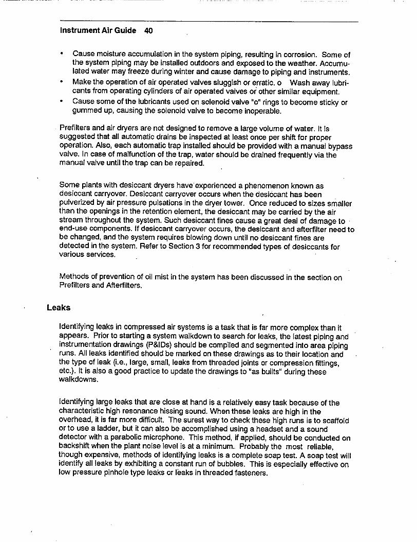
Instrument Air Guide 40
"* Cause moisture accumulation in the system piping, resulting in corrosion. Some of the system piping may be installed outdoors and exposed to the weather. Accumulated water may freeze during winter and cause damage to piping and instruments.
"* Make the operation of air operated valves sluggish or erratic. o Wash away lubricants from operating cylinders of air operated valves or other similar equipment.
"* Cause some of the lubricants used on solenoid valve "o" rings to become sticky or gummed up, causing the solenoid valve to become inoperable.
Prefilters and air dryers are not designed to remove a large volume of water. It is suggested that all automatic drains be inspected at least once per shift for proper operation. Also, each automatic trap installed should be provided with a manual bypass valve. In case of malfunction of the trap, water should be drained frequently via the manual valve until the trap can be repaired.
Some plants with desiccant dryers have'experienced a phenomenon known as desiccant carryover. Desiccant carryover occurs when the desiccant has been pulverized by air pressure pulsations in the dryer tower. Once reduced to sizes smaller than the openings in the retention element, the desiccant may be carried by the air stream throughout the system. Such desiccant fines cause a great deal of damage to end-use components. If desiccant carryover occurs, the desiccant and afterfilter need to be changed, and the system requires blowing down until no desiccant fines are detected in the system. Refer to Section 3 for recommended types of desiccants for various services.
Methods of prevention of oil mist in the system has been discussed in the section on Prefilters and Afterfilters.
Leaks
Identifying leaks in compressed air systems is a task that is far more complex than it appears. Prior to starting a system walkdown to search for leaks, the latest piping and instrumentation drawings (P&IDs) should be compiled and segmented into area piping runs. All leaks identified should be marked on these drawings as to their location and the type of leak (i.e., large, small, leaks from threaded joints or compression fittings, etc.). It is also a good practice to update the drawings to "as builts" during these walkdowns.
Identifying large leaks that are close at hand is a relatively easy task because of the characteristic high resonance hissing sound. When these leaks are high in the overhead, it is far more difficult. The surest way to check these high runs is to scaffold or to use a ladder, but it can also be accomplished using a headset and a sound detector with a parabolic microphone. This method, if applied, should be conducted on backshift when the plant noise level is at a minimum. Probably the most reliable, though expensive, methods of identifying leaks is a complete soap test. A soap test will identify all leaks by exhibiting a constant run of bubbles. This is especially effective on low pressure pinhole type leaks or leaks in threaded fasteners.

Instrument Air Guide 41
Once a leak has been identified, the maintenance action is only starting. Depending on location of the leaks, different corrective action options need to be considered.
If the leak is at a mechanical fastener (threaded or compres-sion type fitting) just tightening it may not be sufficient. Retest again with soap after repair. If a significant amount of leaky joints (three (3) to five (5) percent) are found, the piping should be inspected for hangers, snubbers, etc. It is possible that pipe harmonics are causing some of the difficulties. In any case strengthening the system by the use of stronger fasteners may be looked into to help solve this problem. It may be necessary to shift to steel pipe and use unions if soft copper instrument tubing is presently used.
Soldered joints in copper tubing runs are difficult to repair. Some nuclear plants use an approved brazing specification in accordance with the station welding procedure when repairing soldered joints, as there is no soldering specification in most welding programs. Others can refer to the ASME code for brazing specifications.
Through-wall leaks in pipes and pressure vessels are an indicator of serious problems. A pipe with a through-wall leak should not be patched except for a temporary fix and the pipe run should be tested by a non-destructive test such as ultrasound or radiograph. The section of pipe with leak should be discarded. Adjoining pipes or pipes in similar orientation or use should be spot checked for a common cause.
Normally, through-wall leaks are in carbon steel pipes where oxygen pitting or severe rust has thinned the pipe wall. This often occurs at low spots in pipe where temperature changes permit the moisture to condense and air flow isn't enough to move the water to the drain point.
Through-wall leaks in a pressure vessel such as an accumulator, dryer, or receiver are a much greater problem. These ASME code vessels have state requirements for testing. Maintenance supervisors should ensure that they are notified immediately of a pressure vessel through wall leak so plant management can take corrective measures.
In nuclear facilities, accumulators backup safety related segments of the system. These segments are normally protected by dual check valves. These valves cannot be allowed to leak and should be checked by a local leak rate test periodically in accordance with NUREG 1275 or ASME Section XI. If these valves are permitted to leak, accumulators will bleed off faster than their designed rate and will not provide the designed basis function.
It must be remembered, however, that leaks in instrument air systems are almost always indicators of far more significant system problems. Leakage may result in major operational problems adding significantly to the cost of plant operation. A large number of unattended leaks may interfere with system operation by lowering system header pressure. Most air operated equipment and instruments in a power plant are rated for operation between 85-100 psig air pressure. Any degradation of air pressure in the header will interfere with the proper operation of these components, resulting in unexpected responses.

Instrument Air Guide 42
An industry wide survey recently conducted by NSAC (Reference 1), records actual failure incidents of the following types due to a gradual degradation of instrument air pressures:
* Sluggish response of air operated valves. * Failure of check valves to close on gradual loss of air.
* Unusual sustained loss of air caused a LOCA outside containment.
Reference 28 also records an incident where Main Steam Isolation Valves (MSIVs) had failed to close because check valves in the air line, which were designed to close on loss of pressure and maintain air pressure to the MSIV operators, failed to close on gradual depressurization.
These incidents clearly show that even though instrument air systems are designated as "non-safety related", malfunctions in the systems may result in a plant shutdown. To realize the economic impact, consider that the cost of a single scram in a nuclear unit has been estimated to be on the order of $1.0 million (Reference 1).
In some power plants, the service air system is used as a backup to instrument air system. When a loss of instrument air pressure occurs, the two systems are cross-connected automatically or manually and the instrument air pressure is maintained by the service air system pressure. This cross connecting will cause gross moisture contamination of the instrument air system unless it occurs prior to dryer pre-filters.
Table 5-2 shows an estimated volume of air loss per month through various size openings and annual cost of lost air. The total cost of wasted air has been calculated based on an installation of a two-stage reciprocating compressor, assuming an adiabatic compression and a 15 percent horsepower loss due to friction. This is a very conservative estimate for an efficient installation. (A sample calculation is attached in APPENDIX-C). It should also be noted that the cost of lost air shown in this table is from a single opening of the size indicated and is based on electric power consumption only. Other indirect costs, such as, pro-rated O&M cost, equipment depreciation, capital cost, reduced equipment life due to additional run time, etc. are not included.
Table 5-2
ESTIMATED VOLUME OF AIR LOSS THROUGH LEAKAGE AND ASSOCIATED COSTS
Size of Volume of air Energy consumption Annual cost opening lost per month to compress the lost of lost air inches @ 100 psi air volume @ $0.10 per
(nozzle coef. KWh per month KWh = 0.65), Ft3
3/8" 6,671,890 14,678 $17,614.00 1/4" 2,920,840 6,426 7,711.00 1/8" 740,210 1,628 1,954.00

Instrument Air Guide 43
From Table 5-2 it is clear that regular system walkdowns to identify and repair air leaks will pay handsomely in 0 & M cost savings.
Failed Components
Component failures in the instrument air systems can be grouped into:
(1) air supply component failures, and
(2) end-use component failures.
Usually a complication in the supply side components is what causes the eventual end-use component failure. Most common trouble spot among the instrument air supply side components are filters.Filters require periodic inspection as well as cleaning and changing. The filter differential pressure limits should be marked on the filter housing and the shift routines should provide a method to ensure limits are not reached. Even though filters in an instrument air system should be able to withstand full system pressure, the lack of air flow by a blocked filter can lead to plant air loss.
The second most common filter failure is due to the use of an improper sized filter element. It is very easy for a 0.1 micron filter element to plug when it is housed where a 20 micron filter should be. Some times an old partially used filter finds its way back into the system without proper cleaning. (See Section 6 for Maintenance Recommendations on Prefilters and Afterfilters):
Improper filter use is extremely expensive in both maintenance time and casualty repair costs. It is also one of the easiest to correct. A few easy rules save many maintenance dollars.
Compressor failure is another common casualty in a power plant. Most power plants have special alarms dedicated to this casualty because its effects can be very damaging. Some plants have one or two redundant compressors as backup and many have installed receiver banks and special accumulators to further mitigate effects of a compressor loss. As in many other component failures, lack of proper maintenance is a big offender in these occurrences. It shows as lack of lubrication, dirt incursion in the oil system, failed tubes in an aftercooler, crud clogged valves, and on and on.
Vendor information and technical manuals tell us the air compressor should provide many years of trouble free service if it is properly maintained. Towards this goal the maintenance personnel should thoroughly inspect their individual system with special attention to lubrication, filtration, and operating temperatures. They also should periodically test their system to ASME code requirements. If all these parameters are maintained within specification, all machines, irrespective of make and model, will provide reliable service.

Instrument Air Guide 44
Dryer failures contribute significantly to the failure of many end- use components. While a dryer is off-line or not performing to full capacity, moisture is entering the system.
One of the most common problems, especially with single train dryers, occurs when a prefilter clogs and the differential pressure goes past the limit. The operator manually compounds the problem by bypassing the dryer. It is far better to bypass the filter or even remove the element than it is to bypass the entire dryer train. Similar situations may arise when the dryer towers experience shifting difficulties and the desiccant in one tower is too wet. It is strongly recommended not to bypass the dryer - desiccant working partially is better than none at all. When dryers shift rapidly or try to shift and can not, desiccant breaks down. The resulting fines are too small for many afterfilters, and system contamination may result.
Dryers, timers, switching mechanisms, and heaters require periodic maintenance to perform properly. Each'maintenance department should treat this equipment as the heart of the plant because without it all other systems will soon be experiencing difficulties.
Most end-use component failures are caused by contamination of the instrument air system. Among the most common failures in end-use components to occur is the solenoid valve. A solenoid valve usually has "o" rings that provide the sealing surface for the valve disk. If any particulate contamination becomes attached to the "o" ring, it can cause the valve not to seal properly, or not work at all. Some of the lubricants used on the "o" rings by the various utilities are water soluble and any moisture can cause the lubricant to become sticky and feel somewhat like rubber cement'
Moisture tends to gum up the valve and keep it from working properly. The rubber "o" rings are also highly susceptible to damage from hydrocarbon contamination. The oil or hydrocarbon contamination breaks down the "o" ring chemically and may cause it to either deteriorate or swell, thus making the solenoid valve inoperative. (Reference 36). The vent line on the solenoid valve is specially sized to allow a certain flow rate of air to issue from the vent when the solenoid is actuated. This flow rate has a direct impact on the cycling time of the air operated equipment. If this vent line is pinched or blocked, the air operated valve's stroke time may be out of specification or the valve may not work at all.
Another component that is very susceptible to air line contamination, particularly any dirt or rust, is the I/P converter. Due to extremely small ports inside the I/P converter any dirt or rust that enters the instrument can start plugging ports and causing sluggish response.
Most I/P converters in use in the power industry have pressure/filter regulators in the air line just upstream of the I/P converter. Filter regulators usually have an intake screen to filter the air. This intake screen is generally provided with a petcock at the bottom of the regulator. This petcock should be opened periodically to blow any particulate or foreign matter out of the regulator to keep the screen from clogging and blocking air flow through the regulator. If any water is present in the air line, it will also be blown out.

Instrument Air Guide 45
Drain trap failures are usually due to foreign matter fouling the seating surfaces so that they do not fully seat when closed. This allows the trap to constantly blow through and slowly depressurize the system. The compressor usually maintains this added load with little difficulty, but it causes more compressor run time. Result is same as a constant leak in the system. Another common failure in the drain trap is the collection of rust and other corrosion products that can cause the trap to stick shut. This keeps the trap from draining the moisture from the line and can lead to moisture carryover and overload the dryer.
Pneumatic valve operators are also known to fail. They usually fail due to contamination of the instrument air. The diaphragms may be made of a neoprene or rubber compound that deteriorates in the presence of hydrocarbon contamination. They may also collect dirt and rust, thus ultimately filling up or causing the valve to stick or not fully stroke by restricting its movement.
Air line check valves can be rendered inoperable by dirt and rust particles. Foreign matter on the seating surface can stop the check valve from seating completely, permitting accumulator pressure to backflow into the instrument air system. This seriously degrades the safety related function because the accumulator will not have the design pressure and volume to operate the valve.

Instrument Air Guide 47
6.0 MAINTENANCE PHILOSOPHY AND RECOMMENDATIONS
Instrument air system reliability is of utmost importance for the continued reliability and operation of power generation facilities whether they are fossil or nuclear. Operation of instrument air systems have a tremendous impact on the operation of a plant. Virtually every piping system in a power plant has pneumatically operated valves or controls associated with it. Degradation or failure of an instrument air system could have an adverse effect on the operation of many other plant systems. This may even affect the plant's availability factor.
To improve instrument air system reliability, and consequently the overall plant reliability, first, the system and its components should be capable of providing compressed air at a quality meeting or exceeding the ANSI/ISA S7.3-1975 specifications. The instrument air system should then be maintained to operate at optimum efficiency. This requires a plant to change from a "reactive" or !'corrective" maintenance mode to a "proactive" or "preventive" maintenance mode. "Run it until it breaks" philosophy towards maintenance and operation of the facilities is no longer acceptable in the power generation industry.
An aggressive valve testing program will locate air valves that leak. Repair or replacement of these valves should be placed on a prioritized maintenance schedule to be accomplished as required, based on operational decisions. Predictive maintenance and trending techniques should be employed which will assist in establishing preventive maintenance periodicities for such tasks as desiccant changeout, filter replacement, and system blowdowns.
The maintenance recommendations for instrument air system components are general suggestions to assist in setting up a proactive or preventive maintenance program which helps to combat problems that are inherent to instrument air systems. These problems, as discussed in earlier sections, may be caused by particulate, hydrocarbon, or water incursion into the system. These problems may sometimes be attributed to lack of adequate maintenance in the past. However, the object of this book is not to change the past, it is to make personnel aware of what caused the problems and to help prevent them from recurring in the future.
Recommended maintenance activities and periodicities are listed in Appendix A. These activities are not designed for any particular installation, but are generic in nature. They will differ with types of equipment, manufacturer and installation design. Various facilities should research their own pieces of equipment and determine their maintenance requirements, methods, and periodicities. Reliability-centered maintenance (RCM) programs have been found effective in determining the frequency of monitoring and maintenance activities.
Air Intake and Filter
Conduct a visual examination of all internal and external areas of filter housing and silencer surfaces for coating condition and hydrocarbon impingement. Rusty interior surfaces require immediate correction to prevent compressor damage. External

Instrument Air Guide 48
corrosion should be corrected as time permits to protect the equipment. A walkdown should be conducted semiannually.
Verify inlet filter differential pressure with a U-tube manometer or a differential pressure gage set. An initial reading should be taken on each new filter element installed as baseline operating data (BOD). An increase of four (4) to five (5) inches of water over the initial reading indicates the filter needs replacing or cleaning. A sudden drop in differential pressure may indicate a failed or torn element and need for replacement. Cleanable intake filters can be cleaned either by blowing low pressure air in a counterflow direction or by soaking and agitating in warm water (140 to 1500F) containing a non-volatile cleaning solution. Air dry the washed elements for 24 hours before reuse. After two (2) or three (3) cleanings, the filter should be replaced, irrespective of its condition.
"Trhe flexible coupling (Figure 3-1), should be checked for tightness and material condition. A cracked surface or signs of boundary penetration indicate a need for replacement.
Air Compressors
Visually inspect the external surfaces of the air compressor for leaks, loose connections, belt conditions, paint condition, hot spots, etc. This inspection may provide indicators of serious operating problems, such as high vibration, oil leaks, or inadequate cooling.
Oil samples should be taken and an oil analysis should be conducted for water intrusion, particulate contamination, and useful life. Other specific indicators desired by plant maintenance personnel should be included on the work order. (Refer to EPRI/NMAC Publication NP-4916, Lubrication Guide, for typical warning limits for lube oil service indicators.)
Conduct vibration and bearing temperature monitoring. This can simply be done using a vibratach and a hand held pyrometer.
On belt driven machines, the drive belts should be checked for evidence of deterioration, excessive wear, and improper tightness. A proper fit is indicated by the V belts saddling the sheave groove so that the top surface rides above the highest point of the sheave. Stresses are then evenly distributed. A low riding belt may cause slipping and a high riding belt loses contact.
Belt guards are highly recommended for safety. Ensure that the guards are replaced after any maintenance work.
Verify compressor operation by checking compressor load and unload times against BOD. Observe load and unload pressure setpoints while checking load and.unload frequencies.

Instrument Air Guide 49
The compressor oil pressure and reservoir level should be monitored each shift and the results recorded for reference and comparison with the next set of readings.
Calibrate all pressure gages, pressure switches, temperature switches, and alarms. All indicators serving a single component or machine should be calibrated as a group to establish BOD.
Oil filters should be changed in accordance with the manufacturers recommendations. A low oil pressure cutout switch may be installed. The oil filter should be changed well before low pressure trip point is reached.
Frames and fittings should be lubricated according to the manufacturer's technical manual. If no technical manuals are available, consult the equipment vendor or, lubricate in accordance with the guidelines discussed in an earlier section.
Conduct a visual examination of all internal components for wear. Bearing clearances, piston clearances, rod alignments, cylinder bore sizes, etc. should be recorded for BOD. A similar inspection should be conducted for helical screw compressors and centrifugal compressors. The periodicity for centrifugal compressors may be extended beyond that of other compressors. Consult the manufacturer for further information regarding this inspection.
Intercoolers and Aftercoolers
Monitor and record cooling water inlet, outlet, and approach temperatures. This will provide baseline data to identify indications of reduced heat transfer in the heat exchanger due to corrosion buildup or reduced flow.
Inspect and clean the intercooler and aftercooler heat exchanger tubes. The most common cause of intercooler and aftercooler inefficiency is the buildup of scale deposits on the heat exchanger surfaces. These can be removed by using a stiff brush or a strong blast of steam or air. In heavily fouled tube nests, the units should be boiled for half an hour in a cleaning solution using four (4) ounces of trisodium phosphate per gallon of water, followed by a thorough flushing with plain water. Scale inside the tubes can be removed by using a mild citric acid soak, followed by brushing and water flushing. Alternate methods can be suggested by the equipment vendor.
Closed cooling water and makeup water chemistry must be closely monitored to ensure all rust inhibitors, biocides, and anti-foaming agents are present in the proper concentrations.
Moisture Separators
Inspect operation of drain traps and valves to prevent condensate accumulation in the moisture separators and subsequent carryover into the air receiver.

Instrument Air Guide 50
Open and inspect separator internals for wear and corrosion. Remove any corrosion or debris by wiping with a wiping cloth. The wiping cloth should be moistened with a light mineral oil to help retard corrosion of the metal surfaces. If lubrication is required for separator internals, use a light mineral oil or petroleum jelly.
Air Receivers
Conduct an internal and external visual inspection of all receiver tank surfaces, including bolted and welded connections, for physical damage, pitting, erosion, and corrosion. If there are areas of severe pitting or, if cracks are detected, a nondestructive test with ultrasound or radiography should be performed. Photographs should be taken so that the extent of damage can be recorded as baseline operating data (BOD). Plant documents should be consulted to determine minimum wall thickness. On first inspection after BOD and succeeding maintenance cycles, the wall thickness should be measured so minimum wall thickness requirement is maintained.
Clean the receiver inside with a hot water-soaked wiping cloth. Do not leave surface moisture. Do not wire brush, needle gun, or sand blast as these methods will expose new metal and lead to accelerated corrosion of the tank walls.
ASME pressure tests and inspections should be performed in accordance with the code requirements (ASME Section VIII; Unfired Pressure Vessels). In addition to the system safety valve, a safety valve should be installed between the hydro pump and the vessel to prevent overpressure of the pump and vessel during the hydrostatic test.
Set the receiver and system safety valve(s). Gages should be calibrated prior to the
setting of the safety valves.
Note: Some QA requirements specify gage ranges and accuracies.
Prefilters and Afterfilters
Check prefilter automatic drain valves for proper operation. These valves often stick open and cause costly air losses.
Perform air quality tests to check for compliance with ANSI/ISA S7.3-1975 requirements. Dewpoints may be checked using in-line hygrometers or portable measuring equipment. Particulate may be measured by using a laser based particle counter or by blowing air through a paper filter for one minute and sending it to a lab for analysis. Hydrocarbon or oil contamination may be measured by blowing an air sample into a Tedlar bag and shipping it to a lab for analysis or by using an oil stick which uses a dye to indicate hydrocarbon concentration. Each of these methods has its own advantages and disadvantages that must be addressed for each plant's application. The particular equipment mentioned in this paragraph is not the only equipment available to do these tests; they are mentioned here as examples of the various methods currently available.

Instrument Air Guide 51
Check the pressure drop across the prefilters and afterfilters to determine available filter capacity. This can be accomplished by using a differential pressure gage or subtracting the outlet pressure from the inlet pressure. Allowable pressure drop at which the filter elements are to be replaced should be determined for each installation based on its size and vendor recommendations. Old elements should be tagged and marked for cleaning as they are removed, or they should be destroyed. New elements should be color coded by size and type if stored in a common area.
Dryers
Check outlet dewpoint by using an in-line hygrometer, a portable hand-held hygrometer, or a moisture indicator. A silica gel moisture indicator will not produce an accurate dewpoint reading, but will start changing color from blue to pink or red at a dewpoint of approximately 0°F.
Check the operation of the inlet switching valve on desiccant dryers. This valve, if not properly maintained, can cause the dryer towers to either not switch over or get stuck in between towers. Depending on the manufacturer, the dryer may vent to atmosphere or may block flow. Either way, instrument air supply pressure is lost to the downstream piping. Repair or replace the inlet switching valve as necessary to ensure that the dryer operates properly.
Note: Some of the older model dyer switching valves require frequent grease lubrication and complete overhaul once a year.
Check the operation of automatic drain valves and traps on refrigerant dryers. Repair or replace as necessary to ensure that condensate does not accumulate in the dryer.
Pressure drop across the air dryer should be tested periodically to ensure a free air path through the dryer. On desiccant type dryers, a high differential pressure may indicate a breakdown of the desiccant and its subsequent compaction. On a refrigerant dryer, a high differential pressure will indicate blocked or fouled tubing.
On desiccant dryers, the purge air flow rate should be checked to ensure proper flow for efficient regeneration.
Desiccant levels in the towers should be checked to ensure that proper amounts of desiccant are installed. Low desiccant levels may be an indication of desiccant breakdown and the need for replacement. In worst cases, this may also indicate desiccant carryover. Desiccant should be replaced in accordance with the manufacturer's recommendations. If the dryer manufacturer permits, the recommendations in table 3-3 and the following can be used as a guide in desiccant selection:
* On heat regenerative dryers, silica gel beads can be used to conserve power. Silica gel beads regenerate at lower temperatures than activated alumina.

Instrument Air Guide 52
"* On heated or heatless regenerative dryers, if desiccant fines are causing particulate problems, silica gel beads may mitigate this situation. Double sieving of the dryer desiccant compartment will also aid in resolving this problem. Silica gel beads have high fracture point.
"* On heatless regenerative dryers which are not experiencing problems with fines, use of activated alumina beads will be economical due to their ability to retain greater amount of moisture and lower cost than silica beads.
* On systems experiencing water intrusion into the dryers, use of ordinary silica gel beads are not recommended. In fact, regenerated silica gel beads are likely to shatter if they come in contact with water droplets. In such situations specially processed water resistant beads (water blockers) can be used as a layer of buffer desiccant near the point of air inlet. However, it is important to eliminate the source of water intrusion into the dryer as soon as possible. Major manufacturers of silica gel beads will provide assistance in selecting desiccant for mixed bed applications.
If cost is the only consideration in desiccant selection, the following prices can be used as a guide. These are approximate costs of desiccant purchased in large quantities, at the time of printing of this guide (1990).
Activated-Alumina $ 0.50 per pound
Granular Silica Gel $ 1.00 per pound
Silica Gel Beads $ 1.10 per pound
Silica Gel Beads $ 1.20 per pound (Water Blockers)
Molecular Sieve $ 1.20 per pound
It is highly recommended that prior to selection of a desiccant, both the dryer vendor and a desiccant manufacturer be contacted to recommend the best possible desiccant available for the particular application. Recent developments in desiccant manufacturing have made new products available that may not have existed when the original dryers were purchased.
It should also be considered that in a heated regenerative system, frequency of regeneration influences the aging of the desiccant. Therefore, if frequent regenerations occur either due to system leaks, or low capacity dryer trains, desiccants may have to be replaced earlier than their recommended life.
Blowdown Devices
Check the blowdown devices (automatic drain valves and traps) for blowby and proper operation. Repair or replace as necessary to ensure that condensate and particulate do not accumulate in the air lines.
Periodically blowdown line filters to ensure they are not clogged with particulate or desiccant fines which may damage the end-use component they serve.

Instrument Air Guide 53
Valves/Distribution
All valves should be cycled periodically to ensure proper operation and freedom of movement. Solenoid valves should also be cycled and inspected for indication of physical damage which may affect proper operation (bent or pinched vent lines, etc.). In addition, solenoids should be checked for blowby or seat leakage.
Blowdowns should be performed on all air lines to end-use components to remove any desiccant fines or spalled particulate from the system. Air lines should be blown down through a clean white blowdown cloth such as a cloth diaper. The lines should be blown until all visible particulate is removed. During blowdown ensure adequate safety precautions are followed.
Pressure decay testing should be performed on all accumulators and associated check valves to detect backleakage into the system.
If compressor loading indicates excessive system leakage, perform pressure decay tests or flow measurement tests or soap test the headers to identify the location of leaks.

Instrument Air Guide 55
REFERENCES
1. NSAC, Pneumatic Systems and Nuclear Plant Safety, NSAC-1 28, Oct. 1988
2. NSAC, Maintaining Operability of Nuclear Plant Air Systems, NSAC-137, Feb. 1990
3. H. M. Rayner, Air Compressor Maintenance, Proceeding of American Power Conference, Chicago, 1965
4. W. M. Stanton, Selection and Application of Industrial Air Compressors, Proceedings of American Power Conference, Chicago, 1965
5. ANSI/ISA-S7.3-1975 (R1 981), Quality Standard for Instrument Air, Instrument Society of America
6. ISO-7183-1986 (E), Compressed Air Dryers - Specification and Testing, First Edition,
1986, International Organization for Standards.
7. NUREG/CR-5419, Aging Assessment of Instrument Air Systems in Nuclear Power
Plants, US Nuclear Regulatory Commission, Washington, D.C.
8. NUREG/CR-5519, Vol. 1, Aging of Control and Service Air Compressors and Dryers used in Nuclear Power Plants, US Nuclear Regulatory Commission, Washington, D.C.
9. Maintenance Instructions, PHE Air Compressors, Form AP-050B, Ingersoll-Rand Company.
10. Operator's Manual, Turbo-Air 48, C-8 Series (Joy) Centrifugal Compressors, IL-2508, Rev. 1, March 1988, Cooper Industries.
11. Instruction Book For Stationary Compressors, Reg Code Al B ZNZR-1 5, Atlas Copco Airpower n.y.
12. Installation, Operation, Maintenance, ORIAD Type Dryers, Models 15E thru 75E, Bulletin No. D2, Reprinted Aug. 1969, Kemp Manufacturing Company.
13. Prime Movers, Manual of Practice No. OM-5, 1984, Water Pollution Control Federation, Washington, D.C.
14. Marks' Standard Handbook for Mechanical Engineers, Ninth Edition, McGraw-Hill Book Company
15. Compressed Air and Gas Handbook, Fifth Edition, Compressed Air and Gas Institute.
16. Drying and Purifying Compressed Air and Gasds, AE&C-100, Pneumatic Products Corporation. 17. Installation, Operation, Maintenance, Series 70PS Dryer, Kemp Manufacturing Company
18. Installation, Operation, Maintenance, ORIAD 4000 Series Dryers, 4000 Series, Kemp
Manufacturing Co.
19. Desiccant Air Dryers, Airtek.
20. Operators Manual and Parts Ust, Sullair PAR Regenerative Dryer, Models 50-3000,
Sullair Corporation.
21. ASME Air Receivers, Brunner Engineering & Mfg., Inc.

Instrument Air Guide 56
22. Operators Manual and Parts List, Sullair Compressor, Series
20 100-150HP, Series 25 150HP Standard & 24 KT Industrial Rotary Screw Compressor, Sullair Corporation.
23: 5 to 600 HP The Sullair Rotary Screw Industrial Compressor brochure, Sullair Corporation.
24. Hankison Compressed Air Dryers, Models 8010 - 0125, 80170 - 80400, 80500 802000, DH-25 - DH-5400, Hankison Division of Hansen, Inc.
25. General Product Information, Industrial Filter Manufacturers 26. Compressed Air and Gas Data, Second Edition, Ingersoll-Rand Company.
27. Self-Inspection Check Lists, State Compensation Insurance Fund, SCIF #17813 (583), San Francisco, California
28. INPO Significant Operating Experience Report (SOER) 88-1, May 18, 1988, Institute for Nuclear Power Operation (INPO)
29. USNRC Regulatory Guide 1.68.3, Preoperational Testing of Instrument and Control Air Systems, April 1982
30. Gas Purification, Fourth Edition, Arthur Kohl and Fred Riesenfeld
31. Sorbead Product Information, Kali-Chemie Corporation, Greenwich, Connecticut
32. I NPO Case Study Materials 88,008, Three Mile Island Unit 2 Accident
33. NRC Case Study Report AEOD/C701, Air System Problems at U.S. Light Water Reactors
34. USNRC Regulatory Guide 1.68.3, Preoperational Testing of Instrument and Control Air Systems, April 1982
35. Lubrication Guide, EPRI/NMAC Publication No. NP-4916, January 1987
36. Preliminary Case Study Report, Solenoid Valve Problems at U.S. Light Water Reactors, June 1990, Dr. Harold Ornstein, AEOD/USNRC.
37. Pure-AireCatalog PA-716, Pure-Aire Inc., subsidiary of Sullair Corporation.
38. Performance Testing of Nuclear Power Plant Instrument Air Systems, ANSI/ASME OM-17 (Draft), March 1989.
-1 __--

Instrument Air Guide 57
Appendix A
RECOMMENDED FREQUENCY OF INSPECTION AND TESTING (Based on Draft ANSI OM-17)
1. AIR INTAKE AND FILTER
a) Conduct a visual examination of all internal and ..... external areas of filter housing and silencer surfaces for coating condition and hydrocarbon impingement.
. SEMI-ANNUALLY
b) Inlet filter differential pressure ..... .................. MONTHLY
c) Change or change and clean filter elements. Inspect for material condition on cleanable elements. Return to factory to rebuild on approximately 3rd cleaning.
. SEMI-ANNUALLY
2. AIR COMPRESSOR
a) Visual inspection of air compressor for leaks, loose ......... MONTHLY connections, belt conditions, paint condition (hot spots), etc.
b) Oil samples to be tested for: ...................... QUARTERLY - Water Intrusion - Particulate - Contamination - Useful Life
c) Perform equipment vibration and bearing monitoring ...... .QUARTERLY
d) Check drive belt and drive belt guard .................... WEEKLY
e) Check compressor load and unload times/pressures ..... . . .MONTHLY
f) Check compressor oil pressure and level .............. EACH SHIFT
g) Calibrate compressor gages, pressure switches, and ....... ANNUALLY temperature switches.
h) Change oil filter ...................... PER MANUFACTURERS
RECOMMENDATIONS)
i) Lubricate frame and fittings ................ PER MANUFACTURERS
RECOMMENDATIONS
j) Visual examinations of bearings, piston clearances . ...... BI-ANNUALLY cylinder bores, rod alignments, etc. or internal parts inspection of non-reciprocating compressors.

Instrument Air Guide 58
3. INTERCOOLERS AND AFTERCOOLERS
a) Record cooling water inlet, outlet, and approach ......... EACH SHIFT temperatures.
b) Inspect and clean the inter-cooler and aftercooler ....... .BI-ANNUALLY
heat exchanger tubes.
c) Maintain closed coolant quality by testing and makeup ....... .MONTHLY
4. MOISTURE SEPARATORS
a) Inspect operation of auto-matic condensate drain ....... .EACH SHIFT valves and traps.
b) Check separator internals for wear and corrosion ......... .ANNUALLY
5. AIR RECEIVERS
a) Conduct a visual inspection of all accessible internal ..... .BI-ANNUALLY and external receivers. Inspect for physical damage, corrosion, erosion, bolted and welded connection conditions.
b) Conduct ASME pressure test in accordance with .......... ANNUALLY code requirements and non-destructive test with ultrasound or radiography for minimum wall thickness.
c) Calibrate the receiver pressure gage and set .......... BI-ANNUALLY the safety valve.
6. DRYER PREFILTERS AND AFTERFILTERS
a) Check prefilter automatic drain valves .................... DAILY
b) Check afterfilter air quality per ANSI/ISA S7.3-1975 ... SEMI-ANNUALLY
c) Check pressure drop across prefilter .................. MONTHLY
d) Check pressure drop across afterfilter .................. MONTHLY
7. DRYERS
a) Check outlet dewpoint. (This is also a check ........ .SEMI-ANNUALLY against installed moisture indicator)
b) Calibrate dewpoint instruments ................ SEMIANNUALLY
c) Check pressure drop across dryer .................... MONTHLY

Instrument Air Guide 59
d) Check purge air flow rate on desiccant dryer by direct ........ MONTHLY measurement or interpolation.
e) Check desiccant levels ............................ ANNUALLY
f) Check automatic drain on refrigerant dryer ................... DAILY
g) Replace desiccant ............................. BI-ANNUALLY
8. BLOWDOWN DEVICES
a) Check traps for blowby and operation ................. EACH SHIFT
b) Blowdown line filters ............................ QUARTERLY
9. VALVES/DISTRIBUTION
a) Test all relief valves in accordance with ASME standards . . . . ANNUALLY
b) Operate all valves by hand .......................... ANNUALLY
c) Blowdown all instrument air lines to remove desiccant ..... ANNUALLY fines and spalled particulate.
d) Conduct an aggressive ................... CONTINUALLY WITH AT
valve/leak program. LEAST AN ANNUAL CHECK
e) Perform pressure decay test ................. ANNUALLY OR EACH
on all accumulators and check REFUELING OUTAGE AT
valves. A NUCLEAR POWER PLANT
f) If compressor loading indicates excessive system leakage, . . . ANNUALLY perform pressure decay test'or a flow measurement test on each header.

Instrument Air Guide 61
Appendix B
FILTER SELECTION CHART
INTAKE FILTERS
INTAKE FILTER TYPES:
(A) Particulate (dry) treated paper or felt cloth - Nominal 10.0 micron
(B) Oil bath - Nominal 5.0 micron
(C) Viscous impingement - Nominal 10.0 micron
COMPRESSOR RECOMMENDED TYPE FILTER(S)
"* Reciprocating, Lubricated Cylinder B, C
- High Dust Area B
- Low Dust Area C "* Reciprocating, Non-Lubricated Cylinder A
Note: B, C are not recommended on non-lubricated compressors.
"• Helical Screw, Oil-Free A "* Helical Screw, Flooded A, B, C
Note: B, C only if the oil in the filter is compatible with the compressor fluid. If not, use type A.
A• Centrifugal
LUBRICATING OIL FILTERS
LUBRICATING OIL FILTER TYPES:
(A) Canister, automotive type
(B) Duplex strainer
(C) Duplex strainer, magnetized rod
LUBE OIL SYSTEM Internal Lube Oil System
External Lube Oil System
- If unit has steel reduction gears
RECOMMENDED FILTER/STRAINER
A
B
C
S
0

Instrument Air Guide 62
DRYER PREFILTERS
DRYER PREFILTER TYPES:
(A) Coalescing filter - 1.0 to 0.1 micron 95%+ water retention
(B) Particulate filter - 3.0 micron absolute
(C) Particulate filter - 10.0 micron nominal
RECOMMENDED
SYSTEM LAYOUT FILTER TYPE
" Compressors without receivers or with A dryers prior to receivers
" Compressors with receivers A, B, C - Refrigerant Dryer A, B - Desiccant Dryer A, C
DRYER AFTERFILTERS
AFTERFILTER TYPES:
(A) Particulate filter - 1.0 to 0.1 micron
(B) Particulate filter - 3.0 micron absolute to .025 micron
(C) Activated carbon - removes hydrocarbons to 0.5 ppm
(D) Coalescer - Removes aerosol mist 0.5 to 0.1 micron
DRYER TYPE RECOMMENDED FILTER "* Refrigerant dryer B "• Desiccant dryer A "* Either dryer type when used for C, D
breathing air or ventilation
Note: For heated desiccant type dryers, a high temperature afterfilter unit should be used
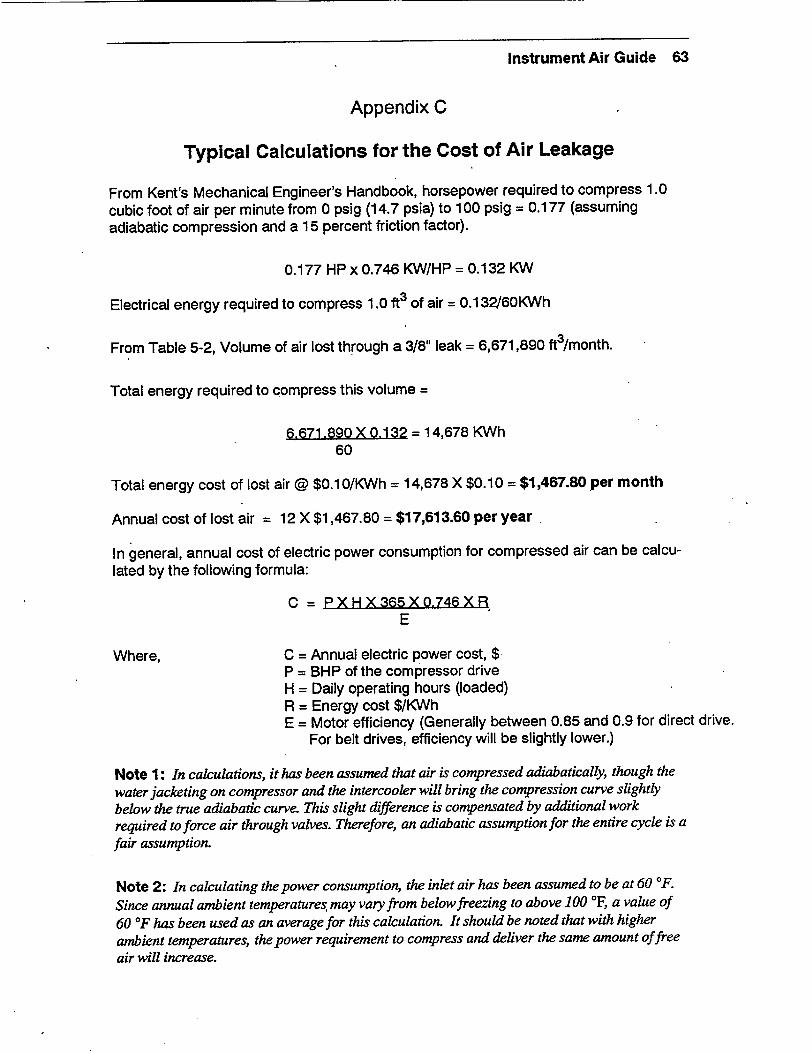
Instrument Air Guide 63
Appendix C
Typical Calculations for the Cost of Air Leakage
From Kent's Mechanical Engineer's Handbook, horsepower required to compress 1.0 cubic foot of air per minute from 0 psig (14.7 psia) to 100 psig = 0.177 (assuming adiabatic compression and a 15 percent friction factor).
0.177 HP x 0.746 KW/HP = 0.132 KW
Electrical energy required to compress 1.0 ft3 of air = 0.132_6OKWh
From Table 5-2, Volume of air lost through a 3/8" leak = 6,671,890 ft3/month.
Total energy required to compress this volume =
6,671.890 X 0.132 = 14,678 KWh 60
Total energy cost of lost air @ $0.10/KWh = 14,678 X $0.10 = $1,467.80 per month
Annual cost of lost air = 12 X $1,467.80 = $17,613.60 per year
In general, annual cost of electric power consumption for compressed air can be calculated by the following formula:
C = PXHX365XO.746XR E
Where, C = Annual electric power cost, $ P = BHP of the compressor drive H = Daily operating hours (loaded) R = Energy cost $/KWh E = Motor efficiency (Generally between 0.85 and 0.9 for direct drive.
For belt drives, efficiency will be slightly lower.)
Note 1: In calculations, it has been assumed that air is compressed adiabatically, though the water jacketing on compressor and the intercooler will bring the compression curve slightly below the true adiabatic curve. This slight difference is compensated by additional work required to force air through valves. Therefore, an adiabatic assumption for the entire cycle is a fair assumption.
Note 2: In calculating the power consumption, the inlet air has been assumed to be at 60 YF. Since annual ambient temperatures, may vary from below freezing to above 100 °F, a value of 60 YF has been used as an average for this calculation. It should be noted that with higher ambient temperatures, the power requirement to compress and deliver the same amount of free air will increase.

Instrument Air Guide 65
Appendix D
Sample Calculation for Free Air Volume
From the ideal gas law,
P1VI = P2V2
Ti T2
Where, Pi = Initial Pressure, psia P2 = Final Pressure, psia V1 = Initial Volume, Ft3
V2 = Final Volume, Ft3
Ti = Initial Temperature, OR "T2 = Final Temperature, 'R tj = Initial Temperature, °F t2 = Final Temperature, 'F
In the example on Page 9 of this guide,
P1 = P2, since suction and discharge are at atmospheric pressure.
Ti = (ti + 460°F) = (40'F + 460'F) = 500*R
"T2 = (t2 + 460*F) = (80°F + 460'F) = 540°R
V2 = 1000 Ft3
Therefore,
V1 = V2Ti = 1000X500 = 926 Ft3
T2 540
This represents a savings of:
1000-926 X 100=7.4% 1000

Instrument Air Guide 67
Appendix E
GLOSSARY
Absorb - To suck up or takeup (i.e., sponge taking up water).
Accumulators - One that accumulates. Used in compressed air systems to provide additional storage volume for the air system.
Adsorb - The adhesion of an extremely thin layer of molecules to the surfaces of solid bodies or liquids with which they are in contact.
Aftercoolers - Heat exchangers for cooling air or gas discharged from compressors.
Afterfilters - Filters installed in an air system which are downstream of the air dryers.
Air Cooled Compressors - Air compressors which are cooled by atmospheric air circulated around the cylinders or casings.
BOD - Baseline operating data.
Capacity - The capacity of a compressor is the full rated volume of flow of gas compressed and delivered at conditions of total temperature, total pressure, and composition prevailing at the compressor inlet. It sometimes means actual flow rate, rather than rated volume of flow.
Coalescing Filter - A filter which collects water and oil mist, combines it into larger droplets, and allows them to drain to the bottom of the cartridge housing where they can be. removed via a drain trap or blowdown valve.
Compression, Adiabatic - This type of compression is effected when no heat is transferred to or from the gas during the compression process.
Compression, Isothermal - A compression in which the temperature of the gas remains constant. For perfect gases, it is represented by the equation PV is a constant, if the process is reversible.
Compression, Polytropic - Compression in which the relationship between the pressure and the volume is expressed by the equation PVn is a constant.
Compression Ratio - The ratio of the absolute discharge pressure to the absolute inlet pressure.
Compressor - A mechanical device that takes successive volumes of air or gas within a closed space and increases the pressure by reducing the volume of the space.
Desiccant - A material that is capable of removing water vapor from the air.
Dewpoint - The temperature at which a given volume of air is saturated with water vapor. Decreasing the temperature or raising the pressure results in condensation.
Dynamic, Compressors - Machines in which air or gas is compressed by the mechanical action of rotating vanes or impellers imparting velocity and pressure to the flowing medium.
Filters - Devices for separating and removing dust, dirt, or other particulate from the air.

Instrument Air Guide 68
Free Air - Air at atmospericconditions at any specific location. Because the altitude, barometric pressure, and temperature may vary at different localities, and at different times, it follows that this term does not mean air under identical or standard conditions.
Humidity, Relative - The ratio of the partial pressure of the vapor to the vapor saturation pressure at the dry bulb temperature of the mixture.
Humidity, Specific - The weight of the water vapor in air vapor mixture per pound of dry air. Impeller - The part of the rotating element of a dynamic compressor that imparts energy to the flowing medium by means of centrifugal force. It consists of a number of blades mounted so as to rotate with the shift.
Intercoolers - Heat exchangers for removing the heat of compression between stages of compression on a compressor. They also condense and remove moisture from the compressed air.
Intercooling - The removal of heat from the air between stages of a compressor.
Liquid Piston Compressor - A rotary compressor in which a vaned rotor revolved in an
eliptical casing, with the rotor spaces sealed by a ring of liquid rotating with it inside the casing.
Moisture Separator - A device which removes liquids from the air stream.
Multistage Compressor - Machine employing two or more compression stages.
Prefilter - A filter which precedes the compressed air dryer for the protection of the desiccant or heat transfer surfaces.
Prefilter, Coalescing - A prefilter that removes water and oil aerosols by combining the aerosols into larger droplets for easy removal.
Pressure, Absolute - The total pressure measured from absolute zero (i.e., from an absolute vacuum). It equals the sum of the gage pressure and the atmospheric pressure corresponding to the barometer
Pressure, Discharge - The absolute total pressure at the discharge flange of a compressor.
Pressure, Intake - The absolute total pressure at the intake flange of a compressor.
Receivers - Tanks used for the storage of air discharged from compressors. They also serve to dampen discharge line pulsations.
Reciprocating Compressors - Machines in which the compressing element is a piston having a reciprocating motion inside a cylinder.
Single Stage Compressor - Machines in which the air is compressed from intake pressure to discharge pressure in a single compression stage.
Tedlar Bag -Single Stage Centrifugal Compressor - Machine having only one impeller.
Speed of the Compressor - The number of revolutions per minute of the compressor shaft.
Stages - Steps in the compression cycle of a gas.
Standard Air - Air at a temperature of 680F, a pressure of 14.7 psia, and a relative humid
ity of 36 percent. This is in agreement with definitions adopted by ASME, but in gas
industries, the temperature of "standard air" is usually given at 600 F.
Instrument Air Guide 69
Appendix F
Compressed Air Safety
The following questions are designed to aid power plant personnel in determining if proper safety measures have been taken in the installation and operation of their compressed air systems. If answers to any of the following questions is "no", the work conditions should be thoroughly reviewed from the work safety point of view. They are based on Cal/OSHA Standards and are general in nature.
COMPRESSORS AND COMPRESSED AIR
"* Are compressors equipped with automatic, temperature-activated shutoff mechanisms, or with fusible plugs installed in the compressor discharge lines as near the compressor as possible?
"* Are compressors equipped with automatic pressure release valves, pressure gages, and drain valves?
"* Are compressor air intakes installed and equipped so as to ensure that only clean uncontaminated air enters the compressor?
"* Are air filters installed on the compressor intake? "* Are compressors operated and lubricated in accordance with the manufacturer's rec
ommendations? "* Are safety devices on compressed air systems checked frequently? "* Before any repair work is done on the pressure system of a compressor, is the pres
sure bled off and the system locked-out? "* Are signs posted to warn of the automatic starting feature of the compressors? "* Is the belt drive system totally enclosed to provide protection for the front, back, top,
and sides? "* Is it strictly prohibited to direct compressed air towards a person? * Are employees prohibited from using highly compressed air (100 psig) for cleaning
purposes? * If compressed air is used for cleaning off clothing, is the pressure reduced to less
than 10 psi? * When using compressed air for cleaning, do employees wear protective chip guard
ing and personal protective equipment? * Are safety chains or other suitable locking devices used at couplings of all high pres
sure hose lines of 3/4 inch inside diameter or larger, and lines of smaller size, where a connection failure would create a hazard?
"* Before compressed air is used to empty containers of liquid, is the safe working pressure of the container checked?
"* When compressed air is used with abrasive blast cleaning equipment, is the operating valve a type that must be held open manually?
"* When compressed air is used to inflate auto tires, is a clip-on chuck and an inline regulator preset to 40 psi required?

Instrument Air Guide 70
* Is it prohibited to use compressed air to clean up or move combustible dust if such action could cause the dust to be suspended in the air and cause a fire or explosion hazard?
COMPRESSED AIR RECEIVERS
Is every receiver equipped with a pressure gage and with one or more automatic, spring-loaded safety valves? Is the total relieving capacity of the safety valve capable of preventing pressure in the receiver from exceeding the maximum allowable working pressure of the receiver by more than 10 percent?
Is every air receiver provided with a drain pipe and valve at the lowest point for the ,removal of accumulated oil and water?
"* Are compressed air receivers periodically drained of moisture and oil? "* Does each compressed air receiver have an inspection opening for internal inspec
tions? "* Are all air receivers periodically inspected externally for corrosion, dents, etc.? "* Are all safety valves tested frequently and at regular intervals to determine whether
they are in good operating condition? " Is each compressed air receiver inspected internally at least once a year by a quali
fied inspector? "* Are the external surfaces of air receivers kept free of oil and dust accumulation? * Is the inlet of air receivers and piping systems kept free of accumulated oil and car
bonaceous materials? Have the following safety precautions been incorporated into the procedures for the internal inspection of air receivers?
- Is all starting and control equipment tagged and locked-out? - Is the air pressure released from the vessel? - Are externally bolted manhole covers first pried loose from their seats before en
tirely removing all of the bolts or nuts? - Are all manhole covers removed to improve ventilation? - Is tank atmosphere tested for oxygen, carbon dioxide concentrations, and toxic,
flammable, or combustible gases and vapors before employees are permitted to enter the tank?
- If a hazardous atmosphere is present, is respiratory equipment required to be used (supplied-air type)?
- Are employees entering the tank required to be equipped with a lifeline, and a safety watcher positioned at the tank opening?
- Are employees required to wear proper eye, face, hand,and foot protection to prevent injuries?
- Are portable electric lamps or tools, used inside the - tank explosion-proof and grounded? - After cleaning, is the inside inspected for loose scale, wiping rags, tools, or pieces
of lint? - Are new gaskets placed on the manhole covers?

NMIVAC
NP-7079


