100
Instrument Transformers Instrument Transformer Basics Application & Selection
Instrument Transformers
Instrument Transformer BasicsApplication & Selection

GE Digital Energy
GE - XD High Voltage Instrument Transformers
What Is An Instrument Transformer?
Instrument Transformers are used to scale down the voltage or current to a standardized value when voltage or current is too large to be conveniently used by a measurement, protection, or control instrument.
• CT’s: Current Transformers• VT’s: Voltage transformers, also referred to as "potential transformers"
(PT’s)
GE Instrument Transformers
GE Digital Energy
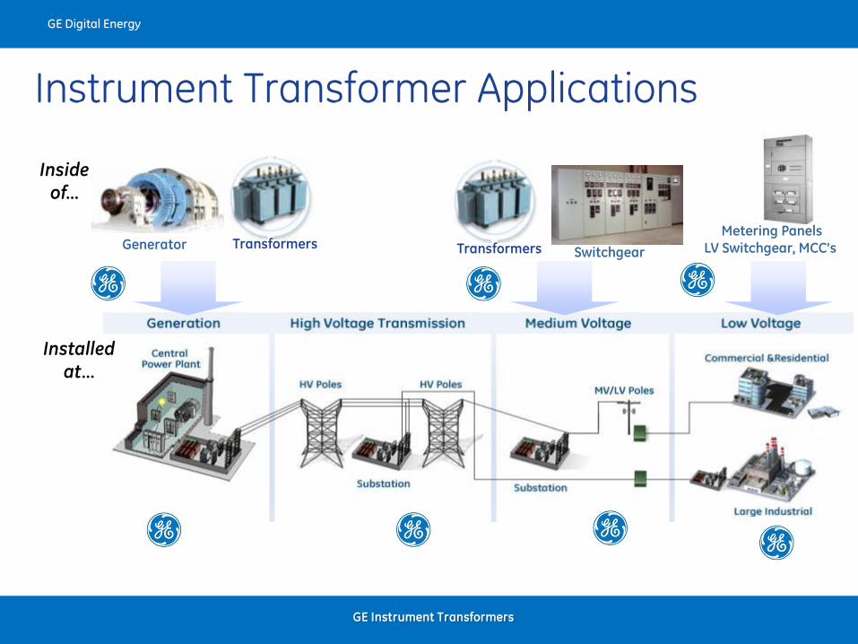
Inside
of…
Switchgear
Metering PanelsLV Switchgear, MCC’s
Installed
at…
Generator TransformersTransformers
Instrument Transformer Applications
GE Instrument Transformers
GE Digital Energy
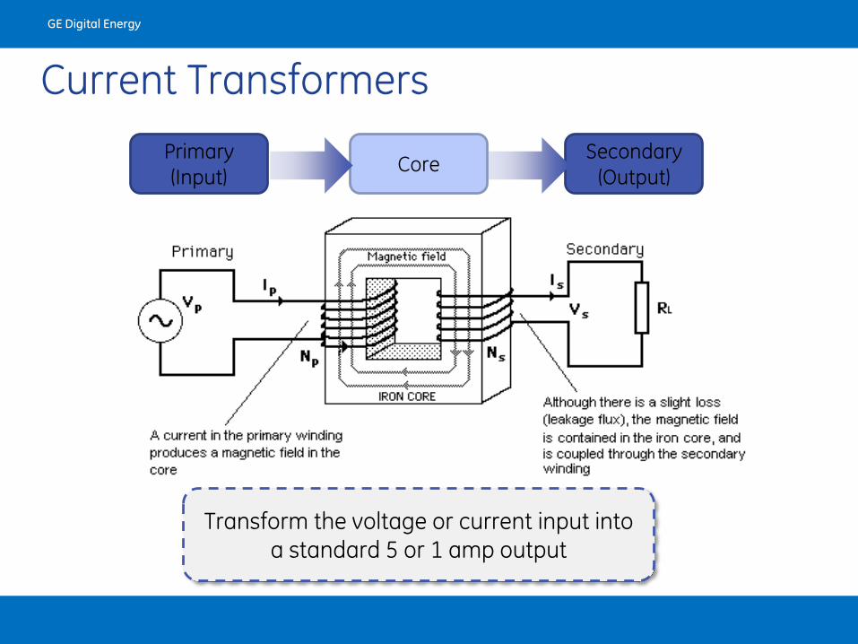
Secondary(Output)
Current Transformers
Primary(Input)
Core
Transform the voltage or current input into a standard 5 or 1 amp output
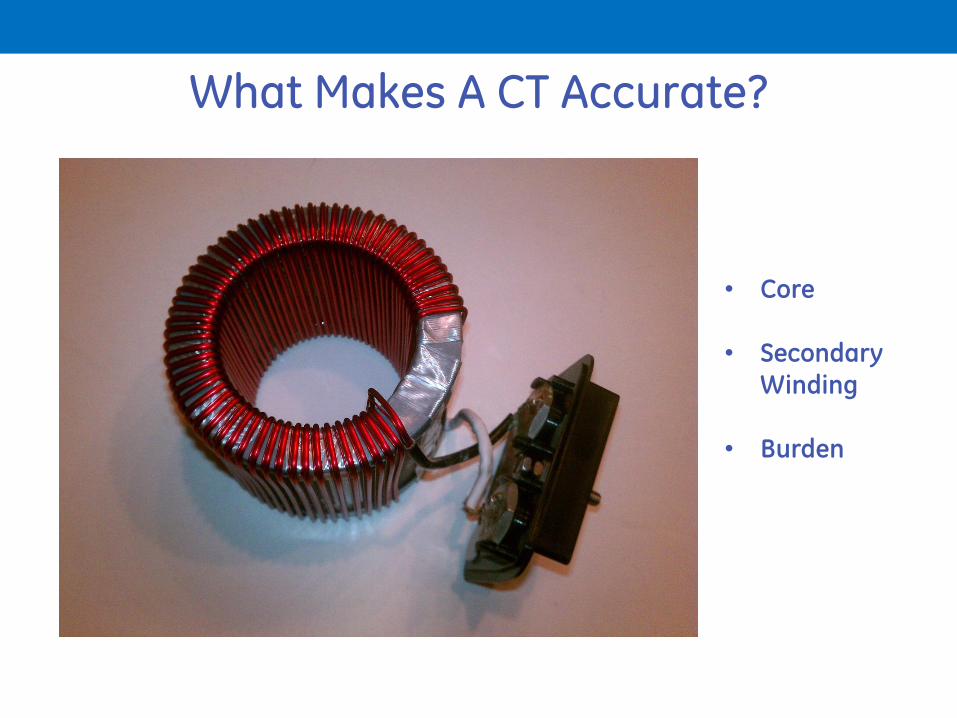
What Makes A CT Accurate?
• Core
• Secondary Winding
• Burden
GE Instrument Transformers
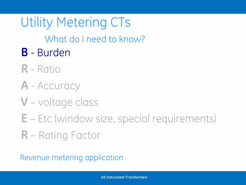
Utility Metering CTsWhat do I need to know?
B - Burden
R - Ratio
A - Accuracy
V – voltage class
E – Etc (window size, special requirements)
R – Rating Factor
Revenue metering application
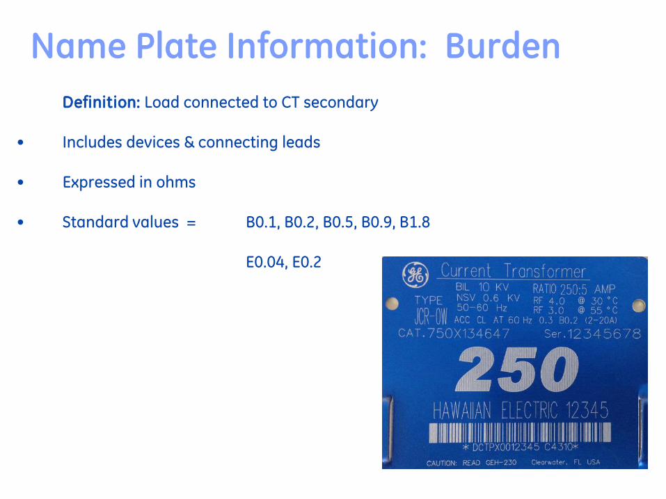
Name Plate Information: Burden
Definition: Load connected to CT secondary
• Includes devices & connecting leads
• Expressed in ohms
• Standard values = B0.1, B0.2, B0.5, B0.9, B1.8
E0.04, E0.2

Application Burden
Designation
Impedance
(Ohms)
VA @
5 amps
Power
Factor
Metering B0.1 0.1 2.5 0.9
B0.2 0.2 5 0.9
B0.5 0.5 12.5 0.9
B0.9 0.9 22.5 0.9
B1.8 1.8 45 0.9
Standard IEEE CT Burdens (5 Amp)
(Per IEEE Std. C57.13-1993 & C57.13.6)
Standard Burdens
E0.2
E0.04
0.2
0.04
5
11.0
1.0
GE Instrument Transformers

VT Burden
ANSI
Designation
VA Power
Factor
W 12.5 0.10
X 25.0 0.70
M 35.0 0.20
Y 75.0 0.85
Z 200.0 0.85
GE Instrument Transformers
What’s the difference between a Y VA rating and a Thermal VA rating?
GE Instrument Transformers
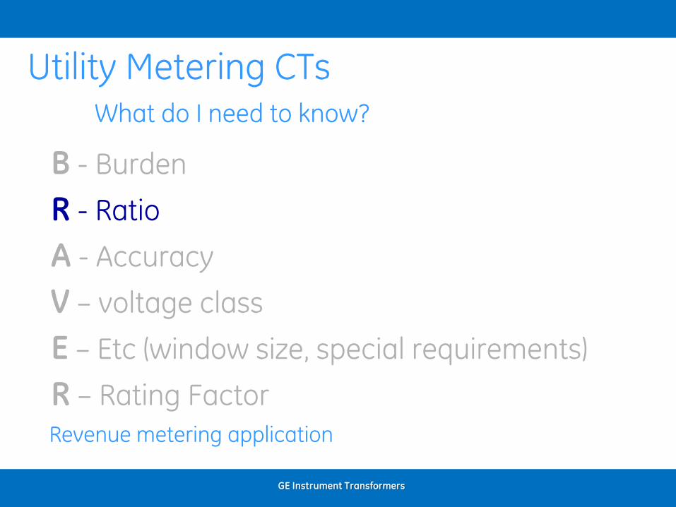
Utility Metering CTsWhat do I need to know?
B - Burden
R - Ratio
A - Accuracy
V – voltage class
E – Etc (window size, special requirements)
R – Rating Factor
Revenue metering application
GE ITI/
August 13, 2017Private & Confidential, not for distribution. If the reader of this presentation is not the intended person or entity, you are notified that
any unauthorized distribution, reproduction or use of this communication is strictly prohibited
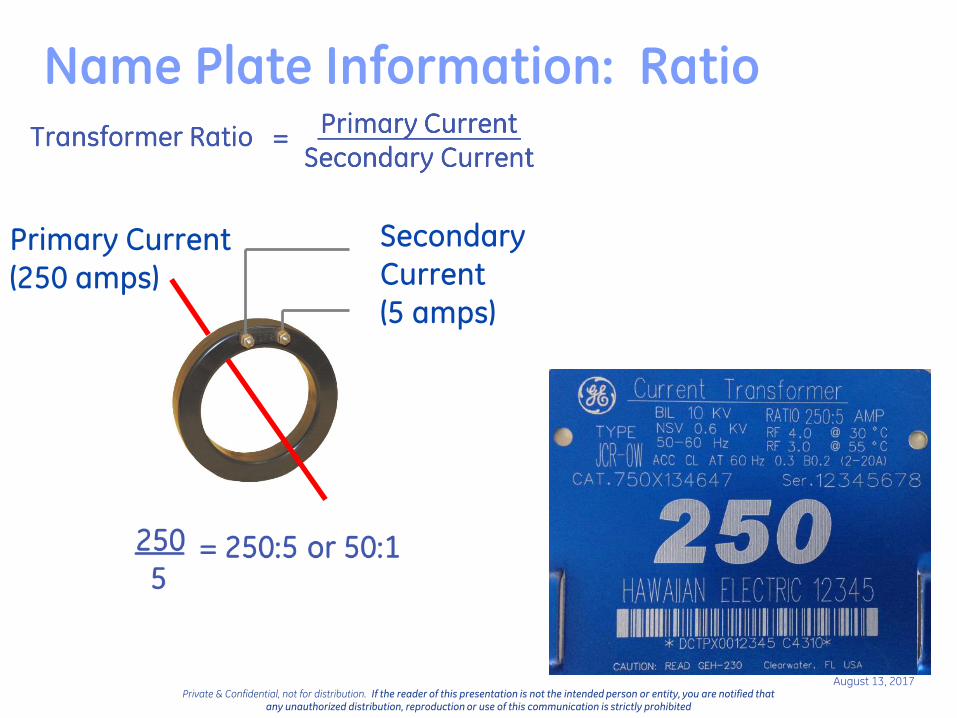
Name Plate Information: Ratio
Primary Current(250 amps)
Secondary Current (5 amps)

Transformer ratio (TR)
Use as a 200:5 with one primary conductor turn
Use as a 100:5 with two primary conductor turns
Use as a 50:5 with four primary conductor turns
Remember: Ip = Is x Ns/Np
Example: Window CT wound as a 200:5

Wound type CTMV Primary Winding
Higher primary turns, means lower ratios are possible while maintaining accuracy.

Secondary Turn Ratio Method:
Turns Ratio Modification:
GE Instrument Transformers

GE ITI/
August 13, 2017Private & Confidential, not for distribution. If the reader of this presentation is not the intended person or entity, you are notified that
any unauthorized distribution, reproduction or use of this communication is strictly prohibited
Polarity
> H1 primary terminals are usually connected on the line side of circuit.
> X1 secondary terminals are usually connected to the meter, not to ground.
H1 H2
X1 X2
> If at an instant, primary current is entering H1, then secondary current will be leaving X1.
Polarity Marking
> Polarity Marks are used in diagrams and on transformers to show which terminals are H1, X1, or Y1. These marks are dots that contrast with the background.

GE ITI/
August 13, 2017Private & Confidential, not for distribution. If the reader of this presentation is not the intended person or entity, you are notified that
any unauthorized distribution, reproduction or use of this communication is strictly prohibited
Polarity
Direction ofPrimary Current
Direction of Secondary Current
H1
X1
Primary current into “polarity” =
Secondary current out of “polarity”
Primary PolarityMarks
Secondary PolarityMarks
Remember:

GE ITI/
August 13, 2017Private & Confidential, not for distribution. If the reader of this presentation is not the intended person or entity, you are notified that
any unauthorized distribution, reproduction or use of this communication is strictly prohibited
Polarity
Direction ofPrimary Current
Direction of Secondary Current
H1
X1
Primary PolarityMarks
Secondary PolarityMarks
Primary current into “non-polarity” =
Secondary current out of “non-polarity”
Remember:

GE Instrument Transformers
Utility Metering CTsWhat do I need to know?
B - Burden
R - Ratio
A - Accuracy
V – voltage class
E – Etc (window size, special requirements)
R – Rating Factor
Revenue metering application


CT Metering Accuracy
Actual secondary current
Rated secondary current=
Difference in % is known as the “Accuracy”
of the CT
Definition: There are two sources of error in instrument transformers, namely ratio error and phase angle
error. In a given transformer, the metering error is the combination of the two separate errors. This
combination is called Transformer Correction Factor (TCF), IEEE has established accuracy classes for both
current and potential transformers. The limit of permissible error in a potential transformer for a given
accuracy class remains constant over a range of voltage from 10% below to 10% above rated voltage
GE Instrument Transformers

GE ITI/
August 13, 2017Private & Confidential, not for distribution. If the reader of this presentation is not the intended person or entity, you are notified that
any unauthorized distribution, reproduction or use of this communication is strictly prohibited
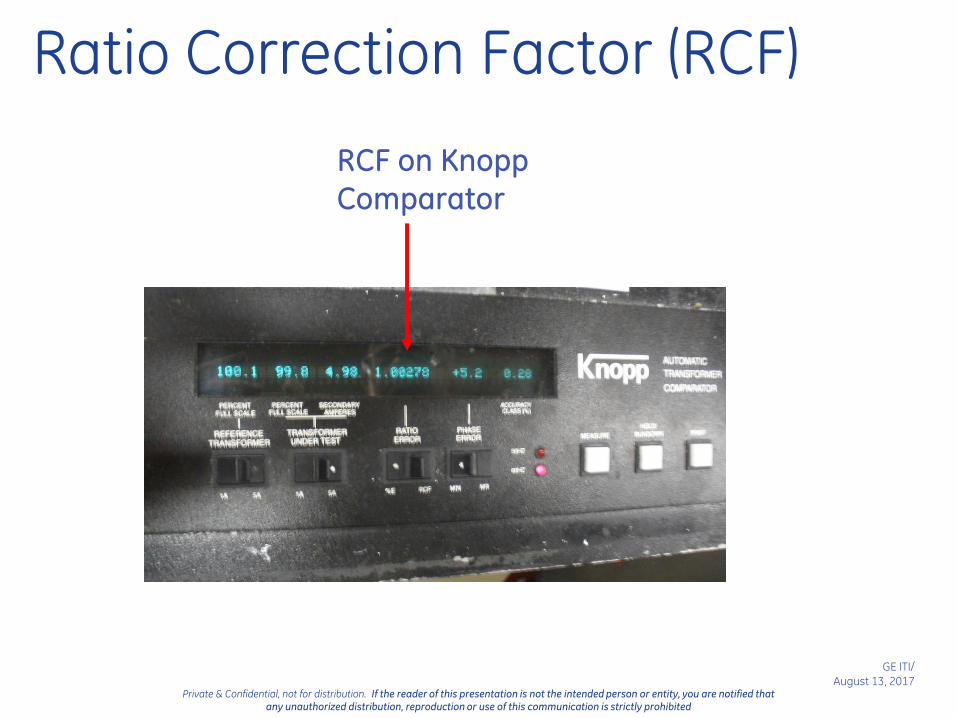
Ratio Correction Factor (RCF)
IEEE C57.13 Terminology
RCF = True Ratio / Marked Ratio
Example: 500:5 CT
By test, CT Ratio = 100.1
RCF = 100.1 / 100 = 1.0010
What does this mean? How many amps is the meter
seeing?
A. – With 500A through primary, only 4.995A is
flowing on the secondary 4.995 x 1.001 = 5A.
(Negative current error due to losses)
GE ITI/
August 13, 2017Private & Confidential, not for distribution. If the reader of this presentation is not the intended person or entity, you are notified that
any unauthorized distribution, reproduction or use of this communication is strictly prohibited
Ratio Correction Factor (RCF)
RCF on Knopp Comparator
GE ITI/
August 13, 2017Private & Confidential, not for distribution. If the reader of this presentation is not the intended person or entity, you are notified that
any unauthorized distribution, reproduction or use of this communication is strictly prohibited
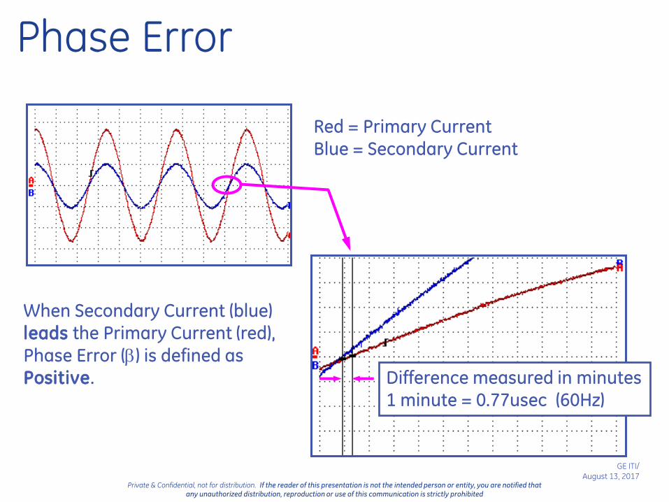
Phase Error
Red = Primary CurrentBlue = Secondary Current
When Secondary Current (blue) leads the Primary Current (red),
Phase Error () is defined as Positive. Difference measured in minutes
1 minute = 0.77usec (60Hz)

GE ITI/
August 13, 2017Private & Confidential, not for distribution. If the reader of this presentation is not the intended person or entity, you are notified that
any unauthorized distribution, reproduction or use of this communication is strictly prohibited
Phase Error
Phase Error on Knopp Comparator

GE ITI/
August 13, 2017Private & Confidential, not for distribution. If the reader of this presentation is not the intended person or entity, you are notified that
any unauthorized distribution, reproduction or use of this communication is strictly prohibited
IEEE Std. C57.13 limits of accuracy class for currenttransformers for metering 0.3 accuracy class
CT PARALLELOGRAM
Recall the Knopp
Comparator
The values were:
• Ratio Error = 1.00278
• Φ Angle Error = 5.2

GE ITI/
August 13, 2017Private & Confidential, not for distribution. If the reader of this presentation is not the intended person or entity, you are notified that
any unauthorized distribution, reproduction or use of this communication is strictly prohibited
Courtesy of Electric Power Transformer Handbook
Energy Required to Energize the Core
Secondary turns or core cross section
secondary impedanceIf energy required to energize coreThen

Graph: Bill Hardy – TEC PowerMetrix
GE Instrument Transformers
Core energy needed Saturation
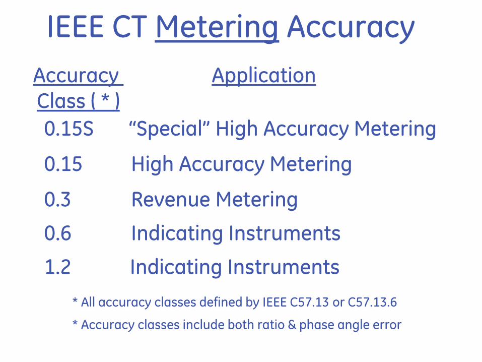
IEEE CT Metering Accuracy
Accuracy Class ( * )
Application
0.15S “Special” High Accuracy Metering
0.15 High Accuracy Metering
0.3 Revenue Metering
0.6 Indicating Instruments
1.2 Indicating Instruments
* All accuracy classes defined by IEEE C57.13 or C57.13.6
* Accuracy classes include both ratio & phase angle error

GE ITI/
August 13, 2017Private & Confidential, not for distribution. If the reader of this presentation is not the intended person or entity, you are notified that
any unauthorized distribution, reproduction or use of this communication is strictly prohibited
0.9940
0.9950
0.9960
0.9970
0.9980
0.9990
1.0000
1.0010
1.0020
1.0030
1.0040
1.0050
1.0060
-32.0 -28.0 -24.0 -20.0 -16.0 -12.0 -8.0 -4.0 0.0 4.0 8.0 12.0 16.0 20.0 24.0 28.0 32.0
0.6 Accuracy
0.15 Accuracy
0.3 Accuracy
CT PARALLELOGRAMIEEE C57.13 – Accuracy Limits
Rati
o C
orr
ecti
on
Facto
r (R
CF
)
Phase Angle, minutes
Lagging Leading
Accuracy Class Definitions

GE ITI/
August 13, 2017Private & Confidential, not for distribution. If the reader of this presentation is not the intended person or entity, you are notified that
any unauthorized distribution, reproduction or use of this communication is strictly prohibited
IEEE CT Metering Accuracy
Example 1:
0.3 accuracy CT, 200:5, RF 4.0 (Standard)
200 amps (rated amps) to 800 amps (RF 4.0) = 0.3% accuracy
20 amps (10% of rated amps) to 200 amps (rated amps) = 0.6%

Private & Confidential, not for distribution. If the reader of this presentation is not the intended person or entity, you are notified that any unauthorized distribution, reproduction or use of this communication is strictly prohibited
0.30
0.30
0.60
0.60
Rating Factor
Ac
cura
cy
Cla
ss -
%
10%
1.0 RF
IEEE C57.13 Accuracy0.3 @ BX.X; RF = X.X
±0.3% Accuracyfrom 100% rated
current up to RF
100%
Standard 0.3 Accuracy Class±0.6% Accuracy
from 10% to 100% of rated current
No accuracy guaranteed at current levels less than 10%
Typical 0.3 CT Performance Curve

GE ITI/
August 13, 2017Private & Confidential, not for distribution. If the reader of this presentation is not the intended person or entity, you are notified that
any unauthorized distribution, reproduction or use of this communication is strictly prohibited
IEEE CT Metering Accuracy
Example 2:
0.3 accuracy CT, 500:5, RF 0.4 - 4.0 (Encompass)
200 amps (40% of rated amps) to 2000 amps (RF 4.0) = 0.3% accuracy
20 amps (4% of rated amps) to 200 amps ( 40% of rated amps) = 0.6% accuracy

Private & Confidential, not for distribution. If the reader of this presentation is not the intended person or entity, you are notified that any unauthorized distribution, reproduction or use of this communication is strictly prohibited
0.30
0.30
0.60
0.60
Rating Factor
Ac
cura
cy
Cla
ss -
%
4% 100%
1.0
“Stretching” the rating factor0.30 @ BX.X; RF 0.4-X.X
0.15
0.15
.4
40%
ITI Encompass
RF
±0.3% Accuracyfrom 40% rated
current up to RF
±0.6% Accuracyfrom 4% to 40% of rated current
Typical EncompassPerformance Curve
GE ITI/
August 13, 2017Private & Confidential, not for distribution. If the reader of this presentation is not the intended person or entity, you are notified that
any unauthorized distribution, reproduction or use of this communication is strictly prohibited
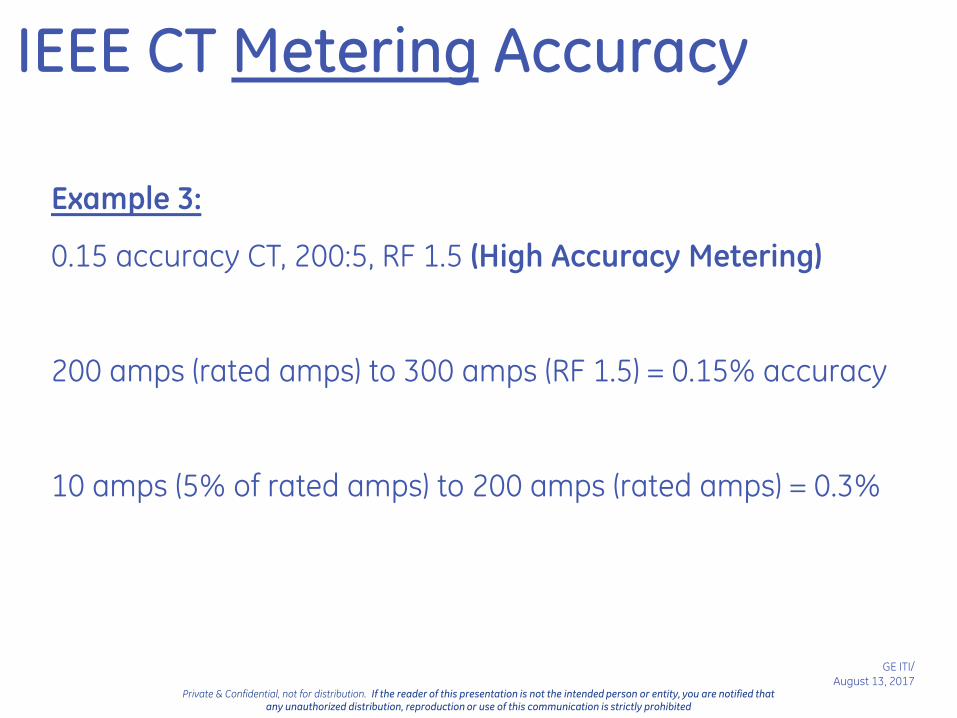
IEEE CT Metering Accuracy
Example 3:
0.15 accuracy CT, 200:5, RF 1.5 (High Accuracy Metering)
200 amps (rated amps) to 300 amps (RF 1.5) = 0.15% accuracy
10 amps (5% of rated amps) to 200 amps (rated amps) = 0.3%

Private & Confidential, not for distribution. If the reader of this presentation is not the intended person or entity, you are notified that any unauthorized distribution, reproduction or use of this communication is strictly prohibited
0.30
0.30
0.60
0.60
Rating Factor
Ac
cura
cy
Cla
ss -
%
5%
1.0
±0.15% Accuracyfrom 100% up to RF
100%
0.15 High Accuracy Class
±0.3% Acc. from 5% - 100%
0.15
0.15
IEEE C57.13.6 Accuracy0.15 @ BX.X; RF = X.X
Typical 0.15 CT Performance Curve
No accuracy guaranteed at current levels less than 5%
RF

GE ITI/
August 13, 2017Private & Confidential, not for distribution. If the reader of this presentation is not the intended person or entity, you are notified that
any unauthorized distribution, reproduction or use of this communication is strictly prohibited
IEEE CT Metering Accuracy
Example 4: (Accubute)
0.15S accuracy CT, 200:5, RF 1.5 (Special High Accuracy Metering)
10 amps (5% of rated amps) – 300 amps (rated amps) = 0.15%

Private & Confidential, not for distribution. If the reader of this presentation is not the intended person or entity, you are notified that any unauthorized distribution, reproduction or use of this communication is strictly prohibited
0.30
0.30
0.60
0.60
Rating Factor
Ac
cura
cy
Cla
ss -
%
100%
1.0
0.15
0.15
0.15S Special High Accuracy (Accubute)IEEE C57.13.6 Accuracy
0.15 @ E0.04, E0.20; 0.15 @ BX.X; RFX.X
5%
±0.15% Accuracyfrom 5% up to RF
Typical CT Accubute™ Performance Curve
No accuracy guaranteed at current levels less than 5%
RF
GE ITI/
August 13, 2017Private & Confidential, not for distribution. If the reader of this presentation is not the intended person or entity, you are notified that
any unauthorized distribution, reproduction or use of this communication is strictly prohibited
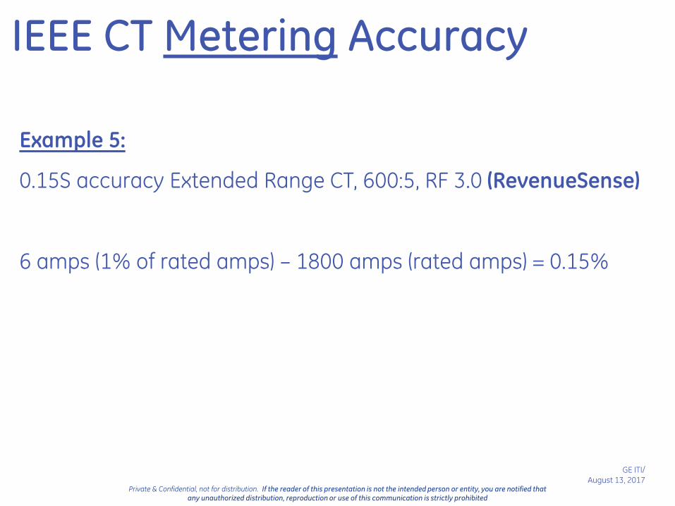
IEEE CT Metering Accuracy
Example 5:
0.15S accuracy Extended Range CT, 600:5, RF 3.0 (RevenueSense)
6 amps (1% of rated amps) – 1800 amps (rated amps) = 0.15%
Private & Confidential, not for distribution. If the reader of this presentation is not the intended person or entity, you are notified that any unauthorized distribution, reproduction or use of this communication is strictly prohibited
0.30
0.30
0.60
0.60
Rating Factor
Ac
cura
cy
Cla
ss -
%
100%
1.0
0.15
0.15
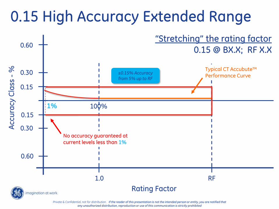
0.15 High Accuracy Extended Range
1%
±0.15% Accuracyfrom 5% up to RF
Typical CT Accubute™ Performance Curve
No accuracy guaranteed at current levels less than 1%
RF
“Stretching” the rating factor0.15 @ BX.X; RF X.X

Private & Confidential, not for distribution. If the reader of this presentation is not the intended person or entity, you are notified that any unauthorized distribution, reproduction or use of this communication is strictly prohibited
DefinitionsStandard Revenue Metering Accuracy (IEEE 0.3 Accuracy Class)
± 0.3% accurate from 100% Nameplate Rating, up to Rating Factor
± 0.6% accurate below 100% Nameplate Rating, down to 10% of Nameplate Rating
GE ITI Encompass CT’s
± 0.3% accurate from 40% of Nameplate Rating, up to Rating Factor
± 0.6% accurate below 40% Nameplate Rating down to 4% of Nameplate Rating
High Accuracy (IEEE 0.15 Accuracy Class)
± 0.15% accurate from 100% Nameplate Rating, up to Rating Factor
± 0.3% accurate below 100% Nameplate Rating, down to 5% of Nameplate Rating
GE Somersworth Accubute™ (IEEE 0.15S Accuracy Class)
± 0.15% accurate from down to 5% of Nameplate Rating, up to Rating Factor
GE RevenueSense High Accuracy Extended Range (IEEE 0.15S Accuracy Class)
± 0.15% accurate from down to 1% of Nameplate Rating, up to Rating Factor

Private & Confidential, not for distribution. If the reader of this presentation is not the intended person or entity, you are notified that any unauthorized distribution, reproduction or use of this communication is strictly prohibited

IEEE VT Accuracy Class
Metering Accuracy Classes (% error)
0.3
0.6
1.2
0.15
Defined by IEEE C57.13
Applicable from 90% to 110% rated voltage
Defined by IEEE C57.13.6

VT Accuracy/Burden Designation
Expressed as:
Accuracy Class + Burden Code
0.3 W,X,Y0.6 Z
1.2 ZZ
Means 0.3 class up to a 75 VA burden
GE ITI/
August 13, 2017Private & Confidential, not for distribution. If the reader of this presentation is not the intended person or entity, you are notified that
any unauthorized distribution, reproduction or use of this communication is strictly prohibited
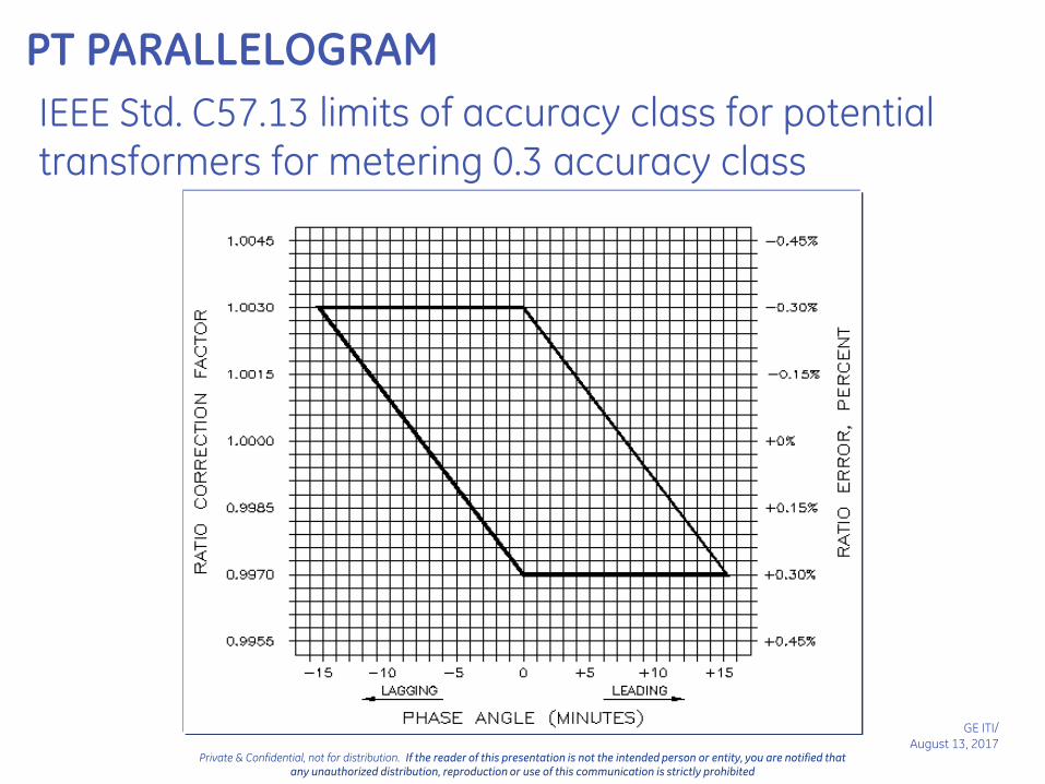
PT PARALLELOGRAM
IEEE Std. C57.13 limits of accuracy class for potential
transformers for metering 0.3 accuracy class

VT 0.3 Accuracy Class
Load line is drawn between zero and full burden points.
Accuracy changes linearly with burden.
Higher burden rating does not automatically mean better accuracy performance.

VT Load Line 0.3 WXYZ

VT Load Line 0.3 WXY

Utility Metering CTsWhat do I need to know?
B - Burden
R - Ratio
A - Accuracy
V – voltage class
E – Etc (window size, special requirements)
R – Rating Factor
Revenue metering application
GE Instrument Transformers
GE ITI/
August 13, 2017Private & Confidential, not for distribution. If the reader of this presentation is not the intended person or entity, you are notified that
any unauthorized distribution, reproduction or use of this communication is strictly prohibited
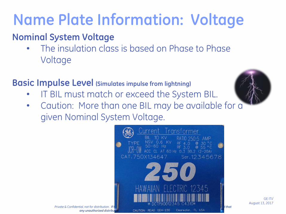
Name Plate Information: VoltageNominal System Voltage
• The insulation class is based on Phase to Phase Voltage
Basic Impulse Level (Simulates impulse from lightning)
• IT BIL must match or exceed the System BIL.• Caution: More than one BIL may be available for a
given Nominal System Voltage.

Standard Voltage Classes
Insulation Class(IEEE C57.13)
Class Power Freq. BIL
0.6kV 4kV 10kV
5kV 19kV 60kV
8.7kV 26kV 75kV
15kV 34kV 95-110kV
25kV 40-50kV 125-150kV
34.5kV 70kV 200kV
Insulation class should at least equal maximum Line-Line voltage at the point of connection.
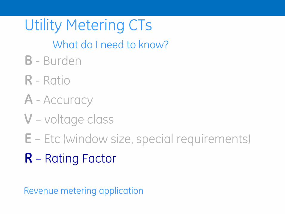
Utility Metering CTsWhat do I need to know?
B - Burden
R - Ratio
A - Accuracy
V – voltage class
E – Etc (window size, special requirements)
R – Rating Factor
Revenue metering application

Name Plate Information: Rating Factor
Rated current x (RF) = Maximum continuous current carrying capability:
• Without exceeding temperature limits
• Without loss of published accuracy class
Typical rating factors -- 1.0, 1.33, 1.5, 2.0, 3.0, 4.0
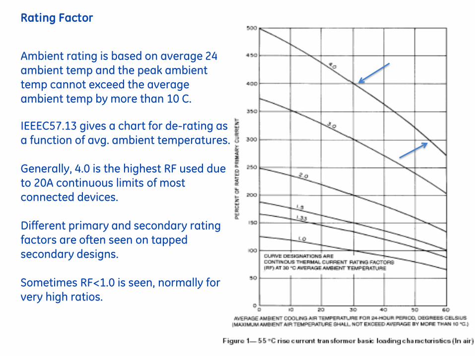
Rating Factor
Ambient rating is based on average 24hr ambient temp and the peak ambient temp cannot exceed the average ambient temp by more than 10 C.
IEEEC57.13 gives a chart for de-rating as a function of avg. ambient temperatures.
Generally, 4.0 is the highest RF used due to 20A continuous limits of most connected devices.
Different primary and secondary rating factors are often seen on tapped secondary designs.
Sometimes RF<1.0 is seen, normally for very high ratios.
GE ITI/
August 13, 2017Private & Confidential, not for distribution. If the reader of this presentation is not the intended person or entity, you are notified that
any unauthorized distribution, reproduction or use of this communication is strictly prohibited
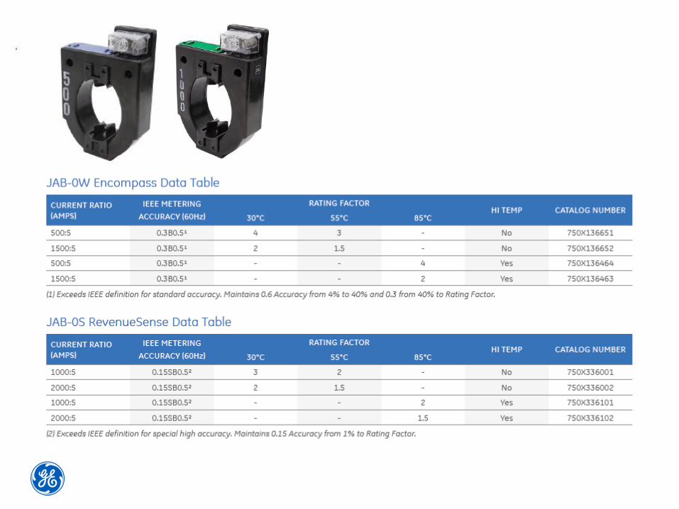
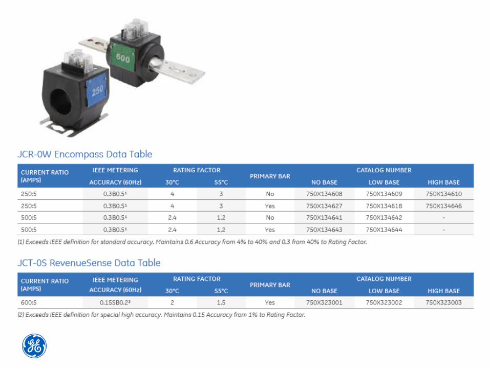
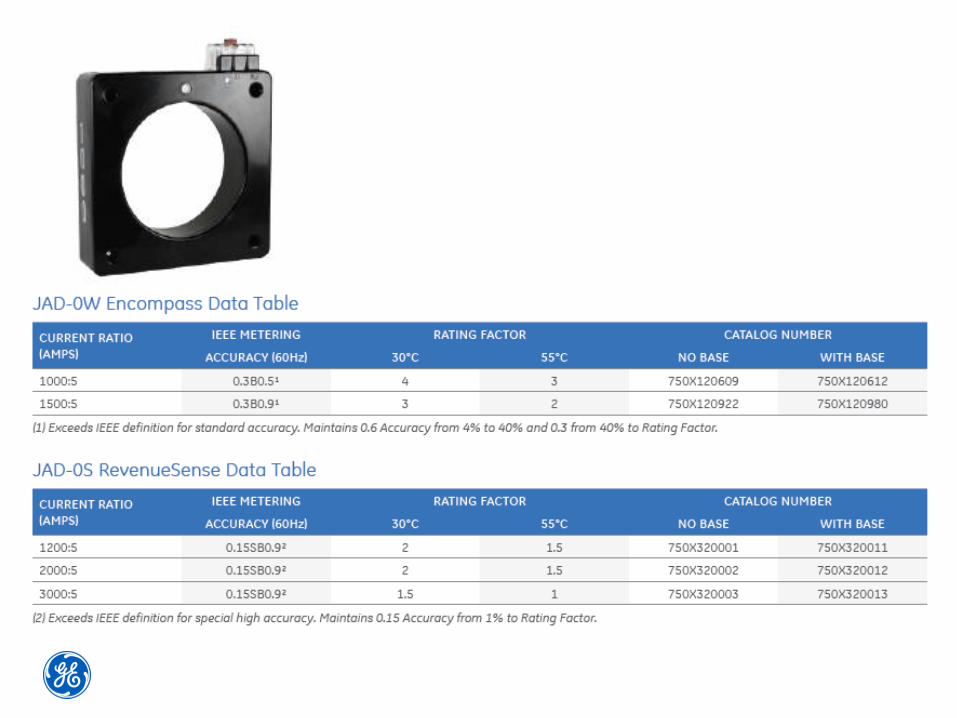
LV Extended Range

Encompass™

Low Voltage Encompass™ Series
System Current 20A 40A 60A 80A 100A 200A 400A 600A 800A 1000A 1200A 1400A 1600A 1800A 2000A
200:5 JAK-0C(Rating Factor 4.0)
±0.6% Accuracy ±0.3% Accuracy
400:5 JAK-0C(Rating Factor 4.0)
±0.6% Accuracy _ ±0.3% Accuracy
1000:5 JAK-0C(Rating Factor 2.0)
±0.6% Accuracy ±0.3% Accuracy
500:5 JAK-0W
Encompass™
(4% to 400%)
±0.6% Accuracy ±0.3% Accuracy
One Encompass CT offers equal to, or better accuracy class over the range of multiple legacy CT’s

RevenueSense™

Low Voltage RevenueSense™ Series
One RevenueSense™ CT improves accuracy over the range of multiple legacy CT’s, with significant improvement at low currents
System Current 6A 20A 40A 60A 80A 100A 200A 400A 600A 800A 1000A 1200A 1400A 1600A 1800A 2000A
200:5 JAK-0C(Rating Factor 4.0)
±0.6% Accuracy ±0.3% Accuracy
400:5 JAK-0C(Rating Factor 4.0)
±0.6% Accuracy _ ±0.3% Accuracy
1200:5 JAK-0C(Rating Factor 1.5)
±0.6% Accuracy ±0.3% Accuracy
600:5 JAK-0S
High Revenue Sense
(1% to 300%)
±0.15% Accuracy


MV Extended Range

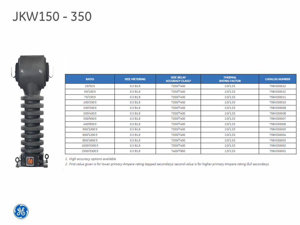
JKW150 - 350

GE ITI/
August 13, 2017Private & Confidential, not for distribution. If the reader of this presentation is not the intended person or entity, you are notified that
any unauthorized distribution, reproduction or use of this communication is strictly prohibited
Transformer Construction

GE ITI/
August 13, 2017Private & Confidential, not for distribution. If the reader of this presentation is not the intended person or entity, you are notified that
any unauthorized distribution, reproduction or use of this communication is strictly prohibited
LVInstrument
Transformer
Steel Slitter
Injection Molding
Core Winding Test Equipment
Coil Winding

GE ITI/
August 13, 2017Private & Confidential, not for distribution. If the reader of this presentation is not the intended person or entity, you are notified that
any unauthorized distribution, reproduction or use of this communication is strictly prohibited
MV Butyl RubberInstrument
Transformer

GE ITI/
August 13, 2017Private & Confidential, not for distribution. If the reader of this presentation is not the intended person or entity, you are notified that
any unauthorized distribution, reproduction or use of this communication is strictly prohibited

GE ITI/
August 13, 2017Private & Confidential, not for distribution. If the reader of this presentation is not the intended person or entity, you are notified that
any unauthorized distribution, reproduction or use of this communication is strictly prohibited
Wound Type Window Type
GE ITI/
August 13, 2017Private & Confidential, not for distribution. If the reader of this presentation is not the intended person or entity, you are notified that
any unauthorized distribution, reproduction or use of this communication is strictly prohibited
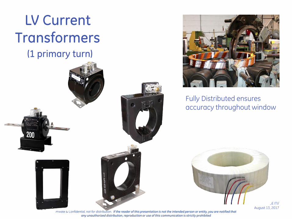
LV CurrentTransformers
(1 primary turn)
Fully Distributed ensures accuracy throughout window

GE ITI/
August 13, 2017Private & Confidential, not for distribution. If the reader of this presentation is not the intended person or entity, you are notified that
any unauthorized distribution, reproduction or use of this communication is strictly prohibited
Rectangular Split Core CTs
Popular for retrofit or temporary installations
Available for direct burial
Outdoor rated product available
UL recognized
Special Designs Available
Split Core CT’s
GE ITI/
August 13, 2017Private & Confidential, not for distribution. If the reader of this presentation is not the intended person or entity, you are notified that
any unauthorized distribution, reproduction or use of this communication is strictly prohibited
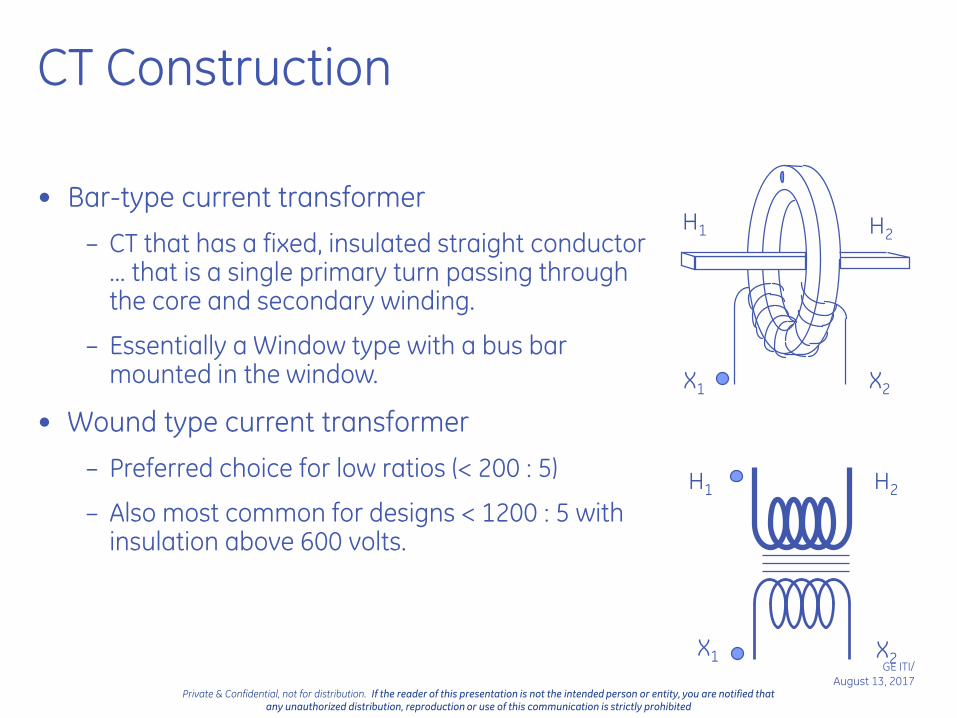
CT Construction
• Bar-type current transformer
– CT that has a fixed, insulated straight conductor ... that is a single primary turn passing through the core and secondary winding.
– Essentially a Window type with a bus bar mounted in the window.
• Wound type current transformer
– Preferred choice for low ratios (< 200 : 5)
– Also most common for designs < 1200 : 5 with insulation above 600 volts.
H1 H2
X2X1
H1 H2
X1 X2
GE ITI/
August 13, 2017Private & Confidential, not for distribution. If the reader of this presentation is not the intended person or entity, you are notified that
any unauthorized distribution, reproduction or use of this communication is strictly prohibited
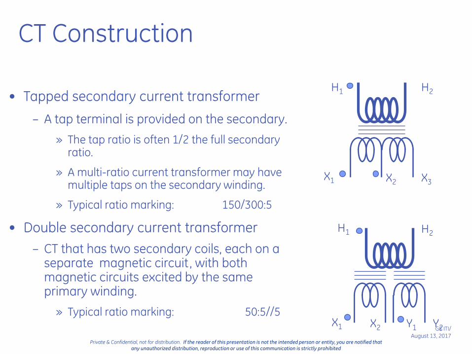
CT Construction
• Tapped secondary current transformer
– A tap terminal is provided on the secondary.
» The tap ratio is often 1/2 the full secondary ratio.
» A multi-ratio current transformer may have multiple taps on the secondary winding.
» Typical ratio marking: 150/300:5
• Double secondary current transformer
– CT that has two secondary coils, each on a separate magnetic circuit, with both magnetic circuits excited by the same primary winding.
» Typical ratio marking: 50:5//5
H1
H1
H2
H2
X1
X1
X2
X2
X3
Y1 Y2

GE ITI/
August 13, 2017Private & Confidential, not for distribution. If the reader of this presentation is not the intended person or entity, you are notified that
any unauthorized distribution, reproduction or use of this communication is strictly prohibited
VT Construction
Single Bushing
Only (1) fully insulated bushingLine to Ground connection only.
Double Bushing
Both bushings fully insulatedMay be used L-L or L-G.

GE ITI/
August 13, 2017Private & Confidential, not for distribution. If the reader of this presentation is not the intended person or entity, you are notified that
any unauthorized distribution, reproduction or use of this communication is strictly prohibited
VT Construction
Single Bushing
Double Bushing

GE ITI/
August 13, 2017Private & Confidential, not for distribution. If the reader of this presentation is not the intended person or entity, you are notified that
any unauthorized distribution, reproduction or use of this communication is strictly prohibited
VT Construction
• Voltage Transformer
– Typical ratio marking: 60:1
• Tapped secondary voltage transformer
– A tap terminal is provided on the secondary. The tap is often approximately:
– Typical ratio marking: 175/300:1
– Secondary voltage X1 to X3 = 115
or X2 to X3 = 67
Full ratio
3
H1
H1
H2
H2
X1
X1
X2
X2
X3
GE ITI/
August 13, 2017Private & Confidential, not for distribution. If the reader of this presentation is not the intended person or entity, you are notified that
any unauthorized distribution, reproduction or use of this communication is strictly prohibited
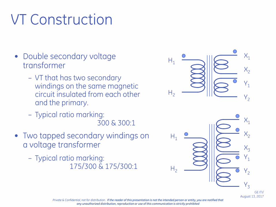
VT Construction
• Double secondary voltage transformer
– VT that has two secondary windings on the same magnetic circuit insulated from each other and the primary.
– Typical ratio marking: 300 & 300:1
• Two tapped secondary windings on a voltage transformer
– Typical ratio marking: 175/300 & 175/300:1
H1
H2
H1
H2
X1
X2
Y1
Y2
X1
X2
X3
Y1
Y2
Y3

Installations/Wiring Diagrams

Form 3S OH Primary Meter Installation

Form 5S OH Primary Meter Installation

Form 9S OH Primary Meter Installation

Form 9S Secondary Meter Installation

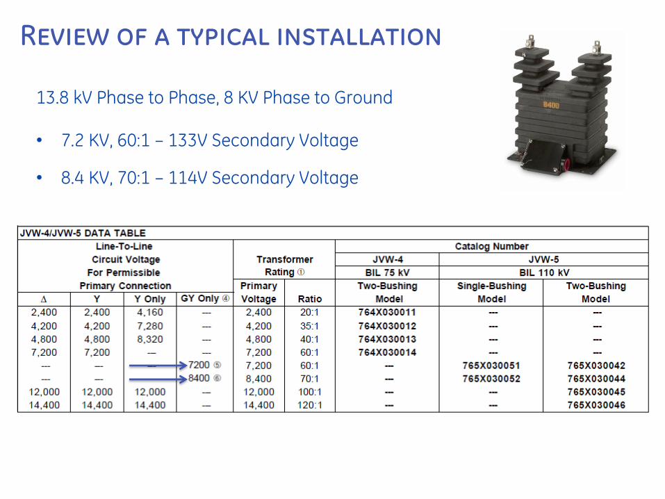
Review of a typical installation
• 13.8 kV, Grounded Wye• Max Load: 60 amps• Normal Load: 20 amps
Review of a typical installation
13.8 kV Phase to Phase, 8 KV Phase to Ground
• 7.2 KV, 60:1 – 133V Secondary Voltage
• 8.4 KV, 70:1 – 114V Secondary Voltage

Review of a typical installation
1 2 3 4 5 10A 15A 20A 25A 30A 35A 40A 45A 50A 55A 60A
0.3B1.8, RF 1.5, 40:5 ±0.6 Accuracy ±0.3 Accuracy

Review of a typical installation
1 2 3 4 5 10A 15A 20A 25A 30A 35A 40A 45A 50A 55A 60A
0.3B1.8, RF 1.5, 40:5
0.3B0.5, RF 3.0, 20:5 ±0.6 Accuracy
±0.6 Accuracy ±0.3 Accuracy
±0.3 Accuracy
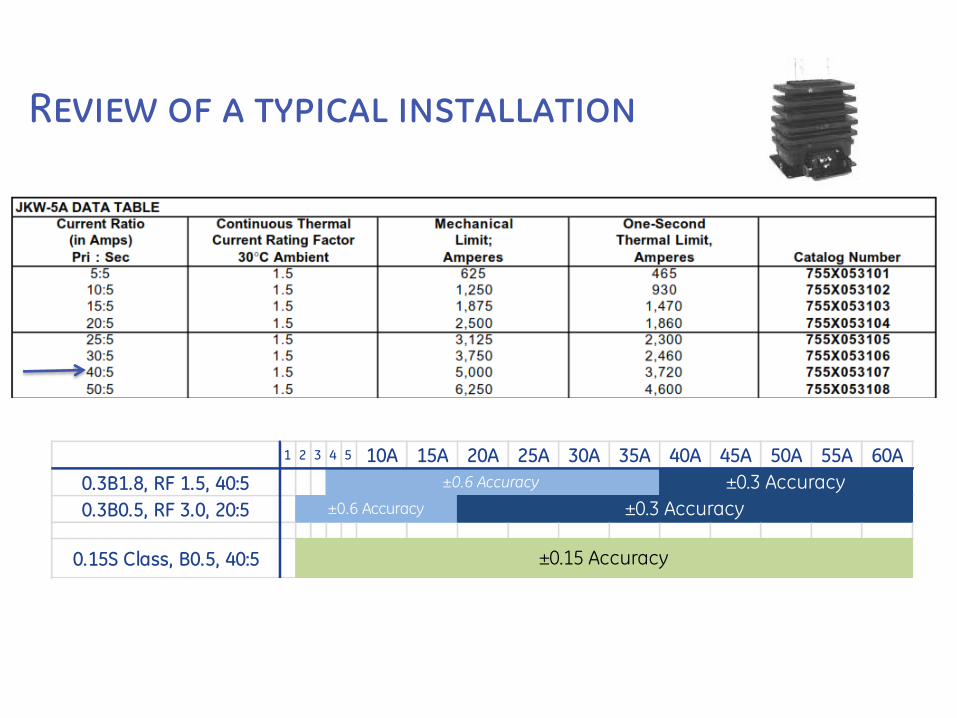
Review of a typical installation
1 2 3 4 5 10A 15A 20A 25A 30A 35A 40A 45A 50A 55A 60A
0.3B1.8, RF 1.5, 40:5
0.3B0.5, RF 3.0, 20:5
0.15S Class, B0.5, 40:5
±0.6 Accuracy
±0.6 Accuracy ±0.3 Accuracy
±0.3 Accuracy
±0.15 Accuracy

Review of a typical installation
1 2 3 4 5 10A 15A 20A 25A 30A 35A 40A 45A 50A 55A 60A 200A
1 0.3B1.8, RF 1.5, 40:5
2 0.3B0.5, RF 3.0, 20:5
3 0.15S Class, B0.5, 40:5
4 Extended Range 200:5
±0.6 Accuracy
±0.6 Accuracy ±0.3 Accuracy
±0.3 Accuracy
±0.15 Accuracy
±0.15 Accuracy

Review of a typical installation
Which is least expensive?Which is most expensive?Which offers the “fastest’ payback?
1 2 3 4 5 10A 15A 20A 25A 30A 35A 40A 45A 50A 55A 60A
1 0.3B1.8, RF 1.5, 40:5
2 10% less 0.3B0.5, RF 3.0, 20:5
3 10-20% more 0.15S Class, B0.5, 40:5
4 considerably more Extended Range 200:5 ±0.15 Accuracy
±0.6 Accuracy ±0.3 Accuracy
±0.6 Accuracy ±0.3 Accuracy
±0.15 Accuracy

Review of a typical installation
• 13.8 kV, Grounded Wyeo 70:1 PT
• Max: 60amps
Normal: 20ampsMin: 2ampso 20:5 CT, RF3.0 – Cost less, 0.3 o 40:5 CT, RF1.5 – Cost more, 0.15

What Would You Select?Current Range – 30amps – 1200amps

Encompass™ MODEL JAK-0W
What Would You Select?Current Range – 30amps – 1200amps

RevenueSense™ MODEL JAK-0S
What Would You Select?Current Range – 30amps – 1200amps

ANSI C12.20 Standard for Electricity Meters Class 0.2
1% 3% 5%
9S - CL20, 120V
For reference only
(250mA)
Meter
±0.2%
(150mA)
Meter
±0.4%
(50mA)
Meter
*NR*
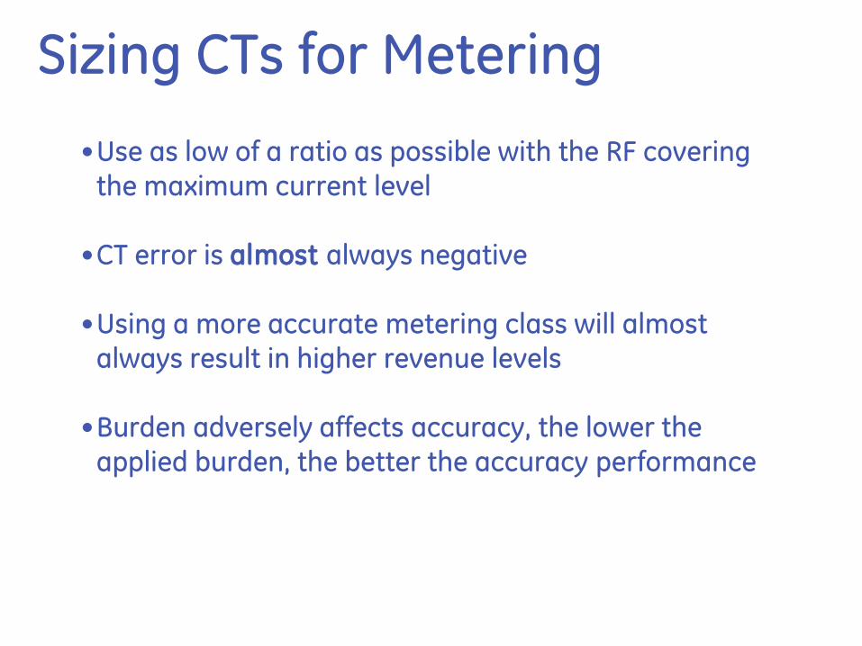
Sizing CTs for Metering
•Use as low of a ratio as possible with the RF covering the maximum current level
•CT error is almost always negative
•Using a more accurate metering class will almost always result in higher revenue levels
•Burden adversely affects accuracy, the lower the applied burden, the better the accuracy performance
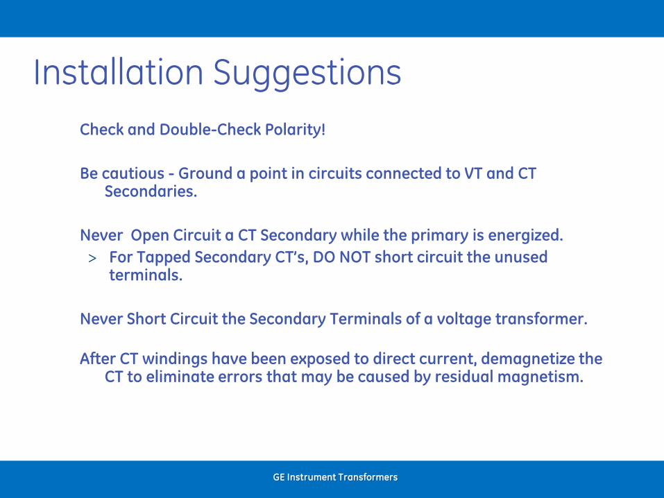
Installation Suggestions
Check and Double-Check Polarity!
Be cautious - Ground a point in circuits connected to VT and CT Secondaries.
Never Open Circuit a CT Secondary while the primary is energized.
> For Tapped Secondary CT’s, DO NOT short circuit the unused terminals.
Never Short Circuit the Secondary Terminals of a voltage transformer.
After CT windings have been exposed to direct current, demagnetize the CT to eliminate errors that may be caused by residual magnetism.
GE Instrument Transformers
GE ITI/
August 13, 2017Private & Confidential, not for distribution. If the reader of this presentation is not the intended person or entity, you are notified that
any unauthorized distribution, reproduction or use of this communication is strictly prohibited
Random Thoughts and Questions?
• Is there an advantage to using AWG10 over AWG12 for secondary wiring? Why?
• What are the Pros and Cons of using a bar type CT?
• When using SS meters, are higher or lower CT burdens required?
• Do you size CTs to Transformer KVA, Main Breaker or Customer load?
• When selecting High Accuracy CTs, how might this impact the meter?
• Why is grounding at one location important and where is this location?
• Can a LV CT be used in a MV application? Explain?
• What does a phase angle (Site Genie) tell you about a metering circuit?
GE ITI/
August 13, 2017Private & Confidential, not for distribution. If the reader of this presentation is not the intended person or entity, you are notified that
any unauthorized distribution, reproduction or use of this communication is strictly prohibited
Thank You For Your Time
Frank LopezField Application [email protected] 482-5268 http://www.gedigitalenergy.com/iti/


