44
INSTRUMENTACIÓN PARA CORTE FEMORAL REDUCIDO INSTRUMENTATION FOR REDUCED FEMORAL CUTTING

INSTRUMENTACIÓN PARA CORTE FEMORAL REDUCIDOINSTRUMENTATION FOR REDUCED FEMORAL CUTTING


ABORDAJE QUIRÚRGICO / SURGICAL APPROACH 2
TÉCNICA QUIRÚRGICA / SURGICAL TECHNIQUE 2
1. TIEMPO TIBIAL (I) / TIBIAL TIME (I) 3
1.1 Nivel de resección / Resection level 4
1.2 Corte tibial / Tibial cutting 6
2. TIEMPO FEMORAL / FEMORAL TIME 8
2.1 Perforación inicial / Initial perforation 8
2.2 Introducción varilla endomedular / Introduction of intramedullary rod 8
2.3 Medición del tamaño femoral / Measurement of femoral size 9
2.4 Colocación de máscara de corte anterior y posterior / Placing of front and back cutting mask 10
2.5 Cortes anterior y posterior / Front and back cuts 14
2.6 Colocación de máscara de corte distal / Placing of the distal cutting mask 14
2.7 Corte distal / Distal cutting 15
2.8 Espaciadores en flexión y en extensión / Spacers in flexion and in extension 16
2.9 Corte de biseles / Bevels cutting 16
2.10 Implantación del componente femoral de prueba / Implantation of femoral testing component 17
3. TIEMPO TIBIAL (II) / TIBIAL TIME (II) 19
3.1 Preparación de la quilla tibial / Preparation of tibial keel 19
3.2 Comprobación con los componentes de prueba / Verification with testing components 20
4. TIEMPO PATELAR / PATELLA TIME 22
4.1 Medición del espesor / Measurement of thickness 22
4.2 Corte y perforación rotuliano / Patellar perforation and cutting 22
5. IMPLANTACIÓN DEFINITIVA / FINAL IMPLANTATION 24
ANEXOS / ANNEXES 25
IMPLANTES E INSTRUMENTAL / IMPLANTS AND INSTRUMENTS 33
NOTAS / NOTES 40
Índice / Index

2
ABORDAJE QUIRÚRGICO / SURGICAL APPROACH Se emplea una incisión central anterior con artrotomía pararotuliana interna y luxación externa de la rótula que, en sentido proximal, se extiende hasta el tercio medio del tendón del cuádriceps y, distalmente, hasta la tuberosidad tibial.
A front central incision is used, with internal parapatellar arthrotomy, and external dislocation of the patella which, in the proximal direction, extends up to the middle third of the quadriceps tendon, and distally, to the tibial tuberosity.
SECUENCIA QUIRÚRGICA / SURGICAL SEQUENCE Tras el abordaje se aconseja el siguiente orden:
1. Corte tibial2. Corte anterior y posterior del fémur3. Corte distal4. Medición de los espacios en flexión de 90º y en extensión5. Completar los cortes femorales (biseles)6. Elección PS/NPS7. Corte del cajetín intercondilar (en caso de PS)8. Colocación de la prótesis de prueba femoral9. Preparación de la quilla tibial10. Actuación sobre la rótula11. Comprobación de la movilidad y estabilidad con los implantes de prueba12. Colocación de la prótesis definitiva
Cierre por planos dejando redones aspirativos, de manera opcional, según criterio del cirujano.
After the approach, the following order is advised:1. Tibial cutting2. Front and back cutting of the femur3. Distal cutting4. Measurement of 90º flexion and extension spaces5. Complete femoral cutting (bevels)6. PS/NPS selection7. Intercondylar box cutting (in case of PS)8. Placement of femoral testing prosthesis9. Preparation of tibial keel10. Action on patella11. Verification of mobility and stability with testing implants12. Placement of final prosthesis
Closure in layers, optionally leaving drainage points, at the discretion of the surgeon.

3
1. TIEMPO TIBIAL (I) / TIBIAL TIME (I) El diseño permite realizar la osteotomía con la guía extramedular, endomedular o la asociación de ambas.La plantilla de corte tibial (izquierda o derecha) se instala sobre la varilla extramedular que, a su vez, distalmente aloja una pinza ajustable al tobillo.
Si se va a utilizar la guía extramedular, en la zona proximal se ensambla una varilla corta auxiliar provista de dos espículas que se fijan en la zona de las espinas tibiales una vez se tiene decidida la posición de la varilla extramedular.
Si se va a utilizar la guía endomedular, previamente se efectúa la obertura del canal endomedular tibial mediante el punzón y la broca (el punto de entrada se sitúa entre las espinas tibiales). A través de la obertura practicada introduciremos el eje endomedular ensamblando a su zona proximal la varilla extramedular.
The design allows for osteotomy with the extramedullary or intramedullary guide, or both being used together.The tibial cutting template (left or right) is attached to the extramedullary rod which, in turn, distally secures adjustable clamps to the ankle.
If the extramedullary guide is going to be used, in the proximal area, a short auxiliary rod is assembled, equipped with two spicules attached to the area of the tibial spines once the position of the extramedullary rod has been decided.
If the intramedullary guide is going to be used, the tibial intramedullary canal is opened previously with the awl and the drill bit (the entry point is located between the tibial spines). Through the opening we have made, we will insert the intramedullary shaft, assembling the extramedullary rod in the proximal area.
Set tibial. Bandejas superior e inferiorTibial set. Upper and lowe trays
Nota / Note:En los casos en los que la tibia sea vara, se aconseja efectuar el punto de entrada un poco más externo y si es valga, un poco más medial.La guía endomedular se ubica en la bandeja superior del set femoral 1 de corte reducido.In cases where the tibia is pointing inward, it is advised to make the entry point a little more external, and if it is pointing outward, a little more medial. The intramedullary guide is placed on the upper tray of reduced cut femoral set 1.
Espícula anteriorAnterior spike
Espícula posteriorPosterior spike
Guía extramedularExtramedullary guide
Varilla extramedularExtramedullary rod
Plantilla de corte tibialTibial cutting template
Guía endomedularIntramedullary guide
GUÍA EXTRAMEDULAR / EXTRAMEDULARY GUIDE GUÍA ENDOMEDULAR / INTRAMEDULARY GUIDE
PalpadorProbe
Varilla extramedularExtramedullary rod

4
1.1 Nivel de resección / Resection level
Se instala el palpador en el alojamiento de la guía de corte y, con el extremo corto del palpador “10”, buscaremos el apoyo en el plato menos afectado, fijando provisionalmente la guía de corte a este nivel. Tras esto, con el extremo largo “0” del palpador localizaremos la zona tibial más deprimida del plato más afectado, pudiendo entonces presentarse estas dos situaciones:
• Que el extremo “0” no contacte, con lo que deberemos descender la guía de corte tibial hasta propiciar el contacto. A esta altura de guía de corte aseguramos realizar una resección de 1 mm por debajo de la zona más usurada.
• Que el extremo “0” no quepa. En esta situación bloquearemos la guía de corte.
The probe is installed in the cutting guide’s housing, and with the “10” short probe end, we will seek support on the least affected plateau, temporarily attaching the cutting guide at this level. After this, with the “0” long probe end, we will find the most depressed area of the tibia on the most affected plateau, the following two situations then being possible:
• That the “0” end does not make contact, which means we must lower the tibial cutting guide until making contact. At this cutting guide level, we ensure that we make a 1 mm resection below the most worn area.
• That the “0” end does not fit. In this case we will block the cutting guide.
PALPACIÓN “10” / PALPATION “10” PALPACIÓN “0” / PALPATION “0”
Palpador “0-10”“0-10” Probe
Palpación “10”“10” Palpation
Palpación “0”“0” Palpation
5
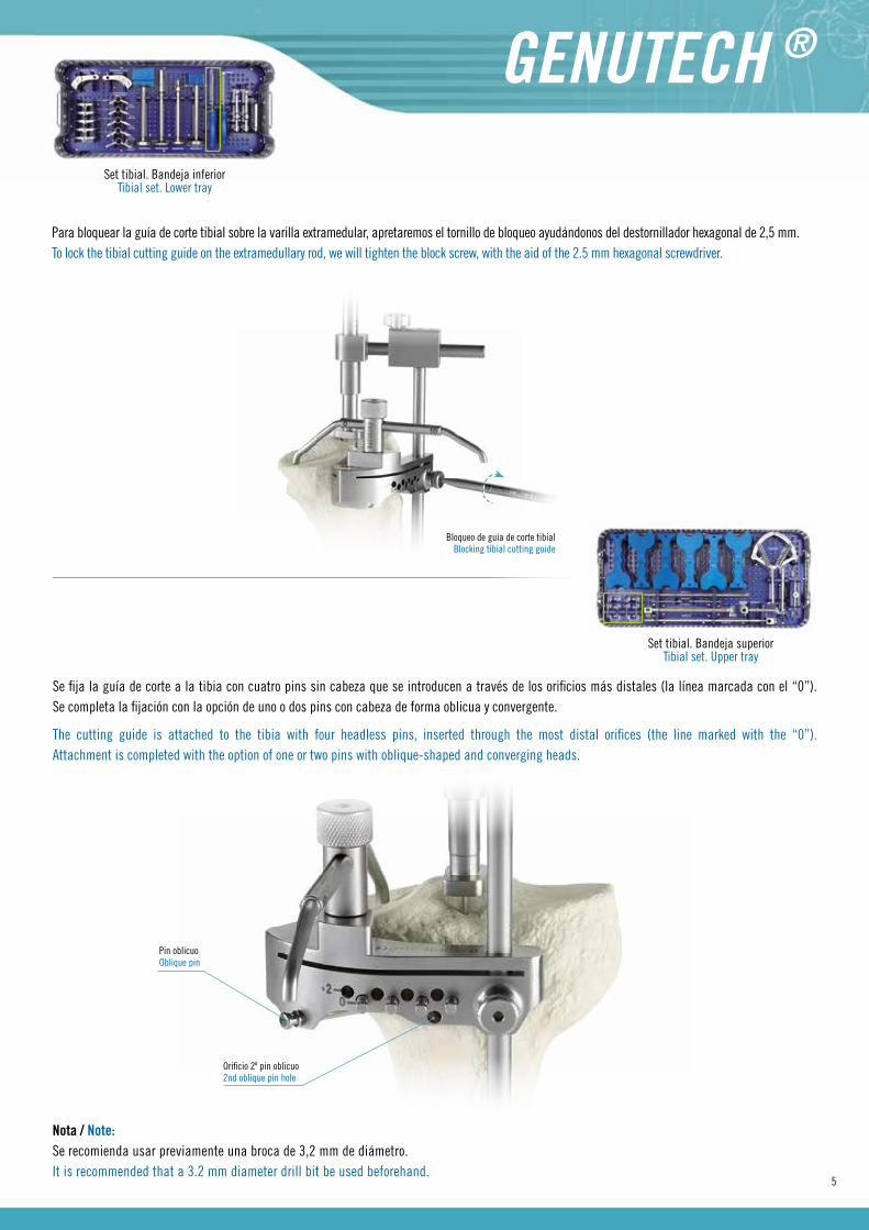
Se fija la guía de corte a la tibia con cuatro pins sin cabeza que se introducen a través de los orificios más distales (la línea marcada con el “0”). Se completa la fijación con la opción de uno o dos pins con cabeza de forma oblicua y convergente.
The cutting guide is attached to the tibia with four headless pins, inserted through the most distal orifices (the line marked with the “0”). Attachment is completed with the option of one or two pins with oblique-shaped and converging heads.
Set tibial. Bandeja inferiorTibial set. Lower tray
Para bloquear la guía de corte tibial sobre la varilla extramedular, apretaremos el tornillo de bloqueo ayudándonos del destornillador hexagonal de 2,5 mm.To lock the tibial cutting guide on the extramedullary rod, we will tighten the block screw, with the aid of the 2.5 mm hexagonal screwdriver.
Set tibial. Bandeja superiorTibial set. Upper tray
Nota / Note:Se recomienda usar previamente una broca de 3,2 mm de diámetro.It is recommended that a 3.2 mm diameter drill bit be used beforehand.
Bloqueo de guía de corte tibialBlocking tibial cutting guide
Orificio 2º pin oblicuo2nd oblique pin hole
Pin oblicuoOblique pin

6
1.2 Corte tibial / Tibial cutting
Con la guía de corte sólidamente fijada a la tibia, se retira el sistema de guías endomedulares y/o extramedulares utilizado y se realiza la osteotomía de la zona epifisaria de la tibia.
With the cutting guide firmly attached to the tibia, the intramedullary and/or extramedullary guide system is removed, and osteotomy of the tibia’s epiphyseal area is performed.
Nota / Note:Se aconseja utilizar hojas de sierra de 1.3 mm de grosor. Una sierra de menor grosor puede combarse y producir cortes inadecuados.It is advised to use 1.3 mm thick saw blades. A saw which is less thick may warp and make inadequate cuts.
Una vez efectuado el corte, para extraer la guía, se extrae el pin oblicuo con cabeza. Retirado el fragmento tibial, se recorta con una gúbia los osteofitos periféricos, si los hubiera, y se efectúa la medida de la bandeja tibial con las plantillas.
Tras este punto se inicia la instrumentación femoral.
Once the cut is made, to extract the guide, the oblique, headed pin is extracted. Once the tibia fragment is removed, any peripheral osteophytes are cut with a gouge, and the tibial tray is measured with the templates.
After this point, femoral instrumentation is begun.

7
Set tibial. Bandeja inferiorTibial set. Lower tray
Set femoral 1 corte reducido. Bandeja inferiorReduced cutting femoral set. Lower tray
Nota / Note:Se recomienda no retirar los cuatro pins sin cabeza hasta haber realizado los cortes distal y posterior del fémur ya que pueden ser de utilidad en caso de necesitar realizar un “recut” (ver Anexo 2).It is recommended not to remove the four headless pins until the distal and posterior femoral cuts have been carried out, since they may be useful if a recut must be done (see Annex 2).
Plantilla tibialTibial template
Mango soporte plantillaTibial template handle
Varilla de alineaciónAlignment shaft

8
2. TIEMPO FEMORAL / FEMORAL TIME2.1 Perforación inicial / Initial perforation
Con el punzón, o la fresa de Ø 9 mm, se perfora en el lugar escogido el punto de entrada.With the awl, or the Ø 9 mm drill, the entry point is perforated at the chosen place.
Set femoral 1 corte reducido. Bandeja superiorReduced cutting femoral set 1. Upper tray
2.2 Introducción de la varilla endomedular / Introduction of the intramedullary rod
Con la ayuda del mango en “T” de anclaje rápido, se introduce el eje endomedular a través de la perforación realizada anteriormente, dejando sinintroducir una longitud suficiente que permita instalar el medidor femoral. Una vez introducido el eje endomedular, se retira el mango en “T”.
With the aid of the “T”-shaped quick coupling handle, the intramedullary shaft is inserted through the perforation previously made, leaving enough outside the perforation to allow for installing the femoral sizing guide. Once the intramedullary shaft is inserted, the “T” shaped handle is removed.
9
Set femoral 1 corte reducido. Bandeja superiorReduced cutting femoral set 1. Upper tray
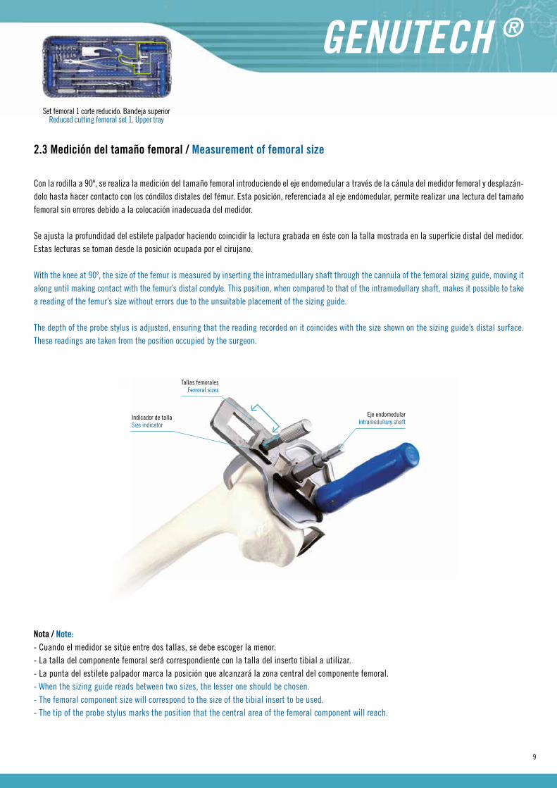
2.3 Medición del tamaño femoral / Measurement of femoral size
Con la rodilla a 90º, se realiza la medición del tamaño femoral introduciendo el eje endomedular a través de la cánula del medidor femoral y desplazán-dolo hasta hacer contacto con los cóndilos distales del fémur. Esta posición, referenciada al eje endomedular, permite realizar una lectura del tamaño femoral sin errores debido a la colocación inadecuada del medidor.
Se ajusta la profundidad del estilete palpador haciendo coincidir la lectura grabada en éste con la talla mostrada en la superficie distal del medidor. Estas lecturas se toman desde la posición ocupada por el cirujano.
With the knee at 90º, the size of the femur is measured by inserting the intramedullary shaft through the cannula of the femoral sizing guide, moving it along until making contact with the femur’s distal condyle. This position, when compared to that of the intramedullary shaft, makes it possible to take a reading of the femur’s size without errors due to the unsuitable placement of the sizing guide.
The depth of the probe stylus is adjusted, ensuring that the reading recorded on it coincides with the size shown on the sizing guide’s distal surface. These readings are taken from the position occupied by the surgeon.
Nota / Note:- Cuando el medidor se sitúe entre dos tallas, se debe escoger la menor.- La talla del componente femoral será correspondiente con la talla del inserto tibial a utilizar.- La punta del estilete palpador marca la posición que alcanzará la zona central del componente femoral.- When the sizing guide reads between two sizes, the lesser one should be chosen.- The femoral component size will correspond to the size of the tibial insert to be used.- The tip of the probe stylus marks the position that the central area of the femoral component will reach.
Tallas femoralesFemoral sizes
Eje endomedularIntramedullary shaft
Indicador de tallaSize indicator
10
Set femoral 1 corte reducido. Bandeja inferiorReduced cutting femoral set 1. Lowe tray
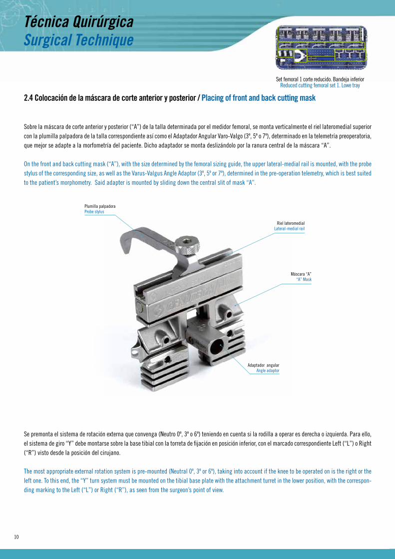
2.4 Colocación de la máscara de corte anterior y posterior / Placing of front and back cutting mask
Sobre la máscara de corte anterior y posterior (“A”) de la talla determinada por el medidor femoral, se monta verticalmente el riel lateromedial superior con la plumilla palpadora de la talla correspondiente así como el Adaptador Angular Varo-Valgo (3º, 5º o 7º), determinado en la telemetría preoperatoria, que mejor se adapte a la morfometría del paciente. Dicho adaptador se monta deslizándolo por la ranura central de la máscara “A”.
On the front and back cutting mask (“A”), with the size determined by the femoral sizing guide, the upper lateral-medial rail is mounted, with the probe stylus of the corresponding size, as well as the Varus-Valgus Angle Adaptor (3º, 5º or 7º), determined in the pre-operation telemetry, which is best suited to the patient’s morphometry. Said adapter is mounted by sliding down the central slit of mask “A”.
Se premonta el sistema de rotación externa que convenga (Neutro 0º, 3º o 6º) teniendo en cuenta si la rodilla a operar es derecha o izquierda. Para ello, el sistema de giro “Y” debe montarse sobre la base tibial con la torreta de fijación en posición inferior, con el marcado correspondiente Left (“L”) o Right (“R”) visto desde la posición del cirujano.
The most appropriate external rotation system is pre-mounted (Neutral 0º, 3º or 6º), taking into account if the knee to be operated on is the right or the left one. To this end, the “Y” turn system must be mounted on the tibial base plate with the attachment turret in the lower position, with the correspon-ding marking to the Left (“L”) or Right (“R”), as seen from the surgeon’s point of view.
Riel lateromedialLateral-medial rail
Máscara “A”“A” Mask
Adaptador angularAngle adaptor
Plumilla palpadoraProbe stylus

11
Girando el mango, se fija el sistema de rotación externo “Y” montado en su posición más alta para así facilitar posteriormente las labores de ajuste de altura de la máscara de corte “A” sobre el componente femoral.
Turning the handle, the external “Y” rotation system is attached, mounting it in its highest position so as to make it easier later on to adjust the height of the “A” cutting mask on the femoral component.
Sistema giro a externo (“Y”)External (“Y”) rotation system
Base tibialTibial base
Torreta fijación hacia abajoFixation stem through down
Girar para asegurar posición del sistema de giroTurn to ensure the position of the rotation system
Marca de altura máxima para sistema de giroMaximun height signal for rotation system
Una vez fijada la posición del sistema de giro, se introducen sus tetones sobre los orificios inferiores para pins de la máscara “A”, ejerciendo una presión final de introducción que asegurará la fijación a la máscara.
Once the rotation system’s position is set, its lugs are introduced into the lower orifices for “A” mask pins, creating final insertion pressure, which will ensure the attachment of the mask.

12
Se introduce el montaje sobre el eje endomedular previamente introducido en el fémur a través del adaptador varo-valgo.The entire assembly is coupled to the intramedullary shaft, previously inserted into the femur with the varus-valgus adaptor.
Realizado el contacto distal entre, al menos, el cóndilo más prominente con la máscara de corte “A”, se desbloquea el sistema de giro a externo girando el mango a izquierdas y se comprime el sistema asegurando, con los patines de apoyo, el contacto condilar posterior.
Once distal contact is made between, at least, the most prominent condyle and the “A” cutting mask, the external rotation system is unlocked by turning the handle to the left, and the system is compressed, ensuring subsequent condyle contact with the skids.
Adaptador angular varo-valgoVarus-valgus angle adaptor
Eje endomedularIntramedullary shaft
1º Desbloqueo1st unclock
2º Compresión2nd compression

13
Para asegurar la posición comprimida del sistema se gira el mango hacia la derecha para apretar y afianzar su posición.To ensure that the system remains compressed, the handle is turned to the right to tighten and secure its position.
Nota / Note:Retirar los pins de la tibia (dejados como referencia por si hiciera falta realizar un hipotético “recut”) si se da el caso de que al descender el sistema interfiere con estos pins.Remove the tibia pins (left as reference points in case a hypothetical recut is necessary) if, upon lowering the system, it interferes with these pins.
Así, se procede a fijar la máscara sobre el hueso con pins precedidos de un brocado previo a Ø3,2 mm.
Se aconseja colocar primero el pin distal, a través del orificio frontal que apoya sobre el cóndilo más prominente y, a continuación, se colocan los pins oblicuos situados en ambos laterales de la máscara.
Then, the mask is attached to the bone with pins after drilling a Ø3.2 mm hole.
It is recommended that the distal pin first be attached through the front orifice resting on the most prominent condyle, and then attach the oblique pins located on both sides of the mask.
Nota / Note:Alternativamente, también se puede optar por realizar una correcta colocación de la máscara de corte “A” para la realización de los cortes anterior y posterior siguiendo lo descrito en el Anexo I.
Alternatively, one may also opt to properly place the “A” cutting mask to carry out front and back cutting by following the steps in Annex I.

14
2.5 Cortes anterior y posterior / Front and back cuts
Con la máscara “A” fijada, se retira el sistema de giro a externo y el riel lateromedial tirando verticalmente de la rosca del estilete palpador. Introduci-mos un poco más el eje intramedular, si procede, para evitar interferencias con la sierra y poder realizar el corte anterior y el posterior cómodamente.
With the “A” mask attached, the rotation system is taken out, along with the lateral-medial rail, pulling vertically on the probe stylus’ threads. We insert the intramedullary shaft a little further, if necessary, to prevent it from blocking the saw, so that it is possible to perform the front and back cutting comfortably.
Set femoral 2 corte reducido. Bandeja superiorReduced cutting femoral set 2
2.6 Colocación de máscara de corte distal / Placing of the distal cutting mask
Apoyándose sobre el corte anterior previamente realizado, se instala la máscara de corte distal “B” sobre la máscara “A”, fijando su posición con pins.With the aid of the previously made cut, the “B” distal cutting mask is attached to the “A” mask, securing its position with pins.
Máscara “A”“A” Mask
Máscara “B”“B” Mask

15
Una vez instalada la máscara “B”, se retira el eje endomedular, así como la máscara “A”, extrayendo primeramente los pins distales para evitar coli-siones con la sierra de corte.
Once the “B” mask is attached, the intramedullary shaft is removed, as well as the “A” mask, firstly extracting the distal pins to avoid collisions with the cutting saw.
Precaución / Caution:En el momento de la retirada del eje endomedular, el “Adaptador Angular”(situado en la ranura central) corre el riesgo de caer, por lo que se reco-mienda sujetarlo durante esta maniobra para luego también retirarlo.When removing the intramedullary shaft, the “Angle Adaptor” located in the central slit runs the risk of falling, so it is recommended to hold it in place during this maneuver and also remove it later.
2.7 Corte distal / Distal cutting
Con la Máscara “B” instalada se realiza el corte distal.With the “B” Mask attached, the distal cut is made.
Una vez realizado el corte, se retira la máscara “B”.Once the cut is made, the “B” mask is removed.

16
2.8 Espaciadores en flexión y en extensión / Spacers in flexion and in extension
Habiendo realizado previamente el corte tibial y con los cortes distal y posterior realizados, se introducen en flexión y en extensión los espaciadores para valorar la alineación de la extremidad y la tensión ligamentaria.
Having performed the tibial cut, and with the distal and posterior cuts made, the spacers are inserted in flexion and extension to evaluate limb align-ment and ligament tension.
Nota / Note:Si se observa una tensión ligamentaria excesiva, ver Anexo 2 para la realización de “recuts”.If excessive ligament tension is observed, see Annex 2 to make “recuts”.
2.9 Corte de biseles / Bevels cutting
Sobre el Corte Anterior y asegurándonos de un correcto apoyo distal, situamos la “Mascara de Corte de Biseles” correspondiente a la talla femoral fijándola al hueso con los pins laterales.
On the Front Cut, and ensuring proper distal support, we attach the “Bevel Cutting Mask” corresponding to the size of the femur, securing it to the bone with the lateral pins.
Set femoral 2 corte reducidoReduced cutting femoral set 2
Precaución / Caution:No utilizar las posiciones de pins frontales, ya que éstas atraviesan los biseles e impedirían el paso de la sierra de corte (Ver Nota siguiente).Do not use frontal pin positions, since they go through the bevels and would impede the cutting saw’s passage (See the following Note).
Set tibial. Bandeja superiorTibial set. Upper tray

17
Una vez fijado el montaje de la máscaras se realizará en primer lugar el Corte del Bisel Posterior (recomendable para mantener la máxima superficie de apoyo distal), finalizando con el Corte del Bisel Anterior.
Once the masks are mounted, the Back Bevel Cutting is performed (recommended to maintain maximum distal support area), and finally the Front Bevel Cutting.
Nota / Note:Si se observa que la fijación de la máscara es precaria se puede mejorar de la siguiente manera:
- Introduciendo pins frontales. Se deberá tener la precaución de introducirlos siempre en la parte contraria a la que estemos realizando los cortes en bisel del cóndilo sobre el que trabajamos.- Volviendo a montar la Máscara Distal “B” y fijándola con pins para que también aporte estabilidad a la Máscara “A” durante el corte.
If you observe that the mask is not securely attached, it may be improved as follows:- Inserting frontal pins. One must take the precaution of always inserting them in the part opposite to where we are making the bevel cuts in the condyle on which we are working.- By again mounting the “B” Distal Mask, and attaching it with pins so that it also provides stability to the “A” Mask during cutting.
Set fémoro-patelar. Bandeja inferiorPatella-femoral set. Lower tray
Set PS. Bandeja superior e inferiorPS set. Upper and lower tray
2.10 Implantación del componente femoral de prueba / Implantation of femoral testing component
Se retiran las máscaras y se introduce el componente femoral de prueba “NPS” fijándose al fémur con dos pins antero-distales.• Si se escoge implantar una estabilizada posterior (PS), se acopla al componente NPS la guía de sierra para recortar el intercóndilo. Posteriormente, se coloca el componente femoral de prueba PS.
The masks are removed and the “NPS” femoral testing component is inserted, attaching it to the femur with two front-distal pins. • f one chooses to implant a posterior stabiliser (PS), the NPS component is coupled with the saw guide to recut the intercondyle area. Later on, the PS femoral test component is attached.

18
• Si se va a colocar un implante que conserva el ligamento cruzado posterior (NPS), se efectúan dos perforaciones con la broca disponible en la zona del corte distal, para alojar las prominencias del implante definitivo (tetones).
• If you are going to use an implant which preserves the posterior cruciate ligament, two perforations are made with the drill bit available in the distal cutting area, to house the protrusions of the final implant (lugs).
Módulo guía de sierraSaw guide module
Corte por sierra o cincelSaw or chisel cut
Pins anterodistalesFront-distal pins
Componente femoral prueba “NPS”“NPS” femoral testing components

19
3. TIEMPO TIBIAL (II) / TIBIAL TIME (II)
Set tibial. Bandeja inferiorTibial set. Lower tray
Sets PS y NPSPS and NPS sets
3.1 Preparación de la quilla tibial / Preparation of tibial keel
Con el componente de prueba femoral instalado (ya sea PS o NPS), se presenta la bandeja tibial con el inserto de prueba del grosor y talla determinados, apoyado sobre la superficie de corte de la tibia.
Con el mango que sujeta la bandeja se ajusta la rotación del componente tibial, comprobando el adecuado comportamiento a flexo-extensión en rela-ción al componente femoral de prueba, previamente instalado. De forma aproximada, la bandeja deberá quedar orientada hacia la TTA.
With the femoral test component installed (either PS or NPS), the tibial tray is inserted, with the test insert of a pre-determined size and thickness, supported on the tibia’s cutting surface.
With the handle which attaches the tray, the rotation of the tibia component is adjusted, verifying proper flexo-extension behaviour in relation to the femoral test component previously installed. The tray must be pointing approximately toward the ATT.
Cuando está clara la posición de rotación adecuada, se marca una señal entre la bandeja y el hueso que servirá de referencia para, posteriormente y una vez retirado el polietileno de prueba, fijar la bandeja con dos pins con cabeza.
Se introduce el escoplo-quilla de la talla escogida sobre la bandeja tibial hasta el tope. Se retira el mango de la quilla y se coloca el inserto de prueba para efectuar la comprobación definitiva con los componentes tibial y femoral de prueba correspondientes.
When it is clear that it is in a suitable rotation position, a mark is made between the tray and the bone which will act as a reference point, so that later on, once the test polyethylene is removed, the tray can be attached with two headed pins.
The keel-chisel of the chosen size is inserted as far as possible into the tibial tray. The keel handle is removed, and the test insert is attached to perform a final verification of the corresponding tibial and femoral test components.
20
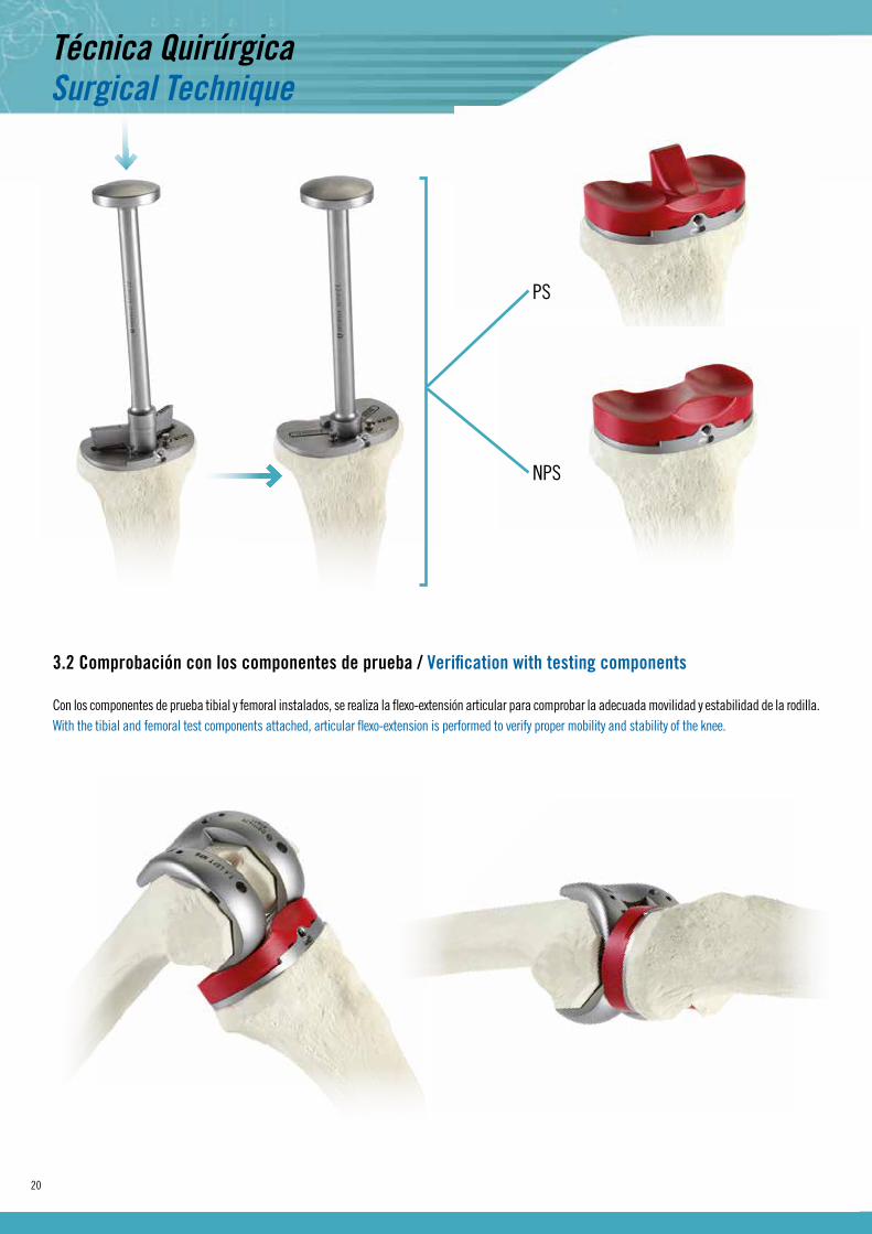
3.2 Comprobación con los componentes de prueba / Verification with testing components
Con los componentes de prueba tibial y femoral instalados, se realiza la flexo-extensión articular para comprobar la adecuada movilidad y estabilidad de la rodilla.With the tibial and femoral test components attached, articular flexo-extension is performed to verify proper mobility and stability of the knee.
PS
NPS

21
Tras efectuar dicha comprobación, se retira el inserto de prueba y la quilla, profundizando el cilindro central a la medida adecuada para alojar el tapón de la bandeja tibial, según vaya a ser éste “estándar” o “largo”.
After performing said verification, the test insert and keel are removed, deepening the central cylinder as is appropriate to house the tibial tray cover, according to whether it will be “standard” or “long”.
Nota / Note:- En caso de observar una tensión ligamentaria no adecuada que obligue a un cambio de espesor de inserto tibial, proceder a su retirada según se indica en el Anexo 3.- Si en alguna zona de la superficie tibial hay esclerosis (zona medial en el genu varo o zona lateral en el genu valgo), se recomienda efectuar en esa zona un corte con la sierra antes de introducir el escoplo-quilla, para evitar fracturas por atacar un hueso escleroso con escoplo.
- If unsuitable ligament tension is observed which forces us to change the thickness of the tibia insert, remove it as indicated in Annex 3. - If there is sclerosis in any part of the tibia surface (medial area in the genu varum or in the side area of the genu valgum), it is recommended to cut this area with the saw before introducing the chisel-keel, to avoid fractures caused by using a chisel on a bone with sclerosis.
Tapón estándarStandard cup
Tapón largoLong cup
TAPÓN ESTÁNDAR / STANDARD CUP TAPÓN LARGO / LONG CUP
Set tibial. Bandeja inferiorTibial set. Lower tray

22
With a prosthetic replacement for the patella, there are two aspects to take into account:• Knowing the original height of the patella, it is recommended leave a minimum bone thickness to avoid fracture risk (12-14 mm). • Avoid excess pressure which would result in a prosthetic patella being higher than the original. To this end, when the size of the prosthetic patella is selected, one must not only be guided by the diameter which best fits the bone resection surface, but also by the height of each patella component measurement:
Diámetro / Diameter 32 mm 34 mm 36 mm 38 mm 40 mm
Altura / Height 7 mm 8 mm 9 mm 10 mm 11 mm
4.2 Corte y perforación rotuliano / Patellar perforation and cutting
Después, se retiran los osteofitos y el tejido sinovial que rodea el borde patelar hasta ver el tendón cuadricipital y rotuliano.
Con la pinza rotuliana de resección cerrada sobre la rótula de forma que, su cortical anterior apoye sobre los pernos y la torreta esté ajustada a 12-14 mm, se efectúa el corte rotuliano.
The osteophytes and the synovial tissue surrounding the patella border are then removed, until the quadriceps and patella tendon are visible.
With the patella resection clamps, closed over the patella so that its frontal cortex rests on the bolts, and the turret is adjusted at 12 – 14 mm, the patella cut is made.
Set fémoro-patelar. Bandeja superiorPatellar-femoral set. Upper tray4. TIEMPO PATELAR / PATELAR TIME
4.1 Medición del espesor / Measurement of thickness
En la sustitución protésica de la rótula hay dos aspectos a tener en cuenta:• Conociendo la altura original de la patela, se recomienda dejar un espesor mínimo de hueso para evitar el riesgo de fractura (12-14 mm).• Evitar la híper-presión que causaría una rótula protésica de mayor altura que la original. Por ello, cuando se escoja el tamaño de la prótesis rotuliana, no sólo hay que guiarse por el diámetro que mejor satisface la superficie ósea de resección sino, también, por la altura que cada medida de componente rotuliano tiene:

23
Se posiciona el brazo móvil de la pinza de tal forma que la perforación del pivote protésico esté ligeramente medializada respecto al centro de la rótula. Se realiza la perforación con la broca específica.
The clamp’s mobile arm is positioned so that the perforation of the prosthetic pivot is slightly medialised in relation to the centre of the patella. The perforation is performed with the specific drill bit.
Colocada la rótula de prueba, se valora su recorrido sobre el canal intercondilar femoral con los movimientos de flexo-extensión.Once the test patella is in place, its movement is evaluated through the femoral intercondylar channel with flexo-extension movements.
Nota / Note:Si con la rótula de prueba (o protésica) aumenta la tensión del aparato extensor y con ello las posibilidades de subluxación y de desgaste, se optaría por un componente rotuliano menor para disminuir su altura.If, with the test (or prosthetic) patella, tension in the extensor apparatus increases, and with it, possibilities of subluxation and wear, a smaller patella component would be chosen to decrease its height.

24
5. IMPLANTACIÓN DEFINITIVA / FINAL IMPLANTATIONImplantación protésica / Prosthetic implant
Tras haber realizado las comprobaciones oportunas con los componentes de prueba femoral, tibial y patelar, serán retirados y sustituidos por las prótesis definitivas.
Una vez instalada la solución protésica, se volverá a comprobar que mantenemos el correcto funcionamiento observado anteriormente con los compo-nentes de prueba, tras lo cual procederemos a fijar definitivamente el inserto tibial roscando el perno anterior sobre la bandeja tibial.
After having performed appropriate verifications with femoral, tibial and patellar test components, they will be removed and replaced with the final prostheses.
Once the prosthetic solution is installed, we will again verify that the proper function previously observed with the test components has been maintai-ned, after which we will finally attach the tibial insert, screwing the front bolt to the tibial tray.

25
ANEXO I / ANNEX I
Otra opción para colocar la máscara de corte “A” es realizando un giro a externo de 3º introduciendo sistema alternativo de giro a externo sobre el adaptador angular.Another option for attaching the “A” cutting mask is by performing a 3º external rotation, introducing an alternative external rotation system on the angle adaptor.
SISTEMA DE COLOCACIÓN ALTERNATIVA DE MÁSCARA DE CORTE “A” CON GIRO A EXTERNO DE 3ºALTERNATIVE PLACEMENT SySTEM FOR “A” CUTTING MASk wITH 3º EXTERNAL ROTATION
Con el estilete palpador apoyando sobre la parte anterior del fémur, con la rodilla a 90º de flexión y con el montaje introducido sobre el eje intramedular, únicamente se deberá alinear el eje de alineación con el eje de carga tibial para obtener el giro a externo de la máscara.
With the probe stylus supported on the front part of the femur, with the knee at 90º flexion, and with the entire assembly only introduced on the intra-medullary shaft, the alignment shaft must be aligned with the tibia load axis to obtain the mask’s external rotation.
Manteniendo dicha posición, se aconseja colocar primero un pin distal a través del orificio frontal que apoya sobre el cóndilo más prominente y, a continuación, colocar los pins oblicuos situados en ambos laterales de la máscara. Una vez fijada la máscara, procederemos a realizar los cortes anterior y posterior.
Maintaining this position, it is recommended to first place the distal pin through the front orifice resting on the most prominent condyle, and then secure the oblique pins located on both sides of the mask. Once the mask is attached, we will make the front and back cuts.
Eje tibialTibial shaft
Varilla de alineaciónAlignment rod
3º
Eje de carga tibialTibial charge shaft Varilla de alineación
Alignment rod
ANEXOS / ANNEXES
26
ANEXO II / ANNEX II
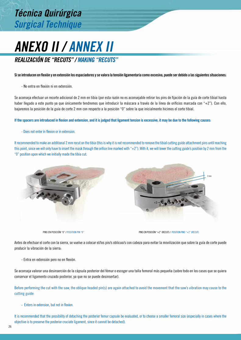
Si se introducen en flexión y en extensión los espaciadores y se valora la tensión ligamentaria como excesiva, puede ser debido a las siguientes situaciones:
- No entra en flexión ni en extensión.
Se aconseja efectuar un recorte adicional de 2 mm en tibia (por esta razón no es aconsejable retirar los pins de fijación de la guía de corte tibial hasta haber llegado a este punto ya que únicamente tendremos que introducir la máscara a través de la línea de orificios marcada con “+2”). Con ello, bajaremos la posición de la guía de corte 2 mm con respecto a la posición “0” sobre la que inicialmente hicimos el corte tibial.
If the spacers are introduced in flexion and extension, and it is judged that ligament tension is excessive, it may be due to the following causes:
- Does not enter in flexion or in extension.
It recommended to make an additional 2 mm recut on the tibia (this is why it is not recommended to remove the tibial cutting guide attachment pins until reaching this point, since we will only have to insert the mask through the orifice line marked with “+2”). With it, we will lower the cutting guide’s position by 2 mm from the “0” position upon which we initially made the tibia cut.
REALIZACIÓN DE “RECUTS” / MAkING “RECUTS”
Antes de efectuar el corte con la sierra, se vuelve a colocar el/los pin/s oblicuo/s con cabeza para evitar la movilización que sobre la guía de corte puede producir la vibración de la sierra:
- Entra en extensión pero no en flexión.
Se aconseja valorar una desinserción de la cápsula posterior del fémur o escoger una talla femoral más pequeña (sobre todo en los casos que se quiera conservar el ligamento cruzado posterior, ya que no se puede desinsertar).
Before performing the cut with the saw, the oblique headed pin(s) are again attached to avoid the movement that the saw’s vibration may cause to the cutting guide:
- Enters in extension, but not in flexion.
It is recommended that the possibility of detaching the posterior femur capsule be evaluated, or to choose a smaller femoral size (especially in cases where the objective is to preserve the posterior cruciate ligament, since it cannot be detached).
PINS EN POSICIÓN “0” / POSITION PIN “0” PINS EN POSICIÓN “+2” (RECUT) / POSITION PINS “+2” (RECUT)
2 mm

27
- Entra en flexión pero no en extensión.
Se aconseja efectuar un recorte distal de fémur del espesor que se estime oportuno (teniendo en cuenta la modificación de la interlínea).
- Enters in flexion, but not in extension.
It is recommended that a distal femoral recut be made, of the thickness judged appropriate (taking into account the modification of the inter-line).
Nota / Note:El “Recut Distal” en fémur se realizará apoyando en los planos anterior y distal la “Mascara de Recut”
The femoral “Distal Recut” is done by supporting the “Recutting Mask” on the front and distal levels.
Una vez realizado recut distal, repasaremos la posición de los biseles. Llegado a este punto se nos pueden presentar dos situaciones:
1ª. Que hayamos realizado la comprobación con los espaciadores (pag. 16) y, por ende, no tengamos los biseles cortados.
En este caso, tras el recut distal, podríamos utilizar las máscaras de corte de biseles para realizar el corte de los chaflanes y continuar con la técnica quirúrgica.
2ª. Que tengamos realizados los cortes a bisel, para lo que volveremos a montar la Máscara de Corte “A” sobre la Máscara Distal “B” volviéndola a apoyar sobre los cortes presentes y fijándola con los pins oblicuos (situados en los laterales de la máscara).
Once the distal recut is made, we return to the bevel position. Once we have reached this point, two situations may arise:
1ª. We have verified with the spacers (page 16) and, consequently, we do not have the bevels cut.In this case, after the distal recut, we could use the bevel cutting masks to cut the edges and continue with the surgical technique.
2ª. That we have made the bevel cuttings, so we will again mount the “A” Cutting Mask on the “B” Distal Mask, again supporting it on the cuts present, and attaching it with oblique pins (located on the sides of the mask).

28
Precaución / Caution:No utilizar las posiciones de pins frontales ya que éstas atravesarían los biseles e impedirían el paso de la sierra de corte.Do not use frontal pin positions since they go through the bevels and would impede the cutting saw’s passage.
Una vez fijado el montaje se realizan los cortes de los biseles.Once the entire assembly is attached the bevel cuts are made.
Nota / Note:Si se observa que la fijación de la máscara es precaria se puede mejorar de la siguiente manera:
- Introduciendo pins frontales. Se deberá tener la precaución de introducirlos siempre en la parte contraria a la que estemos realizando los cortes en bisel.- Montando pins sobre la Máscara distal “B”. Para que también aporte estabilidad a la Máscara “A” durante el recorte de los biseles, en casos excepcionales de extrema diferencia de fijación.
If you observe that the mask is not securely attached, it may be improved as follows:- Inserting frontal pins. One must take the precaution of always inserting them in the part opposite to where we are making the bevel cuts.- Put pins on the “B” Distal Mask as well so that it provides stability to the “A” Mask while re-cutting bevels, in exceptional cases of extreme attachment deficiency.

29
ANEXO III / ANNEX III
El clipado se realiza de forma manual apoyando primero la parte posterior del inserto sobre la bandeja tibial y presionando anteriormente ambas piezas hasta realizar el clipado.
Clipping is done manually, first supporting the back part of the insert on the tibial tray and pressing both pieces on the front until clipping is achieved.
CLIPADO y EXTRACCIÓN DE INSERTOS TIBIALES / CLIPPING AND EXTRACTING TIBIA INSERTS
Para la extracción del inserto tibial se introduce la punta plana del extractor en una de las ranuras que el inserto tibial deja al cliparse sobre la bandeja tibial realizando un leve giro (no hacer palanca).
To extract the tibia insert, the flat tip of the extractor is inserted into one of the slits left by the tibia insert upon being clipped to the tibial tray, rotating slightly (do not pry out).

30
ANEXO IV / ANNEX IV
La pinza de compresión patelar, ubicada en la bandeja superior del set fémoro-patelar, está diseñada para provocar el rebose del cemento óseo y el mantenimiento de la presión durante el tiempo de fraguado necesario para la correcta fijación de la patela.
The patellar compression clamps, located on the upper tray of the patellofemoral set, is designed to make the bone cement brim up, and to maintain pressure during the hardening time necessary to properly attach the patella.
PINZA DE COMPRESIÓN PATELAR / PATELLAR COMPRESSION CLAMPS

31
ANEXO V / ANNEX V
El sistema Genutech dispone de un impactor de bandeja y de un impactor de componente tibial. Este último permite impactar el componente comple-tamente montado sin dañar las zonas funcionales del inserto tibial.
The Genutech System has a tray impactor and a tibial component impactor. This latter instrument can impact the component once fully in position without damaging the functional areas of the tibial graft.
IMPACTORES / IMPACTORS
Impactores tibiales / Tibial impactors
IMPACTOR DE BANDEjA TIBIAL / TIBIAL TRAY IMPACTOR IMPACTOR DE INSERTO TIBIAL / TIBIAL INSERT IMPACTOR

En la colocación del componente femoral podemos asistirnos de introductor/extractor de componentes femorales para guiar la introducción y colocación por impactación del componente para, posteriormente, ultimar su fijación utilizando el impactor femoral.
When positioning the femoral component, we can use the inserter/extractor for femoral components to guide the insertion and impact positioning of the component, then complete its fixation using the femoral impactor.
Impactores femorales / Femoral impactors
INTRODUCTOR / EXTRACTOR - INSERTER / EXTRACTOR
IMPACTOR FEMORAL / FEMORAL IMPACTOR
Para realizar pequeños ajustes sobre zonas puntuales disponemos de un impactor de menor tamaño. Este impactor, conjuntamente con el primero, puede utilizar-se en la extracción de los componentes femorales de prueba.
To make minor adjustments in specific areas, we have a smaller impactor. This impactor, in conjunction with the first one, can be used to extract the test femoral components.
Se dispone de un impactor de pins que, de forma eventual, también puede utilizarse como barra extractora.There is a pin impactor which could be used as an extractor rod.
Impactor de pins / Pins impactor
32

33
Componente femoral NPS sin cementoNPS cementless femoral component
Izquierdo Left Talla Size Derecho Right
Ref. D8011120E 1 Ref. D8011110E
Ref. D8011220E 2 Ref. D8011210E
Ref. D8011320E 3 Ref. D8011310E
Ref. D8011420E 4 Ref. D8011410E
Ref. D8011520E 5 Ref. D8011510E
Componente femoral PS sin cemento*PS cementless femoral component*
Izquierdo Left Talla Size Derecho Right
Ref. D8012120E 1 Ref. D8012110E
Ref. D8012220E 2 Ref. D8012210E
Ref. D8012320E 3 Ref. D8012310E
Ref. D8012420E 4 Ref. D8012410E
Ref. D8012520E 5 Ref. D8012510E
*Estos componentes se fabrican bajo solicitud. Contactar con Surgival. *These components are manufactured on order. Contact Surgival.
Componente femoral NPS con cementoNPS cemented femoral component
Izquierdo Left Talla Size Derecho Right
Ref. D8021120E 1 Ref. D8021110E
Ref. D8021220E 2 Ref. D8021210E
Ref. D8021320E 3 Ref. D8021310E
Ref. D8021420E 4 Ref. D8021410E
Ref. D8021520E 5 Ref. D8021510E
Componente femoral PS con cementoPS cemented femoral component
Izquierdo Left Talla Size Derecho Right
Ref. D8022120E 1 Ref. D8022110E
Ref. D8022220E 2 Ref. D8022210E
Ref. D8022320E 3 Ref. D8022310E
Ref. D8022420E 4 Ref. D8022410E
Ref. D8022520E 5 Ref. D8022510E
Inserto tibial NPSNPS tibial insert
Talla Size Longitud Length
Ref. D8041100E 1 10 mm
Ref. D8041120E 1 12 mm
Ref. D8041140E 1 14 mm
Ref. D8041160E 1 16 mm
Ref. D8042100E 2 10 mm
Ref. D8042120E 2 12 mm
Ref. D8042140E 2 14 mm
Ref. D8042160E 2 16 mm
Ref. D8043100E 3 10 mm
Ref. D8043120E 3 12 mm
Ref. D8043140E 3 14 mm
Ref. D8043160E 3 16 mm
Talla Size Longitud Length
Ref. D8044100E 4 10 mm
Ref. D8044120E 4 12 mm
Ref. D8044140E 4 14 mm
Ref. D8044160E 4 16 mm
Ref. D8045100E 5 10 mm
Ref. D8045120E 5 12 mm
Ref. D8045140E 5 14 mm
Ref. D8045160E 5 16 mm
Implants
34
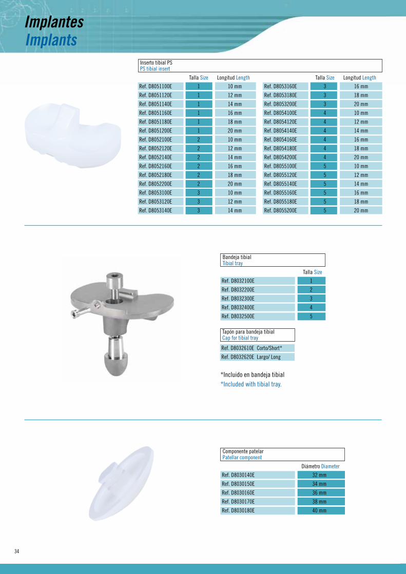
ImplantsInserto tibial PSPS tibial insert
Talla Size Longitud Length
Ref. D8051100E 1 10 mm
Ref. D8051120E 1 12 mm
Ref. D8051140E 1 14 mm
Ref. D8051160E 1 16 mm
Ref. D8051180E 1 18 mm
Ref. D8051200E 1 20 mm
Ref. D8052100E 2 10 mm
Ref. D8052120E 2 12 mm
Ref. D8052140E 2 14 mm
Ref. D8052160E 2 16 mm
Ref. D8052180E 2 18 mm
Ref. D8052200E 2 20 mm
Ref. D8053100E 3 10 mm
Ref. D8053120E 3 12 mm
Ref. D8053140E 3 14 mm
Talla Size Longitud Length
Ref. D8053160E 3 16 mm
Ref. D8053180E 3 18 mm
Ref. D8053200E 3 20 mm
Ref. D8054100E 4 10 mm
Ref. D8054120E 4 12 mm
Ref. D8054140E 4 14 mm
Ref. D8054160E 4 16 mm
Ref. D8054180E 4 18 mm
Ref. D8054200E 4 20 mm
Ref. D8055100E 5 10 mm
Ref. D8055120E 5 12 mm
Ref. D8055140E 5 14 mm
Ref. D8055160E 5 16 mm
Ref. D8055180E 5 18 mm
Ref. D8055200E 5 20 mm
Bandeja tibialTibial tray
Talla Size
Ref. D8032100E 1
Ref. D8032200E 2
Ref. D8032300E 3
Ref. D8032400E 4
Ref. D8032500E 5
Tapón para bandeja tibialCap for tibial tray
Ref. D8032610E Corto/Short*
Ref. D8032620E Largo/ Long
Componente patelarPatellar component
Diámetro Diameter
Ref. D8030140E 32 mm
Ref. D8030150E 34 mm
Ref. D8030160E 36 mm
Ref. D8030170E 38 mm
Ref. D8030180E 40 mm
*Incluido en bandeja tibial*Included with tibial tray.

35
Bandeja superior / Upper tray
D8401200 Set instrumental tibial / Tibial instrumental set
Set completo instrumental rodilla primaria reducida Genutech®
Genutech® reduced primary knee instrumental complete setRef. D8600000
Bandeja inferior / Lower tray
1 Guía de corte tibialTibial cutting guide
Ref. D8220130 izquierda/left
Ref. D8220120 derecha/right
10 Mango soporte plantilla tibialTibial template handle
Ref. D8220520
1 Espaciador de pruebaTrial spacer
Longitud Length
Ref. D8120210 10 mm
Ref. D8120220 12 mm
Ref. D8120230 14 mm
Ref. D8120240 16 mm
Ref. D8120250 18 mm
Ref. D8120260 20 mm
2 Pin ø3,4x55 mm con cabezaø3,4x55 mm pin with head
Ref. D8210160
3 Pin ø3,4x55 mm sin cabezaø3,4x55 mm headless support pin
Ref. D8210165
4 Guía tibial simpleSimple tibial guide
Ref. D8220111
5 Pin ø3,4x80 mm sin cabezaø3,4x80 mm headless support pin
Ref. D8210166
6 Soporte guía tibial (3 piezas)Tibial guide support (3 pieces)
Ref. D8220110
7 Pinza distal para guía tibialDistal forcep for tibial guide
Ref. D8220140
8 Sistema fijación extramedularExtramedullary fixation system
Ref. D8220150
9 Palpador tibialTibial probe
Ref. D8220270
1
2 3
4
5
6
7
8
9
Plantilla tibial de pruebaTrial tibial template
Talla Size
Ref. D8220410 1
Ref. D8220420 2
Ref. D8220430 3
Ref. D8220440 4
Ref. D8220450 5
2
Cincel quillaKeel chisel
Talla Size
Ref. D8220470 1
Ref. D8220480 2
Ref. D8220490 3
Ref. D8220500 4
Ref. D8220510 5
3
4 Impactor tibialTibial impactor
Ref. D8220610
5 Cincel intramedularIntramedullary chisel
Ref. D8220640
6 Impactor de quillaKeel impactor
Ref. D8220460
7 Impactor bandeja tibialTibial tray impactor
Ref. D8220615
8 Destornillador 2,5 mm2,5 mm screwdriver
Ref. D8220635
9 Extractor de insertosInserts extractor
Ref. D8220620
11 Mango soporte perno fijaciónFixation bolt handle
Ref. D82205301
2 3
4
5 6 7
8 9 10 11
InstrumentsInstrumental

36
InstrumentsInstrumental
Bandeja superior / Upper tray
D8401300 Set intrumental fémoro-patelar / Patella-femoral instrumental set
Bandeja inferior / Lower tray
Patela de pruebaTrial patella
Diámetro Diameter
Ref. D8130140 32 mm
Ref. D8130150 34 mm
Ref. D8130160 36 mm
Ref. D8130170 38 mm
Ref. D8130180 40 mm
1 2 Broca para patelaPatellar drill bit
Ref. D8230120
3 Pinza para resección patelarPatellar resection clamp
Ref. D8230110
4 Pinza abrazadera para patelaPatellar clamp
Ref. D8230130
Componentes femorales de prueba NPSNPS femoral trial components
Izquierdo Left Talla Size Derecho Right
Ref. D8111120 1 Ref. D8111110
Ref. D8111220 2 Ref. D8111210
Ref. D8111320 3 Ref. D8111310
Ref. D8111420 4 Ref. D8111410
Ref. D8111520 5 Ref. D8111510
4
1 EscoploChisel
Ref. D8210220
2 Broca para tetones NPSNPS drill bit
Ref. D8210230
3 Módulo guía para sierraSaw guide module
Ref. D8210240
5 Impactor femoralFemoral impactor
Ref. D8210210
6 Pin ø 3,4x40 mm con cabezaø 3,4x40 mm pin with head
Ref. D8210162
1
2
3 4
1
2
34
4
5
6
37
Bandeja superior / Upper tray
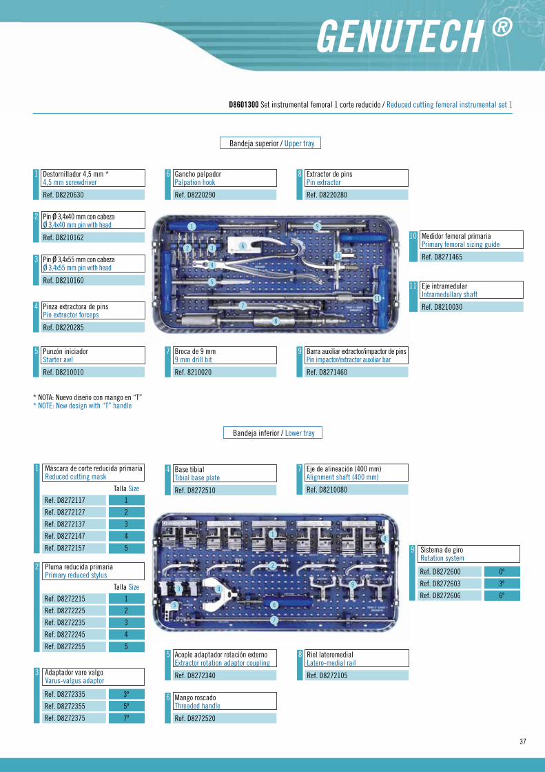
D8601300 Set instrumental femoral 1 corte reducido / Reduced cutting femoral instrumental set 1
Bandeja inferior / Lower tray
1 Destornillador 4,5 mm *4,5 mm screwdriver
Ref. D8220630
1
2 3
5
6
7
8
9
10
11
6 Gancho palpadorPalpation hook
Ref. D8220290
2 Pin ø 3,4x40 mm con cabezaø 3,4x40 mm pin with head
Ref. D8210162
43 Pin ø 3,4x55 mm con cabeza
ø 3,4x55 mm pin with head
Ref. D8210160
9 Barra auxiliar extractor/impactor de pinsPin impactor/extractor auxiliar bar
Ref. D8271460
8 Extractor de pinsPin extractor
Ref. D8220280
4 Pinza extractora de pinsPin extractor forceps
Ref. D8220285
10 Medidor femoral primariaPrimary femoral sizing guide
Ref. D8271465
5 Punzón iniciadorStarter awl
Ref. D8210010
7 Broca de 9 mm9 mm drill bit
Ref. 8210020
11 Eje intramedularIntramedullary shaft
Ref. D8210030
1
Máscara de corte reducida primariaReduced cutting mask
Talla Size
Ref. D8272117 1
Ref. D8272127 2
Ref. D8272137 3
Ref. D8272147 4
Ref. D8272157 5
1
2Pluma reducida primariaPrimary reduced stylus
Talla Size
Ref. D8272215 1
Ref. D8272225 2
Ref. D8272235 3
Ref. D8272245 4
Ref. D8272255 5
2
3
Adaptador varo valgoVarus-valgus adaptor
Ref. D8272335 3º
Ref. D8272355 5º
Ref. D8272375 7º
3
4
4 Base tibialTibial base plate
Ref. D8272510
5
5 Acople adaptador rotación externoExtractor rotation adaptor coupling
Ref. D8272340
6
7 Eje de alineación (400 mm)Alignment shaft (400 mm)
Ref. D8210080
7
6 Mango roscadoThreaded handle
Ref. D8272520
8 Riel lateromedialLatero-medial rail
Ref. D8272105
8
9
Sistema de giroRotation system
Ref. D8272600 0º
Ref. D8272603 3º
Ref. D8272606 6º
9
* NOTA: Nuevo diseño con mango en “T” * NOTE: New design with “T” handle

38
InstrumentsInstrumental
Máscara de corte biselesBevel cutting mask
Talla Size
Ref. D8272051 1
Ref. D8272052 2
Ref. D8272053 3
Ref. D8272054 4
Ref. D8272055 5
1
D8601400 Set femoral instrumental 2 corte reducido / Reduced cutting femoral instrumental set 2
Insertos tibiales de prueba NPSNPS tibial trial insertst
Talla Size
Ref. D8141100 1x10 mm
Ref. D8141120 1x12 mm
Ref. D8141140 1x14 mm
Ref. D8141160 1x16 mm
Ref. D8142100 2x10 mm
Ref. D8142120 2x12 mm
Ref. D8142140 2x14 mm
Ref. D8142160 2x16 mm
Ref. D8143100 3x10 mm
Ref. D8143120 3x12 mm
1
Talla Size
Ref. D8143140 3x14 mm
Ref. D8143160 3x16 mm
Ref. D8144100 4x10 mm
Ref. D8144120 4x12 mm
Ref. D8144140 4x14 mm
Ref. D8144160 4x16 mm
Ref. D8145100 5x10 mm
Ref. D8145120 5x12 mm
Ref. D8145140 5x14 mm
Ref. D8145160 5x16 mm
D8402100 Set instrumental NPS / NPS instrumental set
1
23
4
5
2 Introductor/extractor componentes femoralesFemoral component intramedyllary/extractor
Ref. D8271415
3 Máscara de corte distal reducida primariaReduced distal cutting mask primary
Ref. D8272050
4 Impactor de componente femoralFemoral component impactor
Ref. D8272530
5 Máscara de recut distal reducidaReduced distal recutting mask
Ref. D8272165

39
Bandeja superior / Upper tray
Bandeja inferior / Lower tray
D8403100 Set instrumental PS/ PS instrumental set
Insertos tibiales de prueba PSPS tibial trial inserts
Talla Size
Ref. D8151100 1x10 mm
Ref. D8151120 1x12 mm
Ref. D8151140 1x14 mm
Ref. D8151160 1x16 mm
Ref. D8151180 1x18 mm
Ref. D8151200 1x20 mm
Ref. D8152100 2x10 mm
Ref. D8152120 2x12 mm
Ref. D8152140 2x14 mm
Ref. D8152160 2x16 mm
Talla Size
Ref. D8152180 2x18 mm
Ref. D8152200 2x20 mm
Ref. D8153100 3x10 mm
Ref. D8153120 3x12 mm
Ref. D8153140 3x14 mm
Ref. D8153160 3x16 mm
Ref. D8153180 3x18 mm
Ref. D8153200 3x20 mm
Ref. D8154100 4x10 mm
Ref. D8154120 4x12 mm
Talla Size
Ref. D8154140 4x14 mm
Ref. D8154160 4x16 mm
Ref. D8154180 4x18 mm
Ref. D8154200 4x20 mm
Ref. D8155100 5x10 mm
Ref. D8155120 5x12 mm
Ref. D8155140 5x14 mm
Ref. D8155160 5x16 mm
Ref. D8155180 5x18 mm
Ref. D8155200 5x20 mm
1
Componentes femorales de prueba PSPS femoral trial components
Derecha Right Talla Size
Ref. D8112110 1
Ref. D8112210 2
Ref. D8112310 3
Ref. D8112410 4
Ref. D8112510 5
Izquierda Left Talla Size
Ref. D8112120 1
Ref. D8112220 2
Ref. D8112320 3
Ref. D8112420 4
Ref. D8112520 5
1

40


0318 IROGEDTQ01
/ 07
-201
5 © R
ev. 1
El m
arca
do C
E es
vál
ido
únic
amen
te s
i tam
bién
est
á im
pres
o en
la e
tique
ta d
el p
rodu
cto.


