2/7/2016 1 Instrumentation Technology INST‐1010 Introduction to Process Control Basile Panoutsopoulos, Ph.D. CCRI Department of Engineering and Technology 1 B. Panoutsopoulos Engineering Physics II Today’s meeting • Call Attendance • Announcements • Collect Homework • Give examination – Display time clock • Collect examinations • Previous examination – Return – Discussion • Introduce topic – Provide Handouts – Socratic discussion – Practice ‐ Problems B. Panoutsopoulos Engineering Physics II 2 Themes • List the classifications of industrial control systems • Describe the differences among industrial control systems • Provide examples of each type • Define common terms associated with industrial control systems Instrumentation Technology: Process Control 3 B. Panoutsopoulos
Transcript
2/7/2016
1
Instrumentation TechnologyINST‐1010
Introduction to Process Control
Basile Panoutsopoulos, Ph.D.
CCRI
Department of Engineering and Technology
1B. Panoutsopoulos Engineering Physics II
Today’s meeting
• Call Attendance• Announcements
• Collect Homework• Give examination
– Display time clock
• Collect examinations
• Previous examination– Return– Discussion
• Introduce topic– Provide Handouts– Socratic discussion– Practice ‐ Problems
B. Panoutsopoulos Engineering Physics II 2
Themes
• List the classifications of industrial control systems
• Describe the differences among industrial control systems
• Provide examples of each type
• Define common terms associated with industrial control systems
Instrumentation Technology: Process Control
3B. Panoutsopoulos
2/7/2016
2
Themes
• Describe the differences between– open‐ and
– closed‐loop systems
• Define common terms associated with– open‐ and
– closed‐loop systems
• List the factors that affect the dynamic response of a closed‐loop system
• Describe the operation of feed‐forward control
Instrumentation Technology: Process Control
4B. Panoutsopoulos
Themes
• List three factors that cause the controlled variable to differ from the set‐point
Instrumentation Technology: Process Control
5B. Panoutsopoulos
Themes
• Process Control
• Variables
• Automation
• Control Elements
• Control Loops
• Common Control Strategies
• Instrumentation
• Instrumentation and Industry
• Training
• Industry and Standards Organizations
Instrumentation Technology: Process Control
6B. Panoutsopoulos
2/7/2016
3
HISTORICAL INTRODUCTION
Instrumentation Technology: Process Control
7B. Panoutsopoulos
Historical Introduction
• Industrial revolution (England) 1700s
• US surpasses England as the manufacturing leader
• 1900s the electric motor replaces steam engine and water wheels.
Instrumentation Technology: Process Control
8B. Panoutsopoulos
Historical Introduction
• Machines are manually operated.• Between World War I and World War II the Feedback
Control System is developed.• Manually operation is replaced by automatic operation• The term Industrial control is used to describe this type
of system.• During World War II significant advantages occurs in
developing theory and practice of Automatic Control Systems.
• This technology was transferred to commercial applications.
Instrumentation Technology: Process Control
9B. Panoutsopoulos
2/7/2016
4
Historical Introduction
• Today’s technicians:
– Install
– Troubleshoot
– Maintain
– Repair
• The today’s technicians must be highly trained.
Instrumentation Technology: Process Control
10B. Panoutsopoulos
INDUSTRIAL CONTROL SYSTEMS
Instrumentation Technology: Process Control
11B. Panoutsopoulos
Process Operation
• Instrumentation– Measure and control variables in industrial processes
• Example: Process variables measured include pressure, flow, temperature, level, ph, humidity
– Based on data measured, controller reacts accordingly
• No action, increase, decrease
• Feedback
– Based on measured value, corrective signal sent to controller
• Speed of response depends on application
Instrumentation Technology: Process Control
18B. Panoutsopoulos
2/7/2016
7
Open/Closed Loop Systems
• Open Loop
– No feedback
• Closed Loop
– Uses feedback for continuous correction
Instrumentation Technology: Process Control
19B. Panoutsopoulos
Noise
• Noise
– Any signal other than the desired signal
– Many sources
– Noise gets added to signal
– Large snr (Signal to Noise Ratio) desired
Instrumentation Technology: Process Control
20B. Panoutsopoulos
Kinds of Signals
• Signal:
– Electrical
• Analog ‐ continuous range of values
• Digital – discrete values, 1/0, on/off, true/false
– Pneumatic
• Air pressure
Instrumentation Technology: Process Control
21B. Panoutsopoulos
2/7/2016
8
Kinds of Displays
• Audible– Tones, beeps, bells, etc.
• Visual– Pointer
• Edgewise, circular• Scale typically graduated
– Linear, nonlinear, logarithmic
– Digital displays• Direct reading of variable• Rapidly replacing many pointer scale displays
– Monitors• Text, graphics, color used to define process, variables, …
Instrumentation Technology: Process Control
22B. Panoutsopoulos
Remote versus Local Display
• Local
– Variable measured and displayed at source
• Remote
– Variable measured at source displayed remotely through a separate transmitter
Instrumentation Technology: Process Control
23B. Panoutsopoulos
Functions and Elements in an Automatic Control System
Instrumentation Technology: Process Control
24B. Panoutsopoulos
2/7/2016
9
Process Control
• The regulation of system behavior by monitoring measured data from one or more sensors.
Instrumentation Technology: Process Control
25B. Panoutsopoulos
The need for a Control System
• Do we need to control a system at all?• Let us consider the following situations:
– What good is an airplane if you are a pilot and you can't make it go where you want it to go?
– What good is a chemical products production line if you can't control temperature, pressure and pH in the process and you end up making tons of garbage?
– What good is an oven if you can't control the temperature?– What good is a heat‐treating department that is used to harden metal parts if you can't control the temperature?
– What good is a pump if you can't control the flow rate it produces? (And, there are many times when the flow rate must be controlled.)
Instrumentation Technology: Process Control
26B. Panoutsopoulos
The need for a Control System
• The common denominator in all of these questions is that there is some physical quantity that must be somehow controlled in a way that ensures that the physical quantity takes on a value or, more practically, in a range between two values, that is specified.
• There are even times when the physical quantity should take on some pre‐determined values that follow a function of time.– Example of that would be landing an airplane where you want
the plane to meet the ground following a specified curve.
• We need to think about how to control physical quantities in general, and to determine what can be done ‐ in a general way ‐ to implement any scheme we devise.
Instrumentation Technology: Process Control
27B. Panoutsopoulos
2/7/2016
10
Typical control system
• Control system
• Control system input(s)
• Control system output(s)
Instrumentation Technology: Process Control
28B. Panoutsopoulos
Typical Control LoopsOpen Loop Control System
Instrumentation Technology: Process Control
29B. Panoutsopoulos
Typical Control LoopsClosed Loop Control System
Instrumentation Technology: Process Control
30B. Panoutsopoulos
2/7/2016
11
Closed Loop Control SystemFeedback
Instrumentation Technology: Process Control
31B. Panoutsopoulos
Typical Automatic Control System
• Automatic control system
• Manipulated variable(s) ‐ Controlled system input(s)
• Controlled variable(s) ‐ Control system output(s)
Instrumentation Technology: Process Control
32B. Panoutsopoulos
• Automatic control system:– An automatic control system is a preset closed‐loop control system that requires no operator action.
• Manipulated variable(s) ‐ Controlled system input(s)– A manipulated variable is the process variable that is acted on by the control system to maintain the controlled variable at the specified value or within the specified range.
• Controlled variable(s) ‐ Control system output(s)– A controlled variable is the process variable that is maintained at a specified value or within a specified range.
Typical Automatic Control System
Instrumentation Technology: Process Control
33B. Panoutsopoulos
2/7/2016
12
Typical control system
• Control system
• Control system input(s)
• Control system output(s)
Instrumentation Technology: Process Control
34B. Panoutsopoulos
Typical control system
• Control system
• Control system input(s)
• Control system output(s)
Instrumentation Technology: Process Control
35B. Panoutsopoulos
Typical control system
• Control system
• Control system input(s)
• Control system output(s)
Instrumentation Technology: Process Control
36B. Panoutsopoulos
2/7/2016
13
Automatic Process ControlFunctions of an Automatic Control
System• Four essential functions
– Measure
– Compare
– Compute
– Correct
• Applications– Ball Mill, copper extraction
– PCB Fabrication, multilayer
– Chemical Mixing, CuSO4
Instrumentation Technology: Process Control
37B. Panoutsopoulos
Elements of automatic control system
• The three functional elements needed to perform the functions of an automatic control system are:
– A measurement element
– An error detection element
– A final control element
Instrumentation Technology: Process Control
38B. Panoutsopoulos
Process Operation
• First control systems required constant human involvement for maintaining process variables
• Controller replaced human intelligence with machine intelligence
• Remote sensors provide information to controller– Information signals (data) from sensors can be in the form of air/hydraulic pressure, or electrical activity
• Centralized remote control provided by Central Control Room
Instrumentation Technology: Process Control
39B. Panoutsopoulos
2/7/2016
14
Industrial Control Classifications
• Industrial control system are often classified by what they control:– Motion control
• Automatic control system that controls the physical motion or position of an object
• Example: Robot arm (Welding, assembly operations)
– Process control• One or more variables are regulated during the manufacturing of a product
• Two categories: – Batch processing
– Continuous process
B. PanoutsopoulosInstrumentation Technology:
Process Control40
Industrial Control Classifications
• The primary difference between process control and motion control:– The control method that is required
– Process control:• Emphasis on sustaining a constant condition of a parameter
– Motion control• Changes in the demand are constantly changing
• The system follows the changes in the desired input signal as closely as possible.
B. PanoutsopoulosInstrumentation Technology:
Process Control41
Open‐ and Closed‐Loop Systems
• An industrial control system maintains one or more variables in a production process at a desired value.
• Variables:– Pressure– Temperature, – Fluid and solid (grain) level– Flow rate– Composition of materials– Motor speeds,– Position (robotics arm)
B. PanoutsopoulosInstrumentation Technology:
Process Control42
2/7/2016
15
Process Variables• Variable
– Physical quantity that can be measured, altered, transmitted, recorded
• Process– Series of actions directed to some end
• Measurement– Act of reading a value (datum‐data) at a certain time
• Control– Regulation
• Process Variable– Current status measured of process under control– Actual value detected by a sensor as process takes place
• System– Group of interacting, interrelated, or interdependent elements forming a
complex whole
Instrumentation Technology: Process Control
43B. Panoutsopoulos
Control System Terminology• Controlled variable – process variable under control
• Set point – desired operating value of process variable
• Control point – actual measured value of variable
• Measurement – value of variable measured by sensor
• Offset – constant difference between set point and control point
• Primary element – sensor
• Transducer – converts energy from one form to another
• Controller – system component that adjusts system based on process variable measurements
• Error signal – difference between setpoint and control point
• Final control element – valve, pump, heater, etc. used to regulate a process
Instrumentation Technology: Process Control
44B. Panoutsopoulos
Open and Closed Loop Control
• Automatic control classification
• Open Loop
– No feedback, typical of timed operations
• Closed Loop
– Feedback, continuous adjustment/compensation
Instrumentation Technology: Process Control
45B. Panoutsopoulos
2/7/2016
16
Open‐ and Closed‐Loop Systems
• An industrial control system:
– Open loop (manual control)
– Closed Loop (Automatic control)
B. PanoutsopoulosInstrumentation Technology:
Process Control46
Open loop system
• The objective is to regulate the level of liquid in the tank, h, to the value H.
• Process variable:
– Water level.
Instrumentation Technology: Process Control
47B. Panoutsopoulos
Open loop system
• A human can regulate the level using a sight tube, S, to compare the level, h, to the objective, H, and adjust a valve to change the level.
Instrumentation Technology: Process Control
48B. Panoutsopoulos
2/7/2016
17
Open‐ and Closed‐Loop Systems
• Open loop system
– Simple
– Must be manually balanced
– Examples
• Closed loop system
– Self‐correcting and self‐regulating
– Used by most automated processes
B. PanoutsopoulosInstrumentation Technology:
Process Control49
• An automatic level‐control system replaces the human with a controller and uses a sensor to measure the level.
Instrumentation Technology: Process Control
50B. Panoutsopoulos
• Servomechanism‐type control systems are used to move a robot arm from point A to point B in a controlled fashion.
Instrumentation Technology: Process Control
51B. Panoutsopoulos
2/7/2016
18
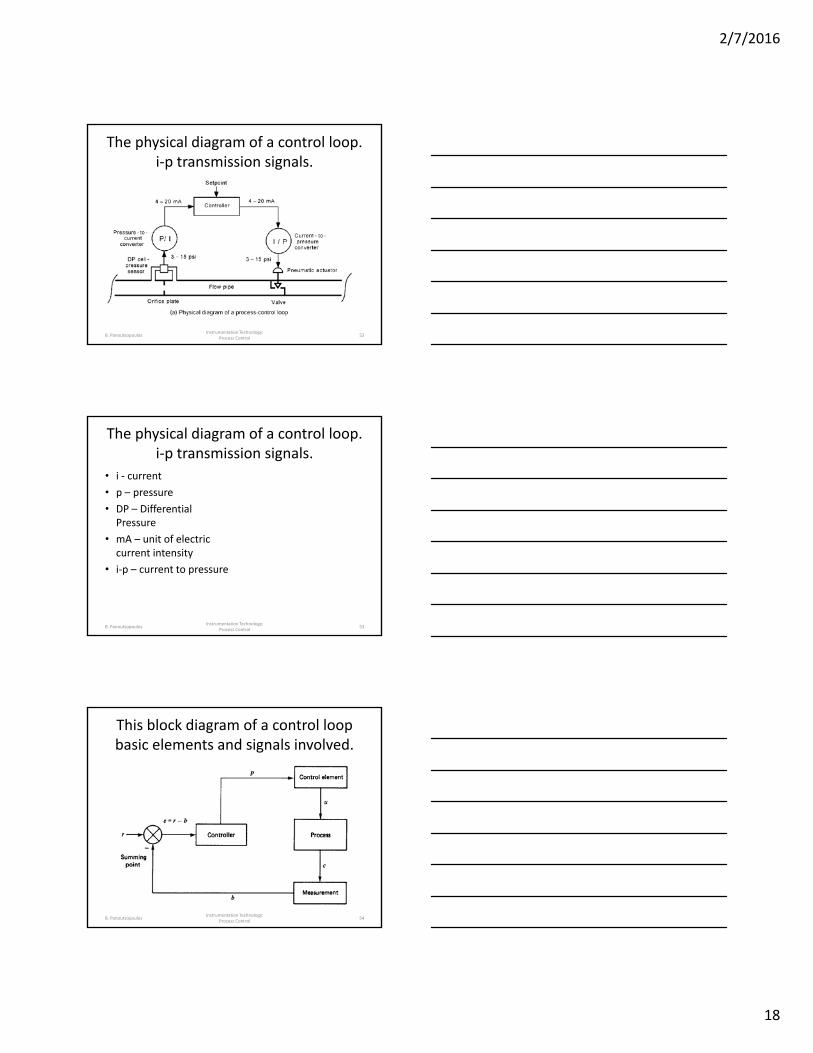
The physical diagram of a control loop. i‐p transmission signals.
Instrumentation Technology: Process Control
52B. Panoutsopoulos
The physical diagram of a control loop. i‐p transmission signals.
• i ‐ current
• p – pressure
• DP – Differential Pressure
• mA – unit of electric current intensity
• i‐p – current to pressure
Instrumentation Technology: Process Control
53B. Panoutsopoulos
This block diagram of a control loop basic elements and signals involved.
Instrumentation Technology: Process Control
54B. Panoutsopoulos
2/7/2016
19
These are the physical and block diagrams of a control loop
Instrumentation Technology: Process Control
55B. Panoutsopoulos
The physical diagram of a control loop. i‐p transmission signals.
Instrumentation Technology: Process Control
56B. Panoutsopoulos
Elements of Open‐ and Closed‐Loop Systems
• Common terms:
– Controlled variable or process variable
– Measured variable
– Measurement device
– Feedback signal
– Set‐point
– Error detector
– Error signal
– Controller
– Actuator
– Manipulated variable
– Manufacturing process
– Disturbance
B. PanoutsopoulosInstrumentation Technology:
Process Control57
2/7/2016
20
Open‐loop block diagramelements, input/output signals, and
signal direction
Instrumentation Technology: Process Control
58B. Panoutsopoulos
Closed‐loop block diagramelements, input/output signals, and
signal direction
Instrumentation Technology: Process Control
59B. Panoutsopoulos
Instrumentation Technology: Process Control
60B. Panoutsopoulos
2/7/2016
21
Feedback Control
• Error must exist before some corrective action can be made
• Causes of errors:
– The set‐point is changed
– A disturbance appears
– The load demand varies
• Signals may be positive or negative
Instrumentation Technology: Process Control
61B. Panoutsopoulos
Practical Feedback ApplicationHeat exchanger
Instrumentation Technology: Process Control
62B. Panoutsopoulos
Dynamic Response of a Closed‐Loop System
• Dynamic response:
– Measure of loop’s corrective action
• Factors:
– Response time
– Time duration
– Static inertia of controlled variable
– Leads to pure lag
– Dead time
Instrumentation Technology: Process Control
63B. Panoutsopoulos
2/7/2016
22
Feed‐Forward Control
• Prevent errors from occurring
• Minimize not prevent
• Also use feedback control
• Typically used only in critical applications within the plant
B. PanoutsopoulosInstrumentation Technology:
Process Control64
Feed‐forward control of a temperature control system
Instrumentation Technology: Process Control
65B. Panoutsopoulos
Feed‐forward control loop with a feedback control loop
Instrumentation Technology: Process Control
66B. Panoutsopoulos
2/7/2016
23
PRRACTICE
Instrumentation Technology: Process Control
67B. Panoutsopoulos
Process Operation
• A boiler operator is responsible for calibrating the instruments used to control a boiler.
Instrumentation Technology: Process Control
68B. Panoutsopoulos
Process Operation
•An heating, ventilation, and air conditioning (HVAC) technician measures airflow to troubleshoot an air‐handling system.
Instrumentation Technology: Process Control
69B. Panoutsopoulos
2/7/2016
24
Process Operation
•An electrician is often required to trouble‐shoot electrical systems related to instrument systems.
Instrumentation Technology: Process Control
70B. Panoutsopoulos
Process Operation
• Pneumatic controllers have visible internal components that make it easy to see how they work.
• Modern digital controllers are more versatile and reliable, but the internals are not as easy to see and understand.
Instrumentation Technology: Process Control
71B. Panoutsopoulos
Process Operation
•A modern transmitter can receive inputs from several types of instruments and sends signals in both digital and analog formats.
Instrumentation Technology: Process Control
72B. Panoutsopoulos
2/7/2016
25
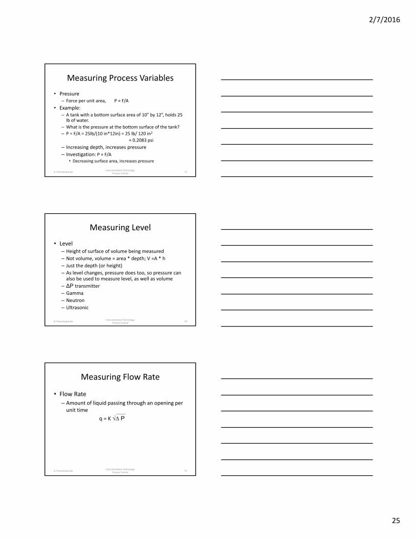
Measuring Process Variables
• Pressure– Force per unit area, P = F/A
• Example:– A tank with a bottom surface area of 10” by 12”, holds 25 lb of water.
– What is the pressure at the bottom surface of the tank?
• Level– Height of surface of volume being measured
– Not volume, volume = area * depth; V =A * h
– Just the depth (or height)
– As level changes, pressure does too, so pressure can also be used to measure level, as well as volume
– ΔP transmitter
– Gamma
– Neutron
– Ultrasonic
Instrumentation Technology: Process Control
74B. Panoutsopoulos
Measuring Flow Rate
• Flow Rate
– Amount of liquid passing through an opening per unit time
q = K √∆ P
Instrumentation Technology: Process Control
75B. Panoutsopoulos
2/7/2016
26
Standards organizations
•There are many industry and standards organizations that influence production operations.
Instrumentation Technology: Process Control
76B. Panoutsopoulos
SYNOPSIS
Instrumentation Technology: Process Control
77B. Panoutsopoulos
Functions and Elements in an Automatic Control System
Instrumentation Technology: Process Control
78B. Panoutsopoulos
2/7/2016
27
Process Control Term Definitions Summary
• A control system is a system of integrated elements whose function is to maintain a process variable at a desired value or within a desired range of values.
• Control system input is the stimulus applied to a control system from an external source to produce a specified response from the control system.
• Control system output is the actual response obtained from a control system.• An open‐loop control system is one in which the control action is independent of
the output.• A closed‐loop control system is one in which control action is dependent on the
output.• Feedback is information in a closed‐loop control system about the condition of a
process variable.• A controlled variable is the process variable that is maintained at a specified value
or within a specified range.• A manipulated variable is the process variable that is acted on by the control
system to maintain the controlled variable at the specified value or within the specified range.
Instrumentation Technology: Process Control
79B. Panoutsopoulos
Process Control
•A low‐water fuel cutoff is a level‐measuring device that shuts down a boiler when the water level drops below the lowest allowed level.
Instrumentation Technology: Process Control
80B. Panoutsopoulos
Process Control
•Process automation refers to processes involving batch and continuous flow of liquids, gases, and bulk solids.
Instrumentation Technology: Process Control
81B. Panoutsopoulos
2/7/2016
28
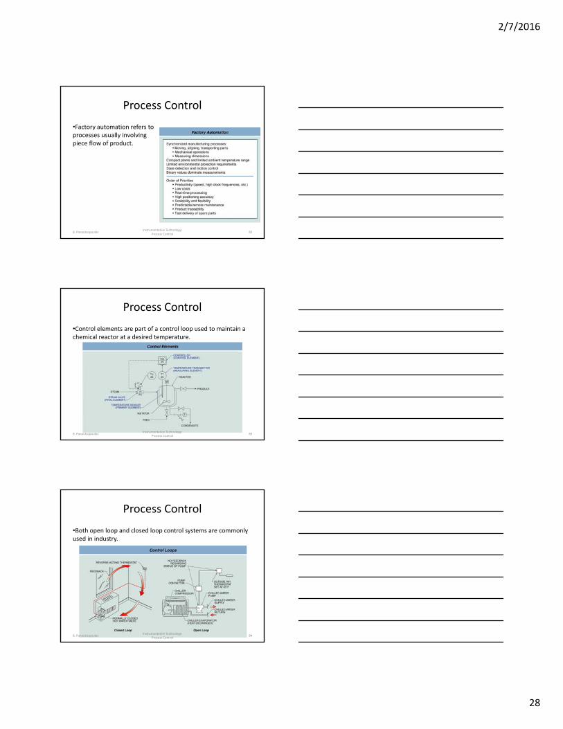
Process Control
•Factory automation refers to processes usually involving piece flow of product.
Instrumentation Technology: Process Control
82B. Panoutsopoulos
Process Control
•Control elements are part of a control loop used to maintain a chemical reactor at a desired temperature.
Instrumentation Technology: Process Control
83B. Panoutsopoulos
Process Control
•Both open loop and closed loop control systems are commonly used in industry.
Instrumentation Technology: Process Control
84B. Panoutsopoulos
2/7/2016
29
APPENDIX: HYSTERESIS
Instrumentation Technology: Process Control
85B. Panoutsopoulos
Process Control: Hysteresis
•Hysteresis is the property of a control element that results in different performance when a measurement is increasing than when the measurement is decreasing.
Instrumentation Technology: Process Control
86B. Panoutsopoulos
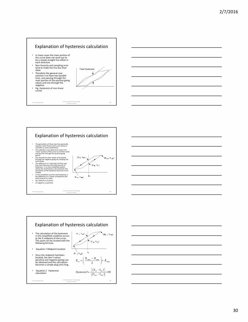
Explanation of hysteresis calculation
• Hysteresis is the measurement of the difference in Y offset of the values generated by the transducer as it measures in a positive going direction, and the same values as the transducer measures back down toward zero( the negative going values).
• Fig.: General hysteresis
Instrumentation Technology: Process Control
87B. Panoutsopoulos
2/7/2016
30
Explanation of hysteresis calculation
• In many cases the main portion of this curve does not work out to be a simple straight line offset in each direction.
• Non‐linearity and sampling error tend to make the line less than ideal.
• Therefore the general case solution is to have two parallel lines, one passing through the main portion of the positive going values and one through the negative.
• Fig. Hysteresis of non‐linear curves
Instrumentation Technology: Process Control
88
Total Hysteresis
B. Panoutsopoulos
Explanation of hysteresis calculation
• The generation of these two lines generally requires some finesse and is not nearly as scientific as some would think.
• The calibrator must determine where the “main” portion of the curve is and then what line best fits through the positive going points.
• The second line then needs to be placed through the negative going set, keeping the same slope.
• The difference in Y intercept of these two lines then becomes the total amount of hysteresis. In a more simplified system, where the nonlinearity is less dramatic the calculation of the hysteresis becomes much simpler.
• In this simplified case the total hysteresis is the difference in y values compared to the total amount of y span.
• Fig. Definition of points.• (n‐negative, p‐positive)
Instrumentation Technology: Process Control
89B. Panoutsopoulos
Explanation of hysteresis calculation
• The calculation of the hysteresis in this simplified condition occurs at the X midpoint of the curve. This point can be located with the following formula.
• Equation 1 Midpoint location
• Once the midpoint had been located, the two Y values (positive and negative going) can be obtained and the calculation becomes a simple plug and chug.
• Equation 2 Hysteresis calculation
Instrumentation Technology: Process Control
90
max minmin2m
X XX X
max min
Hysteresis% 100mn mpY Y
Y Y
B. Panoutsopoulos
2/7/2016
31
Explanation of hysteresis calculation
• In some complex situations the curves may be so close that it is nearly impossible to differentiate, or the linearity is so bad that it simply swamps the amount of hysteresis.
• In these conditions a hysteresis of 0 is possible. • Another unusual condition is where the negative going slope has so
much hysteresis that it overlaps the positive going transition. • Under these conditions the slopes of the positive and negative going
portions of the curve have Y intercept values that are extremely large. • Under these conditions the calculation, made either graphically or
mathematically, using the difference between the slopes, could easily end up with a hysteresis of larger than 100%.
• Generally these types of huge hysteresis conditions are intentionally created for fine/course control inputs.