252
INSTRUMENTATION AND CONTROL SYSTEMS Course Code: AME019 Regulation : R16 Dr. P Raghavulu M V Aditya Nag COURSE HANDOUT 1
INSTRUMENTATION AND
CONTROL SYSTEMS
Course Code: AME019
Regulation : R16
Dr. P Raghavulu
M V Aditya Nag
COURSE HANDOUT
1
Definition
Basic principles of Measurement
Measurement systems
Static performance characteristics
Dynamic performance characteristics
Sources of errors, classification, Elimination
.
UNIT-I SYLLABUS
2
• The Instrumentation is the technology of makingmeasurements and it implies the application ofinstruments for sensing, measurement, control andmonitoring physical variables.
• Instrumentation is a multi disciplinary subject, itsdifferent aspects are based on the subject areas ofphysics, system dynamics, thermo-fluid mechanics andelectrical principles.
• The division of engineering science which deals withmeasuring techniques, devices and their associatedproblems is called instrumentation.
INSTRUMENTATION
3
Measurement is the act , or result of a quantitativecomparison between a predetermined standard and ameasurand (input).
The Measurement of a given quantity is essentially anact or result of comparison between a quantity whosemagnitude (amount) is unknown, with a similarquantity whose magnitude (amount) is known, thelatter quantity being called a Standard.
Quantities like pressure, temperature, displacement,fluid flow and associated parameters, acoustics andrelated parameters, and fundamental quantities likemass, length, and time are typical of those which arewithin the scope of mechanical measurements.
MEASUREMENT
4

MEASUREMENT
• Measurement is the result of an opinion formed by one ormore observers about their relative size or intensity ofsome physical quantity.
• The opinion is formed by the observer after comparing theobject with a quantity of some kind chosen as a unit calledstandard.
• The result of measurement is expressed by a numberrepresenting the ratio of unknown quantity to thestandard.
5
.
It is more appropriate to use the term Measurementof Mechanical Quantities rather than mechanicalmeasurements .
(i) All mechanical quantities are not measured by
mechanical means.
(ii)And, measurement of mechanical quantities, in
modern technology, involves the use of electrical
and electronic techniques.
MEASUREMENT contd..
6
.
7
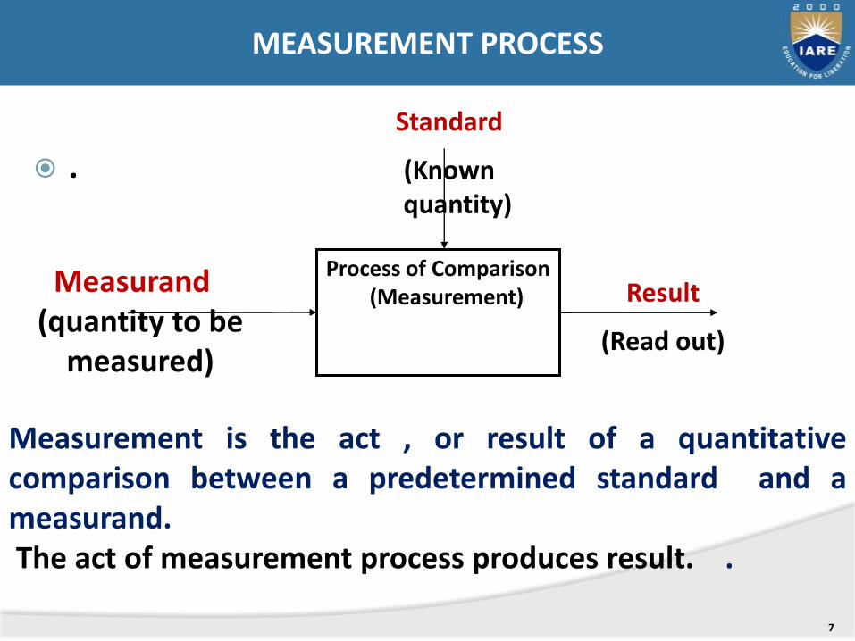
Process of Comparison (Measurement)
Standard
(Known quantity)
Result
(Read out)
Measurand(quantity to be
measured)
Measurement is the act , or result of a quantitativecomparison between a predetermined standard and ameasurand.The act of measurement process produces result. .
MEASUREMENT PROCESS
The basic requirements are:
(i) The standard used for comparison purposes must be
accurately defined and should, be commonly acceptable.
(ii) The standard must be of the same character as the measurand
(the unknown quantity or the quantity under measurement)
and is prescribed and defined by a legal or recognized agency
or organization like National Bureau of Standards (NBS) or the
International Organization of Standards (ISO), the American
National Standards institute (ANSI)
(iii)The apparatus used and the method adopted for the purposes
of comparison must be provable.
BASIC REQUIREMENTS OF MEASUREMENT
8
1. Direct Methods. The unknown quantity is directly compared against a standard. The result is expressed as a numerical number and a unit. The standard, in fact, is a physical embodiment of a unit.
Direct methods are quite common for the measurement of physical quantities like length, mass and time.
As direct measurement involve human factors are less accurate, less sensitive
The direct methods may not always be possible, feasible and practicable.
Hence direct methods are not preferred and are less commonly used.
METHODS OF MEASUREMENT
9
2. Indirect Methods: The value of the physical parameter(measurand) is more generally determined by indirectcomparison with secondary standards throughcalibration.
In direct method of measurement system consists of atransducing element which converts the quantity tobe measured into an analogous signal. The analogoussignal is then processed by some intermediate meansand is then fed to the end devices which present theresults of the measurement.
METHODS OF MEASUREMENT
10
2. Indirect Methods of measurement.
Based upon the complexity of the measurement system
the measurements are generally grouped into three
categories.
2.1) primary measurements
2.2) secondary measurements
2.3) Tertiary measurements.
METHODS OF MEASUREMENT
11
• A primary measurement is one that can be made by direct observation without involving any conversion (translation) of the measured quantity into length.
• The sought value of a physical parameter is determined by comparing it directly with reference standards.
• Typical examples of primary measurements are:
A. Determining the length of an object with a meter rod.
B. The matching of two colors, such as when judging the color of red hot metals .
2.1 PRIMARY MEASUREMENT
12
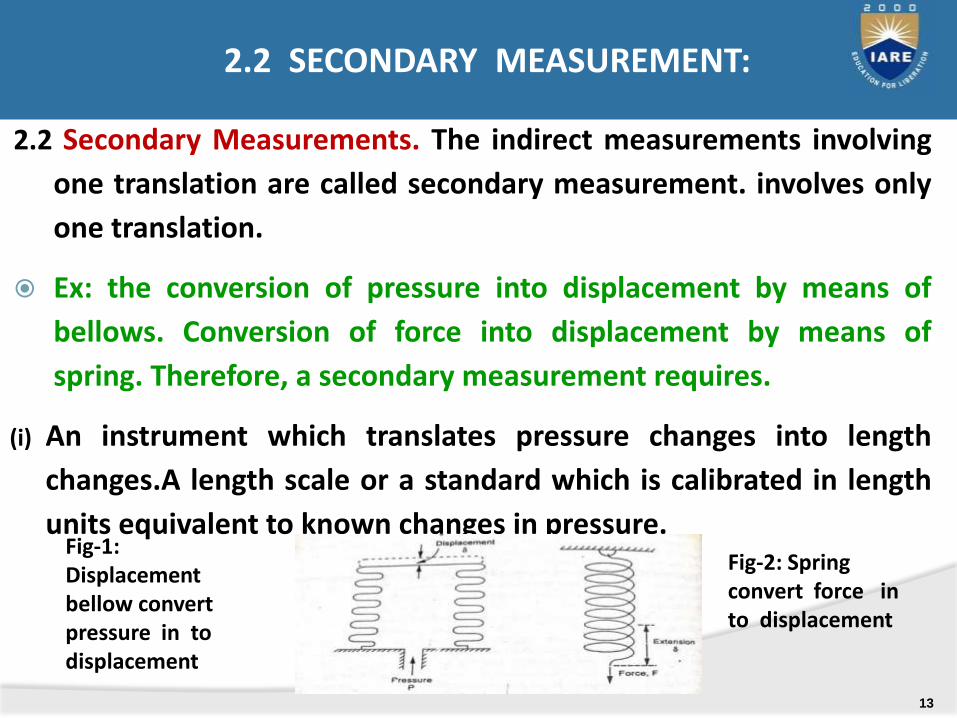
2.2 Secondary Measurements. The indirect measurements involving
one translation are called secondary measurement. involves only
one translation.
Ex: the conversion of pressure into displacement by means of
bellows. Conversion of force into displacement by means of
spring. Therefore, a secondary measurement requires.
(i) An instrument which translates pressure changes into length
changes.A length scale or a standard which is calibrated in length
units equivalent to known changes in pressure.Fig-1: Displacement bellow convert pressure in to displacement
Fig-2: Spring convert force in to displacement
2.2 SECONDARY MEASUREMENT:
13
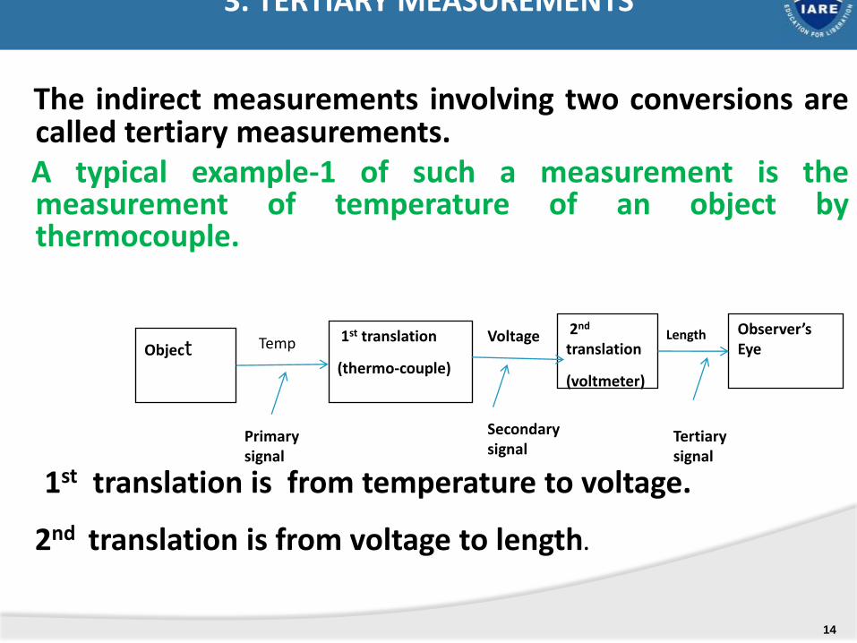
The indirect measurements involving two conversions arecalled tertiary measurements.A typical example-1 of such a measurement is themeasurement of temperature of an object bythermocouple.
1st translation is from temperature to voltage.
2nd translation is from voltage to length.
Object1st translation
(thermo-couple)
Observer’s Eye
2nd
translation
(voltmeter)
Temp Voltage Length
Tertiary signal
Secondary signal
Primary signal
3. TERTIARY MEASUREMENTS
14
.
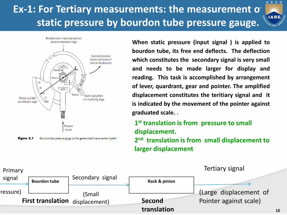
When static pressure (input signal ) is applied to
bourdon tube, its free end deflects. The deflection
which constitutes the secondary signal is very small
and needs to be made larger for display and
reading. This task is accomplished by arrangement
of lever, quardrant, gear and pointer. The amplified
displacement constitutes the teritiary signal and it
is indicated by the movement of the pointer against
graduated scale. .
bBourdon tube Rack & pinion
Primary signal
Pressure)
Secondary signal
(Small displacement)
Tertiary signal
(Large displacement ofPointer against scale)First translation Second
translation
1st translation is from pressure to small displacement. 2nd translation is from small displacement to larger displacement
Ex-1: For Tertiary measurements: the measurement of a static pressure by bourdon tube pressure gauge.
15
1. STATIC CHARACTERISTICS 2. DYNAMIC CHARACTERISTICS
1. STATIC CHARACTERISTICS: The characteristics which describe the performance of
measuring instruments when subjected to low frequencyinputs or DC inputs are referred to as staticcharacteristics
In some of applications the parameter of interest ismore or less constant or varies very slowly with time.Measurement of such applications are called staticmeasurement
PERFORMANCE CHARACTERISTICS OF ANINSTRUMENTS : are classified as
16

STATIC CHARACTERISTICS OF AN INSTRUMENT :are as follows
1.1 Accuracy1.2 Error1.3 Reproducibility1.4 Drift1.5 Sensitivity1.6 Dead Zone 1.7 Precision1.8 Linearity1.9 Threshold1.10 Hysteresis1.11 Resolution1.12 Stability 1.13 Range and Span
17
2. DYNAMIC PERFORMANCE CHARACTERISTICS OF INSTRUMENT contd…
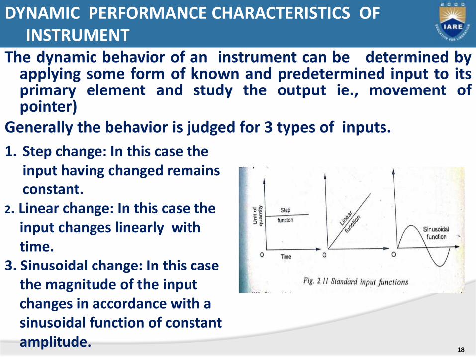
The dynamic behavior of an instrument can be determined byapplying some form of known and predetermined input to itsprimary element and study the output ie., movement ofpointer)
Generally the behavior is judged for 3 types of inputs.
1. Step change: In this case the input having changed remains constant.
2. Linear change: In this case the input changes linearly with time.
3. Sinusoidal change: In this case the magnitude of the input changes in accordance with a sinusoidal function of constant amplitude.
DYNAMIC PERFORMANCE CHARACTERISTICS OF INSTRUMENT
18
The dynamic characteristics of an instrument are as follows:
2.1 Speed of response
2.2 Measurement Lag
2.3 Fidelity
2.4 Dynamic error
2.5 Dynamic range
2.6 Band width
2.7 Setting time
2.8 Time constant.
2. DYNAMIC PERFORMANCE CHARACTERISTICS OF INSTRUMENT
19
• There is another way in which instruments or
measurement systems may be classified.
• This classification is based upon the functions they
perform.
• The three main functions are explained below:
1) Indicating Function.
2) Recording Function.
3) Controlling Function.
FUNCTIONS OF INSTRUMENTS AND MEASUREMENT SYSTEMS
20
(i) Monitoring of processes and operations.
(ii)Control of processes and operations.
(iii) and Experimental Engineering analysis.
•
APPLICATIONS OF MEASUREMENT SYSTEMS
21
Generalized configuration and functional description of measuring instruments-Examples
Sources of error,Classification & elimination of error
.
22
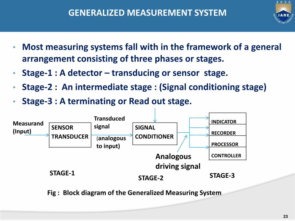
• Most measuring systems fall with in the framework of a general arrangement consisting of three phases or stages.
• Stage-1 : A detector – transducing or sensor stage.
• Stage-2 : An intermediate stage : (Signal conditioning stage)
• Stage-3 : A terminating or Read out stage.
SENSOR
TRANSDUCER
SIGNAL
CONDITIONER
INDICATOR
RECORDER
PROCESSOR
CONTROLLER
Measurand(Input)
Transducedsignal
(analogous to input)
Analogous driving signal
STAGE-1STAGE-2 STAGE-3
Fig : Block diagram of the Generalized Measuring System
GENERALIZED MEASUREMENT SYSTEM
23
T • [
Sensor transducer
Piston/ or
cylinder
(Pressure to
Force)
Spring
(Force to
Displacement)
Read out(scale & index)
InputPressure
Singalconditioning
(None)
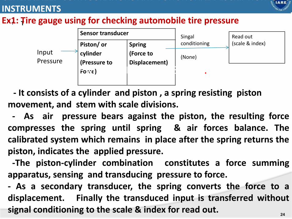
- It consists of a cylinder and piston , a spring resisting piston movement, and stem with scale divisions.- As air pressure bears against the piston, the resulting force
compresses the spring until spring & air forces balance. Thecalibrated system which remains in place after the spring returns thepiston, indicates the applied pressure.-The piston-cylinder combination constitutes a force summing
apparatus, sensing and transducing pressure to force.- As a secondary transducer, the spring converts the force to adisplacement. Finally the transduced input is transferred withoutsignal conditioning to the scale & index for read out.
GENERAL IZED CONFIGURATIONS AND FUNCTIONAL DESCRIPTION OF INSTRUMENTSEx1: Tire gauge using for checking automobile tire pressure
APPLICATIONS OF MEASUREMENT SYSTEMS.
24

25
BOURDON PRESSURE GAUGE
.
A generalized configuration in instruments and
measurement systems which brings out a significant
input-output relationship present in them is shown in
Figure. Input quantities are classified into three
categories:
(i) Desired inputs.
(ii)Interfering inputs.
(iii)Modifying inputs.
• .
AN INPUT-OUTPUT CONFIGURATIONS OF MEASURING INSTRUMENTS AND MEASUREMENT SYSTEMS.
26
27
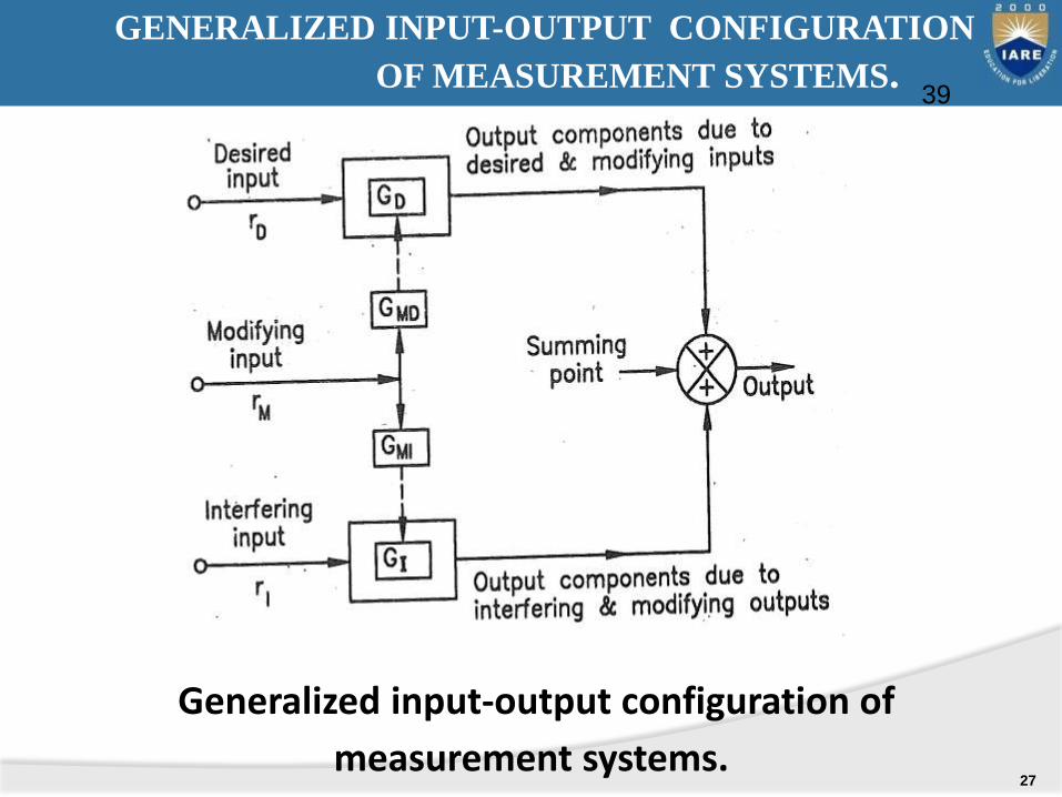
Generalized input-output configuration of
measurement systems.
39
GENERALIZED INPUT-OUTPUT CONFIGURATION
OF MEASUREMENT SYSTEMS.
• Error = Reading of standard value – measured value
• The accuracy and precision of an instrument dependsupon its design, the material used and workmanshipthat goes into making the instrument.
• The choice of an instrument for a particularapplication depends upon the accuracy desired.
• If only a fair degree of accuracy is desired , it is noteconomical to use expensive meter and skill for themanufacture of the instruments.
• But an instrument used for an application requiring ahigh degree of accuracy has to use expensive and ahighly skilled workmanship.
ERRORS
28
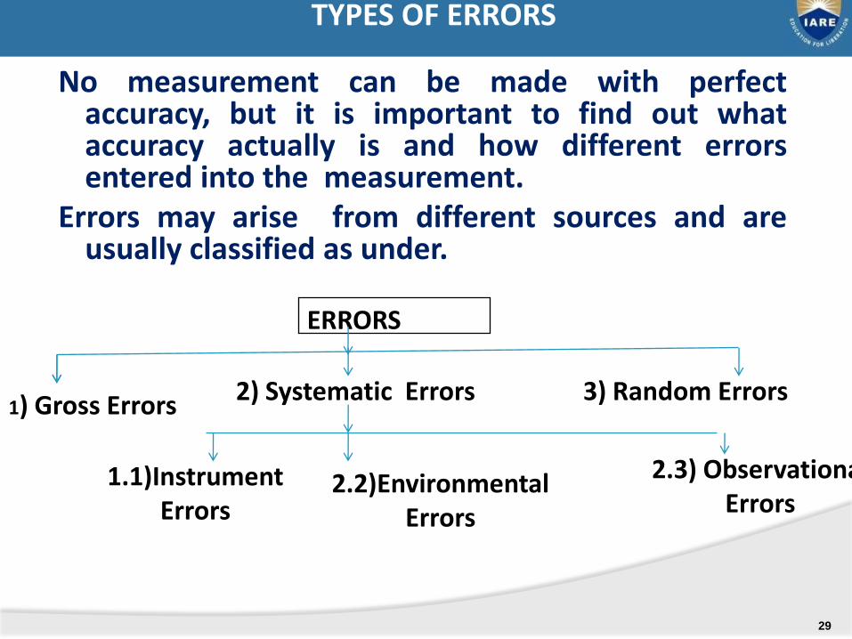
TYPES OF ERRORSNo measurement can be made with perfect
accuracy, but it is important to find out whataccuracy actually is and how different errorsentered into the measurement.
Errors may arise from different sources and areusually classified as under.
ERRORS
1) Gross Errors 3) Random Errors2) Systematic Errors
1.1)Instrument Errors
2.3) Observational Errors
2.2)Environmental Errors
TYPES OF ERRORS
29
1. Noise: it is defined as any signal that does not conveyuseful information . The noise or signal disturbancescontribute to the uncertainty of measurement.
Noise may originate either
• At the primary sensing device
• In a communication channel
• In the indicating element of the system
• Noise can be reduced to a maximum level throughfiltering, careful selection of components,shielding and isolation of the entire measuringsystem.
2. Response time: measuring system can notimmediately indicate the input signal applied to it. Thisfactor contributes to uncertainty. ( mercurythermometer)
SOURSES OF ERRORS /(FACTORS CONTRIBUTINGFOR UNCERTAINTY OF MEASUREMENT)
30
3. Design limitations: In the design of an instrumentsthere are certain inevitable factors which lead touncertainty of measurement.
4. Effects of friction in the instrumentmovement:
5. Effect of resolving power : The ability ofobserver to distinguish between nearly equaldivisions.
6. Energy exchanged by interaction : when everenergy required for operating the measuringsystem is extracted from the measurand, thevalue of latter is altered to a grater or lesserextent.
SOURSES OF ERRORS /(FACTORS CONTRIBUTINGFOR UNCERTAINTY OF MEASUREMENT) Contd..
31
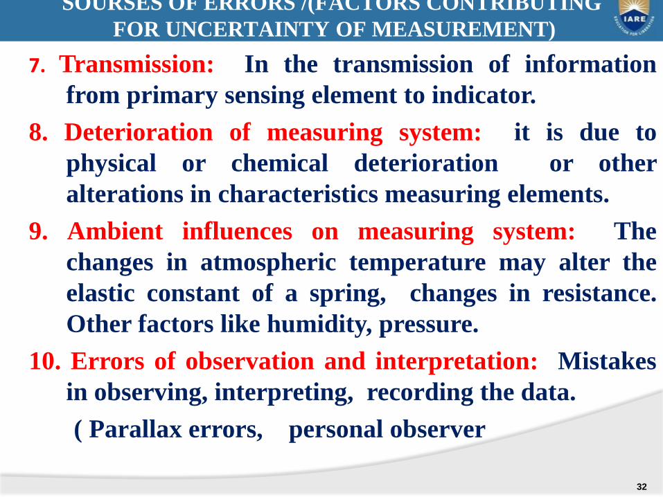
7. Transmission: In the transmission of information
from primary sensing element to indicator.
8. Deterioration of measuring system: it is due to
physical or chemical deterioration or other
alterations in characteristics measuring elements.
9. Ambient influences on measuring system: The
changes in atmospheric temperature may alter the
elastic constant of a spring, changes in resistance.
Other factors like humidity, pressure.
10. Errors of observation and interpretation: Mistakes
in observing, interpreting, recording the data.
( Parallax errors, personal observer
SOURSES OF ERRORS /(FACTORS CONTRIBUTING
FOR UNCERTAINTY OF MEASUREMENT)
32
This unit covers
• MEASUREMENT OF DISPLACEMENT
• MEASUREMENT OF TEMPERATURE
• MEASUREMENT OF PRESSURE.
UNIT-II
33
MEASUREMENT OF DISPLACEMENT
As per syllabus we focus on following.
Theory and construction of various transducers to measure displacement.
•Piezo electric transducer
•Inductive transducer
•Capacitance transducer
•Resistance transducer
•Ionization transducer
•Photo Electric transducer
•Calibration procedure
34
A transducer is a device which senses the physical variable to be measured and converts into a suitable signal ( voltage or current)
A device to convert the quantity or phenomenon to be measured into a voltage or current, which can be observed on an oscilloscope, read on a meter or recorded on a chart
Ex: - Pressure transducer
- Temperature transducers :( RTD, Thermistor,
Thermocouple. Pyrometer)
TRANSDUCER
35
- Displacement transducers:
1)Variable resistance transducer, 2)LVDT 3)Capacitive, 4) variable Reluctance displacement transducer,
5) piezoelectric transducer,
6) Hall effect displacement transducer,
7) photoelectric transducer, 8)Ionization transducer, 9) LDR
36
TRANSDUCER
Examples of Displacement transducers:
1) Variable resistance transducer,
2) LVDT
3) Capacitive,
4) variable Reluctance displacement transducer,
5) piezoelectric transducer,
6) Hall effect displacement transducer,
7) photoelectric transducer,
8)Ionization transducer,
9) LDR
TRANSDUCER
37
1. Fundamental parameters : these include
a) Type of measurand (input)
b) Range of measurement
c) Required precision , which includes
- allowable non-linearity effects
- allowable dead-zone effects
- Frequency response
- Resolution
2. Environment : This includes conditions of
a) Ambient temperature
b) Corrosive or non-corrosive atmosphere
c) What shock and vibration to with stand
FACTORS ON WHICH TRASDUCER SELECTION DEPEND
38

FACTORS ON WHICH TRASDUCER SELECTION DEPEND
3. Physical conditions: These area) Room or available space to mount the transducer.b) Whether the measurement is static or dynamic.c) How much energy can be extracted from the input
to do measurement with out much loading.4)Compatibility with next stage: Transducer should be so
chosen so as to meet the requirements of next stage.a) Impedance matching.b) Excitation voltage matching.c) Sensitivity tolerance matching.
FACTORS ON WHICH TRASDUCER SELECTION DEPEND
39
FACTORS ON WHICH TRASDUCER SELECTION DEPEND
5) General requirements:
a) Ruggedness to withstand over loads
b) Linearity
c) Repeatability
d) Stability and reliability
e) Good dynamic response
f) Convenient instrumentation.
FACTORS ON WHICH TRASDUCER SELECTION DEPEND
40

Transducers are classified as follows:
1. Active and passive transducer and Passive transducer.
Active Transducer : The transducer which do not require any external excitation energy to provide their output are known as active transducer.
Example: Piezo electric transducer
Photo voltaic cell
Thermocouple
Moving coil generator
CLASSIFICATION OF TRANSDUCERS
41
1b) Passive transducer: The transducers which require an external excitation energy to provide their output are known as passive transducers.
Examples: - Resistance transducer
- Capacitive transducer
- Inductive transducer
- Hall-effect transducer
-Photo emissive cell
(Photo electric type transducer)
CLASSIFICATION OF TRANSDUCERS
42
2) On the basis of transduction principle used: the input variable to the transducer is being converted into resistance, capacitance or inductance value.
2a) Resistive transducers:Resistance thermometer, Potentiometer device,Resistance strain gauge, Thermistor,Photo conductive cell
2b) Capacitive transducers: Dielectric gauge,capacitor microphone, Variable capacitance
pressure gauge2c) Inductive transducers: Differential transformer type
transducer (LVDT, RVDT), Reluctance type transducer,
.
CLASSIFICATION OF TRANSDUCERS
43
3) Primary and secondary transducers:
3a) Primary transducer: is the first element in ameasurement system and it senses the physicalparameters (like temperature, pressure,displacement, force etc.) and converts them intoa mechanical parameter ( usually displacement)
These are mechanical type and electrical type
Ex: -pressure sensing elements (diaphragm, bellows,bourdon tube)
- solid rod expansion thermometers (Bimetallic strip)
- The cylindrical column of a load cell which convertsdisplacement in to strain
CLASSIFICATION OF TRANSDUCERS
44
3) Primary and secondary transducers:
3b) Secondary transducer: A transducer which is used asthe second element of a measurement system, toconvert the mechanical output of primary transducerinto an electrical quantity is known as secondarytransducer. Generally these are electrical typetransducers.
Example: -strain gauge
-LVDT (Linear variable differential
transformer).
CLASSIFICATION OF TRANSDUCERS
45
4) Analog and Digital transducers:
4a) Analog transducer: it is a transducer which produces an output in analog form or a form which is a continuous function of time. .
Example: -Thermistor
. - Thermocouple
- Strain gauge
- LVDT
4b) Digital transducer: It is a transducer which produces an output in digital form or in the form of pulses.
Example: Turbine flow meter.
CLASSIFICATION OF TRANSDUCERS
46
5) Transducers and Inverse Transducers:
5a) Transducer (Input transducers): a measuringdevice which measures and converts non-electricalquantity into electrical quantity is known astransducer. Such transducers are usually used in theinput stage of a system and hence they are alsoknown as input transducers
Example: - potentio meter
- Thermo couple
- LVDT
- Moving coil generator
CLASSIFICATION OF TRANSDUCERS
47
5) Transducers and Inverse Transducers:
5b) Inverse Transducer (output transducers): Ameasuring device which measures and converts anelectrical quantity into non-electrical quantity is knownas inverse transducer. Such transducers are usuallyplaced at the output stage of a measurement systemand hence they are also known as output transducers.Inverse transducers are used in feedback measuringsystems like servo-mechanism etc.
Example: - Piezo electrical crystal
-Data indicating and recordinginstruments ( Analog ammeter, Volt meter,pen recorders etc.)
CLASSIFICATION OF TRANSDUCERS
48
1a)Variable resistance transducer ( Potentio meter)
2a) Variable inductance transducer – LVDT(Linear Variable Differential Transducer)
3) Variable reluctance displacement transducer.
4a) linear Variable capacitance transducer
5) Piezo electric transducer
6) Light dependent Resistance (LDR)
7) Ionization transducer
ELECTRICAL TRANSDUCERS FOR LINEAR DISPLACEMENT MEASUREMENT
49

1b)Angular potentiometric displacement transducer
2b) Variable inductance transducer – RVDT
(Rotary variable differential transformer)
3b) Angular variable capacitance transducer
4) Hall-effect angular displacement transducer
5) Synchro’s and Resolver’s
ELECTRICAL TRANSDUCERS FOR ANGULAR DISPLACEMENT MEASUREMENT
50
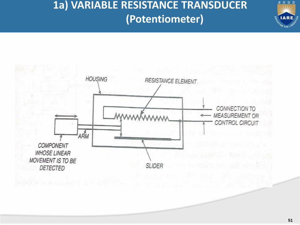
1a) VARIABLE RESISTANCE TRANSDUCER (Potentiometer)
51
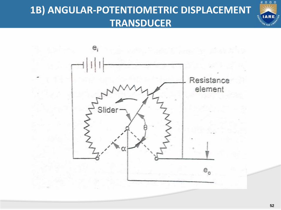
1B) ANGULAR-POTENTIOMETRIC DISPLACEMENT TRANSDUCER
52
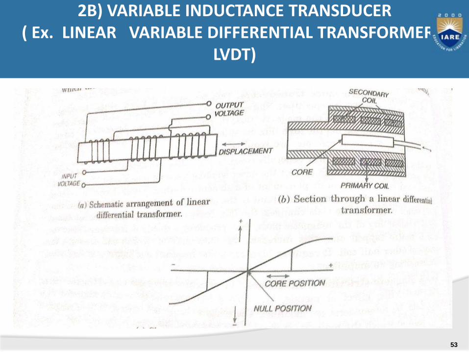
2B) VARIABLE INDUCTANCE TRANSDUCER ( Ex. LINEAR VARIABLE DIFFERENTIAL TRANSFORMER –
LVDT)
53
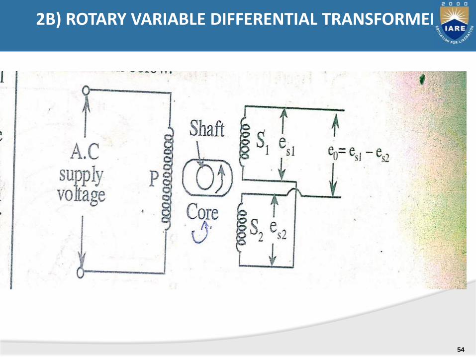
2B) ROTARY VARIABLE DIFFERENTIAL TRANSFORMER
54
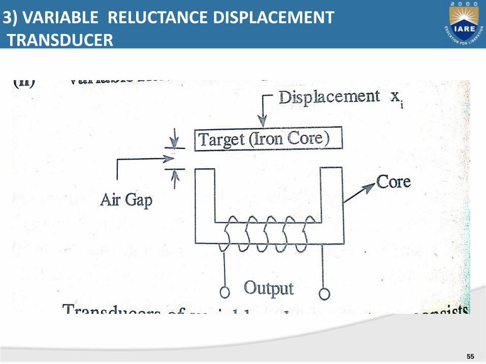
3) VARIABLE RELUCTANCE DISPLACEMENT TRANSDUCER
55
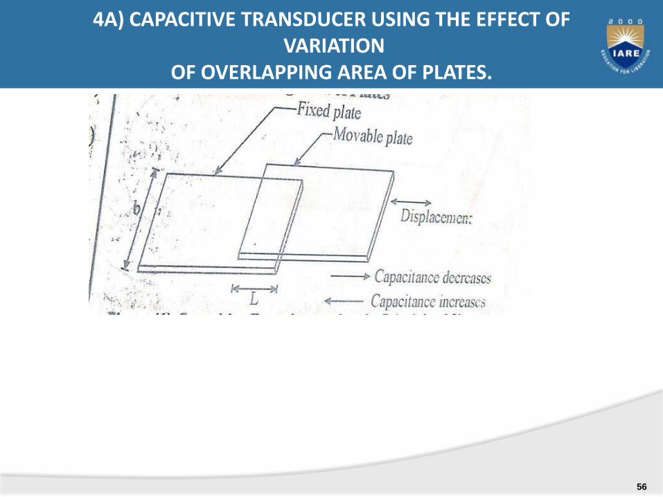
4A) CAPACITIVE TRANSDUCER USING THE EFFECT OFVARIATION
OF OVERLAPPING AREA OF PLATES.
56
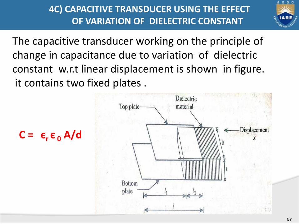
C = єr є 0 A/d
The capacitive transducer working on the principle of change in capacitance due to variation of dielectric constant w.r.t linear displacement is shown in figure.it contains two fixed plates .
4C) CAPACITIVE TRANSDUCER USING THE EFFECTOF VARIATION OF DIELECTRIC CONSTANT
57
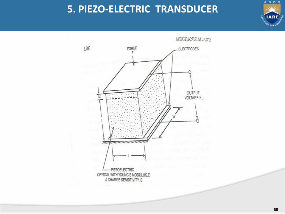
5. PIEZO-ELECTRIC TRANSDUCER
58
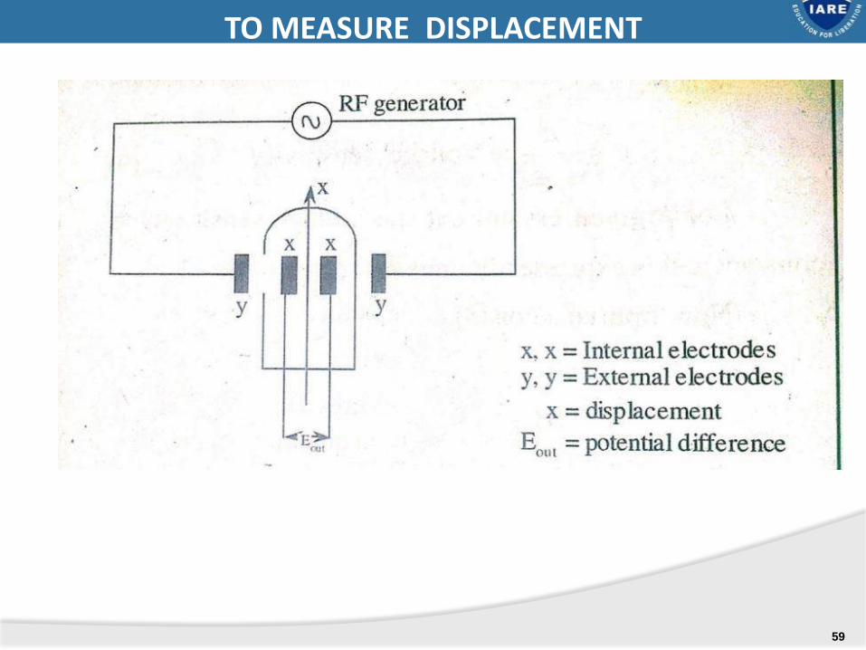
IONIZATION TRANSDUCER: TO MEASURE DISPLACEMENT
59

LIGHT DEPENDENT RESITOR (LDR):
60
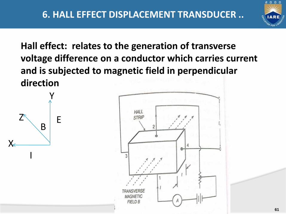
Hall effect: relates to the generation of transverse voltage difference on a conductor which carries current and is subjected to magnetic field in perpendicular direction
Y
Z
XI
EB
6. HALL EFFECT DISPLACEMENT TRANSDUCER ..
61

.
HALL-EFFECT DISPLACEMENT TRANSDUCER
62
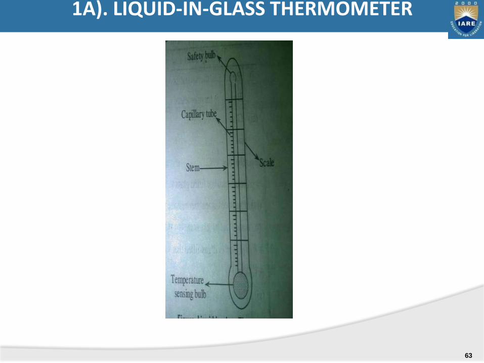
1A). LIQUID-IN-GLASS THERMOMETER
63
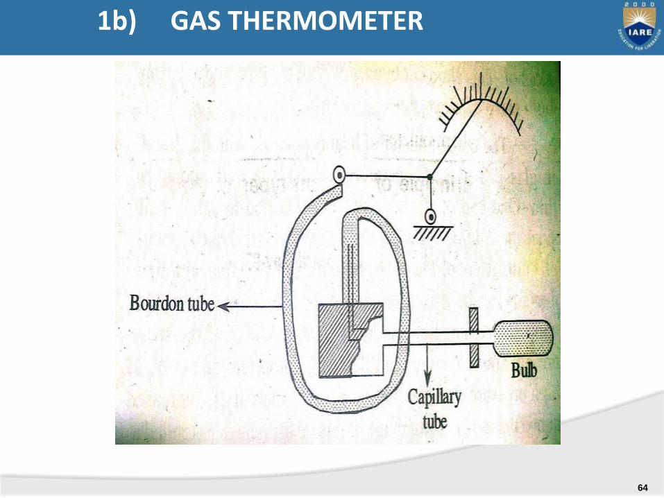
1b) GAS THERMOMETER
64

Non-volatile liquid
1c) VAPOUR PRESSURE THERMOMETER
65
.
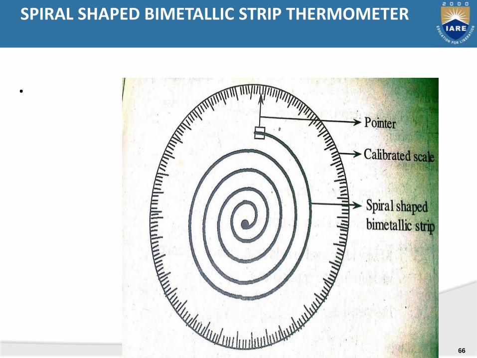
SPIRAL SHAPED BIMETALLIC STRIP THERMOMETER
66
:
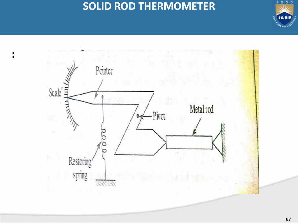
SOLID ROD THERMOMETER
67
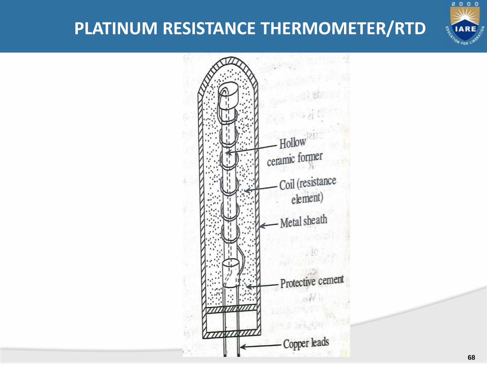
PLATINUM RESISTANCE THERMOMETER/RTD
68
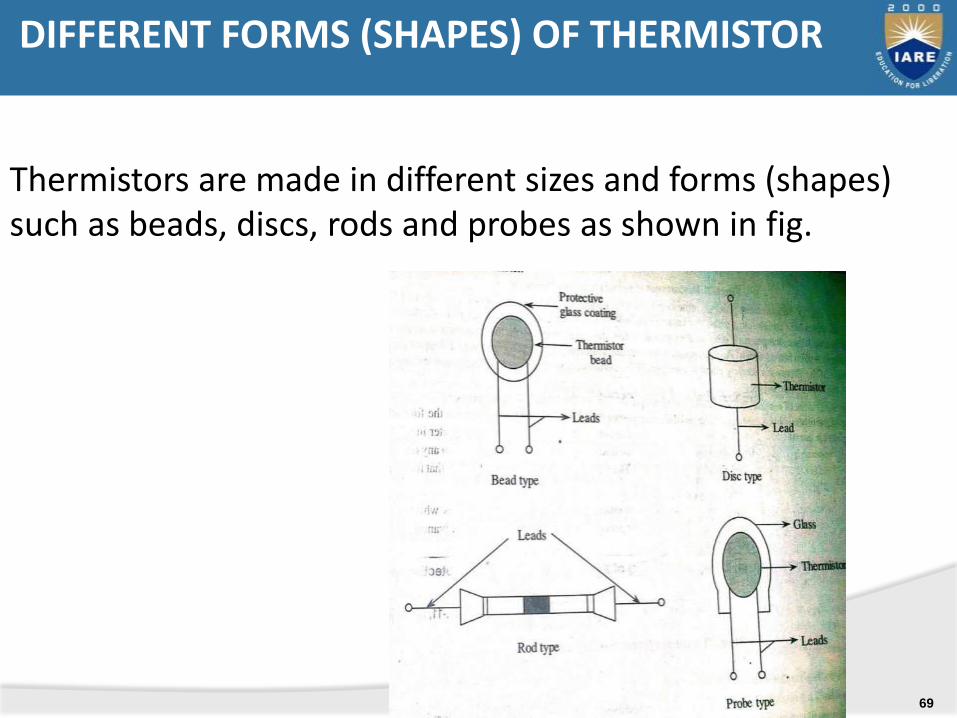
Thermistors are made in different sizes and forms (shapes) such as beads, discs, rods and probes as shown in fig.
DIFFERENT FORMS (SHAPES) OF THERMISTOR
69
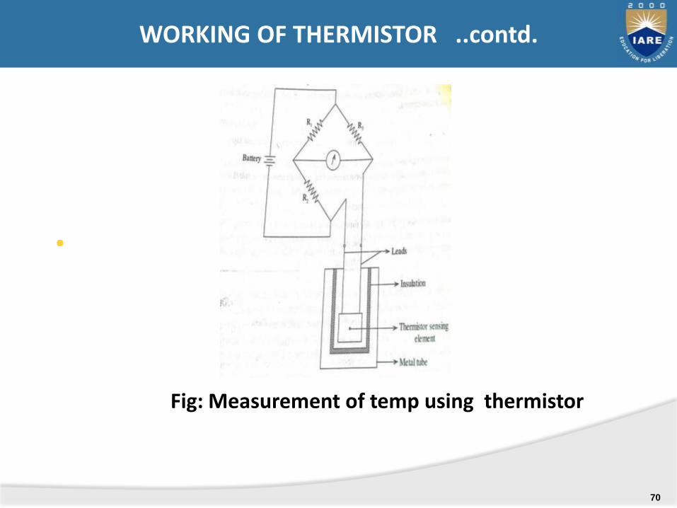
.
Fig: Measurement of temp using thermistor
WORKING OF THERMISTOR ..contd.
70
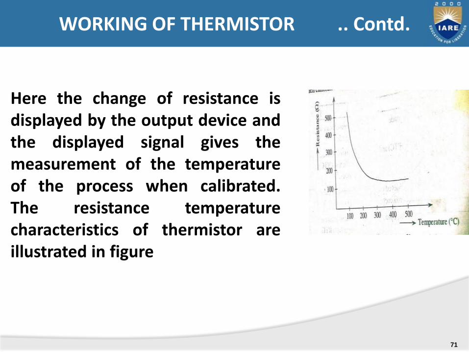
…
Here the change of resistance isdisplayed by the output device andthe displayed signal gives themeasurement of the temperatureof the process when calibrated.The resistance temperaturecharacteristics of thermistor areillustrated in figure
WORKING OF THERMISTOR .. Contd.
71

RTD
1. RTD are made of pure metals
2. It has +ve temp. Coefficient
3. RTD has low accuracy
4. Used for greater temp range up to 6000 C
5. RTD allow smaller cable lengths
6. Slow output response
7. Used in industrial installation application
8. Good stability
9. These are expensive
10. Low amount of heating
THERMISTOR
1) Thermistors are made up of ceramic or polymer materials.
2) It has –ve temp. coefficient3) Thermistors have good accuracy4) Used for lower temp range up to 1300
C5) It allows larger cable length6) Fast output response7) Used in home appliances
8) Less stable than RTD9) These are in expensive10) High amount of self heating
DISTIGUISH BETWEEN RTD & THERMISTOR
72
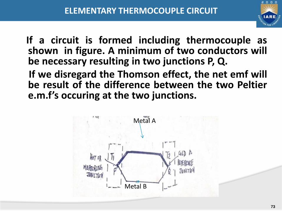
If a circuit is formed including thermocouple asshown in figure. A minimum of two conductors willbe necessary resulting in two junctions P, Q.If we disregard the Thomson effect, the net emf willbe result of the difference between the two Peltiere.m.f’s occuring at the two junctions.
Metal A
Metal B
ELEMENTARY THERMOCOUPLE CIRCUIT
73
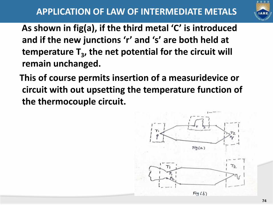
As shown in fig(a), if the third metal ‘C’ is introduced and if the new junctions ‘r’ and ‘s’ are both held at temperature T3, the net potential for the circuit will remain unchanged.
This of course permits insertion of a measuridevice or circuit with out upsetting the temperature function of the thermocouple circuit.
APPLICATION OF LAW OF INTERMEDIATE METALS
74

-
As shown in fig(b), if the third metal ‘C’ may be introduced at either a measuring or reference junction, so long as couples P1 and P2 are maintained at the same temperature T1.
this makes possible the use of joining metals, such as soft or hard solder in fabricating the thermocouples.
APPLICATION OF LAW OF LAW OF INTERMEDIATE METALS
75
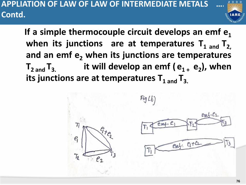
If a simple thermocouple circuit develops an emf e1
when its junctions are at temperatures T1 and T2,
and an emf e2 when its junctions are temperaturesT2 and T3. it will develop an emf ( e1 + e2), whenits junctions are at temperatures T1 and T3.
APPLIATION OF LAW OF LAW OF INTERMEDIATE METALS …. Contd.
76
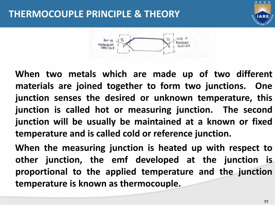
When two metals which are made up of two differentmaterials are joined together to form two junctions. Onejunction senses the desired or unknown temperature, thisjunction is called hot or measuring junction. The secondjunction will be usually be maintained at a known or fixedtemperature and is called cold or reference junction.
When the measuring junction is heated up with respect toother junction, the emf developed at the junction isproportional to the applied temperature and the junctiontemperature is known as thermocouple.
THERMOCOUPLE PRINCIPLE & THEORY
77
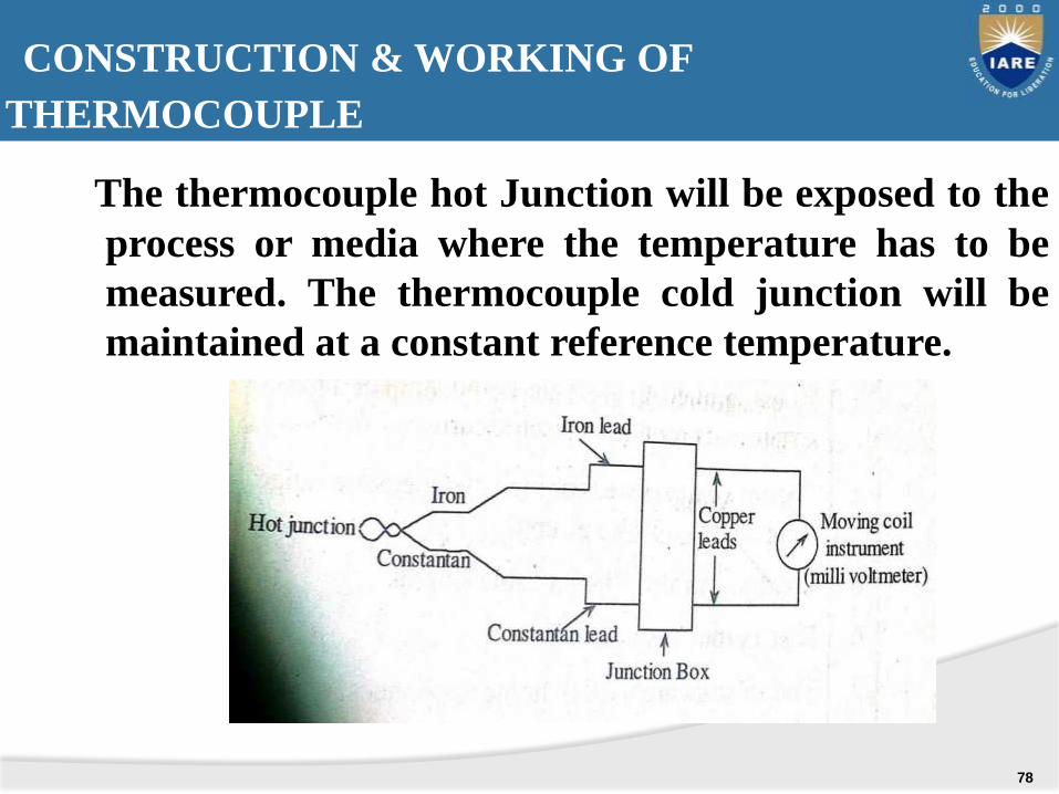
The thermocouple hot Junction will be exposed to the
process or media where the temperature has to be
measured. The thermocouple cold junction will be
maintained at a constant reference temperature.
CONSTRUCTION & WORKING OF
THERMOCOUPLE
78

.
COMMON METHODS FOR SEPARATING THERMOCOUPLE WIRES
79
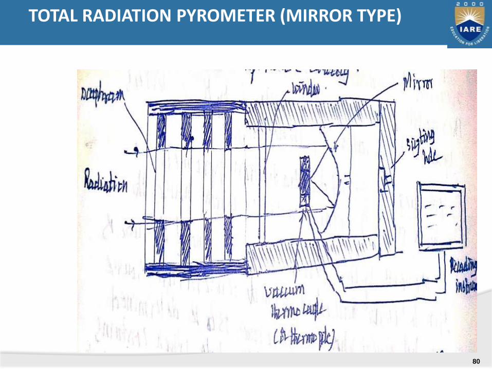
TOTAL RADIATION PYROMETER (MIRROR TYPE)
80
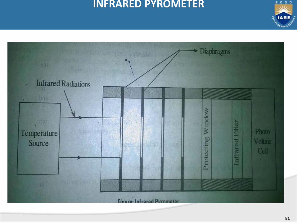
INFRARED PYROMETER
81

OPTICAL PYROMETER
82
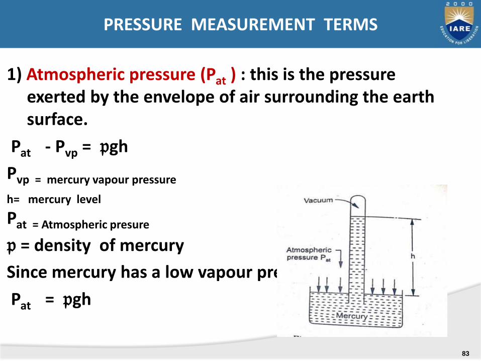
1) Atmospheric pressure (Pat ) : this is the pressure exerted by the envelope of air surrounding the earth surface.
Pat - Pvp = 𝔭gh
Pvp = mercury vapour pressure
h= mercury level
Pat = Atmospheric presure
𝔭 = density of mercury
Since mercury has a low vapour pressure Pvp = 0
Pat = 𝔭gh
PRESSURE MEASUREMENT TERMS
83
.
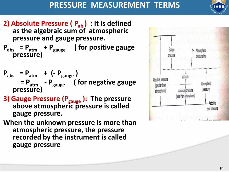
2) Absolute Pressure ( Pab ) : It is defined as the algebraic sum of atmospheric pressure and gauge pressure.
Pabs = Patm + Pgauge ( for positive gauge pressure)
Pabs = Patm + (- Pgauge ) = Patm - Pgauge ( for negative gauge
pressure)3) Gauge Pressure (Pgauge ): The pressure
above atmospheric pressure is called gauge pressure.
When the unknown pressure is more than atmospheric pressure, the pressure recorded by the instrument is called gauge pressure
PRESSURE MEASUREMENT TERMS
84
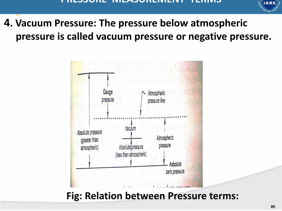
.4. Vacuum Pressure: The pressure below atmospheric
pressure is called vacuum pressure or negative pressure.
PRESSURE MEASUREMENT TERMS
Fig: Relation between Pressure terms:85
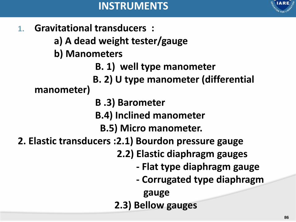
1. Gravitational transducers : a) A dead weight tester/gaugeb) Manometers
B. 1) well type manometerB. 2) U type manometer (differential
manometer)B .3) BarometerB.4) Inclined manometer
B.5) Micro manometer.2. Elastic transducers :2.1) Bourdon pressure gauge
2.2) Elastic diaphragm gauges- Flat type diaphragm gauge- Corrugated type diaphragm
gauge 2.3) Bellow gauges
INSTRUMENTS
86
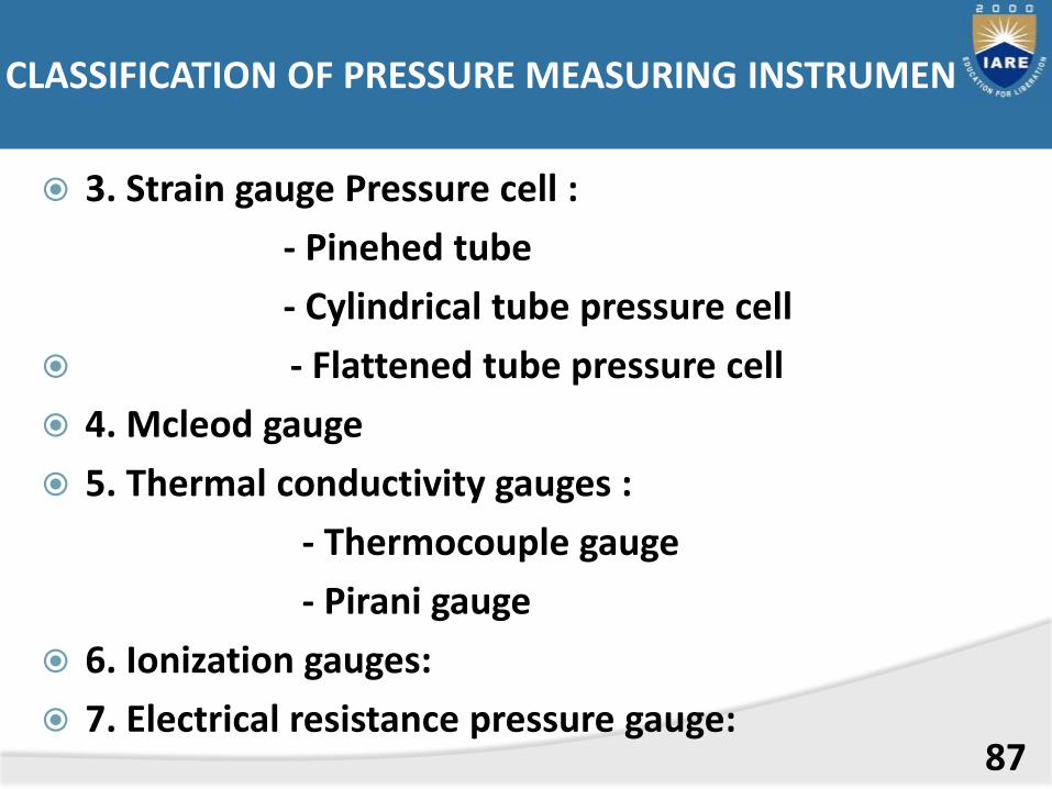
3. Strain gauge Pressure cell :
- Pinehed tube
- Cylindrical tube pressure cell
- Flattened tube pressure cell
4. Mcleod gauge
5. Thermal conductivity gauges :
- Thermocouple gauge
- Pirani gauge
6. Ionization gauges:
7. Electrical resistance pressure gauge:87
CLASSIFICATION OF PRESSURE MEASURING INSTRUMENTS

DEAD-WEIGHT TYPE TESTER OR GAUGE ( PISTON GAUGE)
88
B. 1) Well type manometer
B. 2) U type manometer (differential manometer)
B .3) Barometer
B.4) Inclined manometer
B.5) Micro manometer.
B) DIFFERENT TYPES OF MANOMETERS
89
-
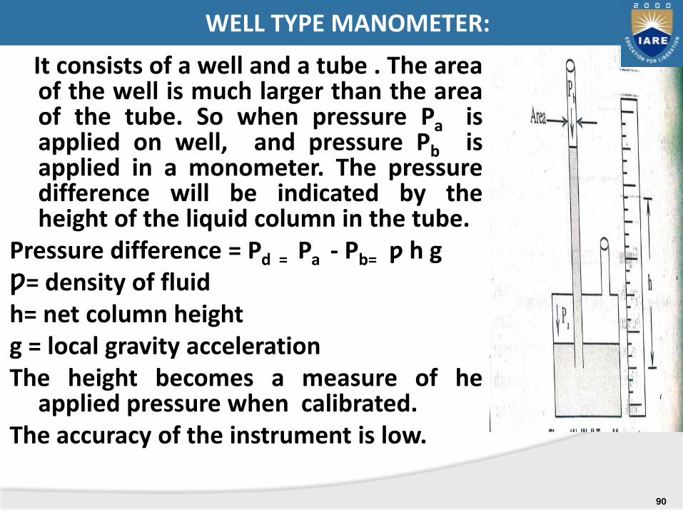
It consists of a well and a tube . The areaof the well is much larger than the areaof the tube. So when pressure Pa isapplied on well, and pressure Pb isapplied in a monometer. The pressuredifference will be indicated by theheight of the liquid column in the tube.
Pressure difference = Pd = Pa - Pb= ƿ h gǷ= density of fluidh= net column heightg = local gravity accelerationThe height becomes a measure of he
applied pressure when calibrated.The accuracy of the instrument is low.
WELL TYPE MANOMETER:
90
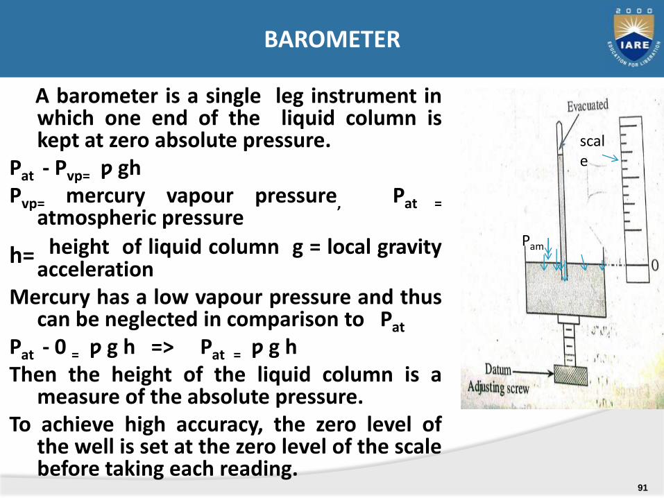
A barometer is a single leg instrument inwhich one end of the liquid column iskept at zero absolute pressure.
Pat - Pvp= ƿ ghPvp= mercury vapour pressure, Pat =
atmospheric pressure
h= height of liquid column g = local gravityacceleration
Mercury has a low vapour pressure and thuscan be neglected in comparison to Pat
Pat - 0 = ƿ g h => Pat = ƿ g hThen the height of the liquid column is a
measure of the absolute pressure.To achieve high accuracy, the zero level of
the well is set at the zero level of the scalebefore taking each reading.
scale
Pam
BAROMETER
91
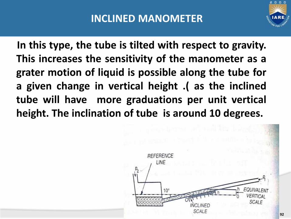
In this type, the tube is tilted with respect to gravity.This increases the sensitivity of the manometer as agrater motion of liquid is possible along the tube fora given change in vertical height .( as the inclinedtube will have more graduations per unit verticalheight. The inclination of tube is around 10 degrees.
92
INCLINED MANOMETER
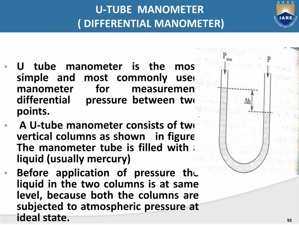
• U tube manometer is the mostsimple and most commonly usedmanometer for measurementdifferential pressure between twopoints.
• A U-tube manometer consists of twovertical columns as shown in figure.The manometer tube is filled with aliquid (usually mercury)
• Before application of pressure theliquid in the two columns is at samelevel, because both the columns aresubjected to atmospheric pressure atideal state.
U-TUBE MANOMETER( DIFFERENTIAL MANOMETER)
93
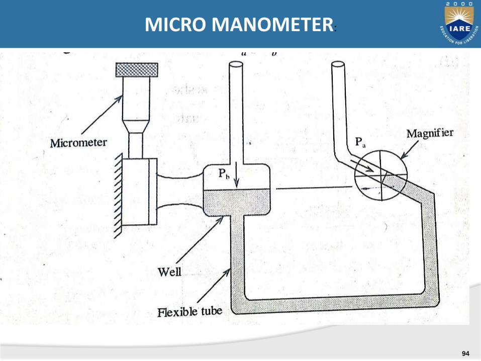
MICRO MANOMETER:
94
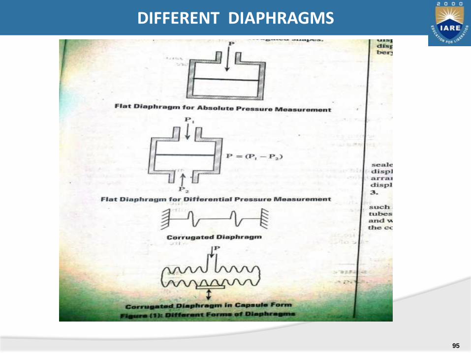
DIFFERENT DIAPHRAGMS
95
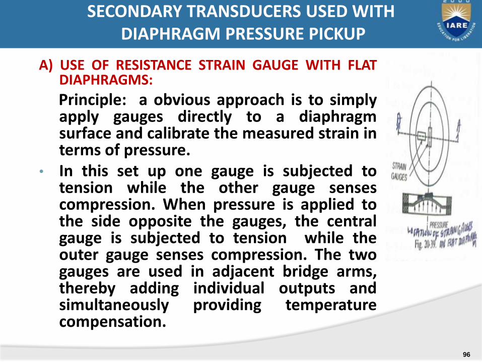
A) USE OF RESISTANCE STRAIN GAUGE WITH FLATDIAPHRAGMS:
Principle: a obvious approach is to simplyapply gauges directly to a diaphragmsurface and calibrate the measured strain interms of pressure.
• In this set up one gauge is subjected totension while the other gauge sensescompression. When pressure is applied tothe side opposite the gauges, the centralgauge is subjected to tension while theouter gauge senses compression. The twogauges are used in adjacent bridge arms,thereby adding individual outputs andsimultaneously providing temperaturecompensation.
SECONDARY TRANSDUCERS USED WITHDIAPHRAGM PRESSURE PICKUP
96

B) USE OF INDUCTIVE TYPE TRANSDUCER WITH FLAT DIAPHRAGMS:
• Variable inductance is used as aform of secondary transducer usedwith a diaphragm.
• .in inductive type of secondarytransducer the flexing of thediaphragm is utilized to change therelative induction of two coils placedin the magnetic field.
• The device consists of two E-shapedmagnetic pieces placed equallyaround a diaphragm. Two coils arewounded around these E-shapedpieces.
SECONDARY TRANSDUCERS/PICKUP USED WITHDIAPHRAGM PRESSURE .
97
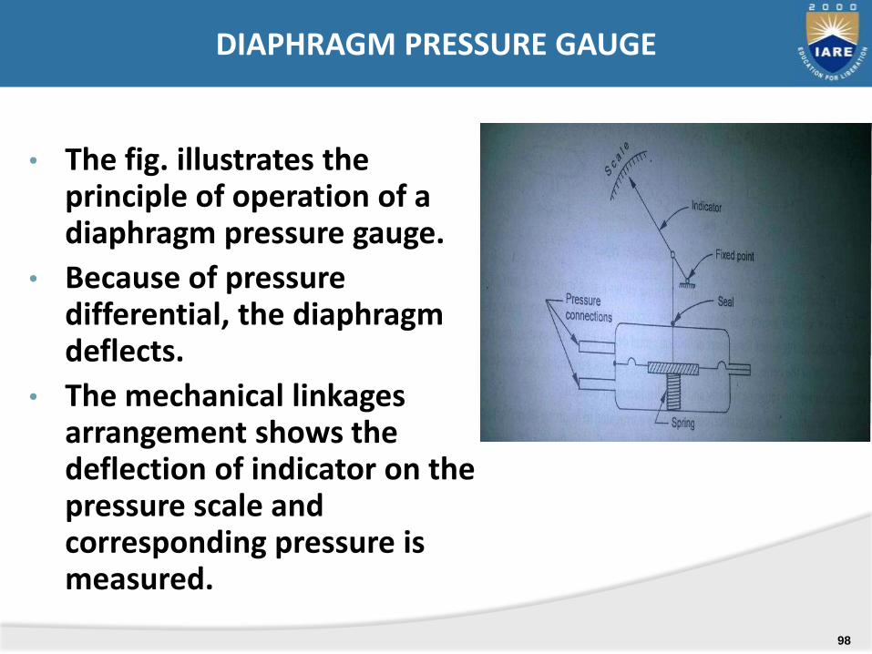
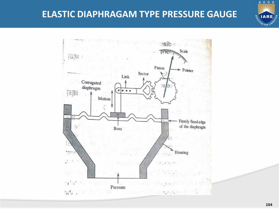
• The fig. illustrates the principle of operation of a diaphragm pressure gauge.
• Because of pressure differential, the diaphragm deflects.
• The mechanical linkages arrangement shows the deflection of indicator on the pressure scale and corresponding pressure is measured.
DIAPHRAGM PRESSURE GAUGE
98

• Bellows, the pressure measuring elementsare formed by the series combination ofcapsules. The working principle of bellow issame that of diaphragms; ie the applieddisplacement is converted intoproportionate mechanical displacement.
• The materials used to construct bellowsare brryllium copper, brass, monel,stainless steel and nickel.
• When ever the pressure to be measured isapplied to the sealed end of bellow, suffersdisplacement. The generated displacementcan be known by attaching a pointer scalearrangement to the sealed end bytransmitting the displacement to thesecondary transducer.
ii) PRESSURE MEASUREMENT WITH BELLOWS:
99
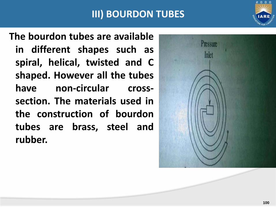
The bourdon tubes are availablein different shapes such asspiral, helical, twisted and Cshaped. However all the tubeshave non-circular cross-section. The materials used inthe construction of bourdontubes are brass, steel andrubber.
III) BOURDON TUBES
100
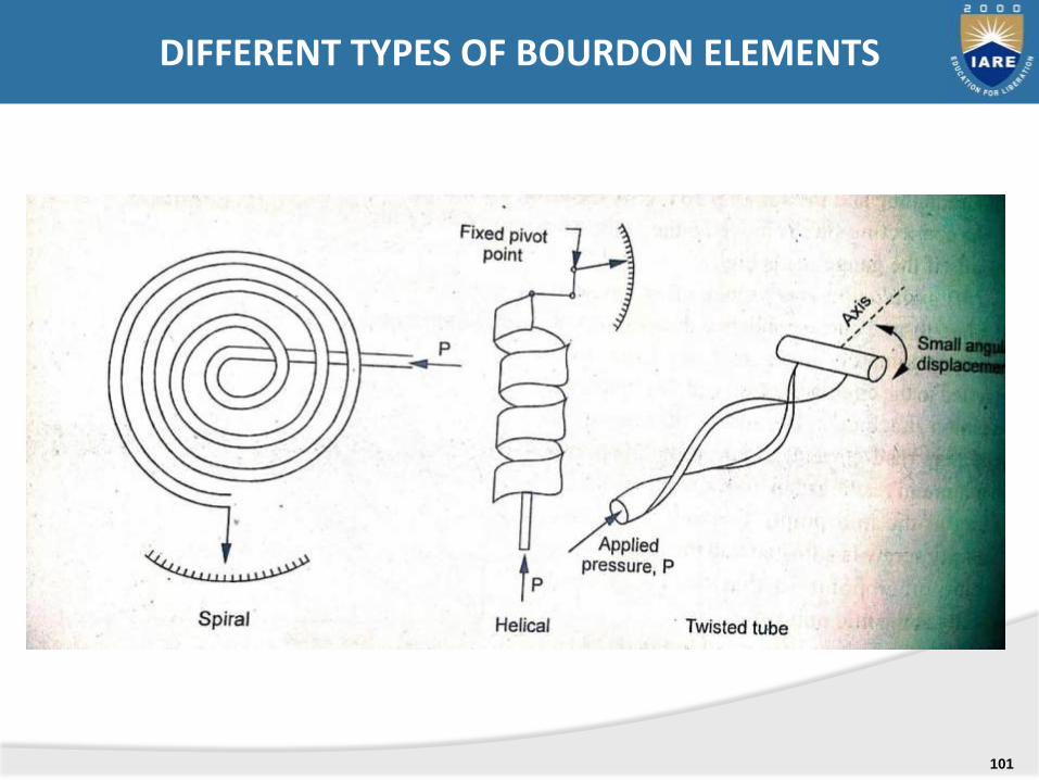
DIFFERENT TYPES OF BOURDON ELEMENTS
101
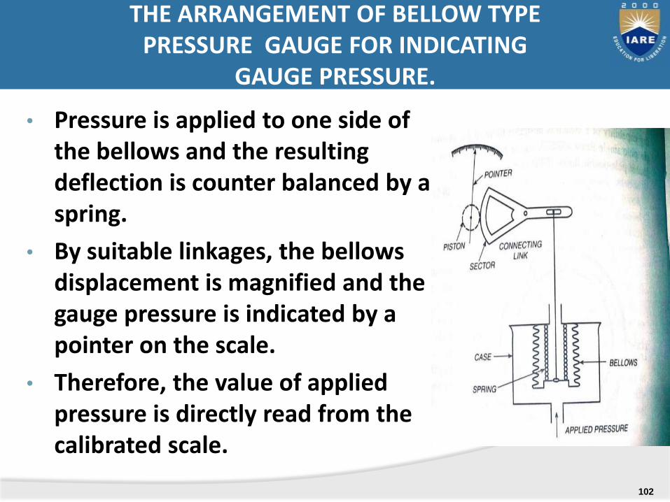
• Pressure is applied to one side of the bellows and the resulting deflection is counter balanced by a spring.
• By suitable linkages, the bellows displacement is magnified and the gauge pressure is indicated by a pointer on the scale.
• Therefore, the value of applied pressure is directly read from the calibrated scale.
THE ARRANGEMENT OF BELLOW TYPE PRESSURE GAUGE FOR INDICATING
GAUGE PRESSURE.
102
.
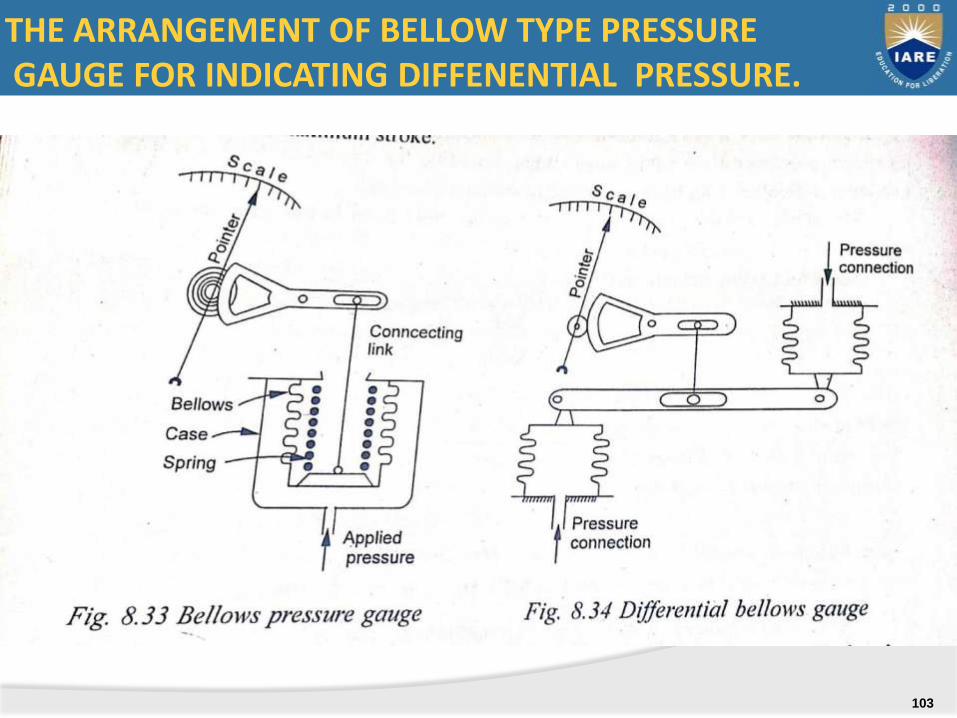
THE ARRANGEMENT OF BELLOW TYPE PRESSUREGAUGE FOR INDICATING DIFFENENTIAL PRESSURE.
103
ELASTIC DIAPHRAGAM TYPE PRESSURE GAUGE
104
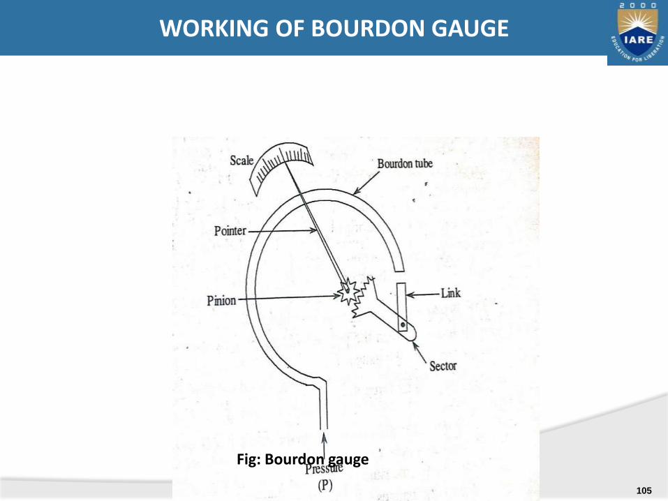
Fig: Bourdon gauge
WORKING OF BOURDON GAUGE
105
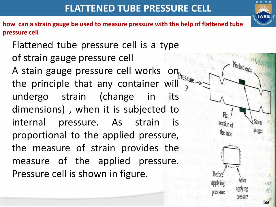
Flattened tube pressure cell is a typeof strain gauge pressure cellA stain gauge pressure cell works onthe principle that any container willundergo strain (change in itsdimensions) , when it is subjected tointernal pressure. As strain isproportional to the applied pressure,the measure of strain provides themeasure of the applied pressure.Pressure cell is shown in figure.
FLATTENED TUBE PRESSURE CELL
how can a strain gauge be used to measure pressure with the help of flattened tube pressure cell
106
A
B
FD
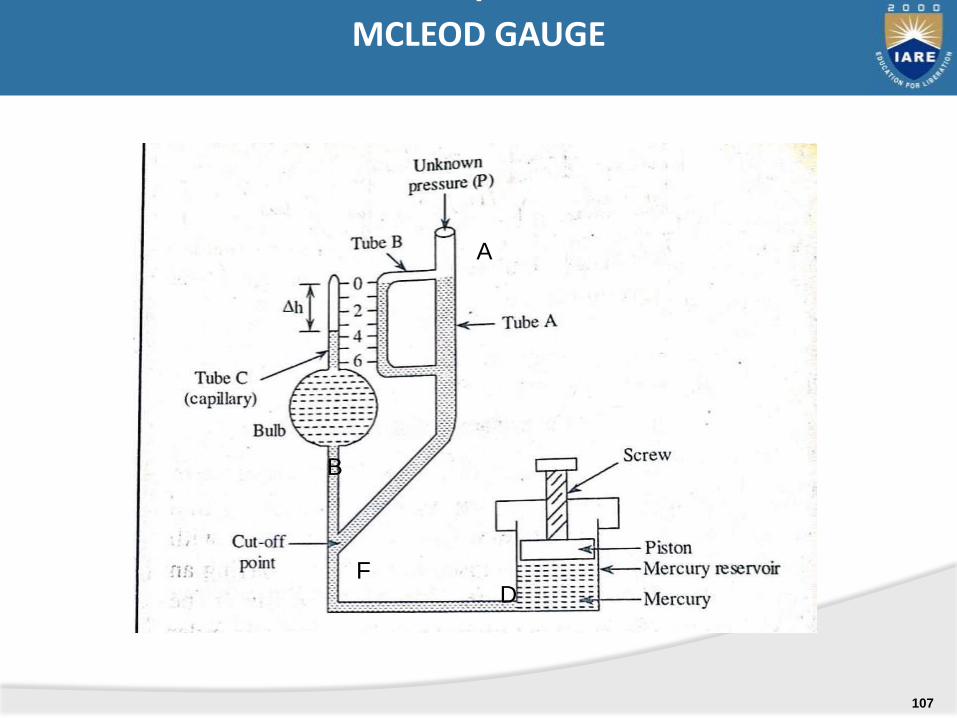
IMCLEOD GAUGE
107

IIA) THE PIRANI-TYPE THERMAL CONDUCTIVITYGAUGE FOR LOW PRESSURE MEASUREMENT
108
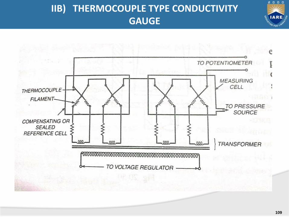
IIB) THERMOCOUPLE TYPE CONDUCTIVITY GAUGE
109
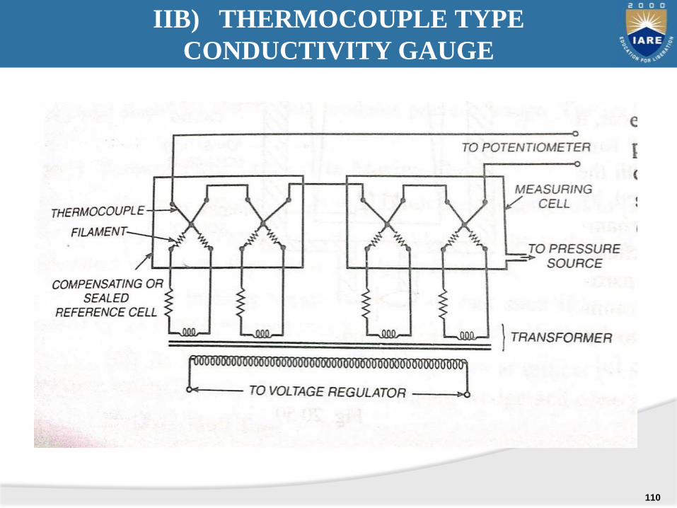
IIB) THERMOCOUPLE TYPE
CONDUCTIVITY GAUGE
110
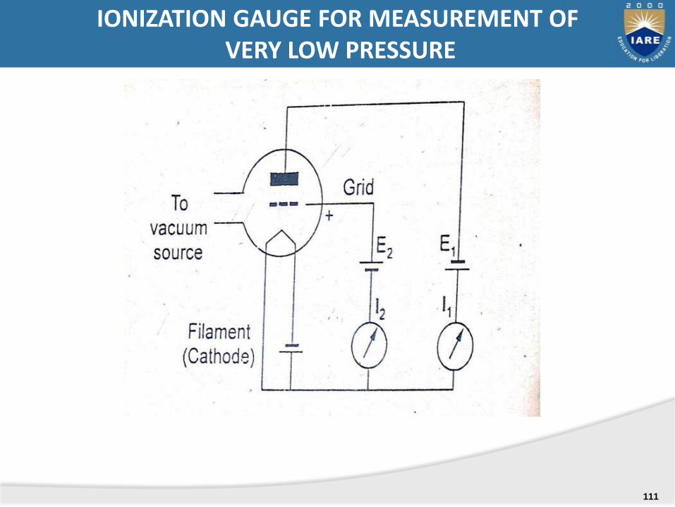
IONIZATION GAUGE FOR MEASUREMENT OFVERY LOW PRESSURE
111
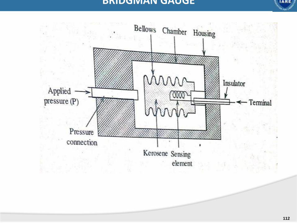
BRIDGMAN GAUGE
112

INCLINED TUBE MANOMETER
h
1
h2
P1P2
DERIVE AN EQUATION FOR DIFFERENTIAL PRESSUREBASED ON THE MOVEMENT OF LIQUID IN THE
INCLINED COLUMN ONLY
113
SYLLABUS:
DIRECT METHODS:
INDIRECT METHODS:
Capacitive , ultrasonic, magnetic,
bubbler level, Cryogenic fuel level indicator
UNIT-IIIA MEASUREMENT OF LEVEL
114
In the modern manufacturing industries whichuses many solvents, chemicals, steam and otherliquids
Power plants use vast amount of water , theaccurate measurement of liquid is very essential.
INTRODUCTION TO LEVEL
115
A) DIRECT METHODS: which uses the varying level ofthe liquid as a means of obtaining the measurement.The response of the device
indicates the changes in liquid level directly.A1) sight glass level gaugeA2) Bob and tape methodA3) hook type level gaugeA4) Float level indicatorA5) float and shaft liquid level gaugeA6) Displacer type liquid level measuring instrument
- Torque tube displacer- Spring balance displacer
METHODS OF MEASURING LEVEL
116
B) INDIRECT METHODS
In indirect methods of level measurement methods, usesa variable (resistance, capacitance, inductance,buoyancy force, hydrostatic pressure ) that changeswith the liquid level to actuate measuring mechanism.
Thus the change occurred in these parameters gives themeasure of liquid level.
B1) Capacitive type level indicator.B2) Float operated potentiometer(Electrical resistanceB3) Ultrasonic level measurement instrument.B4) Bubbler (Purge) type level indicatorB5) Magnetic type level indicatorB6) Radioactive method for level measurement.B7) cryogenic fuel level indicator.
METHODS OF MEASURING LEVEL … contd.
117
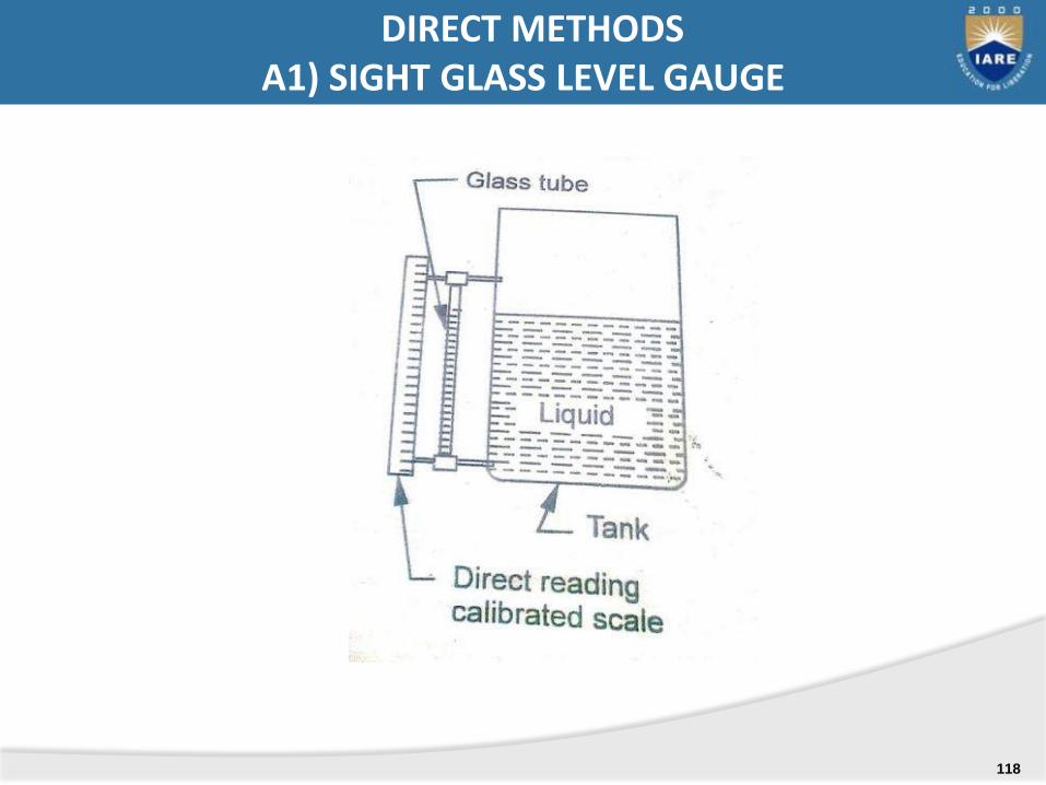
DIRECT METHODSA1) SIGHT GLASS LEVEL GAUGE
118
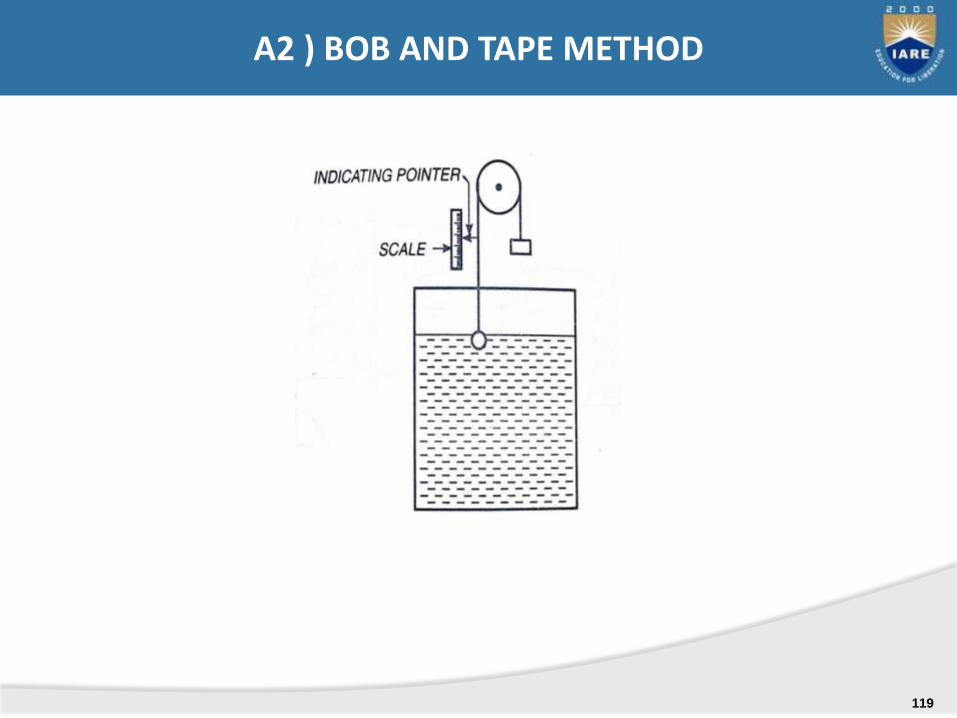
A2 ) BOB AND TAPE METHOD
119
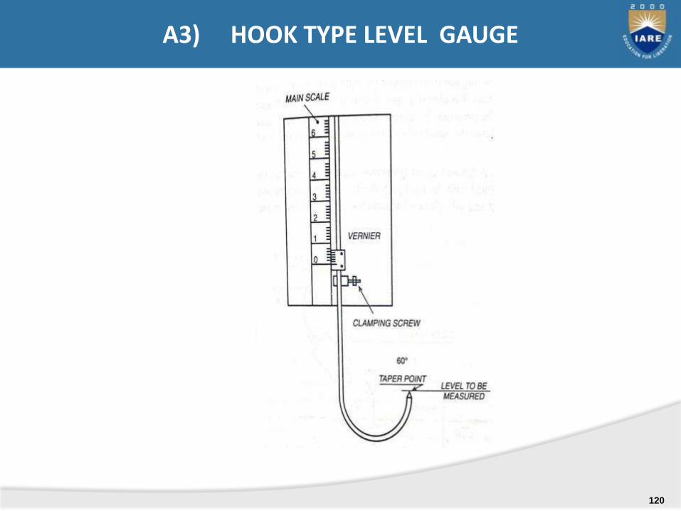
A3) HOOK TYPE LEVEL GAUGE
120
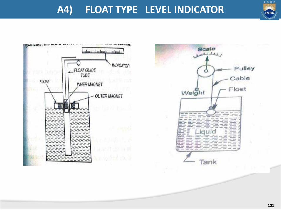
A4) FLOAT TYPE LEVEL INDICATOR
121
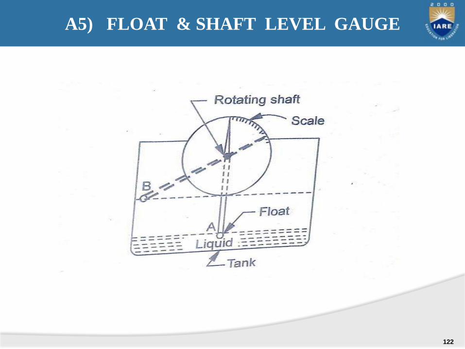
A5) FLOAT & SHAFT LEVEL GAUGE
122
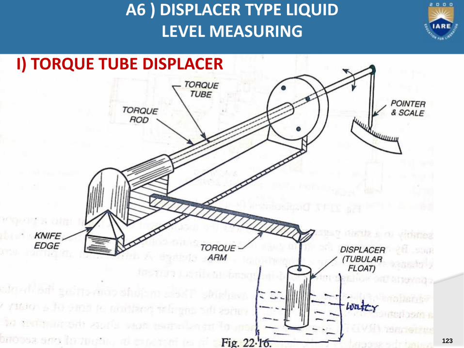
A6 ) DISPLACER TYPE LIQUID LEVEL MEASURING
I) TORQUE TUBE DISPLACER
123
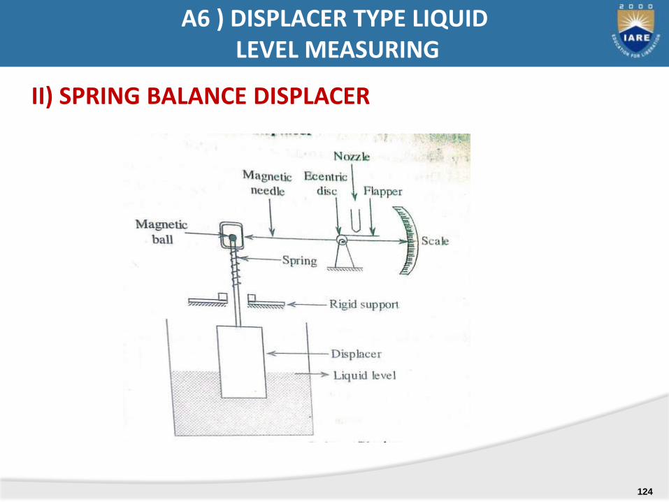
II) SPRING BALANCE DISPLACER
A6 ) DISPLACER TYPE LIQUIDLEVEL MEASURING
124
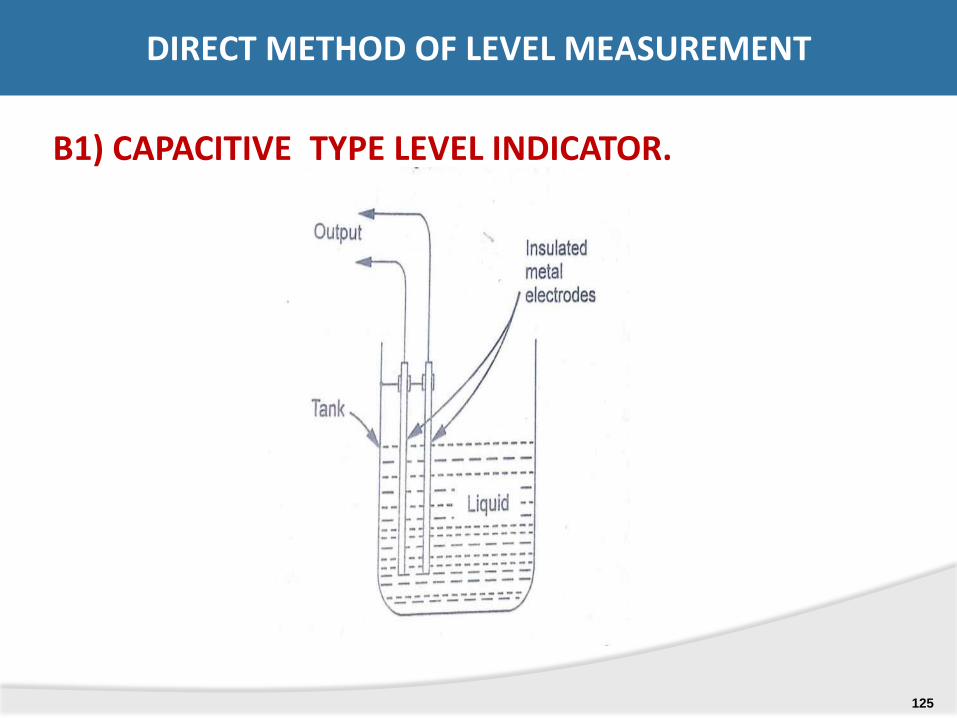
B1) CAPACITIVE TYPE LEVEL INDICATOR.
DIRECT METHOD OF LEVEL MEASUREMENT
125
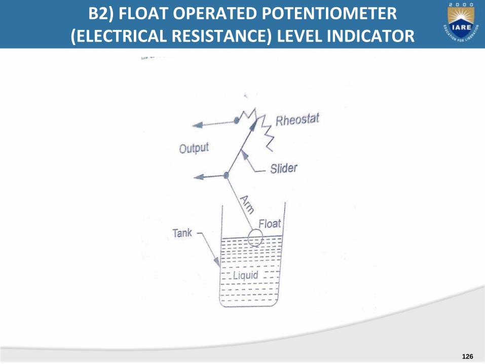
B2) FLOAT OPERATED POTENTIOMETER(ELECTRICAL RESISTANCE) LEVEL INDICATOR
126

B3) ULTRASONIC LEVEL MEASUREMENT INSTRUMENT
127

B4) BUBBLER (PURGE) TYPE LEVEL INDICATOR
128
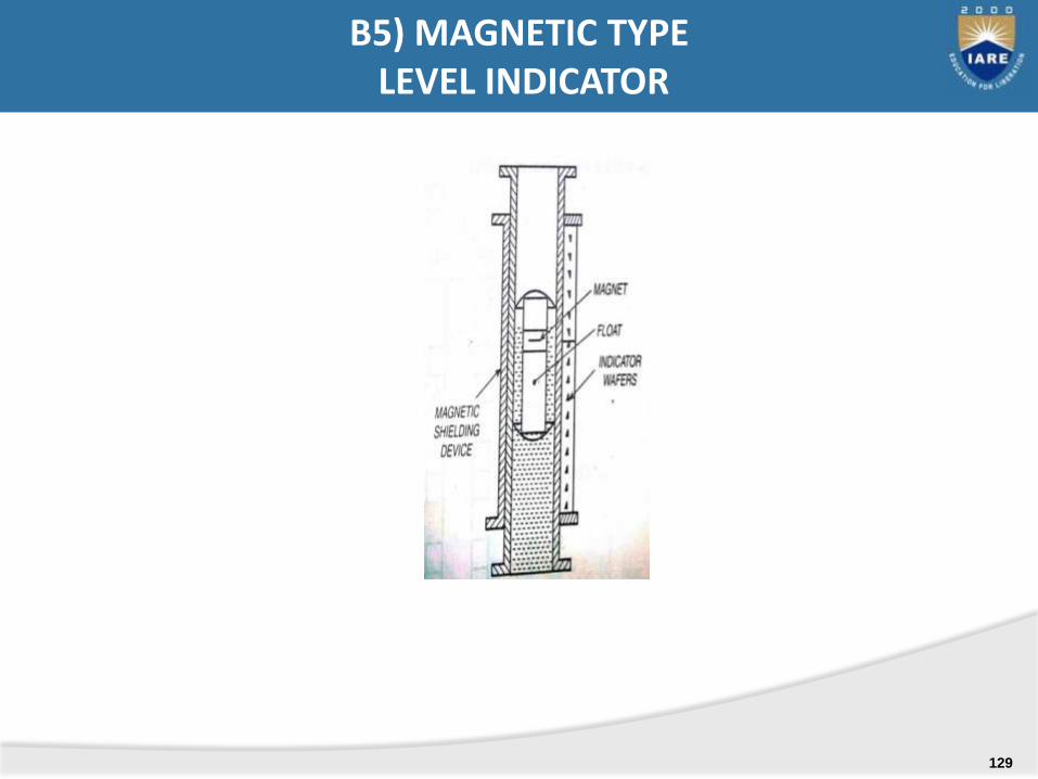
B5) MAGNETIC TYPELEVEL INDICATOR
129
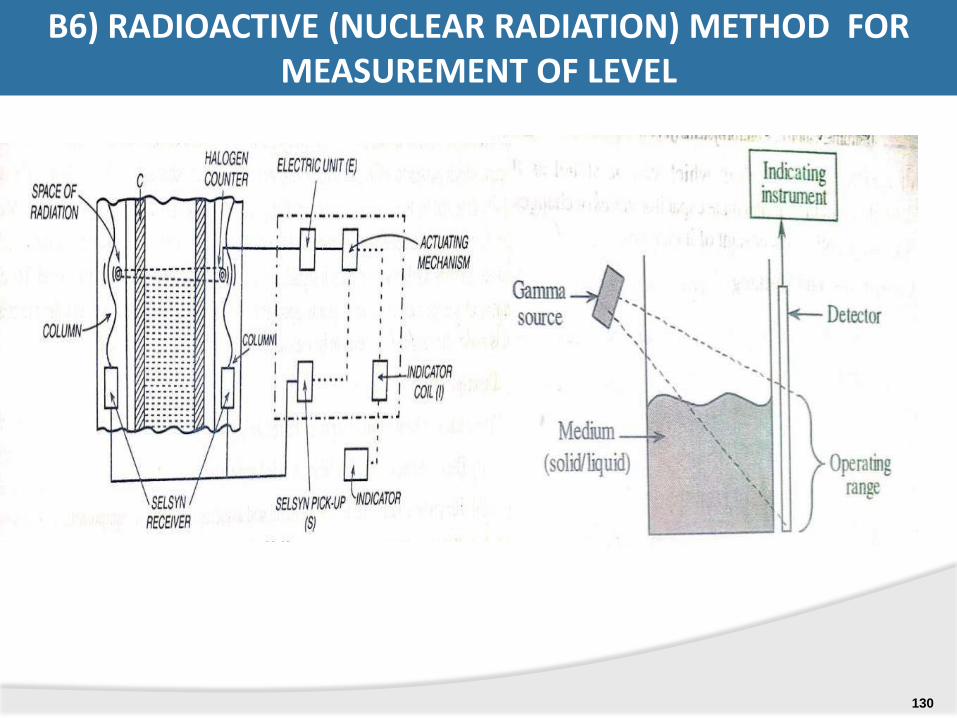
B6) RADIOACTIVE (NUCLEAR RADIATION) METHOD FOR MEASUREMENT OF LEVEL
130
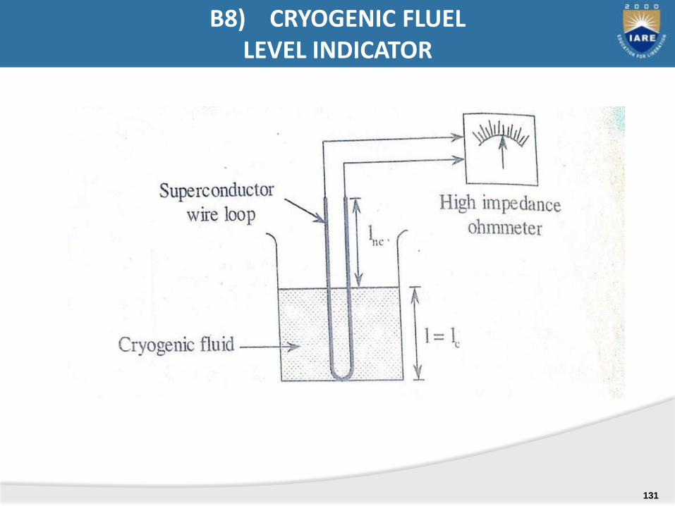
B8) CRYOGENIC FLUEL LEVEL INDICATOR
131
Syllabus:
Rotameter
Magnetic flow meter
Ultrasonic flow meter
Turbine flow meter
Hot-wire anemometer
Laser Doppler Anemometer (LDA)
MEASUREMENT OF FLOW
132
1) Rotameter (Variable area flow meter)
2) Magnetic flow meter
3) Turbine flow meter
4) Hot wire anemometer ( Thermal method_
5) Ultrasonic flow meter
6) Laser Doppler Anemometer (LDA)
FLOW MEASURING INSTRUMENTS
133
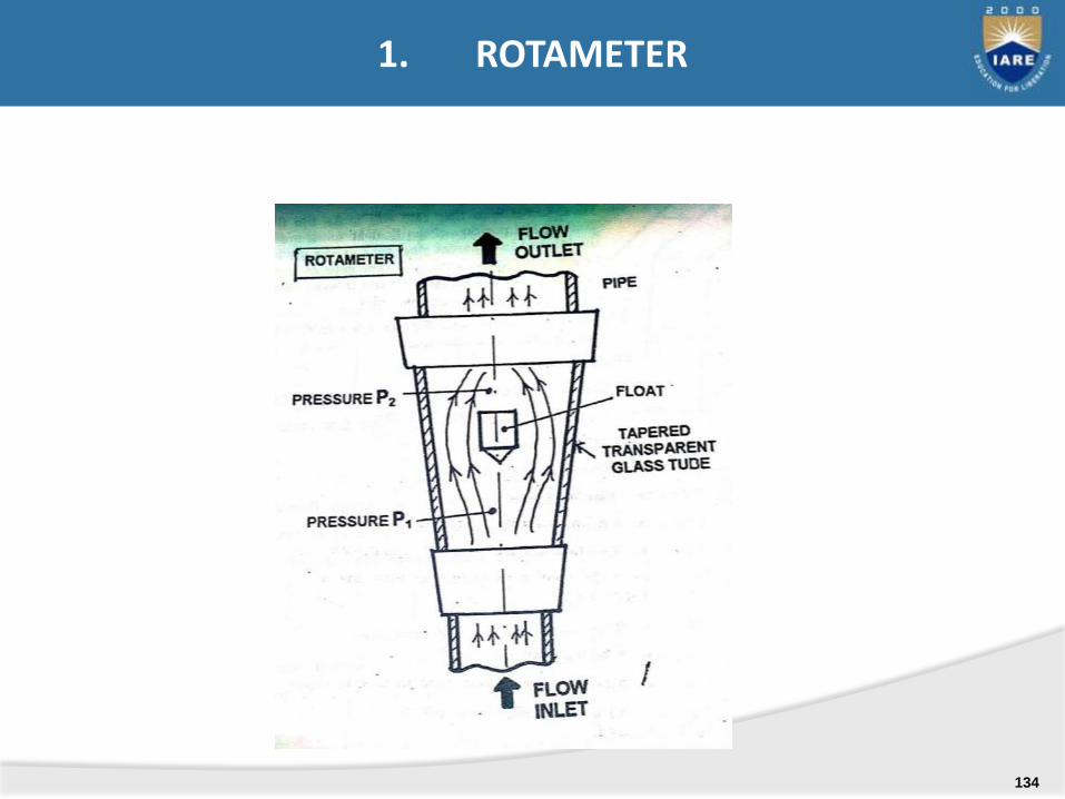
1. ROTAMETER
134

2. MAGNETIC FLOW METER
135
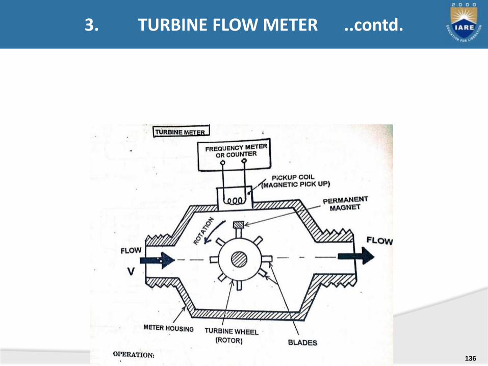
3. TURBINE FLOW METER ..contd.
136
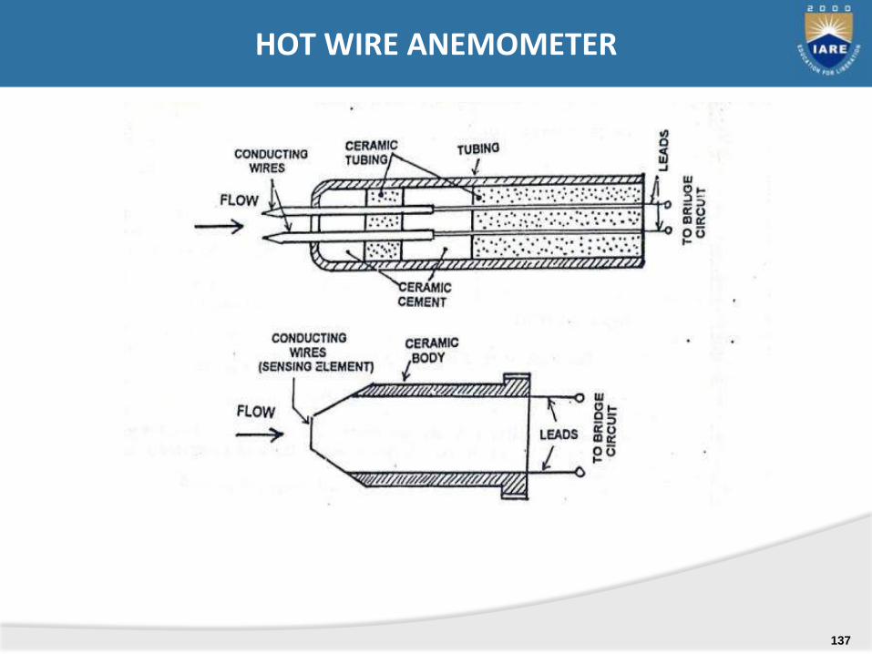
HOT WIRE ANEMOMETER
137
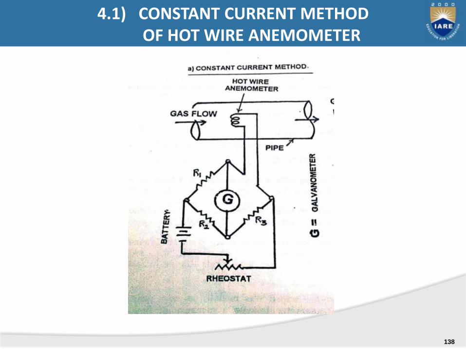
4.1) CONSTANT CURRENT METHOD OF HOT WIRE ANEMOMETER
138
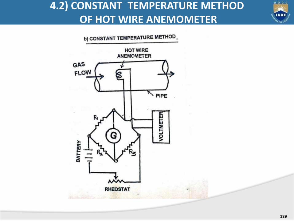
4.2) CONSTANT TEMPERATURE METHOD OF HOT WIRE ANEMOMETER
139
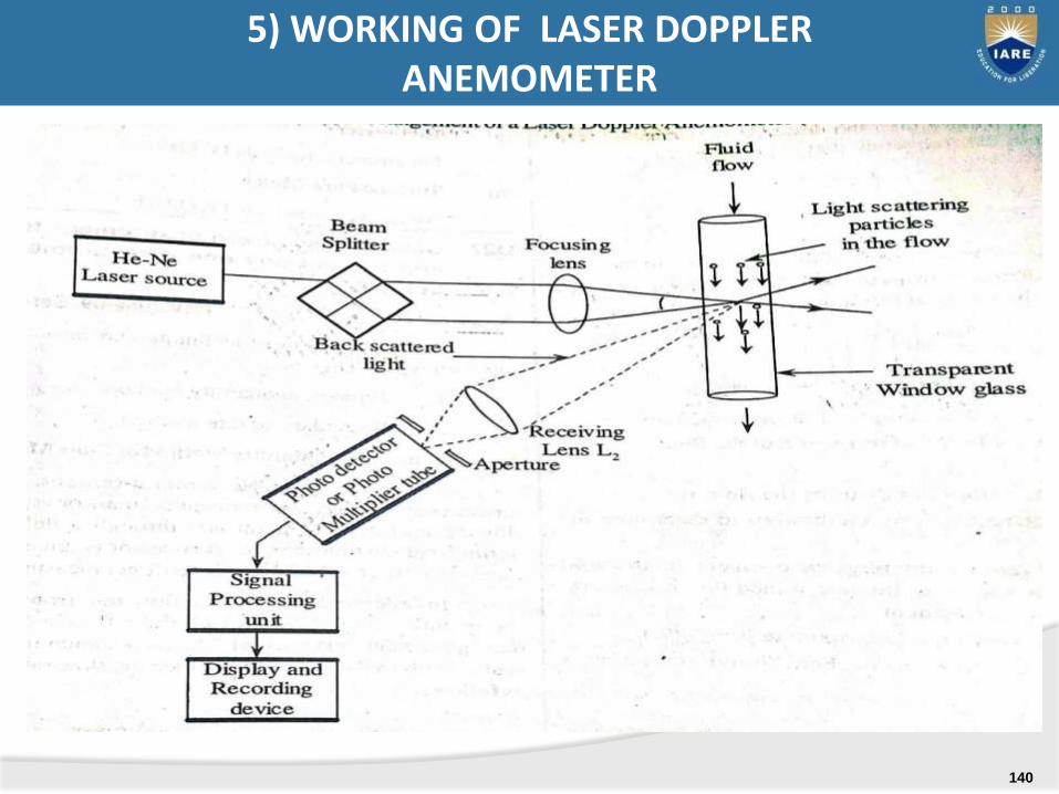
5) WORKING OF LASER DOPPLER ANEMOMETER
140
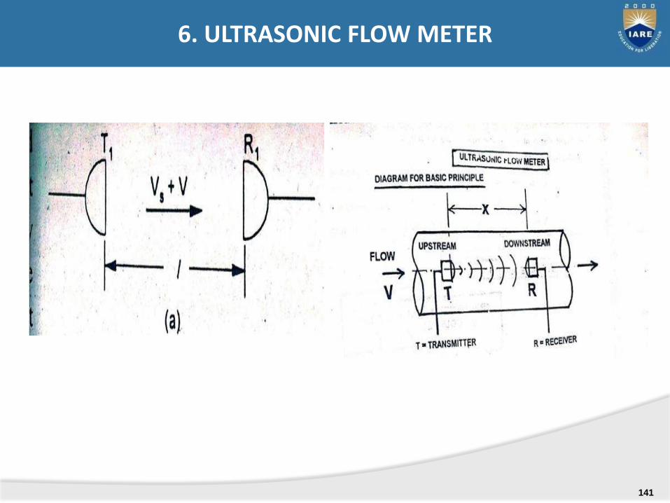
6. ULTRASONIC FLOW METER
141

1. TRAVEL TIME DIFFERENCE METHOD
6) ULTRASONIC FLOW METER
142
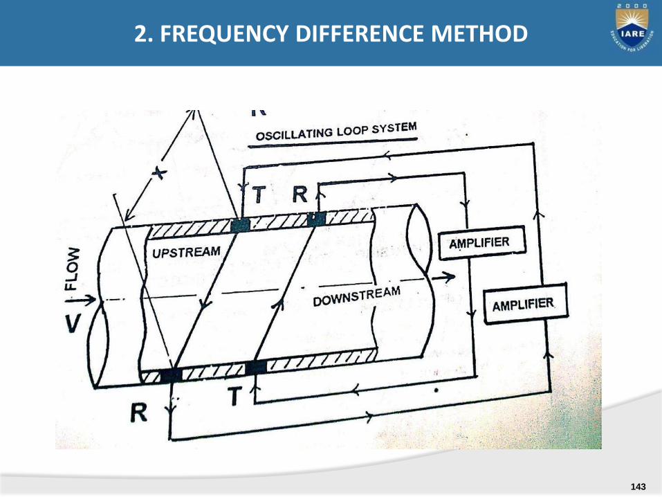
2. FREQUENCY DIFFERENCE METHOD
143
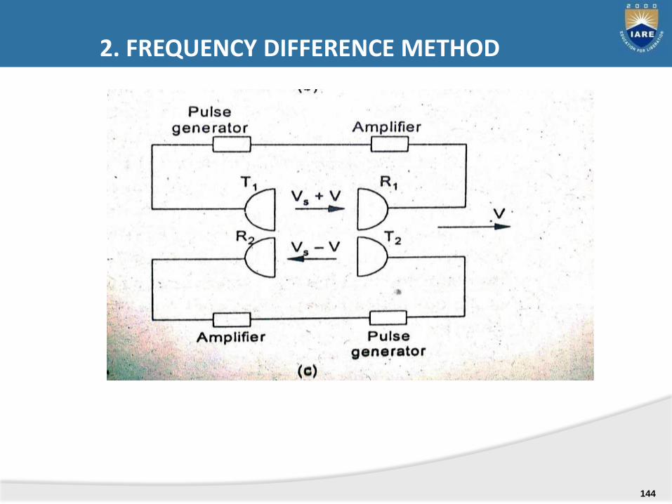
2. FREQUENCY DIFFERENCE METHOD
144

.
END OF MID-1 SYLLABUS
145
In this we study
Mechanical Tachometers
Electrical tachometers –
Stroboscope,
Noncontact type of tachometer
MEASUREMENT OF SPEED:
146
.
TACHOMETER: An instrument used to measure angular velocity of shaft by registering, the number of rotations during the period of contact, or by indicating directly the number of rotations per minute.
TACHOMETER:
147
1. Hand speed indicator
i. revolution counter & timer
ii. Tachoscope tachometer
iii. Hand speed indicator
2. Centrifugal force tachometer
3. Vibrating read tachometer
4. slipping clutch tachometer
MECHANICAL TACHOMETRS
148
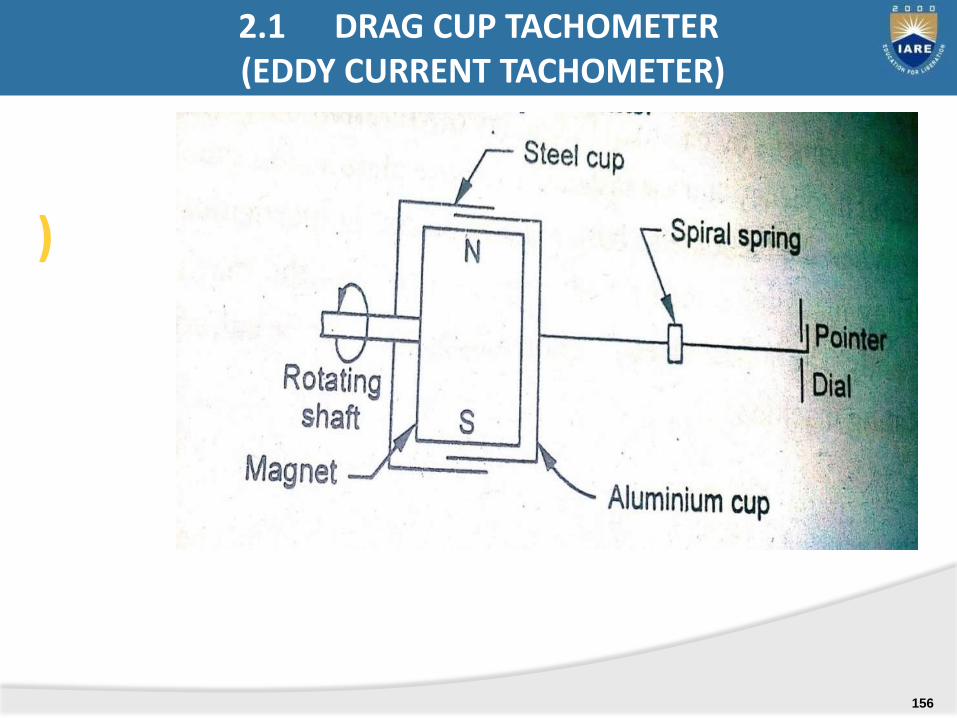
1 Drag cup tachometer(eddy current)
2 Tacho generators
i. DC tachometer generator
ii. Ac tachometer generator
3. Commutated capacitor tachometer
4. Contactless tachometer (non-contact type)
i. Inductive pickup tachometer
ii. capacitive type pickup tachometer
iii. Photo electric tachometer
iv. Stroboscope
ELECTRICAL TACHOMETERS
149
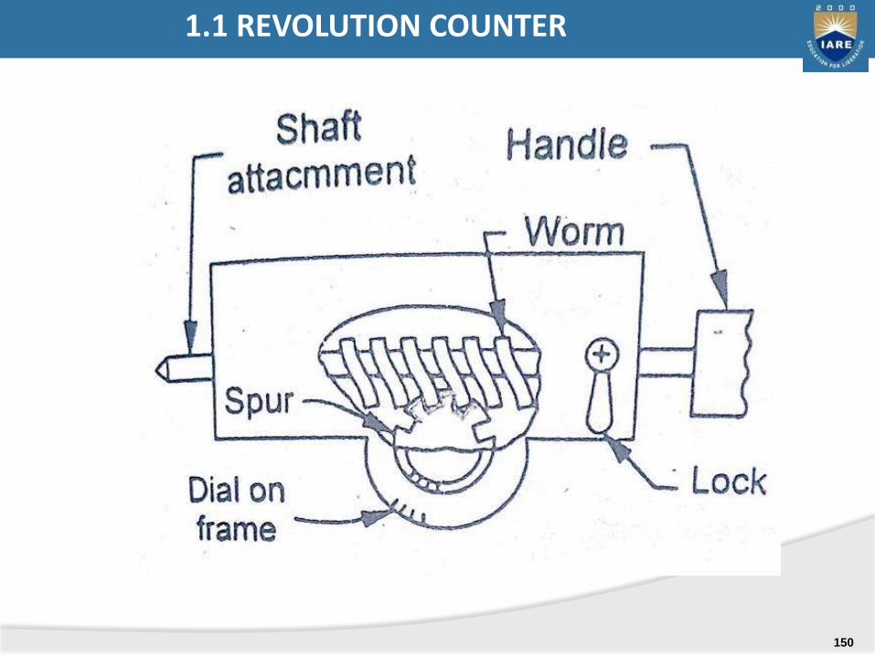
1.1 REVOLUTION COUNTER
150
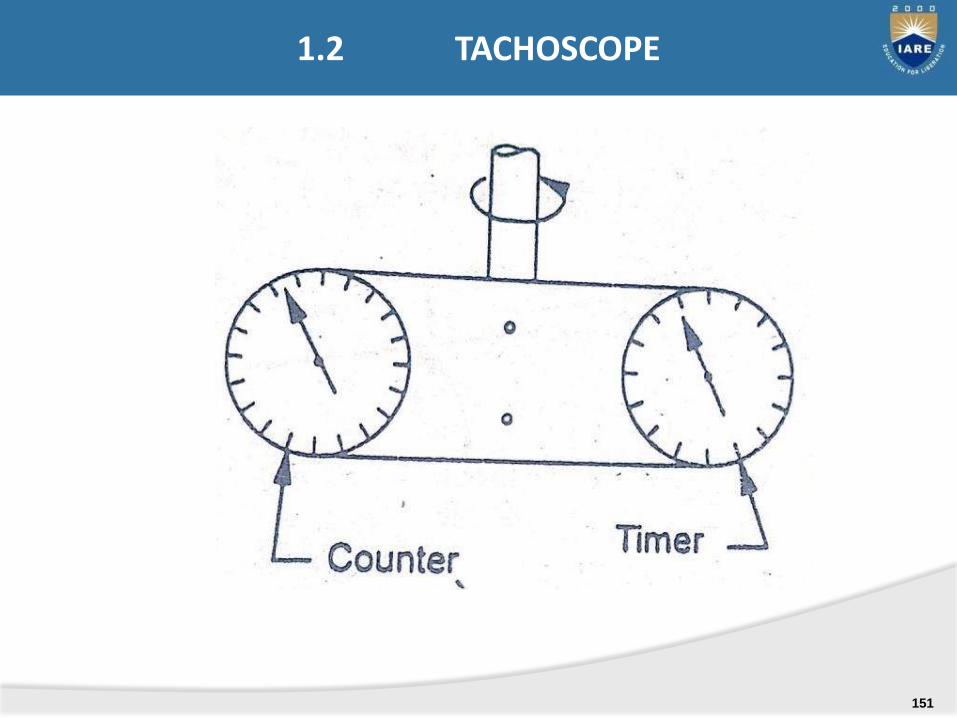
1.2 TACHOSCOPE
151
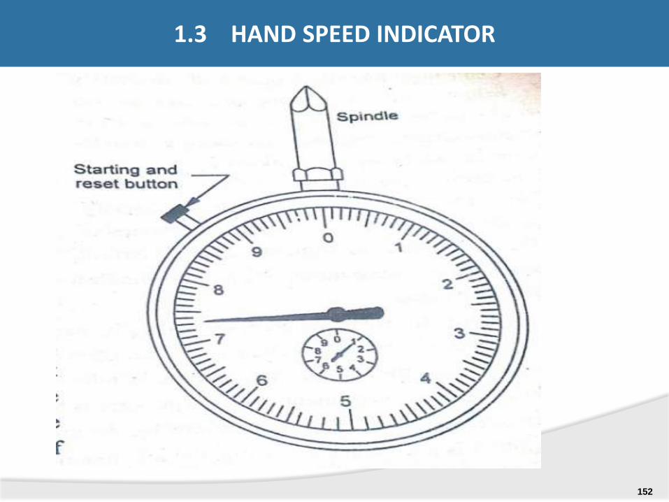
1.3 HAND SPEED INDICATOR
152
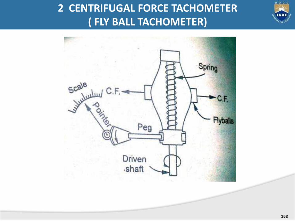
2 CENTRIFUGAL FORCE TACHOMETER ( FLY BALL TACHOMETER)
153
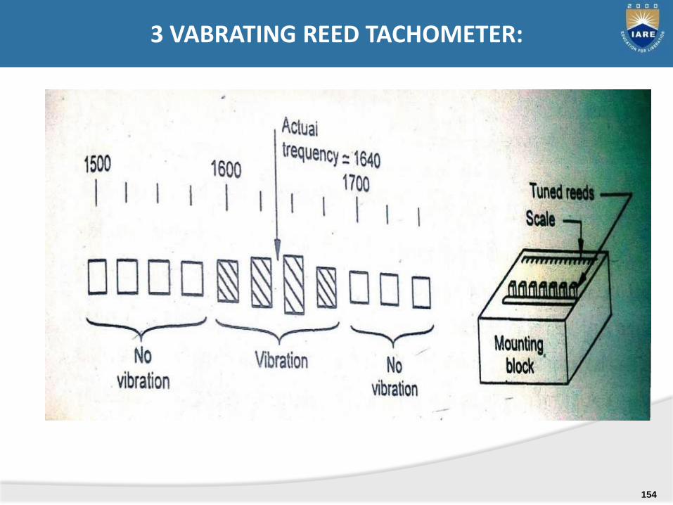
3 VABRATING REED TACHOMETER:
154

4. SLIPPING CLUTCH TACHOMETER
155
)
2.1 DRAG CUP TACHOMETER (EDDY CURRENT TACHOMETER)
156
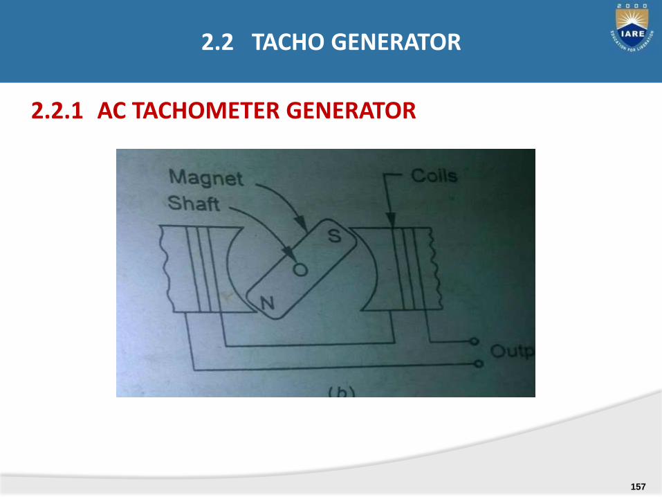
2.2.1 AC TACHOMETER GENERATOR
2.2 TACHO GENERATOR
157
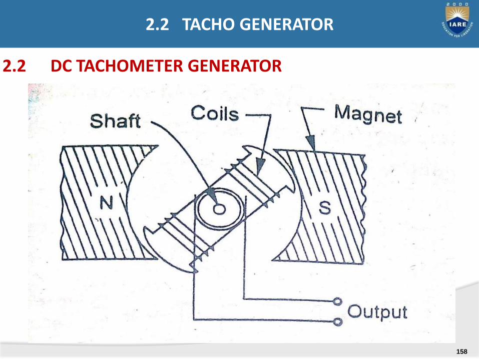
2.2 DC TACHOMETER GENERATOR
2.2 TACHO GENERATOR
158
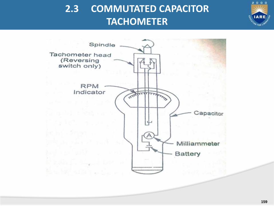
2.3 COMMUTATED CAPACITOR TACHOMETER
159
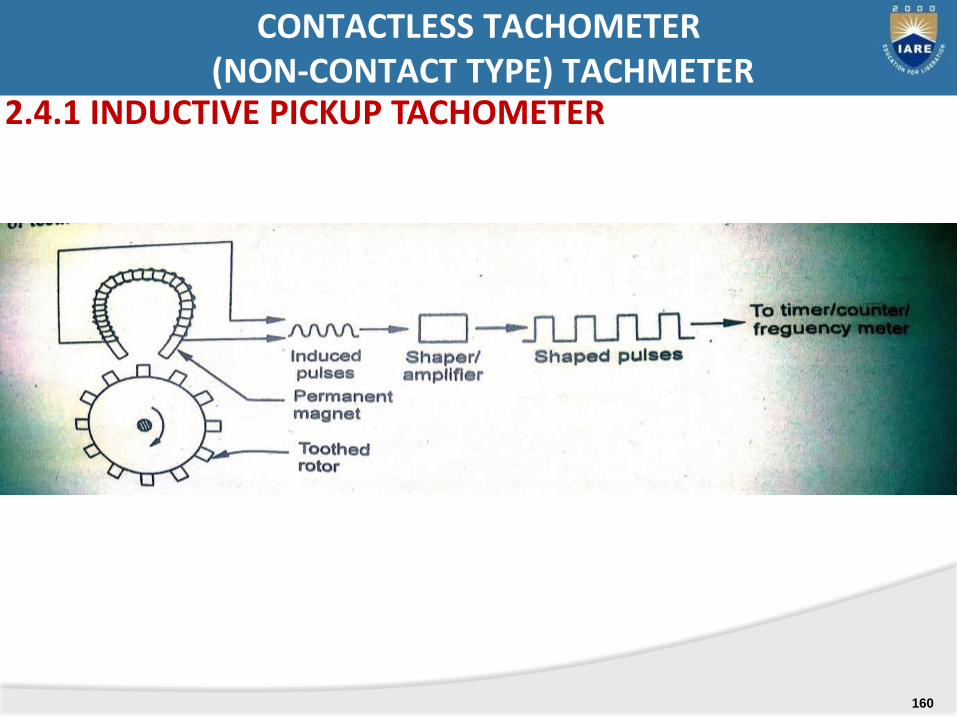
CONTACTLESS TACHOMETER(NON-CONTACT TYPE) TACHMETER
2.4.1 INDUCTIVE PICKUP TACHOMETER
160
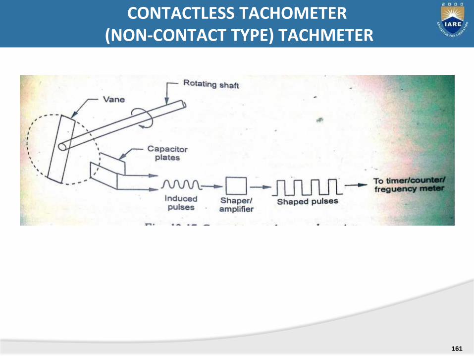
CONTACTLESS TACHOMETER(NON-CONTACT TYPE) TACHMETER
161
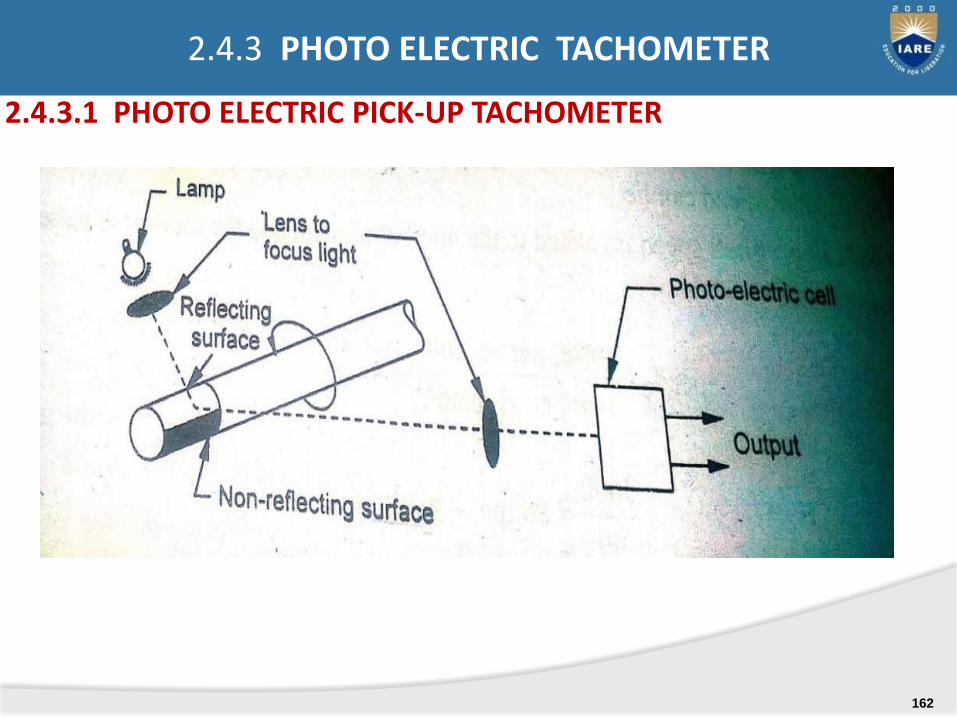
2.4.3.1 PHOTO ELECTRIC PICK-UP TACHOMETER
2.4.3 PHOTO ELECTRIC TACHOMETER
162
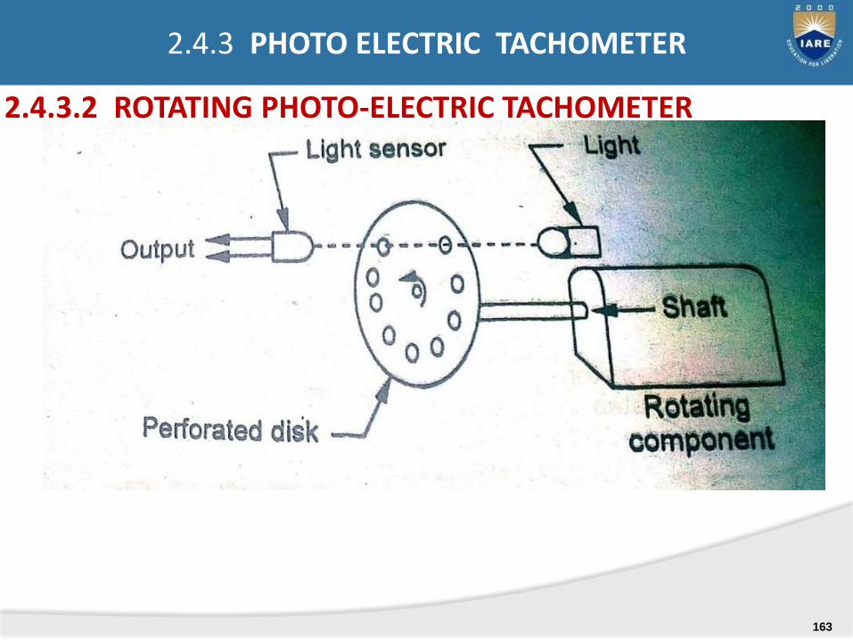
2.4.3.2 ROTATING PHOTO-ELECTRIC TACHOMETER
2.4.3 PHOTO ELECTRIC TACHOMETER
163
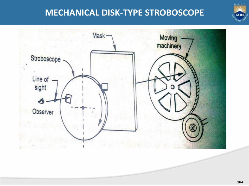
MECHANICAL DISK-TYPE STROBOSCOPE
164
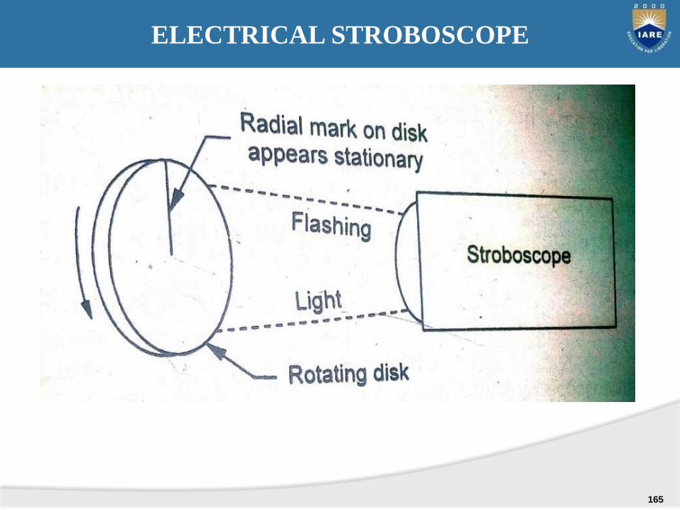
ELECTRICAL STROBOSCOPE
165

Vibration: vibration refers to the repeated cyclic oscillations of a system. The oscillatory motions may be simple harmonic (sinsusoidal) or complex (non-sinusoidal).
vibration: if the displacement –time variation is of a generally continuous form with some degree of repetitive nature, it is thought of being a vibration.
VIBRATION
166
DISADVANTAGES OF VIBRATION
temperature. For example a 100 c increase intemperature of a ball bearing is said to Abnormalvibrations in machine cause accelerated wear. Even asmall in-significant increase in the level of vibrationcauses a sharp increase in bearing wear as result ofraising reduce the service life of bearing by half.
Vibrations in peripheral machine parts can causepermanent damage attributable to fatigue in weldsand bolted joints.
Increased vibrations levels in a machine will lead tooperational difficulties sooner
167

COMMON CAUSES OF VIBRATION
Imbalance of machine
Resonances : occurs when the speed of machineryequals to its natural frequency of vibration. This canbe eliminated by decreasing or increasing the mass orthe spring constant.
Misalignment.
Mechanical & electrical asymmetry
Use of wrong ball bearing
168
FOR LINEAR MOTION:
Displacement = S= f(t)
Velocity = V = ds/dt
Acceleration = a= dv/dt = d2t/ dt2
linear jerk = da/dt
FOR ANGULAR MOTION:
Angular displacement = Θ = g(t)
Angular velocity = Ω = d Θ/dt
Angular acceleration = α = dΩ/dt = d2t/dt2
Angular Jerk = dα/dt
DEFINING RELATIONSHIPS
169
Vibrometer: A vibrometer is a device used for measurement of vibrations.
Accelerometer: A accelerometer is a device used for measurement of acceleration.
VIBROMETER AND ACCELEROMETER
170
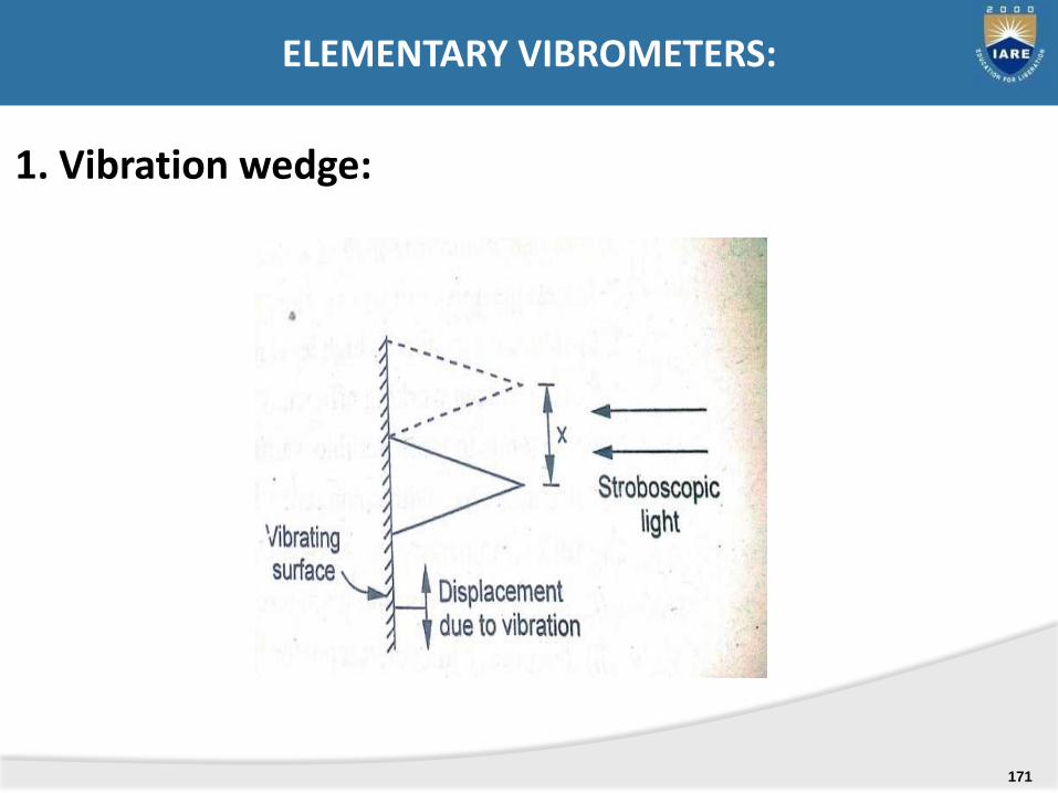
1. Vibration wedge:
ELEMENTARY VIBROMETERS:
171
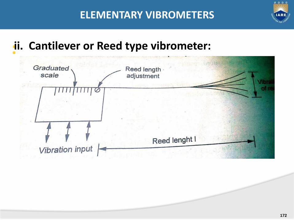
:ii. Cantilever or Reed type vibrometer:
ELEMENTARY VIBROMETERS
172
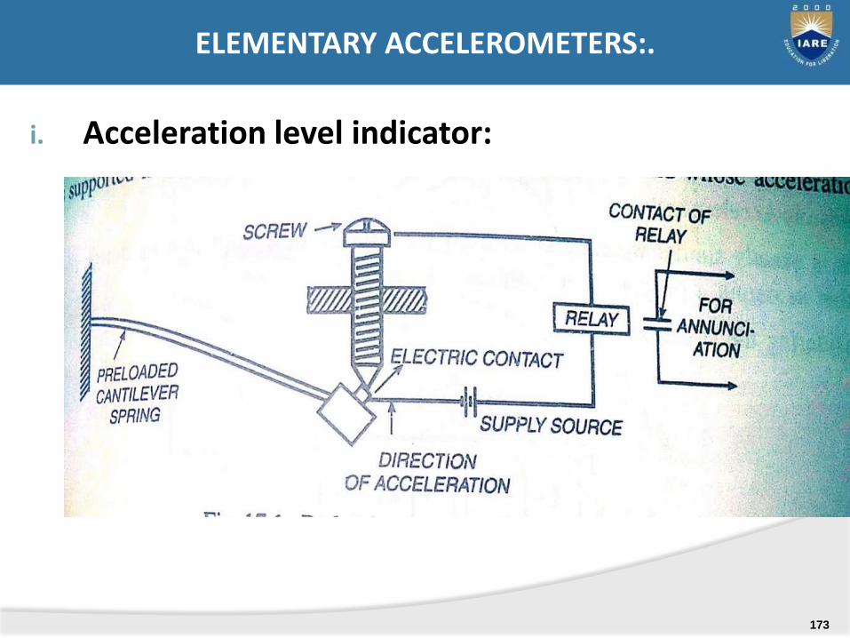
i. Acceleration level indicator:
ELEMENTARY ACCELEROMETERS:.
173
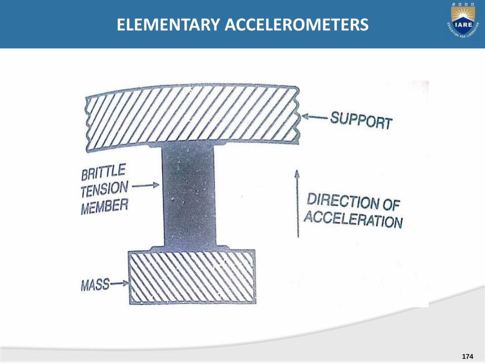
ELEMENTARY ACCELEROMETERS
174
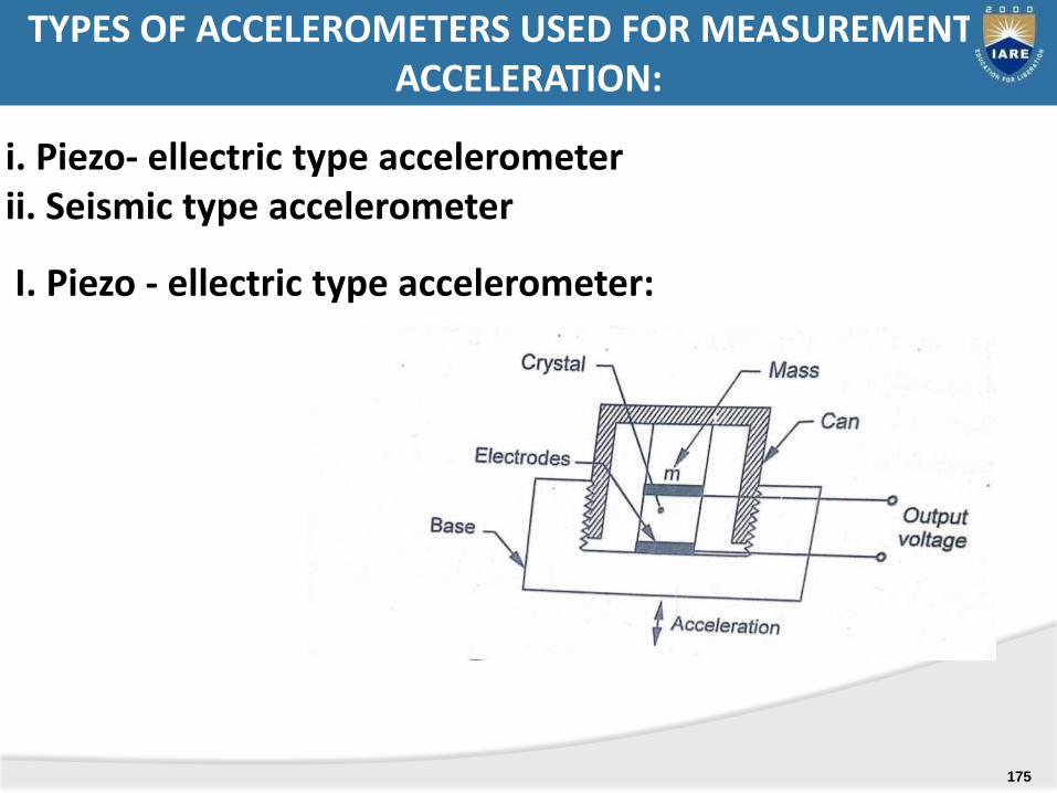
i. Piezo- ellectric type accelerometerii. Seismic type accelerometer
I. Piezo - ellectric type accelerometer:
TYPES OF ACCELEROMETERS USED FOR MEASUREMENT OF ACCELERATION:
175
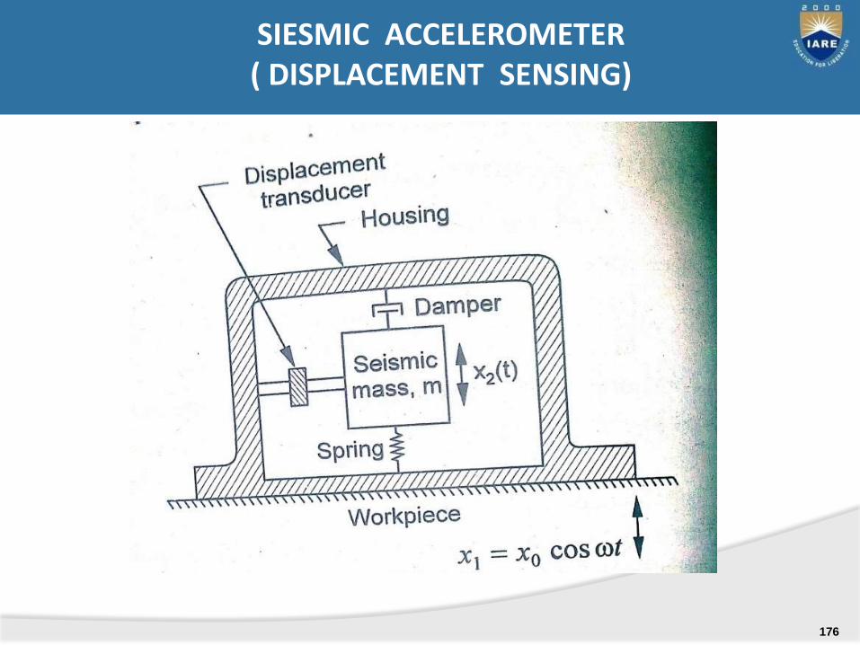
SIESMIC ACCELEROMETER( DISPLACEMENT SENSING)
176
I. Strain gauge accelerometer
II. Variable resistance vibration sensor
III. Piezo-electric accelerometer’
IV. LVDT accelerometer
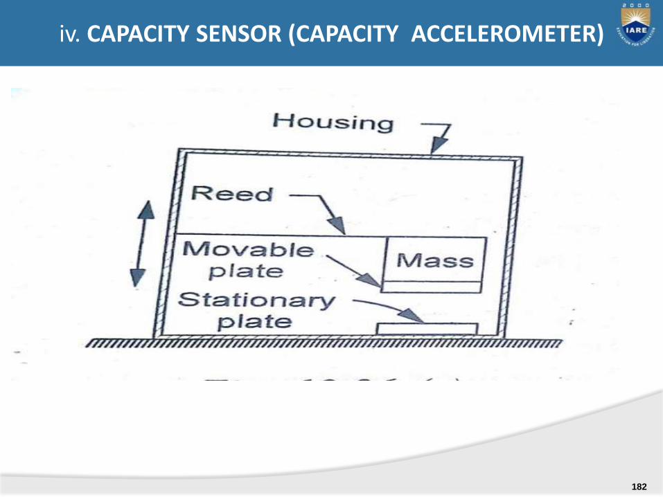
V. Capacitive vibration sensor
VI. Inductive vibration sensor
TRANSDUCERS USED FOR MEASUREMENT OF SEISMIC INSTRUMENTS OUTPUT
177
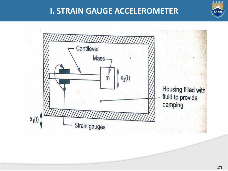
I. STRAIN GAUGE ACCELEROMETER
178
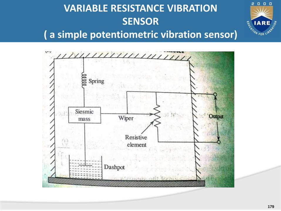
VARIABLE RESISTANCE VIBRATION SENSOR
( a simple potentiometric vibration sensor)
179
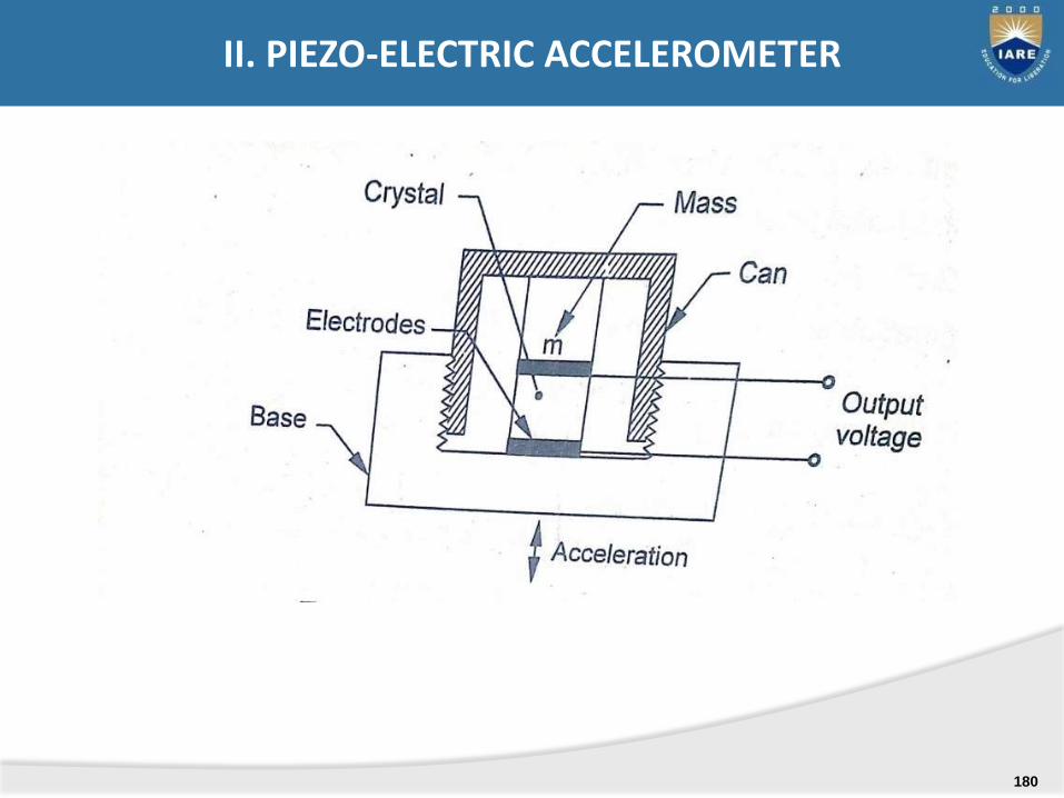
II. PIEZO-ELECTRIC ACCELEROMETER
180
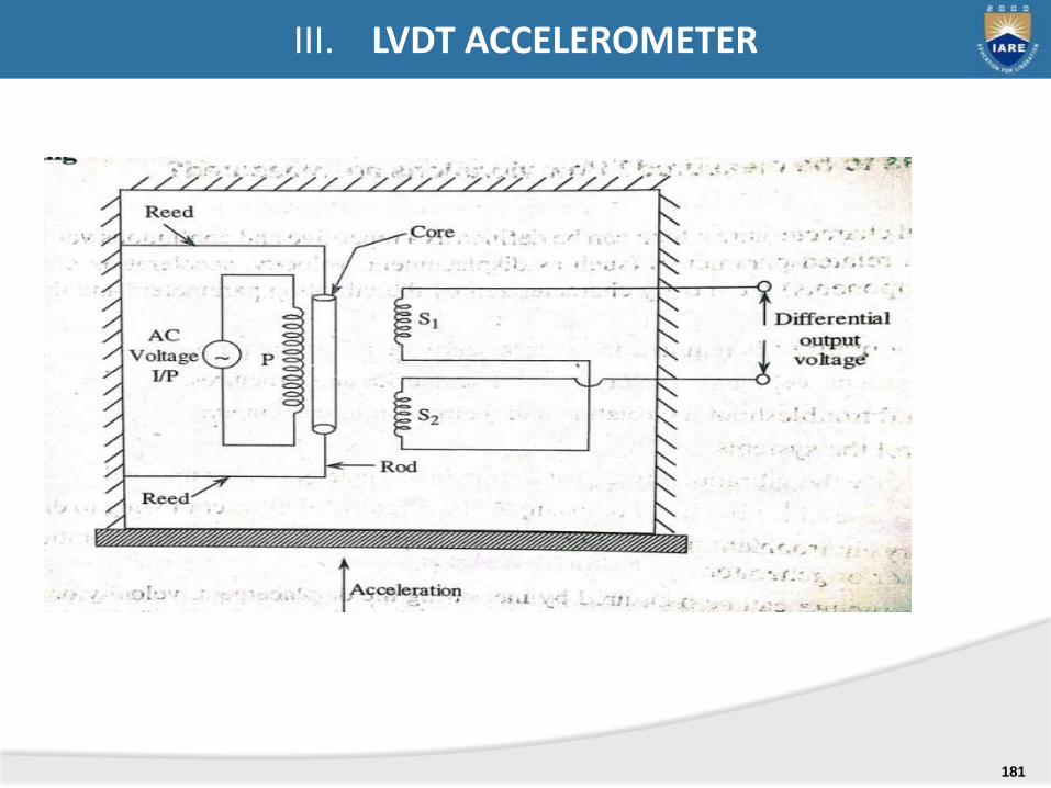
III. LVDT ACCELEROMETER
181
(
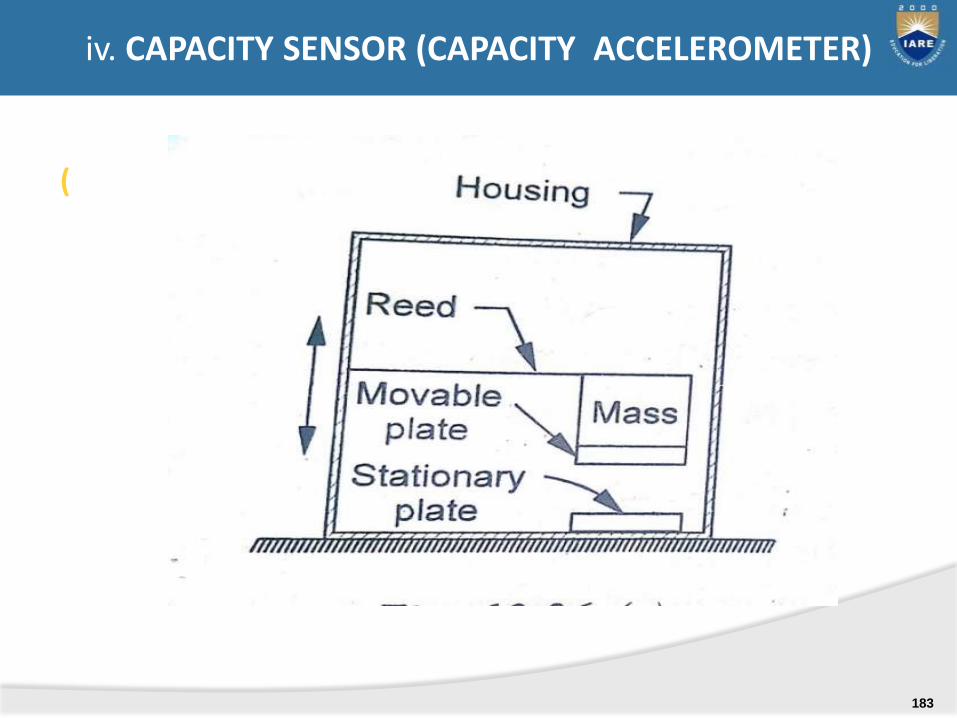
iv. CAPACITY SENSOR (CAPACITY ACCELEROMETER)
182
(
iv. CAPACITY SENSOR (CAPACITY ACCELEROMETER)
183

V. VARIABLE INDUCTION TYPE ACCELEROMETER
184
STRESS & STRAIN MEASUREMENTS:
Various types of stress and strain measurements -electrical strain gauge - gauge factor - method ofusage of resistance strain gauge for bending,compressive and tensile strains - usage for measuringtorque, Strain gauge Rosettes.
UNIT-IV
185

A strain gauge is a strain transducer, ie., device for measuring dimensional changes on the surface of a structural member under test.
Importance of strain measurement:
1. As a means of determining maxi. stress values
2. To avoid the use of large factor of safety in the design of aircraft, automatic control equipment due to mass/inertia considerations.
3. For experimental verification of strain in complex physical systems.
Strain gauge
186
I: Mechanical Strain gauges (Extensometers)
II. Electrical strain gauges: mechanical strain gauges are replaced with electrical strain gauges . Te capability to measure dynamic conditions at very frequncies.
III. photo-elastic
STRAIN MEASURING TECHNIQUES
187
While designing any strain gauge the following points are need to be considered for an accurate measure of strain
i. Extremely small size and negligible massii. Simple and easy attachment to the specimen under testiii. High speed of response.iv. High sensitivity in the direction of measured strain.v. Capability to indicate static, dynamic strain.vi. In sensitive to ambient conditions (temp, humidity,
vibration)vii. Inexpensive.viii. Availability in various types & sizes.All above are fulfilled by the bonded resistance strain
gauges.
REQUIREMENT OF STRAIN GAUGE
188
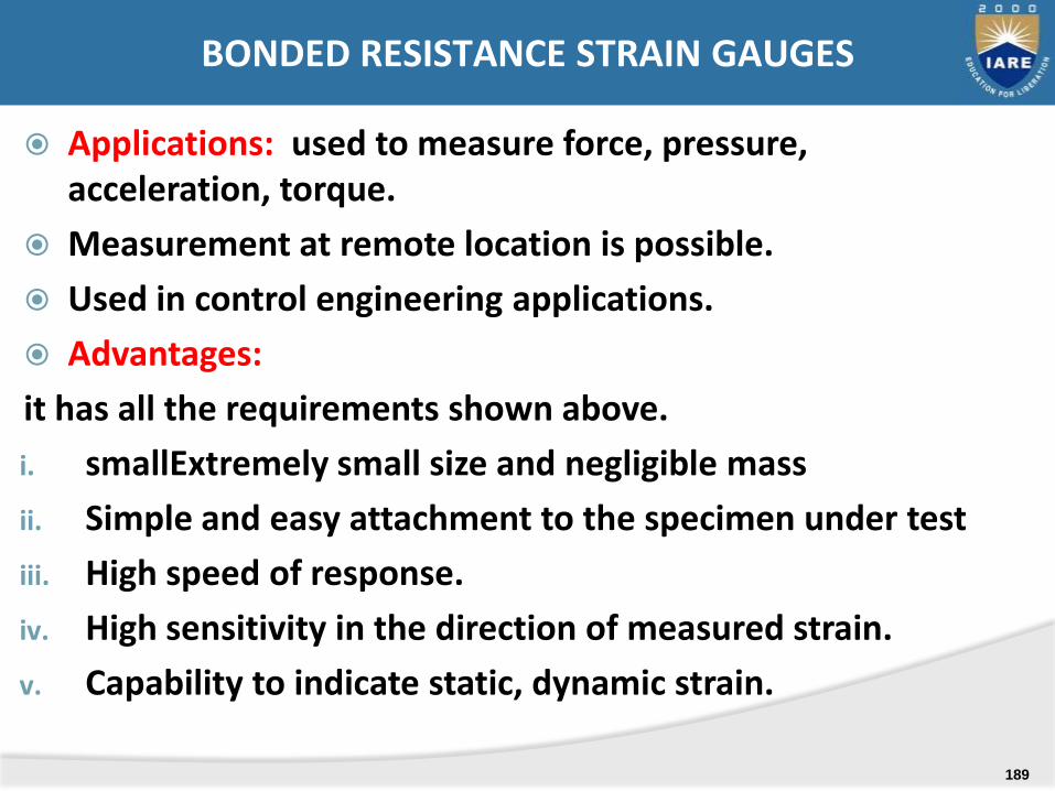
Applications: used to measure force, pressure, acceleration, torque.
Measurement at remote location is possible.
Used in control engineering applications.
Advantages:
it has all the requirements shown above.
i. smallExtremely small size and negligible mass
ii. Simple and easy attachment to the specimen under test
iii. High speed of response.
iv. High sensitivity in the direction of measured strain.
v. Capability to indicate static, dynamic strain.
BONDED RESISTANCE STRAIN GAUGES
189

1. Grid type strain gauge
FORMS OF BONDED RESISTANCE TYPE GAUGE
190
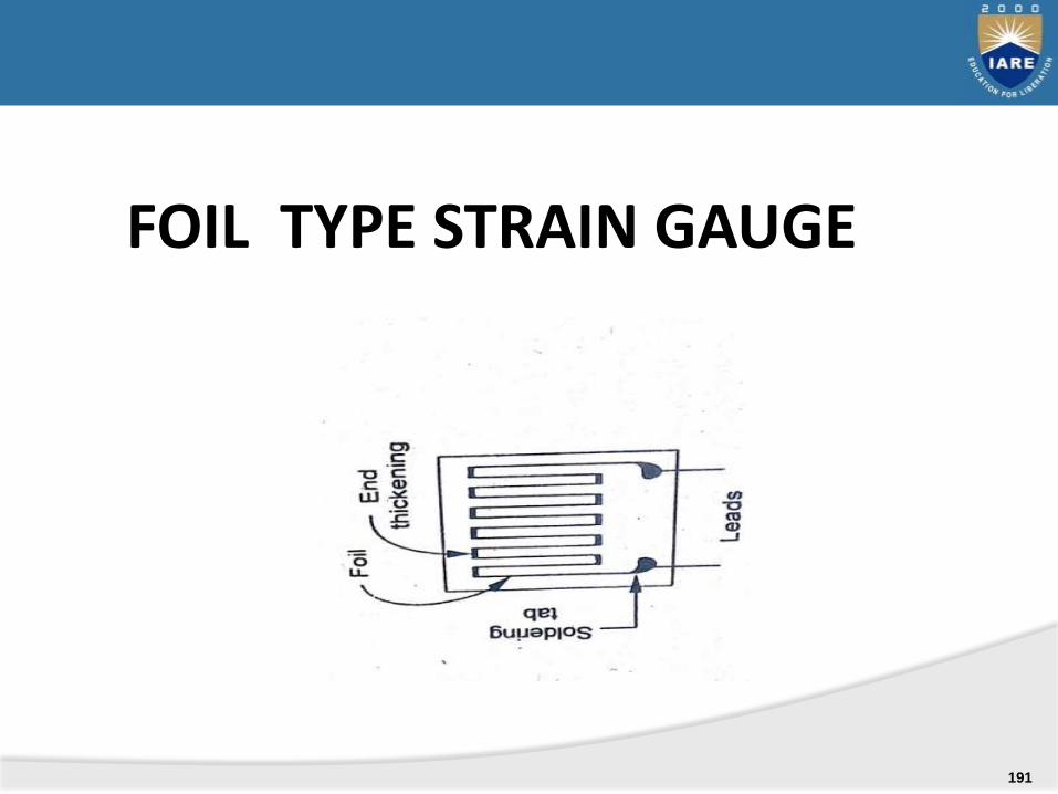
FOIL TYPE STRAIN GAUGE
191

SEMICONDUCTOR GAUGEOR PIEZO-RESISTIVE GAUGES
192
Selection and installation factors for bonded metallic strain gauges(Factors influencing metallic gauge characteristics and application)
1. Grid material & construction.
2. Backing material
3. Bonding material
4. Gauge protection.
5. Gauge configuration
193
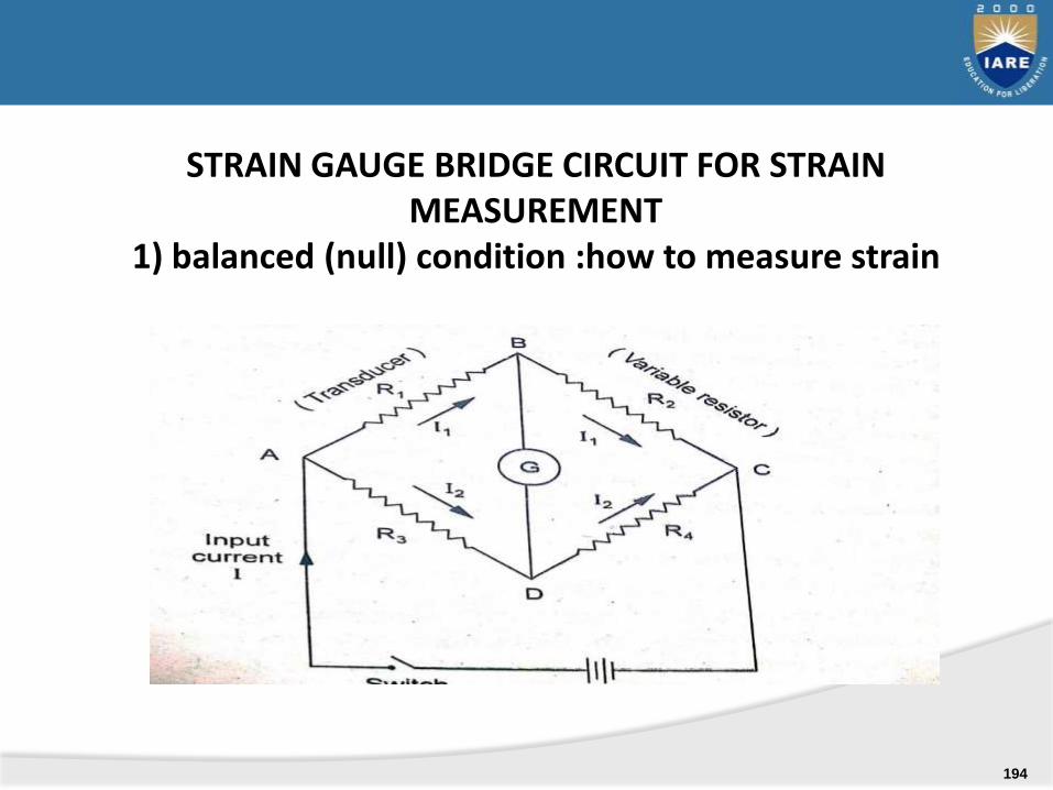
STRAIN GAUGE BRIDGE CIRCUIT FOR STRAIN MEASUREMENT
1) balanced (null) condition :how to measure strain
194
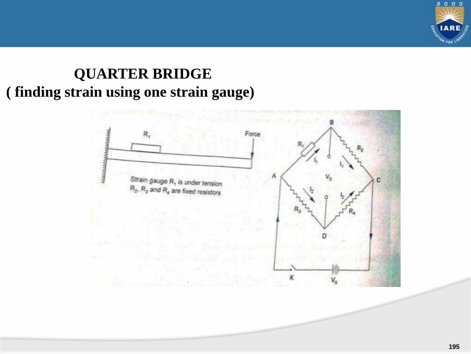
QUARTER BRIDGE
( finding strain using one strain gauge)
195
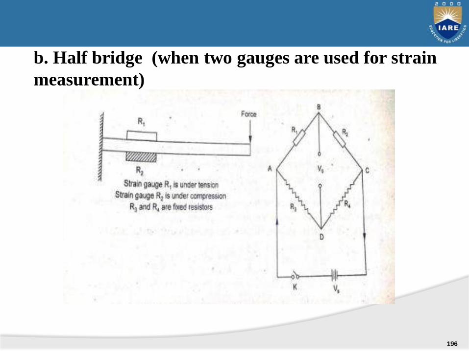
b. Half bridge (when two gauges are used for strain
measurement)
196
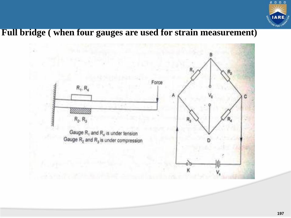
Full bridge ( when four gauges are used for strain measurement)
197
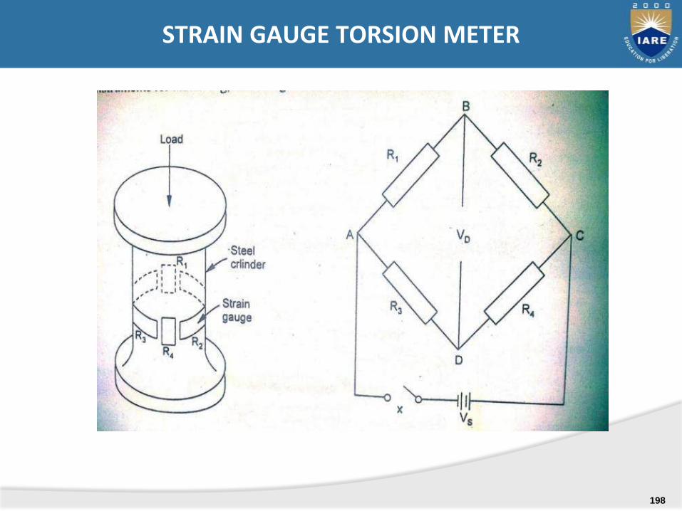
STRAIN GAUGE TORSION METER
198
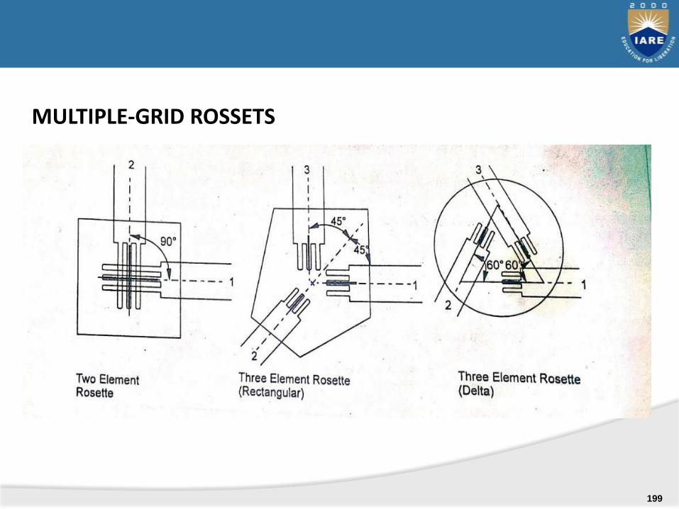
MULTIPLE-GRID ROSSETS
199

MEASUREMENT OF HUMIDITY
measurement of humidity.
moisture content in the gases
sling psychrometer
absorption psychrometer
dew point meter
200
Importance of humidity measurement & control
for human comforts.
Requirement of low humidity to prevent withering of food products and spoilage of dried eggs or dried milk.
Requirement of low humidity to prevent dry-out and cracking of leather , mildewing of canvas and leather
Protection of cargoes on ships from condensation damage.
Requisite moisture conditions for drying process.
201
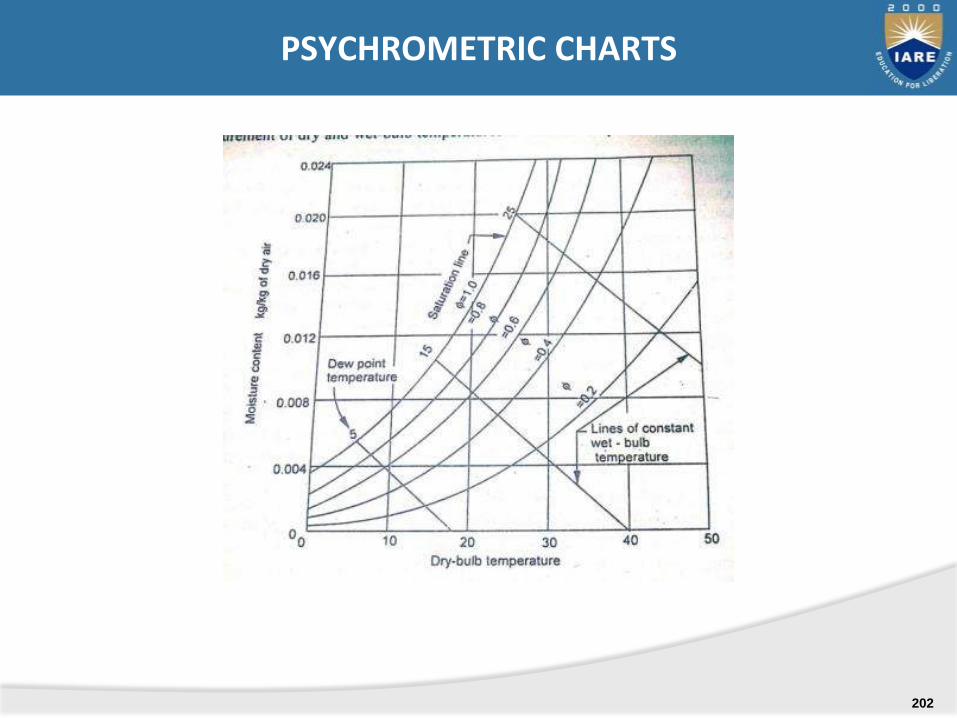
PSYCHROMETRIC CHARTS
202
1. Sling psychrometer
2. Gravimetric hygrometer
3. Absorption hygrometer
a. Mechanical humidity sensing absorption hygrometer
b. Electrical humidity sensing absorption hygrometer
4. Resistive hygrometers
5. Capacitive hygrometers
6. Microwave refracto meter
7. Crystal hygrometer
8. Aluminum oxide hygrometer
CLASSIFICATION OF INSTRUMENTS USED TOMEASURE MOISTURE AND HUMIDITY
203
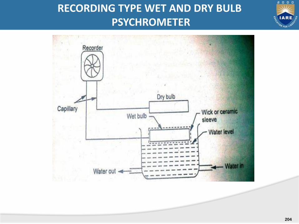
RECORDING TYPE WET AND DRY BULBPSYCHROMETER
204
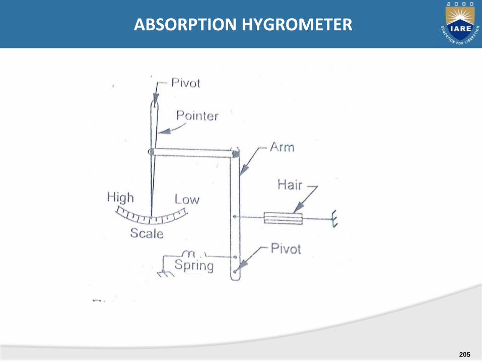
ABSORPTION HYGROMETER
205

ELECTRICAL HUMIDITY SENSING ABSORPTION HYGROMETER
206
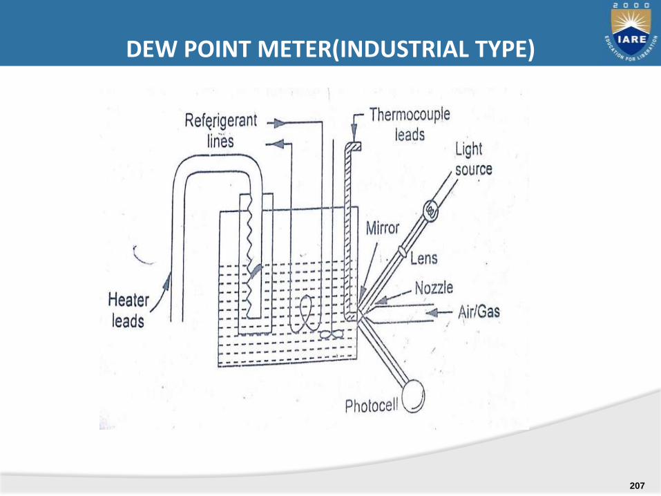
DEW POINT METER(INDUSTRIAL TYPE)
207
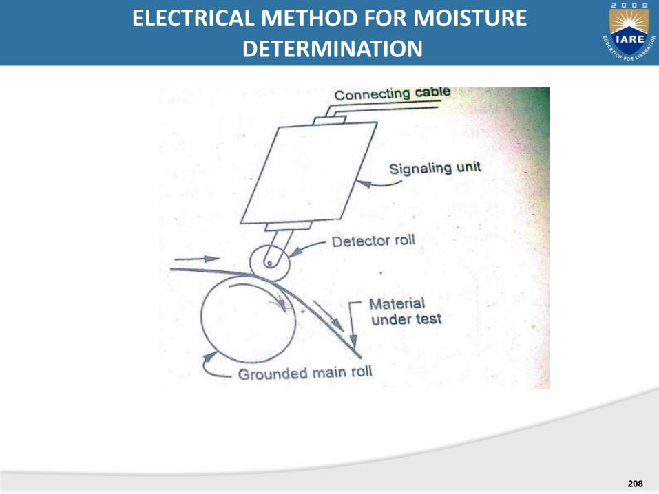
ELECTRICAL METHOD FOR MOISTUREDETERMINATION
208
MEASUREMENT OF FORCE, TORQUE AND POWER
ELASTIC FORCE METERS, LOAD CELLS, TORSION METERS, DYNAMOMETERS
UNIT-V
209

Scales and balances: Balancing the force against a known gravitational force on standard mass.
Hydraulic and pneumatic load cells: translating the force to fluid pressure and then measuring the resulting pressure.
Proving ring : Applying the force to some elastic member and then measuring the resulting deflection.
Applying the force to known mass and then measuring the resulting acceleration.
Balancing the force against a magnetic force developed by interaction of a magnet and current carrying coil.
MEASUREMENT METHODS WITH RELEVANT PRINCIPLE:
210
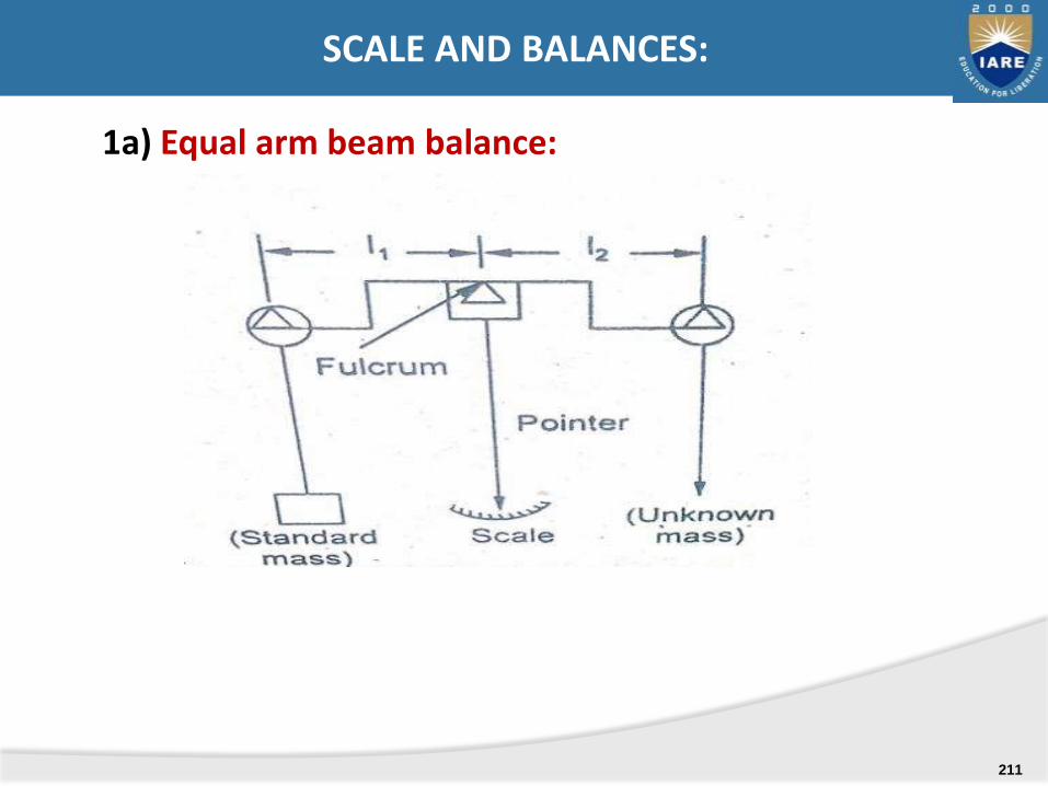
1a) Equal arm beam balance:
SCALE AND BALANCES:
211
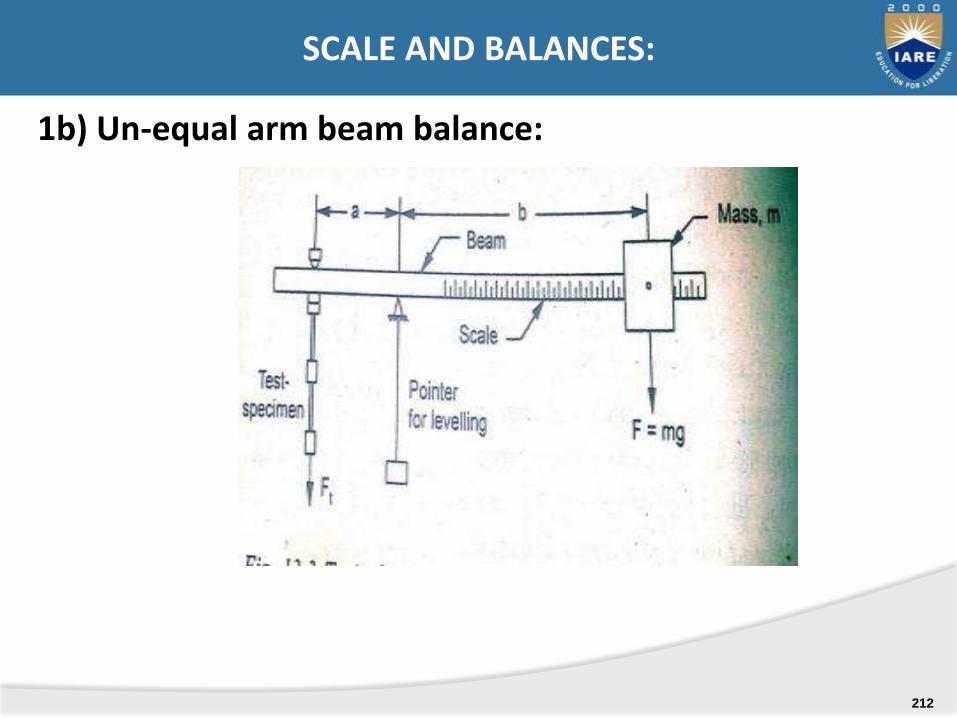
1b) Un-equal arm beam balance:
SCALE AND BALANCES:
212
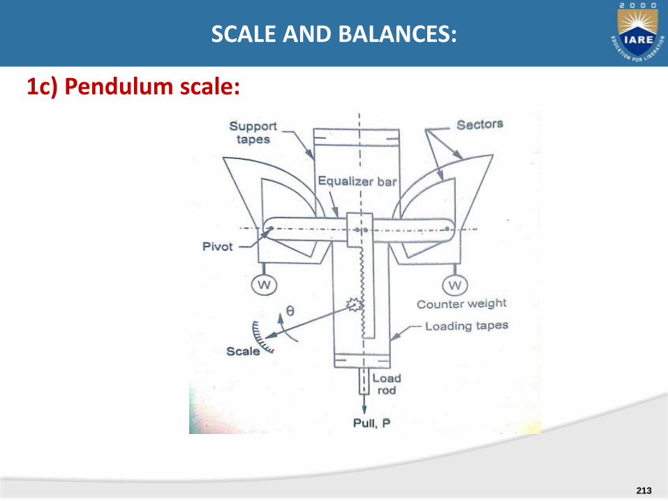
1c) Pendulum scale:
SCALE AND BALANCES:
213

Elastic force meters:
SCALE AND BALANCES:
214
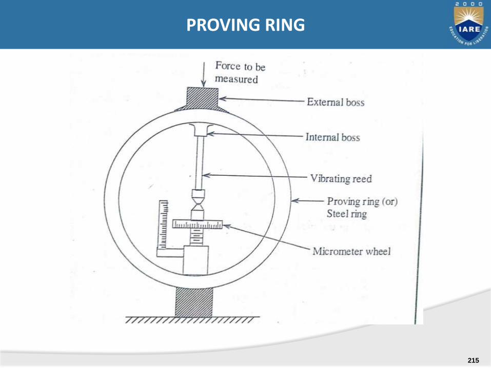
PROVING RING
215
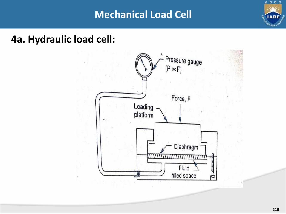
4a. Hydraulic load cell:
Mechanical Load Cell
216
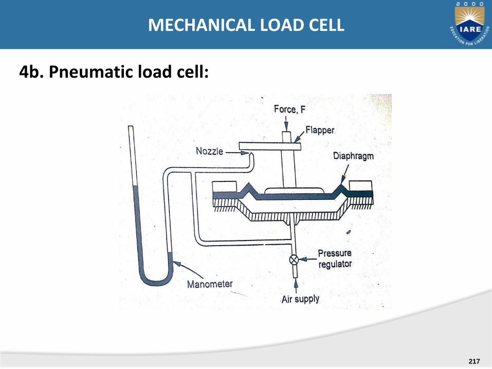
4b. Pneumatic load cell:
MECHANICAL LOAD CELL
217
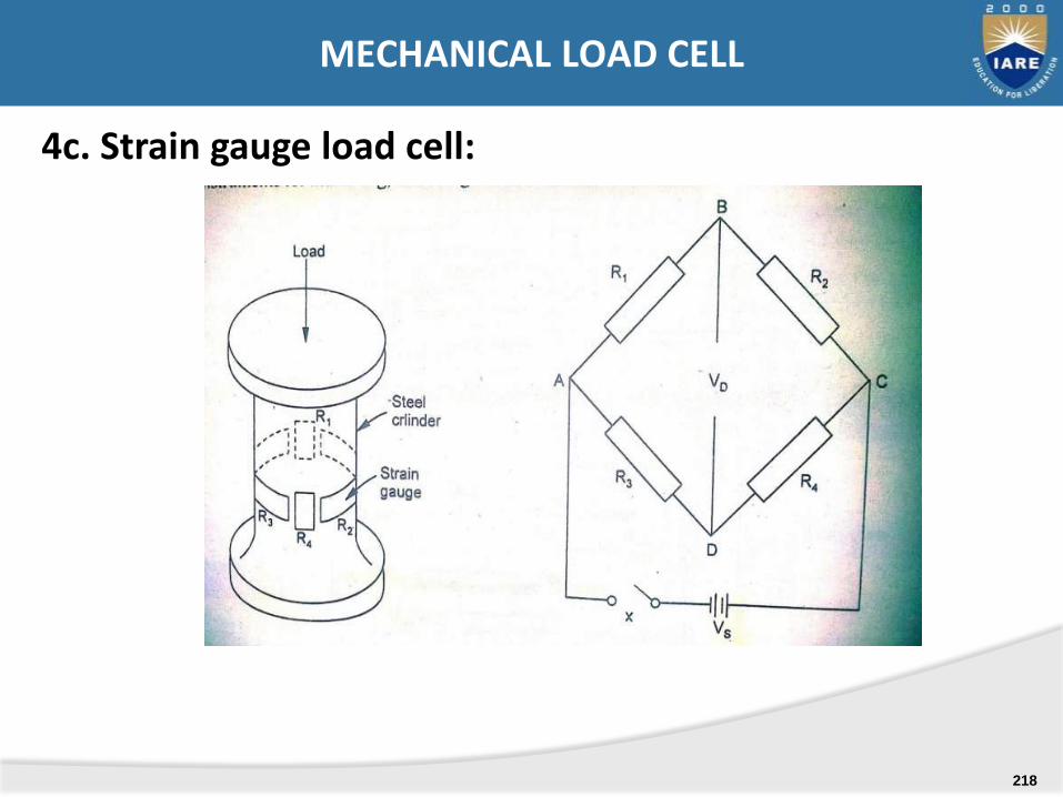
4c. Strain gauge load cell:
MECHANICAL LOAD CELL
218

1) Gravimetric method
2) Torque measurement of rotating machines
3) Mechanical torsion meter
4) Optical torsion meter
5) Electrical torsion meter
6) Strain gauge torsion meter
METHODS OF TORQUE MEASUREMENT
219
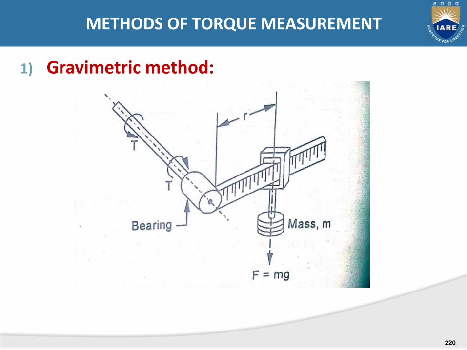
1) Gravimetric method:
METHODS OF TORQUE MEASUREMENT
220
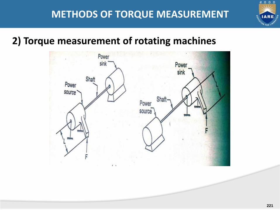
2) Torque measurement of rotating machines
METHODS OF TORQUE MEASUREMENT
221
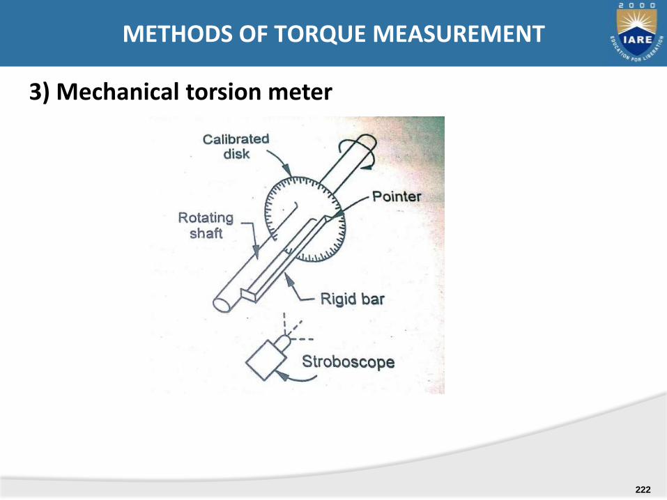
3) Mechanical torsion meter
METHODS OF TORQUE MEASUREMENT
222
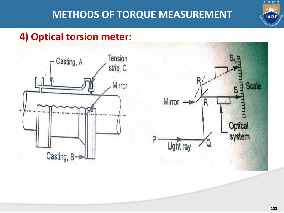
4) Optical torsion meter:
METHODS OF TORQUE MEASUREMENT
223
5) Electrical torsion meter
METHODS OF TORQUE MEASUREMENT
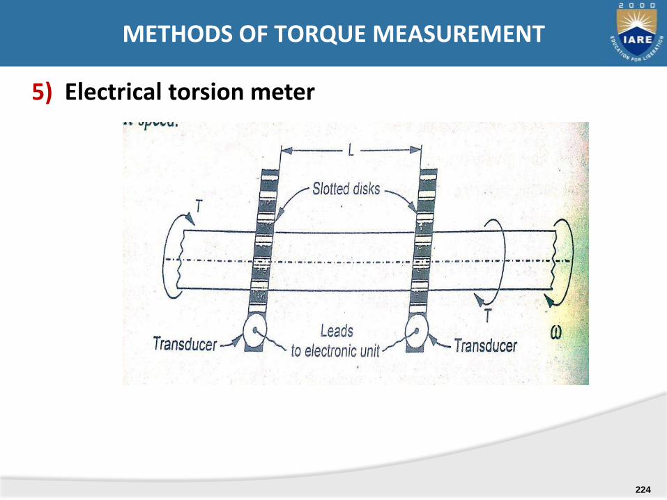
224
.
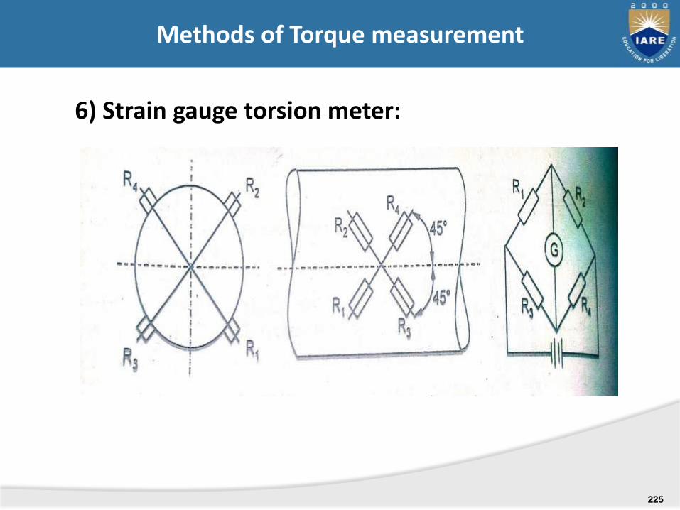
6) Strain gauge torsion meter:
Methods of Torque measurement
225
i. Absorption dynamometers
ii. Transmission dynamometers
iii. Driving dynamometers
Classification of Dynamometers
226

The device in which the energy is converted into heat by friction whilst being measured. The heat is dissipated to the surroundings where it generally serves no useful purpose. Absorption dynamometers are used when the test-machine is a power generator such as an engine, turbine and an electric motor.
Examples of absorption dynamometers are Ia. Mechanical brakes a.1 block type prony brake a.2 band type prony brake a.3 rope brake 1b. Hydraulic or fluid friction brake 1c. Eddy current dynamometers
ABSORPTION DYNAMOMETERS
227
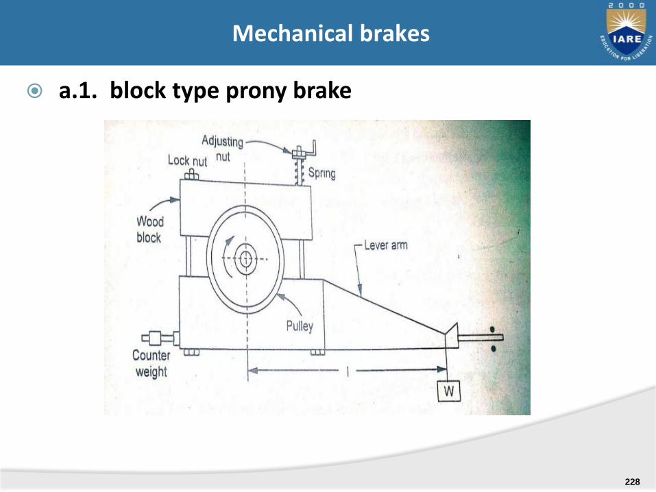
a.1. block type prony brake
Mechanical brakes
228
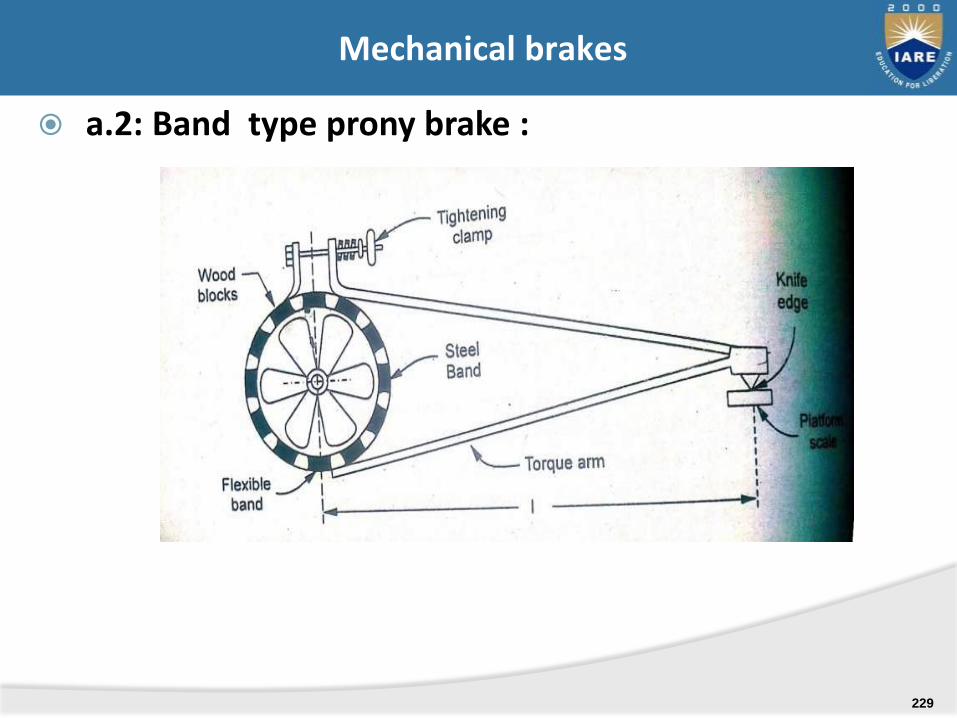
a.2: Band type prony brake :
Mechanical brakes
229
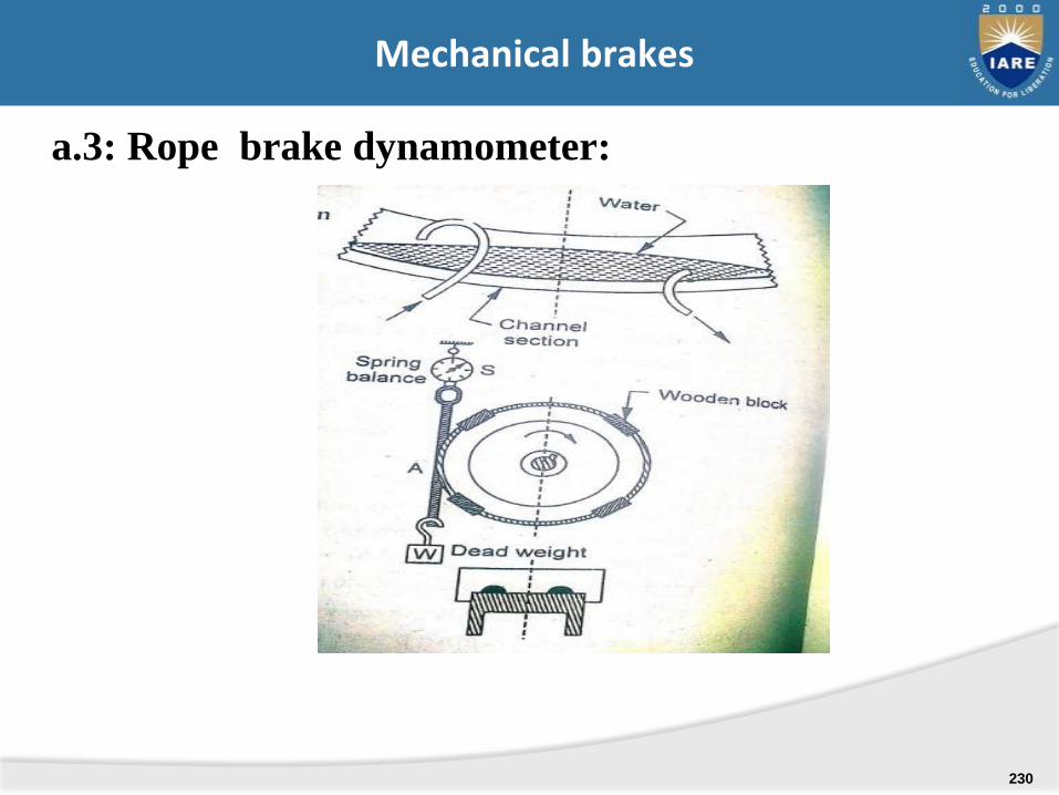
a.3: Rope brake dynamometer:
Mechanical brakes
230
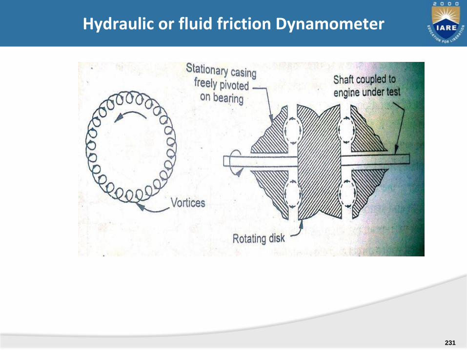
Hydraulic or fluid friction Dynamometer
231
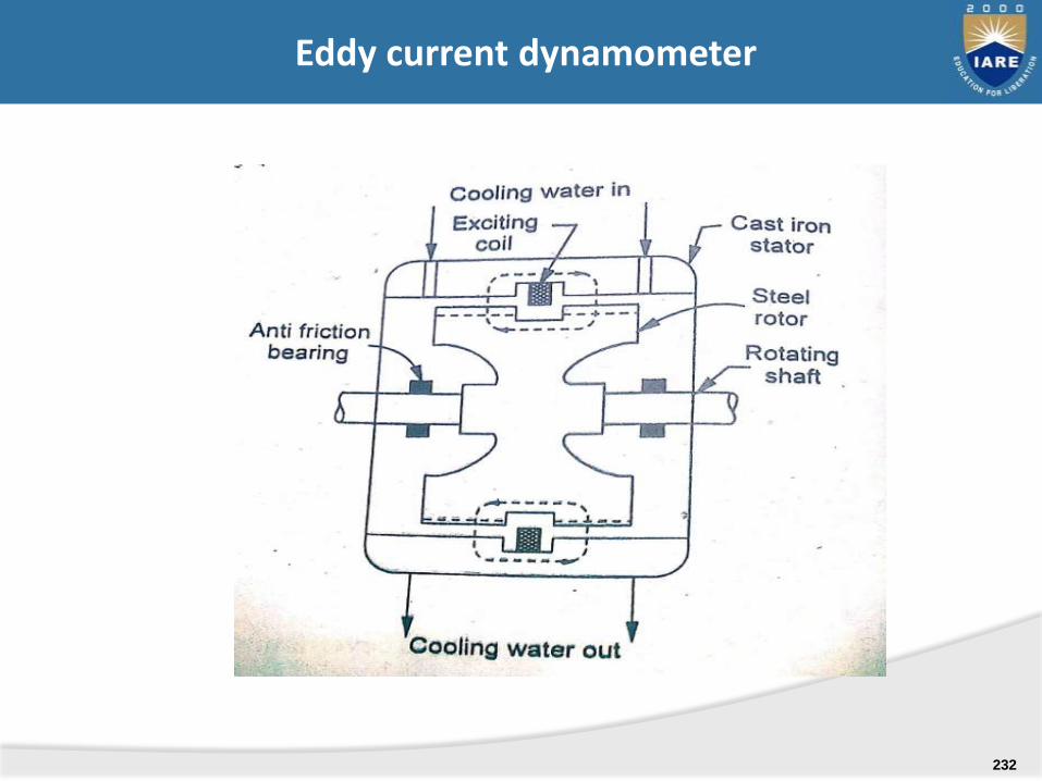
Eddy current dynamometer
232
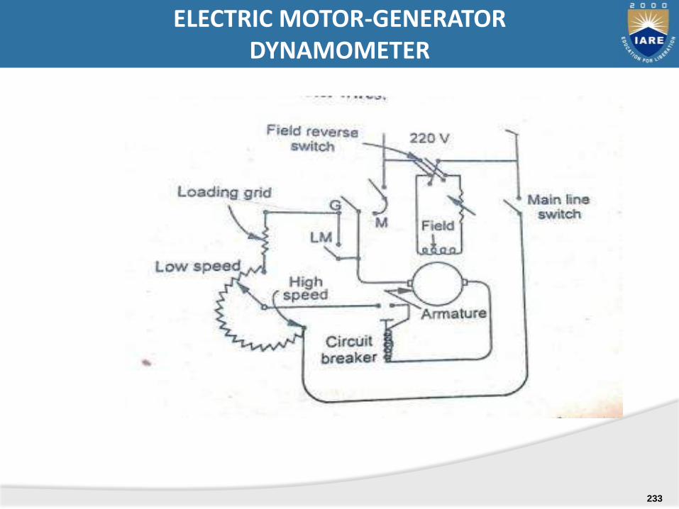
ELECTRIC MOTOR-GENERATOR DYNAMOMETER
233
.
ELEMNTS OF CONTROL SYSTEMS
Introduction, importance, Classification-open and closed systems, Servomechanisms- Examples with block diagrams-Temperature, speed and position control systems
UNIT-V
234
An assemblage of devices and components connectedor related by some form of regular interaction orinterdependence to form an organised whole andperform specified tasks. The system produces anoutput corresponding to a given input.
SYSTEM
235
-
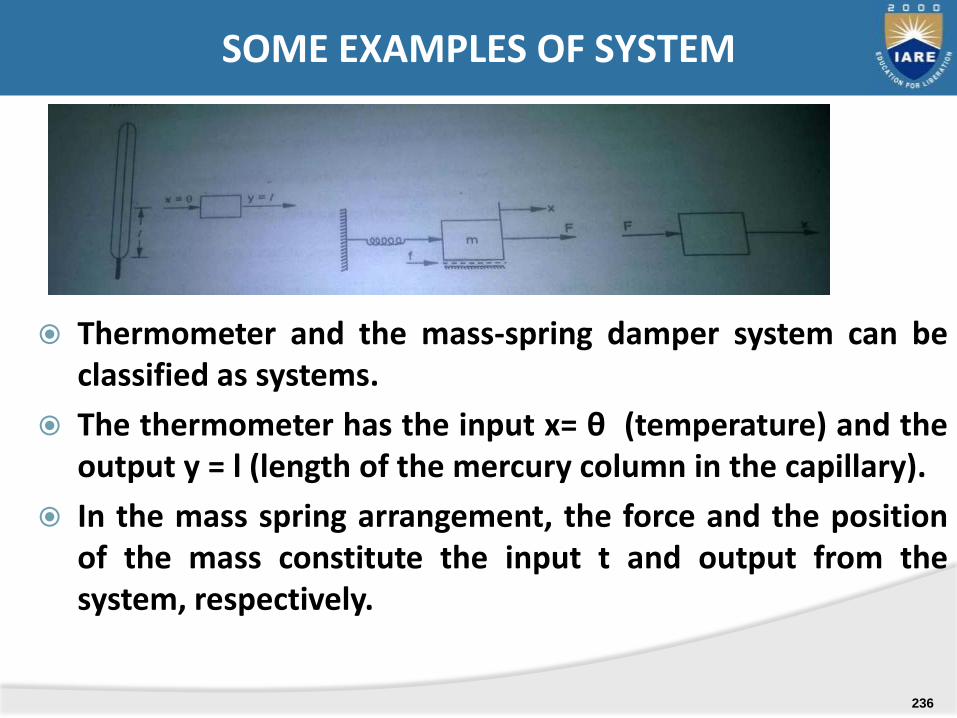
Thermometer and the mass-spring damper system can beclassified as systems.
The thermometer has the input x= θ (temperature) and theoutput y = l (length of the mercury column in the capillary).
In the mass spring arrangement, the force and the positionof the mass constitute the input t and output from thesystem, respectively.
SOME EXAMPLES OF SYSTEM
236

A THERMAL SYSTEM
CONTROL SYSTEMS- EXAMPLE
237
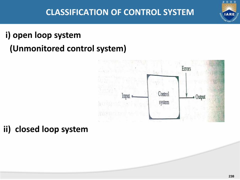
i) open loop system
(Unmonitored control system)
ii) closed loop system
CLASSIFICATION OF CONTROL SYSTEM
238
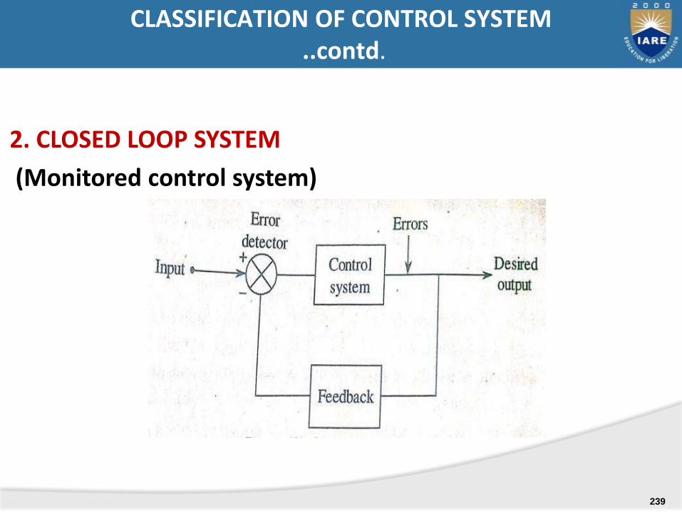
2. CLOSED LOOP SYSTEM
(Monitored control system)
CLASSIFICATION OF CONTROL SYSTEM ..contd.
239
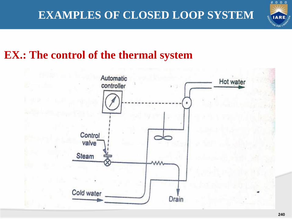
EX.: The control of the thermal system
EXAMPLES OF CLOSED LOOP SYSTEM
240
The closed loop systems listed above involve a continuous manual control by human operators and are classified as manual feed back or manual closed-loop systems.
Manually controlled system.
MANUAL CLOSED LOOP SYSTEM (MANUAL FEED BACK SYSTEM)
241
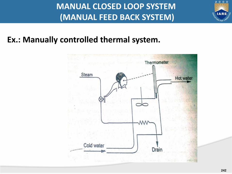
Ex.: Manually controlled thermal system.
MANUAL CLOSED LOOP SYSTEM(MANUAL FEED BACK SYSTEM)
242
Automatic control system: A close-loop system operating without human is called as automatic control system.
The automatic systems are the one controlledautomatically ( ie., not manually). One among theautomatic control systems is the feedback controlledthermal system. In this the human operator has beenreplaced by an automatic controller.
AUTOMATIC CONTROL SYSTEM
243

Ex.: THERMAL SYSTEM : automatic feedback control
AUTOMATIC CONTROL SYSTEM- EXAMPLES
244

Process, Plant, Controlled system (g2): a body , process ormachine of which a particular quantity or condition is to becontrolled, eg., a furnace , reactor or a spacecraft, etc.
Controlled variable (c): the quality or condition ( temperature,level, flow rate etc)characterising a process whose value is heldconstant by controller or is changed according to certain law.
Controlled medium: the process material in the controlledsystem or flowing through it in which the variable is to becontrolled.
Command: an input that is established or varied by some meansexternal to and independent of the feedback control system.
Manipulated variable (m): the quality or condition that is variesas a function of the actuating signal so as to change the value ofthe control element (g1 ).
Actuating signal ( e ): an algebraic sum of the reference input ‘r’and the primary feedback ‘b’. The actuating signal is also calledthe error or control action.
CONTROL SYSTEMS TERMINOLOGY
245
Primary feed-back signal (b): a function f thecontrolled output ‘c’, which is compared with thereference input to obtain the actuating signal.
Error-detector: an element that detects the feed-back: essentially it is a summing point which gives thealgebraic summation of two or more signals. Thedirection of flow of information is indicated by arrowsand the algebraic nature of summation by plus orminus sign.
CONTROL SYSTEMS TERMINOLOGY .. Contd.
246
Disturbance ( u ): an undesirable variable applied to the system which tends affect adversely the value of the variable being controlled. The process disturbance may be due to changes in set point, supply, demand, environmental and other associated variables.
Feed-back element ( h ) : an element of the feed-back control system that establishes a functional relationship between the controlled variable ‘c’ and the feedback signal ‘b’.
Control element ( g1 ): an element that is required to generate the appropriate control signal ( manipulated variable) ‘m’ applied to the plant.
Forward and backward paths: the transmission path from the actuating signal ‘e’ to to the controlled output ‘c’ constitutes the forward path. The backward path is the transmission path from the controlled output ‘c’ to the primary feed-back signal ‘b’.
CONTROL SYSTEMS TERMINOLOGY
.. Contd.
247

NEGATIVE FEEDBACK SIGNAL
248
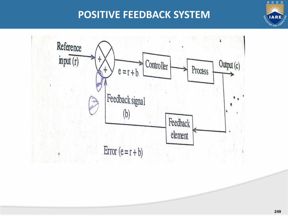
POSITIVE FEEDBACK SYSTEM
249
A servomechanism: is an automatic control system inwhich the controlled variable is mechanical position(displacement, or a time derivative f displacementsuch as velocity and acceleration. The output isdesigned to follow a continuously changing input ordesired variable ( demand signal). Theservomechanisms are inherently fast acting ( smalltime lag with response time in the order ofmilliseconds) and usually employ electric or hydraulicactuation.
SERVOMECHANISM PROCESS CONTROL
250
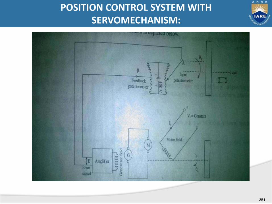
POSITION CONTROL SYSTEM WITH SERVOMECHANISM:
251

252


