44
Conducting Value INSTRUMENTATION, CONTROL AND THERMOCOUPLE CABLES 400/7 1

Instrumentation and Control Cables
Conducting Value
INSTRUMENTATION, CONTROL AND THERMOCOUPLE CABLES
400/7 1
ISO 9001:2008Certificate No. CS1-249
ISO 14001:2004n. 9191.CVCL
ISO 9001:2008n. 9125.CAVL
GOST ISO 9001-2011 (ISO 9001:2008)
certification N CдC.TII.CM.04293-14
MANAGEMENTSYSTEMS
Assessed to ISO 9001:2008Cert/LPCB ref. 217
Our commitment to environmentally friendly products.CAVICEL is committed to providing our customers with environmentally friendly products in compliance with the European Union (EU) RoHS Directive (Restriction of Hazardous Substances) and REACH Regulation (Registration, Evaluation, Authorization and Restriction of Chemicals).
REACHRoHS
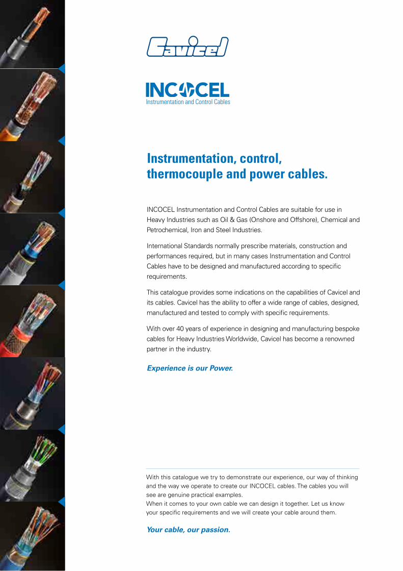
Instrumentation, control, thermocouple and power cables.
INCOCEL Instrumentation and Control Cables are suitable for use in Heavy Industries such as Oil & Gas (Onshore and Offshore), Chemical and Petrochemical, Iron and Steel Industries.
International Standards normally prescribe materials, construction and performances required, but in many cases Instrumentation and Control Cables have to be designed and manufactured according to specific requirements.
This catalogue provides some indications on the capabilities of Cavicel and its cables. Cavicel has the ability to offer a wide range of cables, designed, manufactured and tested to comply with specific requirements.
With over 40 years of experience in designing and manufacturing bespoke cables for Heavy Industries Worldwide, Cavicel has become a renowned partner in the industry.
Experience is our Power.
With this catalogue we try to demonstrate our experience, our way of thinking and the way we operate to create our INCOCEL cables. The cables you will see are genuine practical examples.When it comes to your own cable we can design it together. Let us know your specific requirements and we will create your cable around them.
Your cable, our passion.
Instrumentation and Control Cables
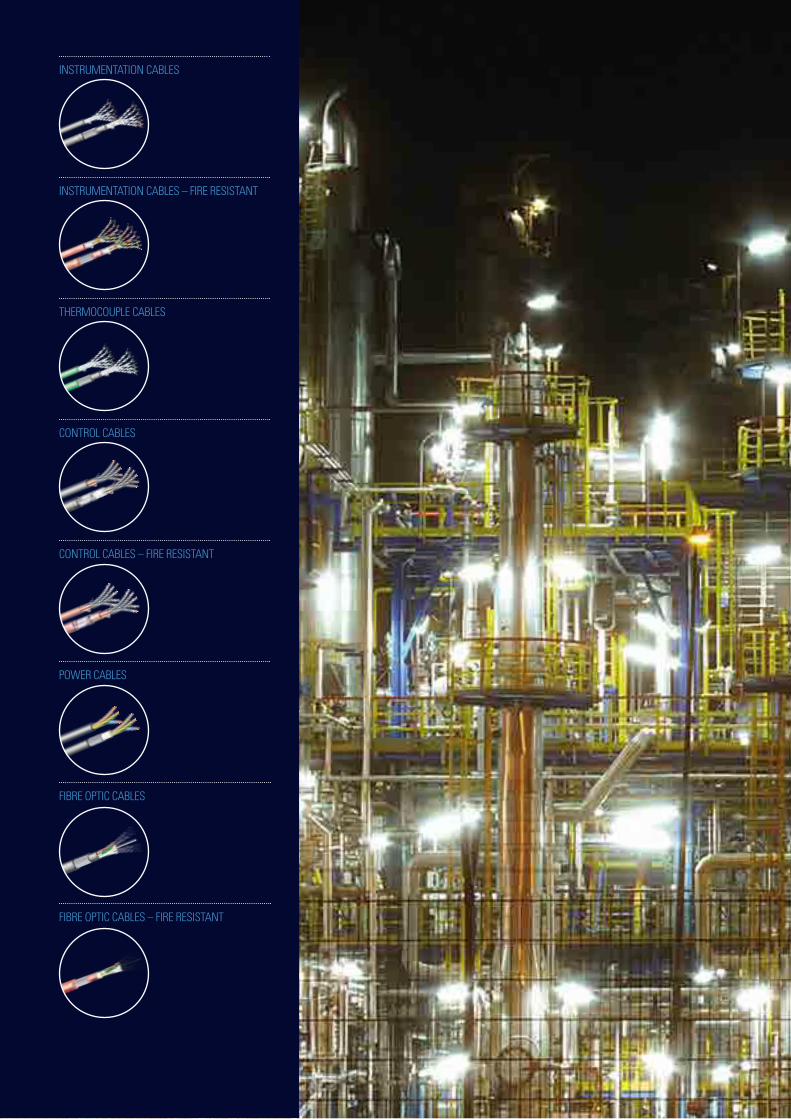
INSTRUMENTATION CABLES
INSTRUMENTATION CABLES – FIRE RESISTANT
THERMOCOUPLE CABLES
CONTROL CABLES
CONTROL CABLES – FIRE RESISTANT
POWER CABLES
FIBRE OPTIC CABLES
FIBRE OPTIC CABLES – FIRE RESISTANT
INSTRUMENTATION, CONTROL,THERMOCOUPLE AND POWER CABLES.
Instrumentation and Control Cables
CONSTRUCTION AND GENERAL INFORMATION
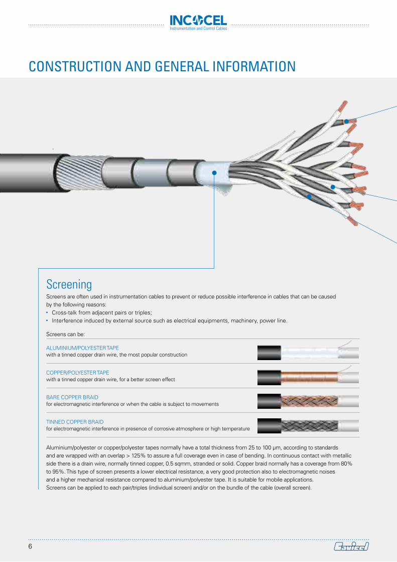
ScreeningScreens are often used in instrumentation cables to prevent or reduce possible interference in cables that can be caused by the following reasons:•• Cross-talk from adjacent pairs or triples;•• Interference induced by external source such as electrical equipments, machinery, power line.
Screens can be:
ALUMINIUM/POLYESTER TAPE with a tinned copper drain wire, the most popular construction
COPPER/POLYESTER TAPE with a tinned copper drain wire, for a better screen effect
BARE COPPER BRAID for electromagnetic interference or when the cable is subject to movements
TINNED COPPER BRAID for electromagnetic interference in presence of corrosive atmosphere or high temperature
Aluminium/polyester or copper/polyester tapes normally have a total thickness from 25 to 100 μm, according to standards and are wrapped with an overlap > 125% to assure a full coverage even in case of bending. In continuous contact with metallic side there is a drain wire, normally tinned copper, 0.5 sqmm, stranded or solid. Copper braid normally has a coverage from 80% to 95%. This type of screen presents a lower electrical resistance, a very good protection also to electromagnetic noises and a higher mechanical resistance compared to aluminium/polyester tape. It is suitable for mobile applications.Screens can be applied to each pair/triples (individual screen) and/or on the bundle of the cable (overall screen).
6
Instrumentation and Control Cables
CablingInstrumentation cables can be laid up in:•• Concentric construction•• Pairs•• Triples•• QuadsIn case of quads, this is normally considered a two-pair element, the connection is done using opposed cores for one circuit.Twisting is important to reduce noise in circuits and also the lay of twist in some constructions must be carefully considered.In some application, in order to reduce interference between cabling elements, the length of twist of adjacent elements (pairs) must be different. With individual screen on each element, the above is not necessary.Communication wire or couple can be added to total cabling of elements, if required.
InsulationMany materials can be used as insulation for instrumentation cables: working conditions need to be taken into consideration to choose the right material.Material can be divided into two classes: thermoplastic and thermoset (crosslinked).Thermoplastic material are more sensitive to high temperatures, as material melts at the increase of temperature, while thermoset, due to stable polymeric chain bonds are more resistant to temperature and deformation.In the first class there are the most popular insulations for these types of cables such as PE and PVC for general installation conditions and the new generation of LSZH thermoplastic materials (low smoke zero halogen).Second class includes, for example, XLPE, silicone rubber, other rubbers such as EPR, HEPR, EVA.Special technopolymer can be used in case of specific installation condition, such as fluoropolymer or technopolymer materials.For fire resistant cables two types of insulation are used: silicone or mica tape plus XLPE (or other thermoset compounds). Table “Materials” on page 16 is a general guide for the choice of insulation and jacketing materials.
Core identificationIdentification of conductors/pairs can be by means of colours, by inscription of a number on the cores or by numbered polyesther film on pairs. This has to be defined in the order.
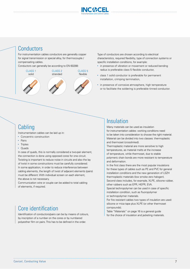
ConductorsFor instrumentation cables conductors are generally copper for signal transmission or special alloy, for thermocouple /compensating cables.Conductors can generally be according to EN 60288:
CLASS 1solid
CLASS 2stranded
CLASS 5flexible
Type of conductors are chosen according to electrical characteristics, required flexibility, type of connection systems or specific installation conditions, for example:•• in presence of vibration or movement or reduced bending
radius is preferable class 5 flexible conductor,
•• class 1 solid conductor is preferable for permanent installation, crimping termination,
•• in presence of corrosive atmosphere, high temperature or to facilitate the soldering is preferable tinned conductor.
7Cavicel, Conducting Value
Instrumentation and Control Cables
CONSTRUCTION AND GENERAL INFORMATION
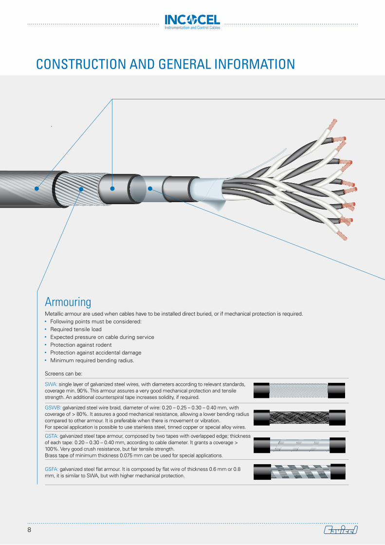
ArmouringMetallic armour are used when cables have to be installed direct buried, or if mechanical protection is required.•• Following points must be considered:•• Required tensile load•• Expected pressure on cable during service•• Protection against rodent•• Protection against accidental damage•• Minimum required bending radius.
Screens can be:
SWA: single layer of galvanized steel wires, with diameters according to relevant standards, coverage min. 90%. This armour assures a very good mechanical protection and tensile strength. An additional counterspiral tape increases solidity, if required.
GSWB: galvanized steel wire braid, diameter of wire: 0.20 – 0.25 – 0.30 – 0.40 mm, with coverage of > 80%. It assures a good mechanical resistance, allowing a lower bending radius compared to other armour. It is preferable when there is movement or vibration.For special application is possible to use stainless steel, tinned copper or special alloy wires.
GSTA: galvanized steel tape armour, composed by two tapes with overlapped edge; thickness of each tape: 0.20 – 0.30 – 0.40 mm, according to cable diameter. It grants a coverage > 100%. Very good crush resistance, but fair tensile strength.Brass tape of minimum thickness 0.075 mm can be used for special applications.
GSFA: galvanized steel flat armour. It is composed by flat wire of thickness 0.6 mm or 0.8 mm, it is similar to SWA, but with higher mechanical protection.
8
Instrumentation and Control Cables
SheathMany compounds can be used as internal/external protection of cables. Working condition need to be considered for the right choice.PVC, PE and LSZH are the most popular materials, but we have to consider that different grades are available to meet specific working conditions.Anyway the following conditions have to be evaluated:•• Type of installation (indoor/outdoor, direct buried…)•• Possible presence of humidity, oil, chemicals…•• Behaviour in case of a fire (fire propagation, fire resistance,
emission of gases and smoke...)•• Range of temperature•• UV resistance in case of sun exposureTable “Materials” on page 16 is a general guide for the choice of insulation and jacketing materials.
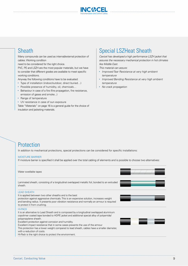
ProtectionIn addition to mechanical protections, special protections can be considered for specific installations:
MOISTURE BARRIERIf moisture barrier is specified it shall be applied over the total cabling of elements and is possible to choose two alternatives:
Water swellable tapes
Laminated sheath, consisting of a longitudinal overlapped metallic foil, bonded to an extruded sheath.
LEAD SHEATHIt is applied between two other sheaths and is the best protection against aggressive chemicals. This is an expensive solution, increases weight and bending radius. It presents poor vibration resistance and normally an armour is required to protect it from crushing.
HI-PACKIt is an alternative to Lead Sheath and is composed by a longitudinal overlapped aluminium copolimer coated tape bonded to HDPE jacket and additional special alloy of polyamide/polypropylene sheath.Excellent protection against corrosion and humidity.Excellent impact resistance that in some cases prevents the use of the armourThis protection has a lower weight compared to lead sheath, cables have a smaller diameter, with a reduction of costs.Hi-Pack is the right choice to protect the environment.
Special LSZHeat SheathCavicel has developed a high performance LSZH jacket that assures the necessary mechanical protection in hot climates like Middle East.This material can assure:•• Improved Tear Resistance at very high ambient
temperature•• Improved Bending Resistance at very high ambient
temperature•• No crack propagation
9Cavicel, Conducting Value
Instrumentation and Control Cables
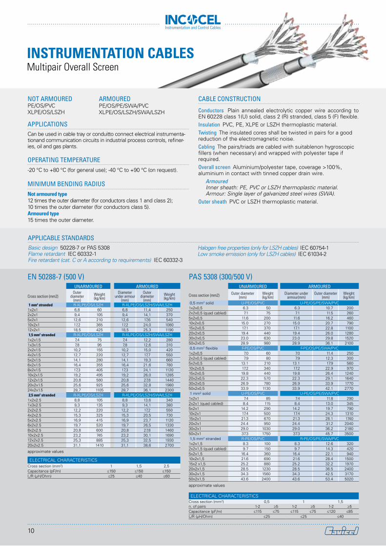
APPLICATIONSCan be used in cable tray or conduitto connect electrical instrumenta-tionand communication circuits in industrial process controls, refiner-ies, oil and gas plants.
OPERATING TEMPERATURE-20 °C to +80 °C (for general use); -40 °C to +90 °C (on request).
MINIMUM BENDING RADIUSNot armoured type12 times the outer diameter (for conductors class 1 and class 2); 10 times the outer diameter (for conductors class 5).Armoured type15 times the outer diameter.
NOT ARMOUREDPE/OS/PVCXLPE/OS/LSZH
CABLE CONSTRUCTION
Conductors Plain annealed electrolytic copper wire according to EN 60228 class 1(U) solid, class 2 (R) stranded, class 5 (F) flexible.Insulation PVC, PE, XLPE or LSZH thermoplastic material.Twisting The insulated cores shall be twisted in pairs for a good reduction of the electromagnetic noise.Cabling The pairs/triads are cabled with suitablenon hygroscopic fillers (when necessary) and wrapped with polyester tape if required.Overall screen Aluminium/polyester tape, coverage >100%, aluminium in contact with tinned copper drain wire.
ArmouredInner sheath: PE, PVC or LSZH thermoplastic material.Armour: Single layer of galvanized steel wires (SWA).
Outer sheath PVC or LSZH thermoplastic material.
UNARMOURED ARMOURED
Cross section (mm2)Outer
diameter (mm)
Weight(kg/km)
Diameter under armour
(mm)
Outer diameter
(mm)Weight(kg/km)
1 mm2 stranded R-XLPE/OS/LSZH R-XLPE/OS/LSZH/SWA/LSZH1x2x1 6,8 60 6,8 11,4 2502x2x1 9,4 105 9,4 14,1 3705x2x1 12,6 210 12,6 17,6 54010x2x1 17,2 365 17,2 24,0 108012x2x1 18,5 425 18,5 25,3 11901,5 mm2 stranded R-XLPE/OS/LSZH R-XLPE/OS/LSZH/SWA/LSZH
1x2x1.5 7,4 75 7,4 12,2 2801x3x1.5 7,8 95 7,8 12,6 3102x2x1.5 10,2 155 10,2 15,0 4204x2x1.5 12,7 220 12,7 17,7 5505x2x1.5 14,1 280 14,1 19,3 6606x2x1.5 16,4 355 16,4 21,6 7808x2x1.5 17,3 405 17,3 24,1 112010x2x1.5 19,2 495 19,2 26,0 128512x2x1.5 20,8 580 20,8 27,8 144020x2x1.5 25,6 925 25,6 32,8 198024x2x1.5 28,7 1105 28,7 36,1 23002,5 mm2 stranded R-XLPE/OS/LSZH R-XLPE/OS/LSZH/SWA/LSZH
1x2x2.5 8,8 105 8,8 13,6 3401x3x2.5 9,3 135 9,3 14,1 3802x2x2.5 12,2 220 12,2 17,2 5504x2x2.5 15,3 325 15,3 20,5 7305x2x2.5 16,9 415 16,9 23,7 11206x2x2.5 19,7 520 19,7 26,5 13308x2x2.5 20,8 600 20,8 27,8 146010x2x2.5 23,2 745 23,2 30,1 169012x2x2.5 25,3 885 25,3 32,5 193020x2x2.5 31,1 1410 31,1 38,6 2700
approximate values
ELECTRICAL CHARACTERISTICSCross section (mm2) 1 1,5 2,5Capacitance (pF/m) ≤150 ≤150 ≤150L/R (µH/Ohm) ≤25 ≤40 ≤60
EN 50288-7 (500 V) PAS 5308 (300/500 V)
APPLICABLE STANDARDSBasic design 50228-7 or PAS 5308Flame retardant IEC 60332-1Fire retardant (cat. C or A according to requirements) IEC 60332-3
UNARMOURED ARMOURED
Cross section (mm2) Outer diameter(mm)
Weight(kg/km)
Diameter under armour(mm)
Outer diameter(mm)
Weight(kg/km)
0,5 mm2 solid U-PE/OS/PVC U-PE/OS/PE/SWA/PVC1x2x0,5 6.3 50 6.3 10.7 2002x2x0,5 (quad cabled) 7.1 75 7.1 11.5 2605x2x0,5 11.6 200 11.6 16.2 46010x2x0,5 15.0 270 15.0 20.7 79015x2x0,5 17.1 370 17.1 22.8 110020x2x0,5 19.4 440 19.4 26.0 128030x2x0,5 23.0 630 23.0 29.8 152050x2x0,5 28.9 980 28.9 36.1 21000,5 mm2 flexible F-PE/OS/PVC F-PE/OS/PE/SWA/PVC
1x2x0,5 7.0 60 7.0 11.4 2502x2x0,5 (quad cabled) 7.9 80 7.9 12.3 3005x2x0,5 13.1 210 13.1 17.9 56010x2x0,5 17.2 340 17.2 22.9 97015x2x0,5 19.8 440 19.8 26.4 124020x2x0,5 22.3 570 22.3 29.1 164030x2x0,5 26.9 780 26.9 33.9 177050x2x0,5 33.9 1130 33.9 42.1 27701 mm2 solid U-PE/OS/PVC U-PE/OS/PE/SWA/PVC
1x2x1 7.4 85 7.4 11.8 2902x2x1 (quad cabled) 8.4 115 8.4 13.0 3455x2x1 14.2 290 14.2 19.7 79010x2x1 17.4 500 17.4 24.3 131015x2x1 21.3 670 21.3 28.1 174020x2x1 24.4 950 24.4 31.2 204030x2x1 29.0 1030 29.0 36.2 218050x2x1 37.3 1750 37.3 45.7 35001,5 mm2 stranded R-PE/OS/PVC R-PE/OS/PE/SWA/PVC
1x2x1,5 8.3 100 8.3 12.6 3202x2x1,5 (quad cabled) 9.7 150 9.7 14.3 4205x2x1,5 16.4 360 16.4 22.1 94010x2x1,5 21.6 690 21.6 28.4 150015x2 x1,5 25.2 880 25.2 32.2 197020x2x1,5 28.5 1230 28.5 36.5 240030x2x1,5 34.3 1560 34.3 42.5 317050x2x1,5 43.6 2400 43.6 53.4 5020
approximate values
ARMOUREDPE/OS/PE/SWA/PVCXLPE/OS/LSZH/SWA/LSZH
Halogen free properties (only for LSZH cables) IEC 60754-1Low smoke emission (only for LSZH cables) IEC 61034-2
ELECTRICAL CHARACTERISTICSCross section (mm2) 0,5 1 1,5n. of pairs 1-2 ≥5 1-2 ≥5 1-2 ≥5Capacitance (pF/m) ≤115 ≤75 ≤115 ≤75 ≤120 ≤85L/R (µH/Ohm) ≤25 ≤25 ≤40
INSTRUMENTATION CABLESMultipair Overall Screen
10
Instrumentation and Control Cables
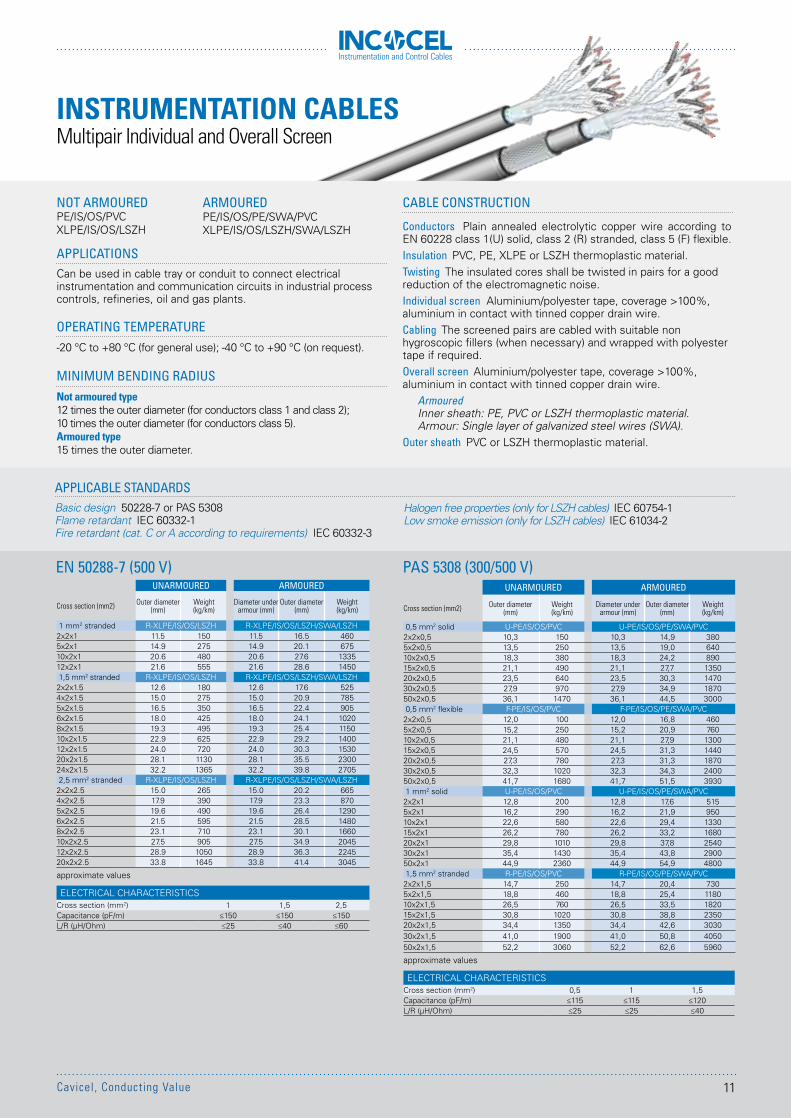
Multipair Individual and Overall Screen
APPLICATIONSCan be used in cable tray or conduit to connect electrical instrumentation and communication circuits in industrial process controls, refineries, oil and gas plants.
OPERATING TEMPERATURE-20 °C to +80 °C (for general use); -40 °C to +90 °C (on request).
MINIMUM BENDING RADIUSNot armoured type12 times the outer diameter (for conductors class 1 and class 2); 10 times the outer diameter (for conductors class 5).Armoured type15 times the outer diameter.
NOT ARMOUREDPE/IS/OS/PVCXLPE/IS/OS/LSZH
CABLE CONSTRUCTION
Conductors Plain annealed electrolytic copper wire according to EN 60228 class 1(U) solid, class 2 (R) stranded, class 5 (F) flexible.Insulation PVC, PE, XLPE or LSZH thermoplastic material.Twisting The insulated cores shall be twisted in pairs for a good reduction of the electromagnetic noise.Individual screen Aluminium/polyester tape, coverage >100%, aluminium in contact with tinned copper drain wire.Cabling The screened pairs are cabled with suitable non hygroscopic fillers (when necessary) and wrapped with polyester tape if required.Overall screen Aluminium/polyester tape, coverage >100%, aluminium in contact with tinned copper drain wire.
ArmouredInner sheath: PE, PVC or LSZH thermoplastic material.Armour: Single layer of galvanized steel wires (SWA).
Outer sheath PVC or LSZH thermoplastic material.
EN 50288-7 (500 V) PAS 5308 (300/500 V)
APPLICABLE STANDARDSBasic design 50228-7 or PAS 5308Flame retardant IEC 60332-1Fire retardant (cat. C or A according to requirements) IEC 60332-3
ARMOUREDPE/IS/OS/PE/SWA/PVCXLPE/IS/OS/LSZH/SWA/LSZH
UNARMOURED ARMOURED
Cross section (mm2) Outer diameter(mm)
Weight(kg/km)
Diameter under armour (mm)
Outer diameter(mm)
Weight(kg/km)
1 mm2 stranded R-XLPE/IS/OS/LSZH R-XLPE/IS/OS/LSZH/SWA/LSZH2x2x1 11.5 150 11.5 16.5 4605x2x1 14.9 275 14.9 20.1 67510x2x1 20.6 480 20.6 27.6 133512x2x1 21.6 555 21.6 28.6 14501,5 mm2 stranded R-XLPE/IS/OS/LSZH R-XLPE/IS/OS/LSZH/SWA/LSZH
2x2x1.5 12.6 180 12.6 17.6 5254x2x1.5 15.0 275 15.0 20.9 7855x2x1.5 16.5 350 16.5 22.4 9056x2x1.5 18.0 425 18.0 24.1 10208x2x1.5 19.3 495 19.3 25.4 115010x2x1.5 22.9 625 22.9 29.2 140012x2x1.5 24.0 720 24.0 30.3 153020x2x1.5 28.1 1130 28.1 35.5 230024x2x1.5 32.2 1365 32.2 39.8 27052,5 mm2 stranded R-XLPE/IS/OS/LSZH R-XLPE/IS/OS/LSZH/SWA/LSZH
2x2x2.5 15.0 265 15.0 20.2 6654x2x2.5 17.9 390 17.9 23.3 8705x2x2.5 19.6 490 19.6 26.4 12906x2x2.5 21.5 595 21.5 28.5 14808x2x2.5 23.1 710 23.1 30.1 166010x2x2.5 27.5 905 27.5 34.9 204512x2x2.5 28.9 1050 28.9 36.3 224520x2x2.5 33.8 1645 33.8 41.4 3045
approximate values
ELECTRICAL CHARACTERISTICSCross section (mm2) 1 1,5 2,5Capacitance (pF/m) ≤150 ≤150 ≤150L/R (µH/Ohm) ≤25 ≤40 ≤60
UNARMOURED ARMOURED
Cross section (mm2) Outer diameter(mm)
Weight(kg/km)
Diameter under armour (mm)
Outer diameter(mm)
Weight(kg/km)
0,5 mm2 solid U-PE/IS/OS/PVC U-PE/IS/OS/PE/SWA/PVC2x2x0,5 10,3 150 10,3 14,9 3805x2x0,5 13,5 250 13,5 19,0 64010x2x0,5 18,3 380 18,3 24,2 89015x2x0,5 21,1 490 21,1 27,7 135020x2x0,5 23,5 640 23,5 30,3 147030x2x0,5 27,9 970 27,9 34,9 187050x2x0,5 36,1 1470 36,1 44,5 30000,5 mm2 flexible F-PE/IS/OS/PVC F-PE/IS/OS/PE/SWA/PVC
2x2x0,5 12,0 100 12,0 16,8 4605x2x0,5 15,2 250 15,2 20,9 76010x2x0,5 21,1 480 21,1 27,9 130015x2x0,5 24,5 570 24,5 31,3 144020x2x0,5 27,3 780 27,3 31,3 187030x2x0,5 32,3 1020 32,3 34,3 240050x2x0,5 41,7 1680 41,7 51,5 39301 mm2 solid U-PE/IS/OS/PVC U-PE/IS/OS/PE/SWA/PVC2x2x1 12,8 200 12,8 17,6 5155x2x1 16,2 290 16,2 21,9 95010x2x1 22,6 580 22,6 29,4 133015x2x1 26,2 780 26,2 33,2 168020x2x1 29,8 1010 29,8 37,8 254030x2x1 35,4 1430 35,4 43,8 290050x2x1 44,9 2360 44,9 54,9 48001,5 mm2 stranded R-PE/IS/OS/PVC R-PE/IS/OS/PE/SWA/PVC
2x2x1,5 14,7 250 14,7 20,4 7305x2x1,5 18,8 460 18,8 25,4 118010x2x1,5 26,5 760 26,5 33,5 182015x2x1,5 30,8 1020 30,8 38,8 235020x2x1,5 34,4 1350 34,4 42,6 303030x2x1,5 41,0 1900 41,0 50,8 405050x2x1,5 52,2 3060 52,2 62,6 5960
approximate values
ELECTRICAL CHARACTERISTICSCross section (mm2) 0,5 1 1,5Capacitance (pF/m) ≤115 ≤115 ≤120L/R (µH/Ohm) ≤25 ≤25 ≤40
INSTRUMENTATION CABLES
Halogen free properties (only for LSZH cables) IEC 60754-1Low smoke emission (only for LSZH cables) IEC 61034-2
11Cavicel, Conducting Value
Instrumentation and Control Cables
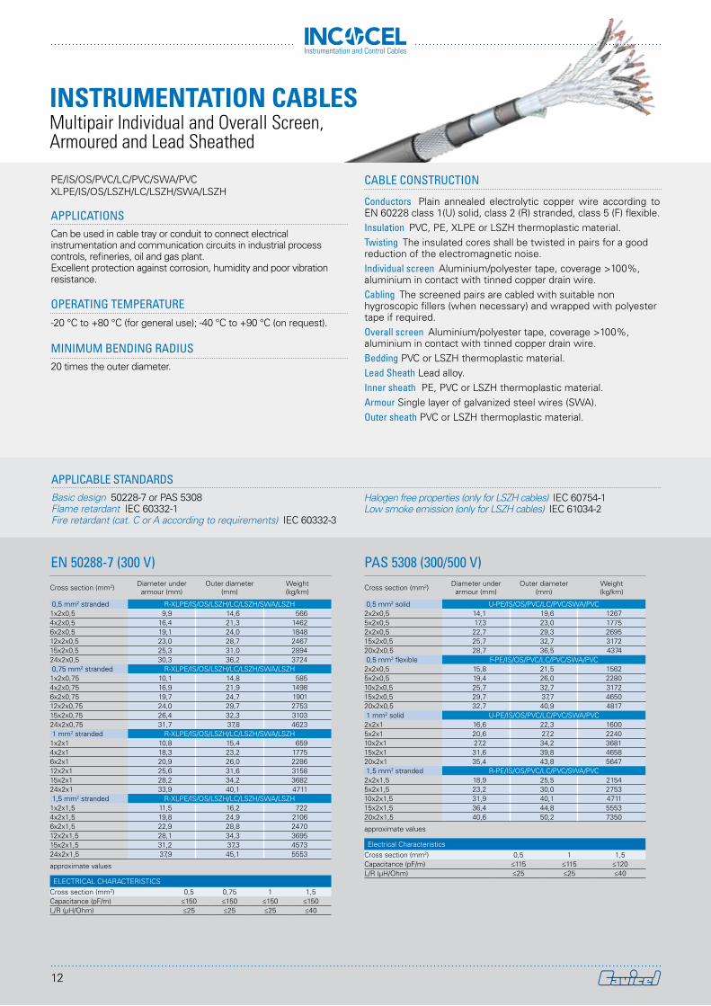
APPLICATIONSCan be used in cable tray or conduit to connect electrical instrumentation and communication circuits in industrial process controls, refineries, oil and gas plant.Excellent protection against corrosion, humidity and poor vibration resistance.
OPERATING TEMPERATURE-20 °C to +80 °C (for general use); -40 °C to +90 °C (on request).
MINIMUM BENDING RADIUS20 times the outer diameter.
PE/IS/OS/PVC/LC/PVC/SWA/PVCXLPE/IS/OS/LSZH/LC/LSZH/SWA/LSZH
CABLE CONSTRUCTION
Conductors Plain annealed electrolytic copper wire according to EN 60228 class 1(U) solid, class 2 (R) stranded, class 5 (F) flexible.Insulation PVC, PE, XLPE or LSZH thermoplastic material.Twisting The insulated cores shall be twisted in pairs for a good reduction of the electromagnetic noise.Individual screen Aluminium/polyester tape, coverage >100%, aluminium in contact with tinned copper drain wire.Cabling The screened pairs are cabled with suitable non hygroscopic fillers (when necessary) and wrapped with polyester tape if required.Overall screen Aluminium/polyester tape, coverage >100%, aluminium in contact with tinned copper drain wire. Bedding PVC or LSZH thermoplastic material. Lead Sheath Lead alloy.Inner sheath PE, PVC or LSZH thermoplastic material.Armour Single layer of galvanized steel wires (SWA). Outer sheath PVC or LSZH thermoplastic material.
EN 50288-7 (300 V) PAS 5308 (300/500 V)
APPLICABLE STANDARDSBasic design 50228-7 or PAS 5308Flame retardant IEC 60332-1Fire retardant (cat. C or A according to requirements) IEC 60332-3
Halogen free properties (only for LSZH cables) IEC 60754-1Low smoke emission (only for LSZH cables) IEC 61034-2
Cross section (mm2) Diameter under armour (mm)
Outer diameter(mm)
Weight(kg/km)
0,5 mm2 stranded R-XLPE/IS/OS/LSZH/LC/LSZH/SWA/LSZH1x2x0,5 9,9 14,6 5664x2x0,5 16,4 21,3 14626x2x0,5 19,1 24,0 184812x2x0,5 23,0 28,7 246715x2x0,5 25,3 31,0 289424x2x0,5 30,3 36,2 37240,75 mm2 stranded R-XLPE/IS/OS/LSZH/LC/LSZH/SWA/LSZH
1x2x0,75 10,1 14,8 5854x2x0,75 16,9 21,9 14986x2x0,75 19,7 24,7 190112x2x0,75 24,0 29,7 275315x2x0,75 26,4 32,3 310324x2x0,75 31,7 37,8 46231 mm2 stranded R-XLPE/IS/OS/LSZH/LC/LSZH/SWA/LSZH
1x2x1 10,8 15,4 6594x2x1 18,3 23,2 17756x2x1 20,9 26,0 228612x2x1 25,6 31,6 315815x2x1 28,2 34,2 368224x2x1 33,9 40,1 47111,5 mm2 stranded R-XLPE/IS/OS/LSZH/LC/LSZH/SWA/LSZH
1x2x1,5 11,5 16,2 7224x2x1,5 19,8 24,9 21066x2x1,5 22,9 28,8 247012x2x1,5 28,1 34,3 369515x2x1,5 31,2 37,3 457324x2x1,5 37,9 45,1 5553
approximate values
ELECTRICAL CHARACTERISTICSCross section (mm2) 0,5 0,75 1 1,5Capacitance (pF/m) ≤150 ≤150 ≤150 ≤150L/R (µH/Ohm) ≤25 ≤25 ≤25 ≤40
Cross section (mm2) Diameter under armour (mm)
Outer diameter(mm)
Weight(kg/km)
0,5 mm2 solid U-PE/IS/OS/PVC/LC/PVC/SWA/PVC2x2x0,5 14,1 19,6 12675x2x0,5 17,3 23,0 17752x2x0,5 22,7 29,3 269515x2x0,5 25,7 32,7 317220x2x0,5 28,7 36,5 43740,5 mm2 flexible F-PE/IS/OS/PVC/LC/PVC/SWA/PVC
2x2x0,5 15,8 21,5 15625x2x0,5 19,4 26,0 228010x2x0,5 25,7 32,7 317215x2x0,5 29,7 37,7 465020x2x0,5 32,7 40,9 48171 mm2 solid U-PE/IS/OS/PVC/LC/PVC/SWA/PVC
2x2x1 16,6 22,3 16005x2x1 20,6 27,2 224010x2x1 27,2 34,2 368115x2x1 31,6 39,8 465820x2x1 35,4 43,8 56471,5 mm2 stranded R-PE/IS/OS/PVC/LC/PVC/SWA/PVC
2x2x1,5 18,9 25,5 21545x2x1,5 23,2 30,0 275310x2x1,5 31,9 40,1 471115x2x1,5 36,4 44,8 555320x2x1,5 40,6 50,2 7350
approximate values
Electrical CharacteristicsCross section (mm2) 0,5 1 1,5Capacitance (pF/m) ≤115 ≤115 ≤120L/R (µH/Ohm) ≤25 ≤25 ≤40
INSTRUMENTATION CABLESMultipair Individual and Overall Screen, Armoured and Lead Sheathed
12
Instrumentation and Control Cables
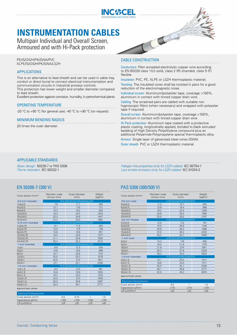
APPLICATIONSThis is an alternative to lead sheath and can be used in cable tray, conduit or direct burial to connect electrical instrumentation and communication circuits in industrial process controls. This protection has lower weight and smaller diameter compared to lead sheath.Excellent protection against corrosion, humidity, in petrochemical plants.
OPERATING TEMPERATURE-20 °C to +80 °C (for general use); -40 °C to +90 °C (on request).
MINIMUM BENDING RADIUS20 times the outer diameter.
PE/IS/OS/HIPK/SWA/PVC XLPE/IS/OS/HIPK/SWA/LSZH
EN 50288-7 (300 V) PAS 5308 (300/500 V)
APPLICABLE STANDARDSBasic design 50228-7 or PAS 5308Flame retardant IEC 60332-1
Cross section (mm2) Diameter under armour (mm)
Outer diameter(mm)
Weight(kg/km)
0,5 mm2 solid U-PE/IS/OS/HIPK/SWA/PVC2x2x0,5 11,3 15,7 6345x2x0,5 13,8 18,4 88810x2x0,5 18,2 23,4 134815x2x0,5 20,6 26,2 158620x2x0,5 23,0 29,2 21870,5 mm2 flexible F-PE/IS/OS/HIPK/SWA/PVC
2x2x0,5 12,6 17,2 7815x2x0,5 15,5 20,8 114010x2x0,5 20,6 26,2 158615x2x0,5 23,8 30,2 232520x2x0,5 26,2 32,7 24091 mm2 solid U-PE/IS/OS/HIPK/SWA/PVC
2x2x1 13,3 17,8 8005x2x1 16,5 21,8 112010x2x1 21,8 27,4 184115x2x1 25,3 31,8 232920x2x1 28,3 35,0 28241,5 mm2 stranded R-PE/IS/OS/HIPK/SWA/PVC
2x2x1,5 15,1 20,4 10775x2x1,5 18,6 24,0 137710x2x1,5 25,5 32,1 235615x2x1,5 29,1 35,8 277720x2x1,5 32,5 40,2 3675
approximate values
Electrical CharacteristicsCross section (mm2) 0,5 1 1,5Capacitance (pF/m) ≤115 ≤115 ≤120L/R (µH/Ohm) ≤25 ≤25 ≤40
Cross section (mm2) Diameter under armour (mm)
Outer diameter(mm)
Weight(kg/km)
0,5 mm2 stranded R-XLPE/IS/OS/HIPK/SWA/LSZH1x2x0,5 7,9 11,7 2834x2x0,5 13,1 17,0 7316x2x0,5 15,3 19,2 92412x2x0,5 18,4 23,0 123415x2x0,5 20,2 24,8 144724x2x0,5 24,2 29,0 18620,75 mm2 stranded R-XLPE/IS/OS/HIPK/SWA/LSZH
1x2x0,75 8,1 11,8 2934x2x0,75 13,5 17,5 7496x2x0,75 15,8 19,8 95112x2x0,75 19,2 23,8 137715x2x0,75 21,1 25,8 155224x2x0,75 25,4 30,2 23121 mm2 stranded R-XLPE/IS/OS/HIPK/SWA/LSZH
1x2x1 8,6 12,3 3304x2x1 14,6 18,6 8886x2x1 16,7 20,8 114312x2x1 20,5 25,3 157915x2x1 22,6 27,4 184124x2x1 27,1 32,1 23561,5 mm2 stranded R-XLPE/IS/OS/HIPK/SWA/LSZH
1x2x1,5 9,2 13,0 3614x2x1,5 15,8 19,9 10536x2x1,5 18,3 23,0 123512x2x1,5 22,5 27,4 184815x2x1,5 25,0 29,8 228724x2x1,5 30,3 36,1 2777
approximate values
Electrical CharacteristicsCross section (mm2) 0,5 0,75 1 1,5Capacitance (pF/m) ≤150 ≤150 ≤150 ≤150L/R (µH/Ohm) ≤25 ≤25 ≤25 ≤40
INSTRUMENTATION CABLESMultipair Individual and Overall Screen, Armoured and with Hi-Pack protection
CABLE CONSTRUCTION
Conductors Plain annealed electrolytic copper wire according to EN 60228 class 1(U) solid, class 2 (R) stranded, class 5 (F) flexible.Insulation PVC, PE, XLPE or LSZH thermoplastic material.Twisting The insulated cores shall be twisted in pairs for a good reduction of the electromagnetic noise.Individual screen Aluminium/polyester tape, coverage >100%, aluminium in contact with tinned copper drain wire.Cabling The screened pairs are cabled with suitable non hygroscopic fillers (when necessary) and wrapped with polyester tape if required.Overall screen Aluminium/polyester tape, coverage >100%, aluminium in contact with tinned copper drain wire.Hi-Pack protection Aluminium tape coated with a protective plastic coating, longitudinally applied, bonded to black extruded bedding of High Density Polyethylene compound plus an additional Polyamide-Polypropylene special thermoplastic alloy. Armour Single layer of galvanized steel wires (SWA). Outer sheath PVC or LSZH thermoplastic material.
Halogen free properties (only for LSZH cables) IEC 60754-1Low smoke emission (only for LSZH cables) IEC 61034-2
13Cavicel, Conducting Value
Instrumentation and Control Cables
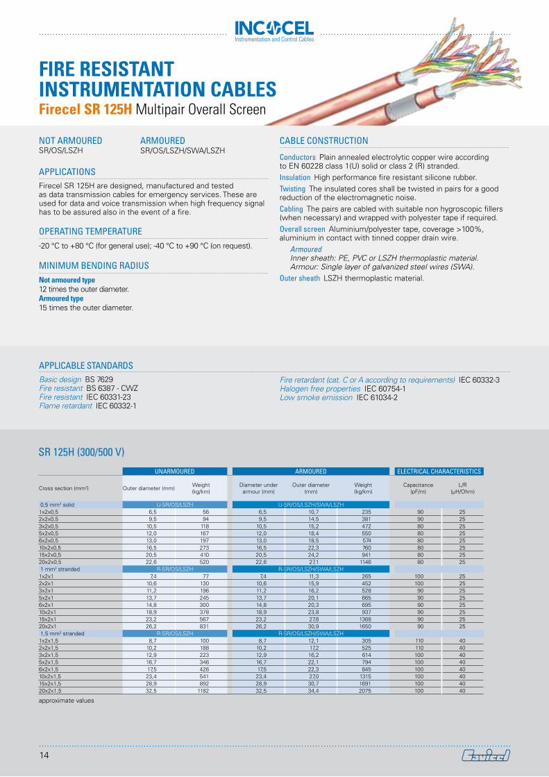
APPLICATIONSFirecel SR 125H are designed, manufactured and tested as data transmission cables for emergency services. These are used for data and voice transmission when high frequency signal has to be assured also in the event of a fire.
OPERATING TEMPERATURE-20 °C to +80 °C (for general use); -40 °C to +90 °C (on request).
MINIMUM BENDING RADIUSNot armoured type12 times the outer diameter.Armoured type15 times the outer diameter.
SR 125H (300/500 V)
APPLICABLE STANDARDSBasic design BS 7629Fire resistant BS 6387 - CWZFire resistant IEC 60331-23Flame retardant IEC 60332-1
CABLE CONSTRUCTION
Conductors Plain annealed electrolytic copper wire according to EN 60228 class 1(U) solid or class 2 (R) stranded.Insulation High performance fire resistant silicone rubber.Twisting The insulated cores shall be twisted in pairs for a good reduction of the electromagnetic noise.Cabling The pairs are cabled with suitable non hygroscopic fillers (when necessary) and wrapped with polyester tape if required.Overall screen Aluminium/polyester tape, coverage >100%, aluminium in contact with tinned copper drain wire.
Armoured Inner sheath: PE, PVC or LSZH thermoplastic material.Armour: Single layer of galvanized steel wires (SWA).
Outer sheath LSZH thermoplastic material.
Fire retardant (cat. C or A according to requirements) IEC 60332-3Halogen free properties IEC 60754-1Low smoke emission IEC 61034-2
UNARMOURED ARMOURED ELECTRICAL CHARACTERISTICS
Cross section (mm2) Outer diameter (mm) Weight(kg/km)
Diameter under armour (mm)
Outer diameter(mm)
Weight(kg/km)
Capacitance(pF/m)
L/R(µH/Ohm)
0,5 mm2 solid U-SR/OS/LSZH U-SR/OS/LSZH/SWA/LSZH1x2x0,5 6,5 56 6,5 10,7 235 90 252x2x0,5 9,5 94 9,5 14,5 381 90 253x2x0,5 10,5 118 10,5 15,2 472 80 255x2x0,5 12,0 167 12,0 18,4 550 80 256x2x0,5 13,0 197 13,0 18,5 574 80 2510x2x0,5 16,5 273 16,5 22,3 760 80 2515x2x0,5 20,5 410 20,5 24,2 941 80 2520x2x0,5 22,6 520 22,6 27,1 1146 80 251 mm2 stranded R-SR/OS/LSZH R-SR/OS/LSZH/SWA/LSZH
1x2x1 7,4 77 7,4 11,3 265 100 252x2x1 10,6 130 10,6 15,9 452 100 253x2x1 11,2 196 11,2 16,2 528 90 255x2x1 13,7 245 13,7 20,1 665 90 256x2x1 14,8 300 14,8 20,3 695 90 2510x2x1 18,9 378 18,9 23,8 937 90 2515x2x1 23,2 567 23,2 27,8 1368 90 2520x2x1 26,2 831 26,2 30,9 1650 90 251,5 mm2 stranded R-SR/OS/LSZH R-SR/OS/LSZH/SWA/LSZH
1x2x1,5 8,7 100 8,7 12,1 305 110 402x2x1,5 10,2 188 10,2 17,2 525 110 403x2x1,5 12,9 223 12,9 16,2 614 100 405x2x1,5 16,7 346 16,7 22,1 794 100 406x2x1,5 17,5 426 17,5 22,3 845 100 4010x2x1,5 23,4 541 23,4 27,0 1315 100 4015x2x1,5 28,9 892 28,9 30,7 1691 100 4020x2x1,5 32,5 1182 32,5 34,4 2075 100 40
approximate values
NOT ARMOUREDSR/OS/LSZH
ARMOUREDSR/OS/LSZH/SWA/LSZH
FIRE RESISTANT INSTRUMENTATION CABLESFirecel SR 125H Multipair Overall Screen
14
Instrumentation and Control Cables
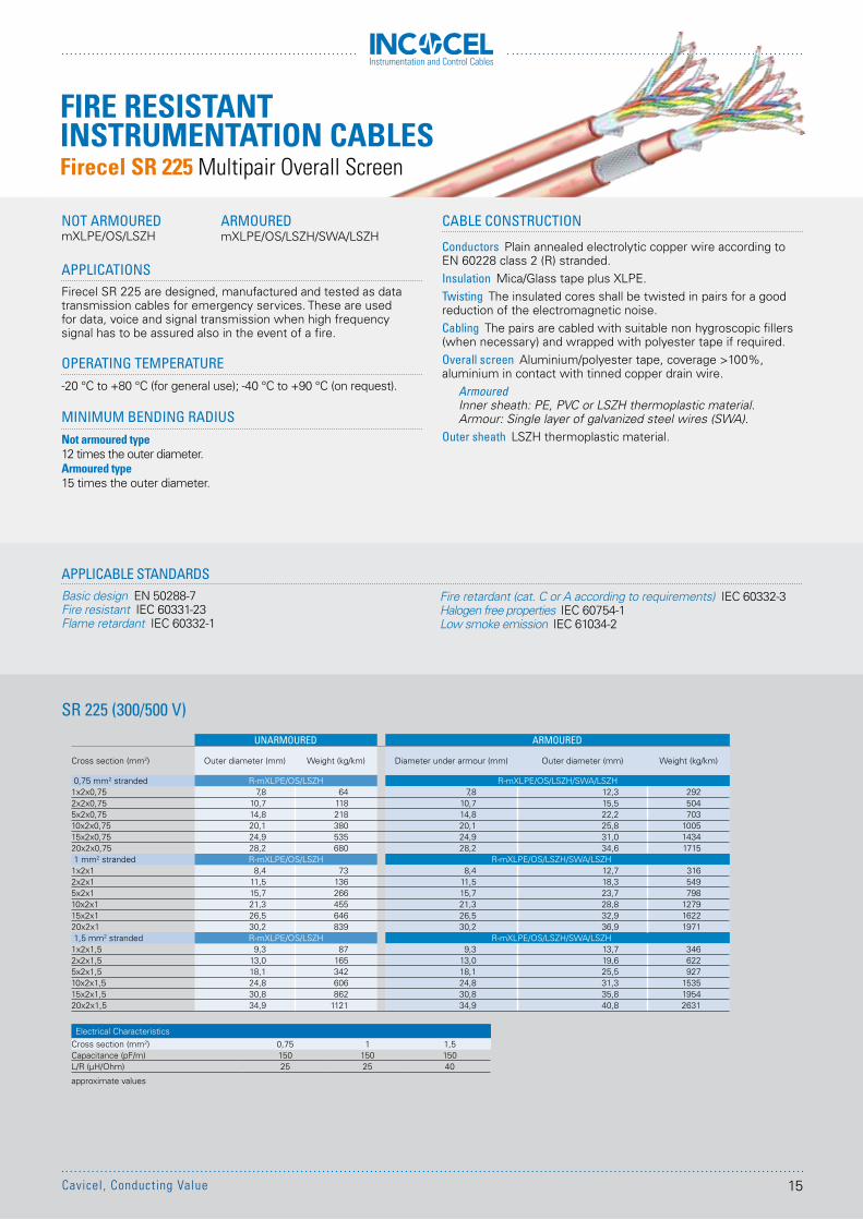
APPLICATIONSFirecel SR 225 are designed, manufactured and tested as data transmission cables for emergency services. These are used for data, voice and signal transmission when high frequency signal has to be assured also in the event of a fire.
OPERATING TEMPERATURE-20 °C to +80 °C (for general use); -40 °C to +90 °C (on request).
MINIMUM BENDING RADIUSNot armoured type12 times the outer diameter.Armoured type15 times the outer diameter.
CABLE CONSTRUCTION
Conductors Plain annealed electrolytic copper wire according to EN 60228 class 2 (R) stranded.Insulation Mica/Glass tape plus XLPE.Twisting The insulated cores shall be twisted in pairs for a good reduction of the electromagnetic noise.Cabling The pairs are cabled with suitable non hygroscopic fillers (when necessary) and wrapped with polyester tape if required.Overall screen Aluminium/polyester tape, coverage >100%, aluminium in contact with tinned copper drain wire.
Armoured Inner sheath: PE, PVC or LSZH thermoplastic material.Armour: Single layer of galvanized steel wires (SWA).
Outer sheath LSZH thermoplastic material.
SR 225 (300/500 V)
APPLICABLE STANDARDSBasic design EN 50288-7Fire resistant IEC 60331-23Flame retardant IEC 60332-1
Fire retardant (cat. C or A according to requirements) IEC 60332-3Halogen free properties IEC 60754-1Low smoke emission IEC 61034-2
NOT ARMOUREDmXLPE/OS/LSZH
ARMOUREDmXLPE/OS/LSZH/SWA/LSZH
UNARMOURED ARMOURED
Cross section (mm2) Outer diameter (mm) Weight (kg/km) Diameter under armour (mm) Outer diameter (mm) Weight (kg/km)
0,75 mm2 stranded R-mXLPE/OS/LSZH R-mXLPE/OS/LSZH/SWA/LSZH1x2x0,75 7,8 64 7,8 12,3 2922x2x0,75 10,7 118 10,7 15,5 5045x2x0,75 14,8 218 14,8 22,2 70310x2x0,75 20,1 380 20,1 25,8 100515x2x0,75 24,9 535 24,9 31,0 143420x2x0,75 28,2 680 28,2 34,6 17151 mm2 stranded R-mXLPE/OS/LSZH R-mXLPE/OS/LSZH/SWA/LSZH
1x2x1 8,4 73 8,4 12,7 3162x2x1 11,5 136 11,5 18,3 5495x2x1 15,7 266 15,7 23,7 79810x2x1 21,3 455 21,3 28,8 127915x2x1 26,5 646 26,5 32,9 162220x2x1 30,2 839 30,2 36,9 19711,5 mm2 stranded R-mXLPE/OS/LSZH R-mXLPE/OS/LSZH/SWA/LSZH
1x2x1,5 9,3 87 9,3 13,7 3462x2x1,5 13,0 165 13,0 19,6 6225x2x1,5 18,1 342 18,1 25,5 92710x2x1,5 24,8 606 24,8 31,3 153515x2x1,5 30,8 862 30,8 35,8 195420x2x1,5 34,9 1121 34,9 40,8 2631
Electrical CharacteristicsCross section (mm2) 0,75 1 1,5Capacitance (pF/m) 150 150 150L/R (µH/Ohm) 25 25 40
approximate values
FIRE RESISTANT INSTRUMENTATION CABLESFirecel SR 225 Multipair Overall Screen
15Cavicel, Conducting Value
Instrumentation and Control Cables
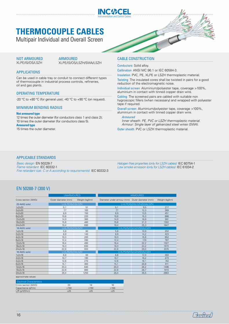
APPLICATIONSCan be used in cable tray or conduit to connect different types of thermocouple in industrial process controls, refineries, oil and gas plants.
OPERATING TEMPERATURE-20 °C to +80 °C (for general use); -40 °C to +90 °C (on request).
MINIMUM BENDING RADIUSNot armoured type12 times the outer diameter (for conductors class 1 and class 2); 10 times the outer diameter (for conductors class 5).Armoured type15 times the outer diameter.
CABLE CONSTRUCTION
Conductors Solid alloy.Calibration ANSI MC 96.1 or IEC 60584-3.Insulation PVC, PE, XLPE or LSZH thermoplastic material.Twisting The insulated cores shall be twisted in pairs for a good reduction of the electromagnetic noise.Individual screen Aluminium/polyester tape, coverage >100%, aluminium in contact with tinned copper drain wire.Cabling The screened pairs are cabled with suitable non hygroscopic fillers (when necessary) and wrapped with polyester tape if required.Overall screen Aluminium/polyester tape, coverage >100%, aluminium in contact with tinned copper drain wire.
ArmouredInner sheath: PE, PVC or LSZH thermoplastic material.Armour: Single layer of galvanized steel wires (SWA).
Outer sheath PVC or LSZH thermoplastic material.
EN 50288-7 (300 V)
APPLICABLE STANDARDSBasic design EN 50228-7Flame retardant IEC 60332-1Fire retardant (cat. C or A according to requirements) IEC 60332-3
Halogen free properties (only for LSZH cables) IEC 60754-1Low smoke emission (only for LSZH cables) IEC 61034-2
UNARMOURED ARMOURED
Cross section (AWG) Outer diameter (mm) Weight (kg/km) Diameter under armour (mm) Outer diameter (mm) Weight (kg/km)
20 AWG solid U-XLPE/IS/OS/LSZH U-XLPE/IS/OS/LSZH/SWA/LSZH1x2x20 5,1 51 5,1 9,5 2172x2x20 7,7 100 7,7 12,3 3694x2x20 8,9 150 8,9 13,5 4516x2x20 10,6 220 10,6 15,3 66612x2x20 14,0 360 14,0 18,9 90116x2x20 15,6 480 15,6 21,3 130224x2x20 19,4 690 19,4 25,3 164718 AWG solid U-XLPE/IS/OS/LSZH U-XLPE/IS/OS/LSZH/SWA/LSZH
1x2x18 5,8 60 5,8 10,9 2522x2x18 8,9 140 8,9 14,2 4234x2x18 10,3 200 10,3 15,8 6526x2x18 12,4 280 12,4 17,9 78712x2x18 16,4 490 16,4 22,2 132716x2x18 18,3 630 18,3 24,2 157224x2x18 22,8 930 22,8 29,0 207416 AWG solid U-XLPE/IS/OS/LSZH U-XLPE/IS/OS/LSZH/SWA/LSZH
1x2x16 6,8 63 6,8 12,0 2832x2x16 10,7 180 10,7 16,2 4734x2x16 12,6 270 12,6 18,1 7426x2x16 15,1 360 15,1 20,8 91112x2x16 20,3 640 20,3 26,2 149616x2x16 22,6 860 22,6 28,7 191524x2x16 28,4 1250 28,4 35,5 2663
approximate values
Electrical CharacteristicsCross section (AWG) 20 18 16Capacitance (pF/m) ≤150 ≤150 ≤150L/R (µH/Ohm) ≤25 ≤25 ≤25
NOT ARMOUREDXLPE/IS/OS/LSZH
ARMOUREDXLPE/IS/OS/LSZH/SWA/LSZH
THERMOCOUPLE CABLESMultipair Individual and Overall Screen
16
Instrumentation and Control Cables
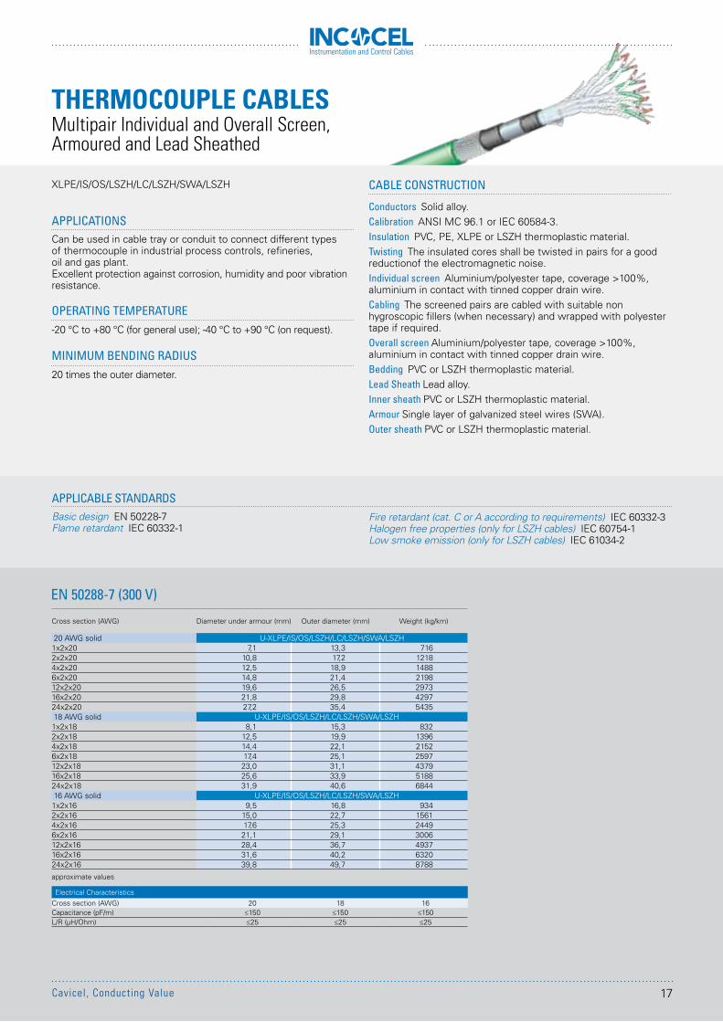
APPLICATIONSCan be used in cable tray or conduit to connect different types of thermocouple in industrial process controls, refineries, oil and gas plant.Excellent protection against corrosion, humidity and poor vibration resistance.
OPERATING TEMPERATURE-20 °C to +80 °C (for general use); -40 °C to +90 °C (on request).
MINIMUM BENDING RADIUS20 times the outer diameter.
XLPE/IS/OS/LSZH/LC/LSZH/SWA/LSZH
EN 50288-7 (300 V)
APPLICABLE STANDARDSBasic design EN 50228-7Flame retardant IEC 60332-1
Cross section (AWG) Diameter under armour (mm) Outer diameter (mm) Weight (kg/km)
20 AWG solid U-XLPE/IS/OS/LSZH/LC/LSZH/SWA/LSZH1x2x20 7,1 13,3 7162x2x20 10,8 17,2 12184x2x20 12,5 18,9 14886x2x20 14,8 21,4 219812x2x20 19,6 26,5 297316x2x20 21,8 29,8 429724x2x20 27,2 35,4 543518 AWG solid U-XLPE/IS/OS/LSZH/LC/LSZH/SWA/LSZH1x2x18 8,1 15,3 8322x2x18 12,5 19,9 13964x2x18 14,4 22,1 21526x2x18 17,4 25,1 259712x2x18 23,0 31,1 437916x2x18 25,6 33,9 518824x2x18 31,9 40,6 684416 AWG solid U-XLPE/IS/OS/LSZH/LC/LSZH/SWA/LSZH1x2x16 9,5 16,8 9342x2x16 15,0 22,7 15614x2x16 17,6 25,3 24496x2x16 21,1 29,1 300612x2x16 28,4 36,7 493716x2x16 31,6 40,2 632024x2x16 39,8 49,7 8788
approximate values
Electrical CharacteristicsCross section (AWG) 20 18 16Capacitance (pF/m) ≤150 ≤150 ≤150L/R (µH/Ohm) ≤25 ≤25 ≤25
CABLE CONSTRUCTION
Conductors Solid alloy.Calibration ANSI MC 96.1 or IEC 60584-3.Insulation PVC, PE, XLPE or LSZH thermoplastic material.Twisting The insulated cores shall be twisted in pairs for a good reductionof the electromagnetic noise.Individual screen Aluminium/polyester tape, coverage >100%, aluminium in contact with tinned copper drain wire.Cabling The screened pairs are cabled with suitable non hygroscopic fillers (when necessary) and wrapped with polyester tape if required.Overall screen Aluminium/polyester tape, coverage >100%, aluminium in contact with tinned copper drain wire. Bedding PVC or LSZH thermoplastic material. Lead Sheath Lead alloy.Inner sheath PVC or LSZH thermoplastic material.Armour Single layer of galvanized steel wires (SWA). Outer sheath PVC or LSZH thermoplastic material.
Fire retardant (cat. C or A according to requirements) IEC 60332-3Halogen free properties (only for LSZH cables) IEC 60754-1Low smoke emission (only for LSZH cables) IEC 61034-2
THERMOCOUPLE CABLESMultipair Individual and Overall Screen, Armoured and Lead Sheathed
17Cavicel, Conducting Value
Instrumentation and Control Cables
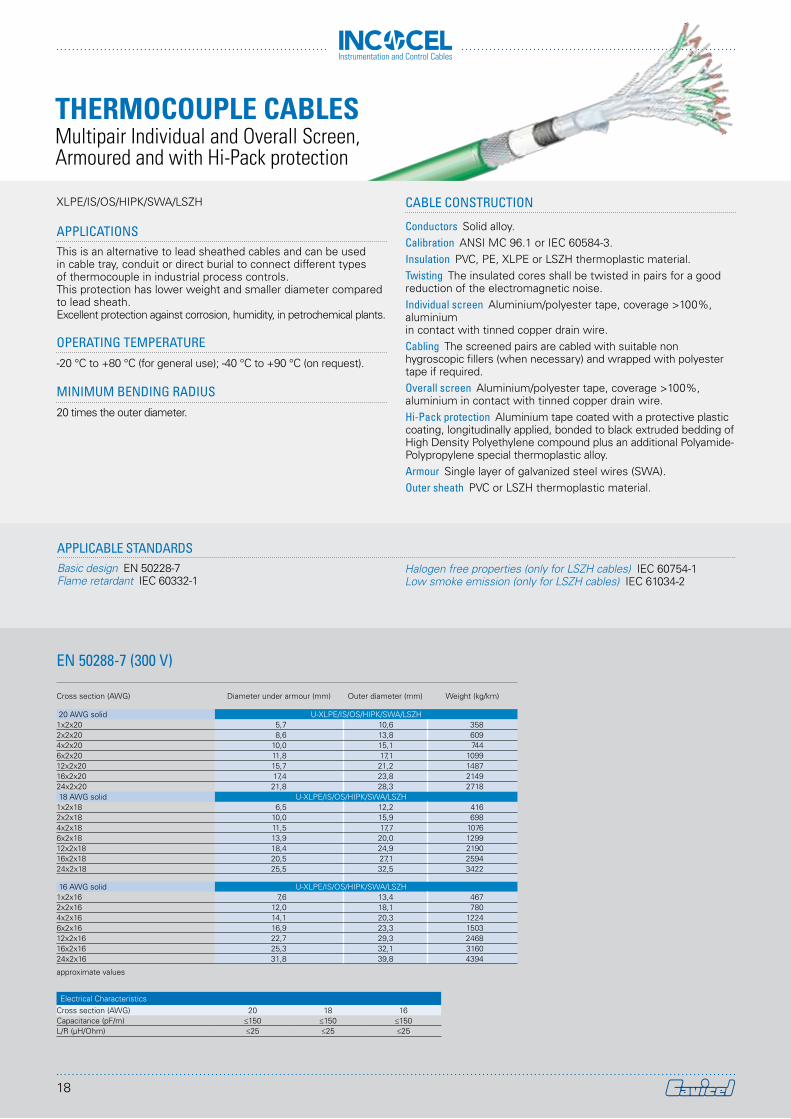
APPLICATIONSThis is an alternative to lead sheathed cables and can be used in cable tray, conduit or direct burial to connect different types of thermocouple in industrial process controls. This protection has lower weight and smaller diameter compared to lead sheath.Excellent protection against corrosion, humidity, in petrochemical plants.
OPERATING TEMPERATURE-20 °C to +80 °C (for general use); -40 °C to +90 °C (on request).
MINIMUM BENDING RADIUS20 times the outer diameter.
CABLE CONSTRUCTION
Conductors Solid alloy.Calibration ANSI MC 96.1 or IEC 60584-3.Insulation PVC, PE, XLPE or LSZH thermoplastic material.Twisting The insulated cores shall be twisted in pairs for a good reduction of the electromagnetic noise.Individual screen Aluminium/polyester tape, coverage >100%, aluminium in contact with tinned copper drain wire.Cabling The screened pairs are cabled with suitable non hygroscopic fillers (when necessary) and wrapped with polyester tape if required.Overall screen Aluminium/polyester tape, coverage >100%, aluminium in contact with tinned copper drain wire. Hi-Pack protection Aluminium tape coated with a protective plastic coating, longitudinally applied, bonded to black extruded bedding of High Density Polyethylene compound plus an additional Polyamide-Polypropylene special thermoplastic alloy. Armour Single layer of galvanized steel wires (SWA).Outer sheath PVC or LSZH thermoplastic material.
EN 50288-7 (300 V)
APPLICABLE STANDARDSBasic design EN 50228-7Flame retardant IEC 60332-1
Halogen free properties (only for LSZH cables) IEC 60754-1Low smoke emission (only for LSZH cables) IEC 61034-2
XLPE/IS/OS/HIPK/SWA/LSZH
Cross section (AWG) Diameter under armour (mm) Outer diameter (mm) Weight (kg/km)
20 AWG solid U-XLPE/IS/OS/HIPK/SWA/LSZH1x2x20 5,7 10,6 3582x2x20 8,6 13,8 6094x2x20 10,0 15,1 7446x2x20 11,8 17,1 109912x2x20 15,7 21,2 148716x2x20 17,4 23,8 214924x2x20 21,8 28,3 271818 AWG solid U-XLPE/IS/OS/HIPK/SWA/LSZH
1x2x18 6,5 12,2 4162x2x18 10,0 15,9 6984x2x18 11,5 17,7 10766x2x18 13,9 20,0 129912x2x18 18,4 24,9 219016x2x18 20,5 27,1 259424x2x18 25,5 32,5 3422
16 AWG solid U-XLPE/IS/OS/HIPK/SWA/LSZH1x2x16 7,6 13,4 4672x2x16 12,0 18,1 7804x2x16 14,1 20,3 12246x2x16 16,9 23,3 150312x2x16 22,7 29,3 246816x2x16 25,3 32,1 316024x2x16 31,8 39,8 4394
approximate values
Electrical CharacteristicsCross section (AWG) 20 18 16Capacitance (pF/m) ≤150 ≤150 ≤150L/R (µH/Ohm) ≤25 ≤25 ≤25
THERMOCOUPLE CABLESMultipair Individual and Overall Screen, Armoured and with Hi-Pack protection
18
Instrumentation and Control Cables
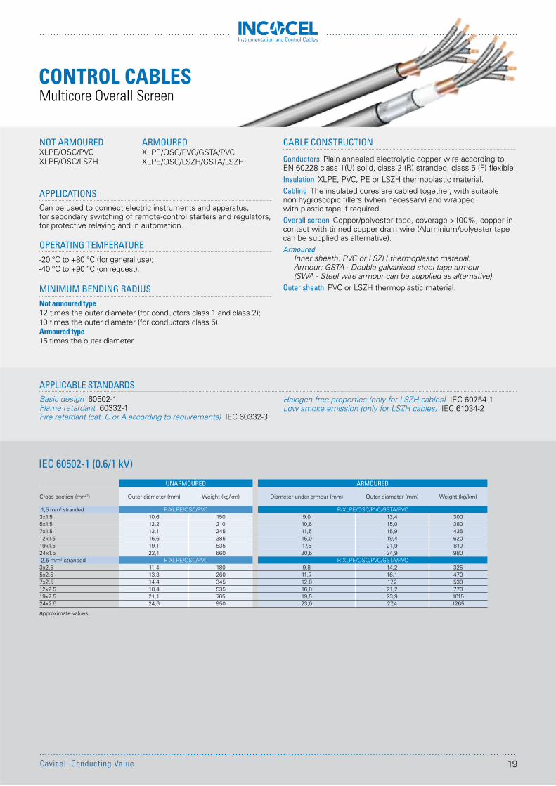
APPLICATIONSCan be used to connect electric instruments and apparatus, for secondary switching of remote-control starters and regulators, for protective relaying and in automation.
OPERATING TEMPERATURE-20 °C to +80 °C (for general use);-40 °C to +90 °C (on request).
MINIMUM BENDING RADIUSNot armoured type12 times the outer diameter (for conductors class 1 and class 2); 10 times the outer diameter (for conductors class 5).Armoured type15 times the outer diameter.
IEC 60502-1 (0.6/1 kV)
APPLICABLE STANDARDSBasic design 60502-1Flame retardant 60332-1Fire retardant (cat. C or A according to requirements) IEC 60332-3
CABLE CONSTRUCTION
Conductors Plain annealed electrolytic copper wire according to EN 60228 class 1(U) solid, class 2 (R) stranded, class 5 (F) flexible.Insulation XLPE, PVC, PE or LSZH thermoplastic material.Cabling The insulated cores are cabled together, with suitable non hygroscopic fillers (when necessary) and wrapped with plastic tape if required.Overall screen Copper/polyester tape, coverage >100%, copper in contact with tinned copper drain wire (Aluminium/polyester tape can be supplied as alternative). Armoured
Inner sheath: PVC or LSZH thermoplastic material.Armour: GSTA - Double galvanized steel tape armour (SWA - Steel wire armour can be supplied as alternative).
Outer sheath PVC or LSZH thermoplastic material.
Halogen free properties (only for LSZH cables) IEC 60754-1Low smoke emission (only for LSZH cables) IEC 61034-2
NOT ARMOUREDXLPE/OSC/PVCXLPE/OSC/LSZH
ARMOUREDXLPE/OSC/PVC/GSTA/PVCXLPE/OSC/LSZH/GSTA/LSZH
UNARMOURED ARMOURED
Cross section (mm2) Outer diameter (mm) Weight (kg/km) Diameter under armour (mm) Outer diameter (mm) Weight (kg/km)
1,5 mm2 stranded R-XLPE/OSC/PVC R-XLPE/OSC/PVC/GSTA/PVC3x1.5 10,6 150 9,0 13,4 3005x1.5 12,2 210 10,6 15,0 3807x1.5 13,1 245 11,5 15,9 43512x1.5 16,6 385 15,0 19,4 62019x1.5 19,1 535 17,5 21,9 81024x1.5 22,1 660 20,5 24,9 9802,5 mm2 stranded R-XLPE/OSC/PVC R-XLPE/OSC/PVC/GSTA/PVC
3x2.5 11,4 180 9,8 14,2 3255x2.5 13,3 260 11,7 16,1 4707x2.5 14,4 345 12,8 17,2 53012x2.5 18,4 535 16,8 21,2 77019x2.5 21,1 765 19,5 23,9 101524x2.5 24,6 950 23,0 27,4 1265
approximate values
Multicore Overall ScreenCONTROL CABLES
19Cavicel, Conducting Value
Instrumentation and Control Cables
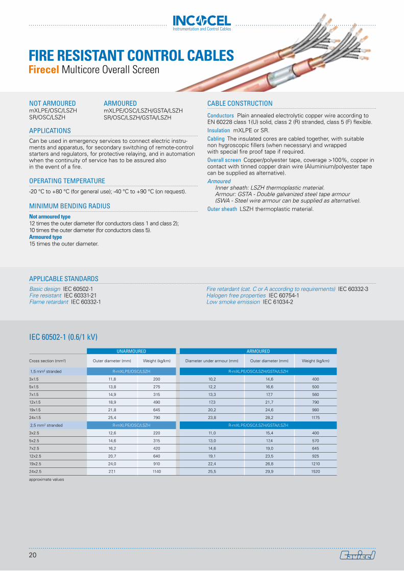
APPLICATIONSCan be used in emergency services to connect electric instru-ments and apparatus, for secondary switching of remote-control starters and regulators, for protective relaying, and in automation when the continuity of service has to be assured also in the event of a fire.
OPERATING TEMPERATURE-20 °C to +80 °C (for general use); -40 °C to +90 °C (on request).
MINIMUM BENDING RADIUSNot armoured type12 times the outer diameter (for conductors class 1 and class 2); 10 times the outer diameter (for conductors class 5).Armoured type15 times the outer diameter.
CABLE CONSTRUCTION
Conductors Plain annealed electrolytic copper wire according to EN 60228 class 1(U) solid, class 2 (R) stranded, class 5 (F) flexible.Insulation mXLPE or SR.Cabling The insulated cores are cabled together, with suitable non hygroscopic fillers (when necessary) and wrapped with special fire proof tape if required.Overall screen Copper/polyester tape, coverage >100%, copper in contact with tinned copper drain wire (Aluminium/polyester tape can be supplied as alternative). Armoured
Inner sheath: LSZH thermoplastic material.Armour: GSTA - Double galvanized steel tape armour(SWA - Steel wire armour can be supplied as alternative).
Outer sheath LSZH thermoplastic material.
IEC 60502-1 (0.6/1 kV)
APPLICABLE STANDARDSBasic design IEC 60502-1Fire resistant IEC 60331-21Flame retardant IEC 60332-1
Fire retardant (cat. C or A according to requirements) IEC 60332-3Halogen free properties IEC 60754-1Low smoke emission IEC 61034-2
NOT ARMOUREDmXLPE/OSC/LSZHSR/OSC/LSZH
ARMOUREDmXLPE/OSC/LSZH/GSTA/LSZHSR/OSC/LSZH/GSTA/LSZH
UNARMOURED ARMOURED
Cross section (mm2) Outer diameter (mm) Weight (kg/km) Diameter under armour (mm) Outer diameter (mm) Weight (kg/km)
1,5 mm2 stranded R-mXLPE/OSC/LSZH R-mXLPE/OSC/LSZH/GSTA/LSZH
3x1.5 11,8 200 10,2 14,6 400
5x1.5 13,8 275 12,2 16,6 500
7x1.5 14,9 315 13,3 17,7 560
12x1.5 18,9 490 17,3 21,7 790
19x1.5 21,8 645 20,2 24,6 980
24x1.5 25,4 790 23,8 28,2 1175
2,5 mm2 stranded R-mXLPE/OSC/LSZH R-mXLPE/OSC/LSZH/GSTA/LSZH
3x2.5 12,6 220 11,0 15,4 400
5x2.5 14,6 315 13,0 17,4 570
7x2.5 16,2 420 14,6 19,0 645
12x2.5 20,7 640 19,1 23,5 925
19x2.5 24,0 910 22,4 26,8 1210
24x2.5 27,1 1140 25,5 29,9 1520
approximate values
FIRE RESISTANT CONTROL CABLESFirecel Multicore Overall Screen
20
Instrumentation and Control Cables
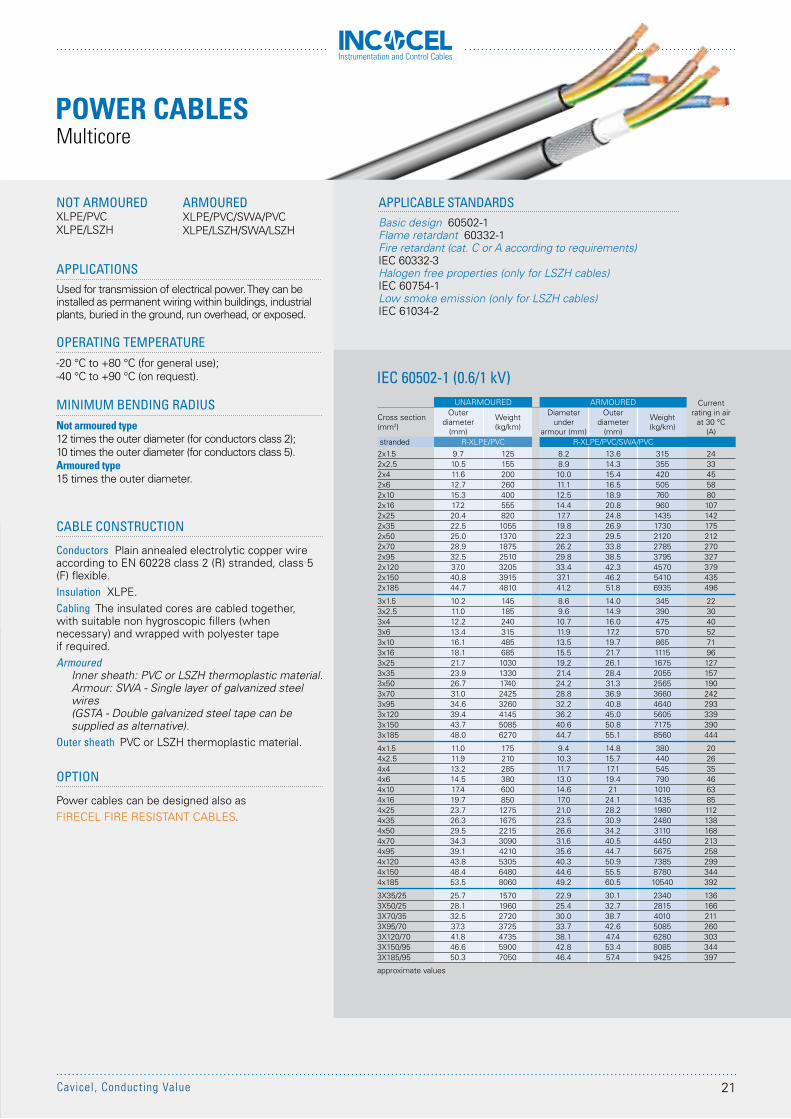
APPLICATIONSUsed for transmission of electrical power. They can be installed as permanent wiring within buildings, industrial plants, buried in the ground, run overhead, or exposed.
OPERATING TEMPERATURE-20 °C to +80 °C (for general use);-40 °C to +90 °C (on request).
MINIMUM BENDING RADIUSNot armoured type12 times the outer diameter (for conductors class 2); 10 times the outer diameter (for conductors class 5).Armoured type15 times the outer diameter.
IEC 60502-1 (0.6/1 kV)
APPLICABLE STANDARDSBasic design 60502-1Flame retardant 60332-1Fire retardant (cat. C or A according to requirements) IEC 60332-3Halogen free properties (only for LSZH cables) IEC 60754-1Low smoke emission (only for LSZH cables) IEC 61034-2
CABLE CONSTRUCTION
Conductors Plain annealed electrolytic copper wire according to EN 60228 class 2 (R) stranded, class 5 (F) flexible.Insulation XLPE.Cabling The insulated cores are cabled together, with suitable non hygroscopic fillers (when necessary) and wrapped with polyester tape if required.Armoured
Inner sheath: PVC or LSZH thermoplastic material.Armour: SWA - Single layer of galvanized steel wires(GSTA - Double galvanized steel tape can be supplied as alternative).
Outer sheath PVC or LSZH thermoplastic material.
OPTION
Power cables can be designed also asFIRECEL FIRE RESISTANT CABLES.
NOT ARMOUREDXLPE/PVCXLPE/LSZH
ARMOUREDXLPE/PVC/SWA/PVCXLPE/LSZH/SWA/LSZH
UNARMOURED ARMOURED Current rating in air
at 30 °C(A)
Cross section(mm2)
Outer diameter
(mm)
Weight(kg/km)
Diameter under
armour (mm)
Outer diameter
(mm)
Weight(kg/km)
stranded R-XLPE/PVC R-XLPE/PVC/SWA/PVC2x1.5 9.7 125 8.2 13.6 315 242x2.5 10.5 155 8.9 14.3 355 332x4 11.6 200 10.0 15.4 420 452x6 12.7 260 11.1 16.5 505 582x10 15.3 400 12.5 18.9 760 802x16 17.2 555 14.4 20.8 960 1072x25 20.4 820 17.7 24.8 1435 1422x35 22.5 1055 19.8 26.9 1730 1752x50 25.0 1370 22.3 29.5 2120 2122x70 28.9 1875 26.2 33.8 2785 2702x95 32.5 2510 29.8 38.5 3795 3272x120 37.0 3205 33.4 42.3 4570 3792x150 40.8 3915 37.1 46.2 5410 4352x185 44.7 4810 41.2 51.8 6935 496
3x1.5 10.2 145 8.6 14.0 345 223x2.5 11.0 185 9.6 14.9 390 303x4 12.2 240 10.7 16.0 475 403x6 13.4 315 11.9 17.2 570 523x10 16.1 485 13.5 19.7 865 713x16 18.1 685 15.5 21.7 1115 963x25 21.7 1030 19.2 26.1 1675 1273x35 23.9 1330 21.4 28.4 2055 1573x50 26.7 1740 24.2 31.3 2565 1903x70 31.0 2425 28.8 36.9 3660 2423x95 34.6 3260 32.2 40.8 4640 2933x120 39.4 4145 36.2 45.0 5605 3393x150 43.7 5085 40.6 50.8 7175 3903x185 48.0 6270 44.7 55.1 8560 444
4x1.5 11.0 175 9.4 14.8 380 204x2.5 11.9 210 10.3 15.7 440 264x4 13.2 285 11.7 17.1 545 354x6 14.5 380 13.0 19.4 790 464x10 17.4 600 14.6 21 1010 634x16 19.7 850 17.0 24.1 1435 854x25 23.7 1275 21.0 28.2 1980 1124x35 26.3 1675 23.5 30.9 2480 1384x50 29.5 2215 26.6 34.2 3110 1684x70 34.3 3090 31.6 40.5 4450 2134x95 39.1 4210 35.6 44.7 5675 2584x120 43.8 5305 40.3 50.9 7385 2994x150 48.4 6480 44.6 55.5 8780 3444x185 53.5 8060 49.2 60.5 10540 392
3X35/25 25.7 1570 22.9 30.1 2340 1363X50/25 28.1 1960 25.4 32.7 2815 1663X70/35 32.5 2720 30.0 38.7 4010 2113X95/70 37.3 3725 33.7 42.6 5085 2603X120/70 41.8 4735 38.1 47.4 6280 3033X150/95 46.6 5900 42.8 53.4 8085 3443X185/95 50.3 7050 46.4 57.4 9425 397
approximate values
POWER CABLESMulticore
21Cavicel, Conducting Value
Instrumentation and Control Cables
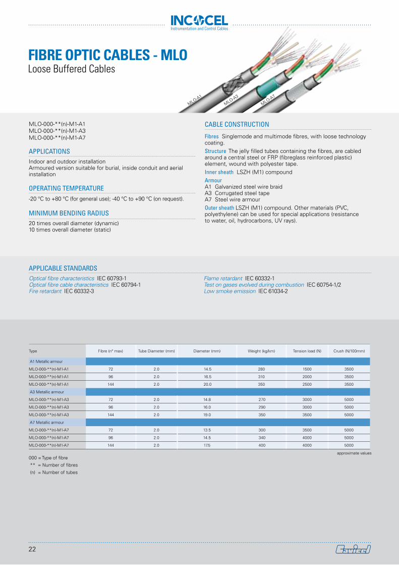
FIBRE OPTIC CABLES - MLO
APPLICATIONSIndoor and outdoor installationArmoured version suitable for burial, inside conduit and aerial installation
OPERATING TEMPERATURE-20 °C to +80 °C (for general use); -40 °C to +90 °C (on request).
MINIMUM BENDING RADIUS20 times overall diameter (dynamic)10 times overall diameter (static)
CABLE CONSTRUCTION
Fibres Singlemode and multimode fibres, with loose technology coating.Structure The jelly filled tubes containing the fibres, are cabled around a central steel or FRP (fibreglass reinforced plastic) element, wound with polyester tape.Inner sheath LSZH (M1) compoundArmourA1 Galvanized steel wire braidA3 Corrugated steel tapeA7 Steel wire armourOuter sheath LSZH (M1) compound. Other materials (PVC, polyethylene) can be used for special applications (resistance to water, oil, hydrocarbons, UV rays).
APPLICABLE STANDARDSOptical fibre characteristics IEC 60793-1 Optical fibre cable characteristics IEC 60794-1Fire retardant IEC 60332-3
Flame retardant IEC 60332-1Test on gases evolved during combustion IEC 60754-1/2Low smoke emission IEC 61034-2
MLO-000-**(n)-M1-A1MLO-000-**(n)-M1-A3MLO-000-**(n)-M1-A7
Type Fibre (n° max) Tube Diameter (mm) Diameter (mm) Weight (kg/km) Tension load (N) Crush (N/100mm)
A1 Metallic armour
MLO-000-**(n)-M1-A1 72 2.0 14.5 280 1500 3500
MLO-000-**(n)-M1-A1 96 2.0 16.5 310 2000 3500
MLO-000-**(n)-M1-A1 144 2.0 20.0 350 2500 3500
A3 Metallic armour
MLO-000-**(n)-M1-A3 72 2.0 14.8 270 3000 5000
MLO-000-**(n)-M1-A3 96 2.0 16.0 290 3000 5000
MLO-000-**(n)-M1-A3 144 2.0 19.0 350 3500 5000
A7 Metallic armour
MLO-000-**(n)-M1-A7 72 2.0 13.5 300 3500 5000
MLO-000-**(n)-M1-A7 96 2.0 14.5 340 4000 5000
MLO-000-**(n)-M1-A7 144 2.0 17.5 400 4000 5000
approximate values
Loose Buffered Cables
MLO-A1
MLO-A3
MLO-A7
000 = Type of fibre
** = Number of fibres
(n) = Number of tubes
22
Instrumentation and Control Cables
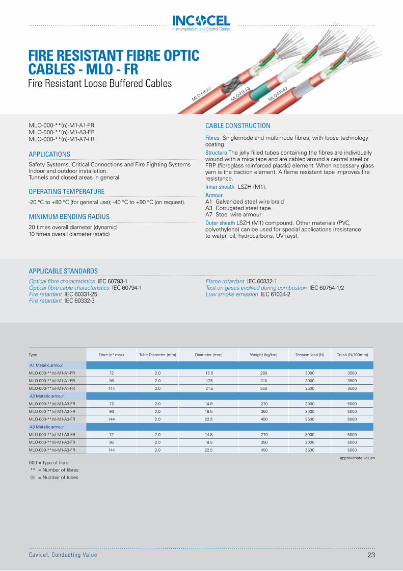
FIRE RESISTANT FIBRE OPTIC CABLES - MLO - FR
MLO-FR-A3
MLO-FR-A1
MLO-FR-A7
APPLICATIONSSafety Systems, Critical Connections and Fire Fighting SystemsIndoor and outdoor installation.Tunnels and closed areas in general.
OPERATING TEMPERATURE-20 °C to +80 °C (for general use); -40 °C to +90 °C (on request).
MINIMUM BENDING RADIUS20 times overall diameter (dynamic)10 times overall diameter (static)
CABLE CONSTRUCTION
Fibres Singlemode and multimode fibres, with loose technology coating.Structure The jelly filled tubes containing the fibres are individually wound with a mica tape and are cabled around a central steel or FRP (fibreglass reinforced plastic) element. When necessary glass yarn is the traction element. A flame resistant tape improves fire resistance.Inner sheath LSZH (M1).ArmourA1 Galvanized steel wire braidA3 Corrugated steel tapeA7 Steel wire armourOuter sheath LSZH (M1) compound. Other materials (PVC, polyethylene) can be used for special applications (resistance to water, oil, hydrocarbons, UV rays).
APPLICABLE STANDARDSOptical fibre characteristics IEC 60793-1 Optical fibre cable characteristics IEC 60794-1Fire retardant IEC 60331-25Fire retardant IEC 60332-3
Flame retardant IEC 60332-1Test on gases evolved during combustion IEC 60754-1/2Low smoke emission IEC 61034-2
MLO-000-**(n)-M1-A1-FRMLO-000-**(n)-M1-A3-FRMLO-000-**(n)-M1-A7-FR
Type Fibre (n° max) Tube Diameter (mm) Diameter (mm) Weight (kg/km) Tension load (N) Crush (N/100mm)
A1 Metallic armour
MLO-000-**(n)-M1-A1-FR 72 2.0 15.0 280 3000 3500
MLO-000-**(n)-M1-A1-FR 96 2.0 17.5 310 3000 3500
MLO-000-**(n)-M1-A1-FR 144 2.0 21.5 350 3500 3500
A3 Metallic armour
MLO-000-**(n)-M1-A3-FR 72 2.0 14.8 270 3000 5000
MLO-000-**(n)-M1-A3-FR 96 2.0 18.5 350 3000 5000
MLO-000-**(n)-M1-A3-FR 144 2.0 22.5 450 3500 5000
A3 Metallic armour
MLO-000-**(n)-M1-A3-FR 72 2.0 14.8 270 3000 5000
MLO-000-**(n)-M1-A3-FR 96 2.0 18.5 350 3000 5000
MLO-000-**(n)-M1-A3-FR 144 2.0 22.5 450 3500 5000
approximate values
Fire Resistant Loose Buffered Cables
000 = Type of fibre
** = Number of fibres
(n) = Number of tubes
23Cavicel, Conducting Value
Instrumentation and Control Cables
t
INCOCEL cables are designed and manufactured according to relevant international standards and client specific requirements.Some of these equirements are industry standard whilst other specifications are custom requirements based on a project, environmental or other basis.It is important for manufacturing bespoke cablesto understand the standards, the client, as well as the influence plant and environmental conditions have on the materials used and the manufacturing processes.
It is important to verify compliance of the requirements once the cable has been manufactured. Hence, a qualified/specialized personnel in carrying out these checks, as well as advanced testing equipment are necessary. Cavicel has as fully equipped lab enabling it to carry out the required electrical, mechanical, chemical and functional tests. The team conducting these tests are specialized and have the know-how experience to conduct these test to its best, following detailed Inspection and Testing Plans approved by our clients.
CERTIFIED QUALITYOn top of the requirements detailed in the standards, depending on their use, cables have to withstand harsh environments and conditions:
RESISTANCE TO EXTREME TEMPERATURES
RESISTANCE TO HUMIDITY
RESISTANCE TO CORROSIVE ENVIRONMENTS
RESISTANCE TO CHEMICAL ENVIRONMENTS
HIGH MECHANICAL RESISTANCE
HEALTH & SAFETY REQUIREMENTS: FIRE RESISTANCE AND FLAME RETARDANT
RESISTANCE AGAINST RODENTS AND TERMITES
Cavicel Cables distinct itself from other manufacturers by performing to its best even in the harshest conditions.
Reliability is our Specialty.
KNOW HOW
AND EXPERTISE
RESEARCH
AND DEVELOPMENT
ADVANCED TEST
FACILITIES
PERFORMANCES
Instrumentation and Control Cables
Instrumentation and Control Cables
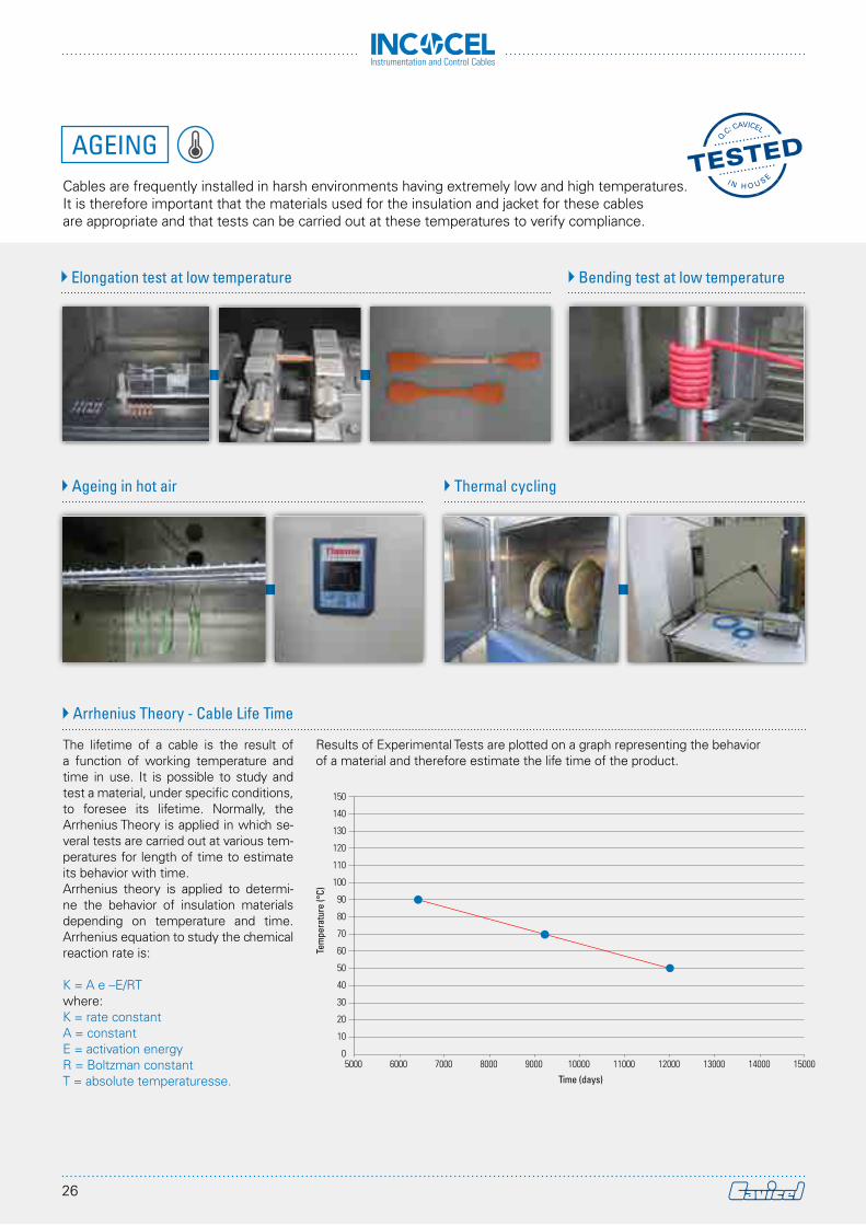
AGEINGCables are frequently installed in harsh environments having extremely low and high temperatures. It is therefore important that the materials used for the insulation and jacket for these cables are appropriate and that tests can be carried out at these temperatures to verify compliance.
The lifetime of a cable is the result of a function of working temperature and time in use. It is possible to study and test a material, under specific conditions, to foresee its lifetime. Normally, the Arrhenius Theory is applied in which se-veral tests are carried out at various tem-peratures for length of time to estimate its behavior with time.Arrhenius theory is applied to determi-ne the behavior of insulation materials depending on temperature and time. Arrhenius equation to study the chemical reaction rate is:
K = A e –E/RTwhere:K = rate constantA = constantE = activation energyR = Boltzman constantT = absolute temperaturesse.
Results of Experimental Tests are plotted on a graph representing the behavior of a material and therefore estimate the life time of the product.
Elongation test at low temperature Bending test at low temperature
Ageing in hot air Thermal cycling
Arrhenius Theory - Cable Life Time
150
140
130
120
110
100
90
80
70
60
50
40
30
20
10
05000 8000 110006000 9000 12000 140007000 10000 13000 15000
Tem
pera
ture
(°C)
Time (days)
26
Instrumentation and Control Cables
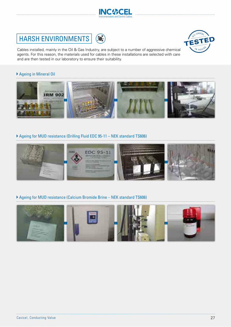
HARSH ENVIRONMENTSCables installed, mainly in the Oil & Gas Industry, are subject to a number of aggressive chemical agents. For this reason, the materials used for cables in these installations are selected with care and are then tested in our laboratory to ensure their suitability.
Ageing in Mineral Oil
Ageing for MUD resistance (Drilling Fluid EDC 95-11 – NEK standard TS606)
Ageing for MUD resistance (Calcium Bromide Brine – NEK standard TS606)
27Cavicel, Conducting Value
Instrumentation and Control Cables
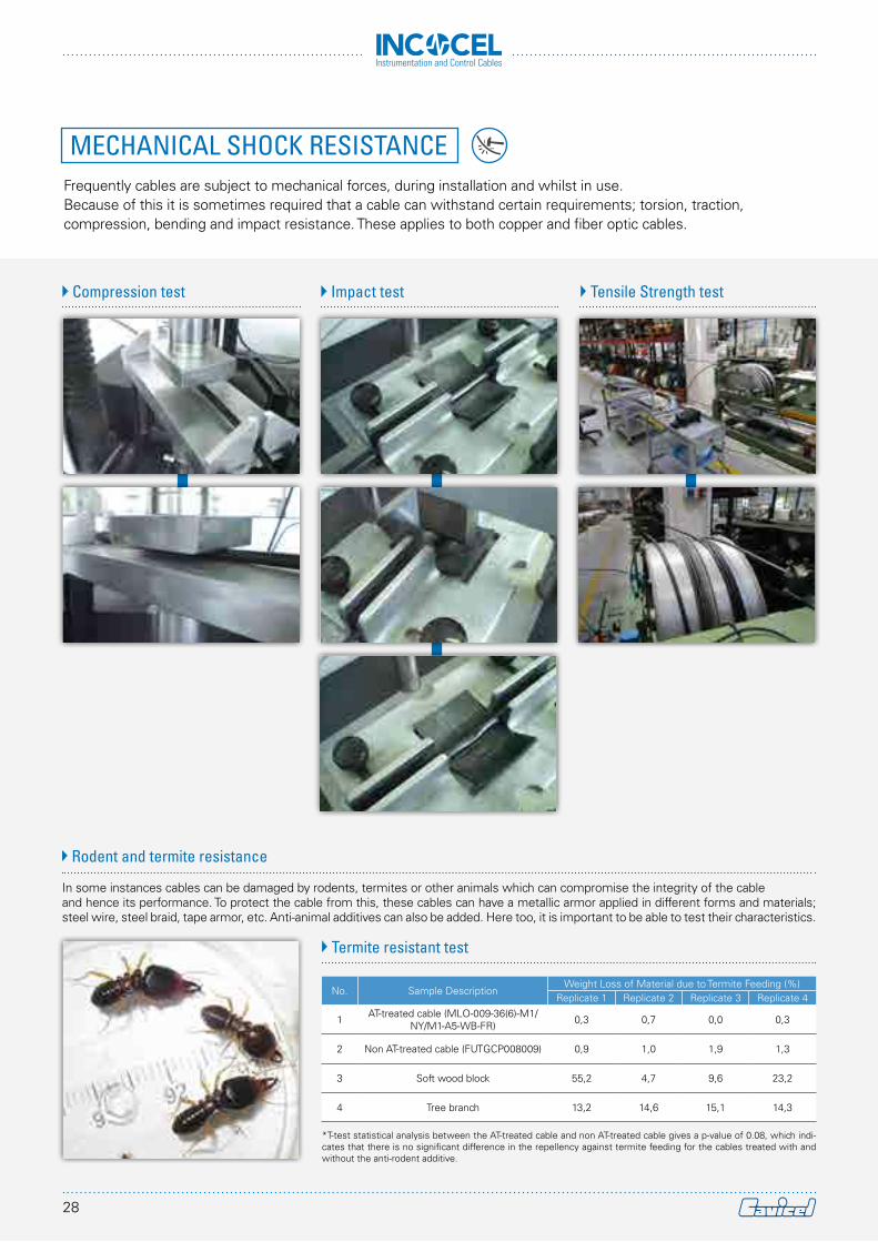
MECHANICAL SHOCK RESISTANCEFrequently cables are subject to mechanical forces, during installation and whilst in use. Because of this it is sometimes required that a cable can withstand certain requirements; torsion, traction, compression, bending and impact resistance. These applies to both copper and fiber optic cables.
In some instances cables can be damaged by rodents, termites or other animals which can compromise the integrity of the cable and hence its performance. To protect the cable from this, these cables can have a metallic armor applied in different forms and materials; steel wire, steel braid, tape armor, etc. Anti-animal additives can also be added. Here too, it is important to be able to test their characteristics.
Compression test Impact test Tensile Strength test
Rodent and termite resistance
Termite resistant test
No. Sample DescriptionWeight Loss of Material due to Termite Feeding (%)
Replicate 1 Replicate 2 Replicate 3 Replicate 4
1 AT-treated cable (MLO-009-36(6)-M1/NY/M1-A5-WB-FR) 0,3 0,7 0,0 0,3
2 Non AT-treated cable (FUTGCP008009) 0,9 1,0 1,9 1,3
3 Soft wood block 55,2 4,7 9,6 23,2
4 Tree branch 13,2 14,6 15,1 14,3
*T-test statistical analysis between the AT-treated cable and non AT-treated cable gives a p-value of 0.08, which indi-cates that there is no significant difference in the repellency against termite feeding for the cables treated with and without the anti-rodent additive.
28
Instrumentation and Control Cables
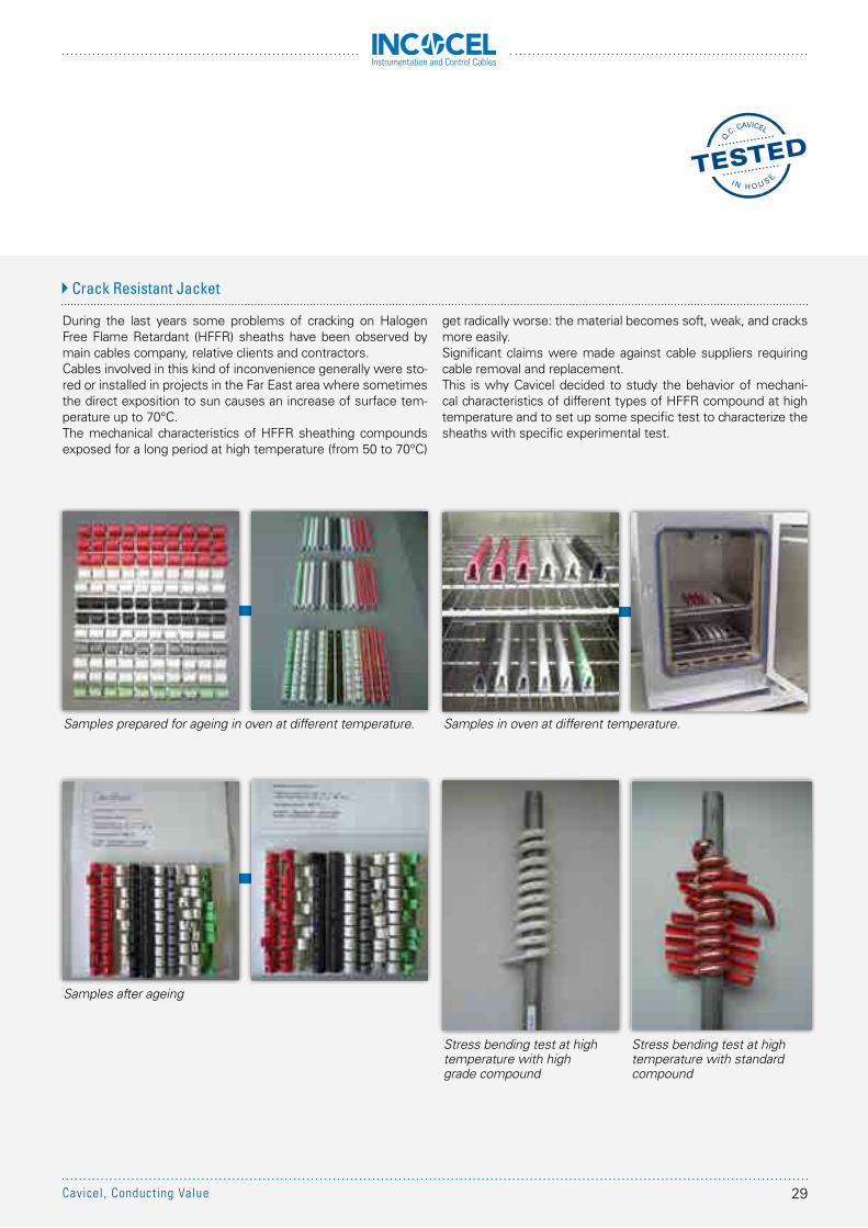
During the last years some problems of cracking on Halogen Free Flame Retardant (HFFR) sheaths have been observed by main cables company, relative clients and contractors.Cables involved in this kind of inconvenience generally were sto-red or installed in projects in the Far East area where sometimes the direct exposition to sun causes an increase of surface tem-perature up to 70°C.The mechanical characteristics of HFFR sheathing compounds exposed for a long period at high temperature (from 50 to 70°C)
Samples prepared for ageing in oven at different temperature.
Samples after ageing
Samples in oven at different temperature.
Stress bending test at high temperature with high grade compound
Stress bending test at high temperature with standard compound
Crack Resistant Jacket
get radically worse: the material becomes soft, weak, and cracks more easily.Significant claims were made against cable suppliers requiring cable removal and replacement.This is why Cavicel decided to study the behavior of mechani-cal characteristics of different types of HFFR compound at high temperature and to set up some specific test to characterize the sheaths with specific experimental test.
29Cavicel, Conducting Value
Instrumentation and Control Cables
FIRE PERFORMANCE TESTS
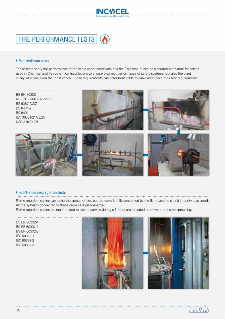
These tests verify the performance of the cable under conditions of a fire. This feature can be a paramount feature for cables used in Chemical and Petrochemical Installations to ensure a correct performance of safety systems, but also the plant in any situation, even the most critical. These requirements can differ from cable to cable and hence their test requirements.
Flame retardant cables can resist the spread of fire, but the cable is fully consumed by the flame and no circuit integrity is assured.All the systems connected to these cables are disconnected.Flame retardant cables are not intended to assure service during a fire but are intended to prevent the flame spreading.
BS EN 50200NS EN 50200 – Annex EBS 6387 CWZBS 8434-2BS 8491IEC 30331-21/23/25NFC 32070 CR1
BS EN 60332-1BS EB 60332-2BS EN 60332-3IEC 60332-1IEC 60332-2IEC 60332-3
Fire resistant tests
Fire/Flame propagation tests
30
Instrumentation and Control Cables
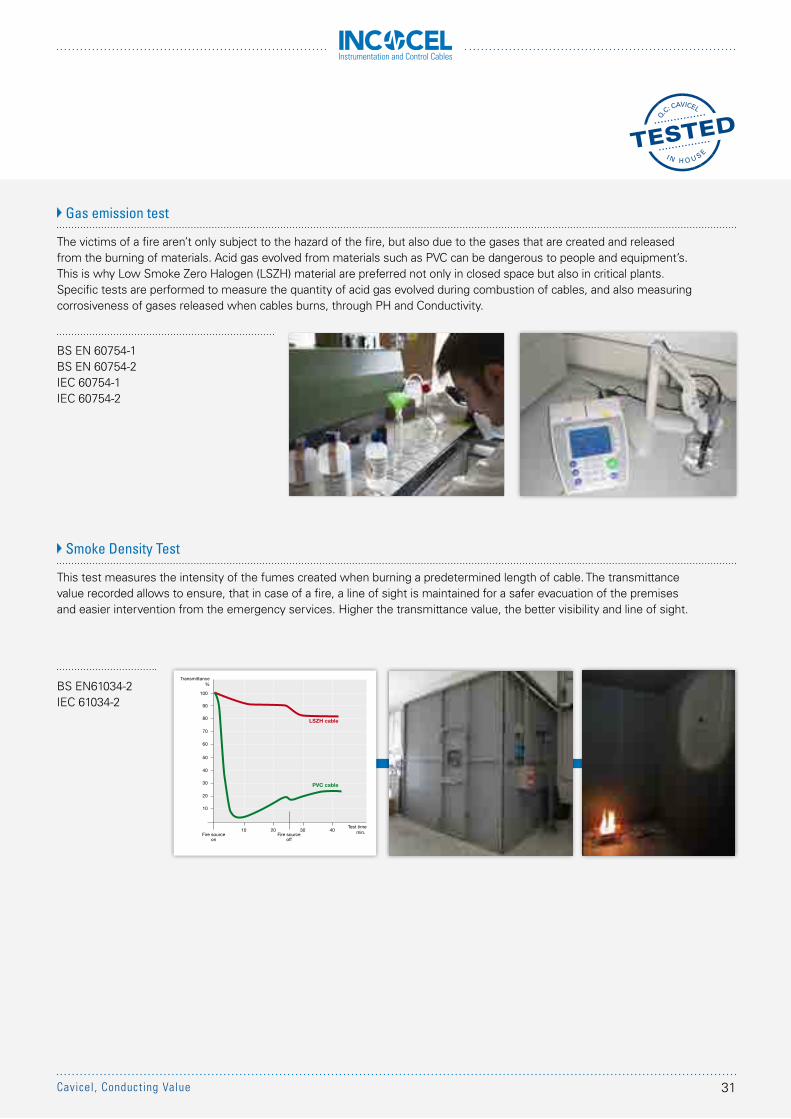
The victims of a fire aren’t only subject to the hazard of the fire, but also due to the gases that are created and released from the burning of materials. Acid gas evolved from materials such as PVC can be dangerous to people and equipment’s.This is why Low Smoke Zero Halogen (LSZH) material are preferred not only in closed space but also in critical plants.Specific tests are performed to measure the quantity of acid gas evolved during combustion of cables, and also measuring corrosiveness of gases released when cables burns, through PH and Conductivity.
This test measures the intensity of the fumes created when burning a predetermined length of cable. The transmittance value recorded allows to ensure, that in case of a fire, a line of sight is maintained for a safer evacuation of the premises and easier intervention from the emergency services. Higher the transmittance value, the better visibility and line of sight.
BS EN 60754-1BS EN 60754-2IEC 60754-1IEC 60754-2
BS EN61034-2IEC 61034-2
Gas emission test
Smoke Density Test
LSZH cable
PVC cable
10 20 30 40Fire source
off
Test timemin. Fire source
on
10
20
30
40
50
60
70
80
90
100
Transmittance%
31Cavicel, Conducting Value
Instrumentation and Control Cables
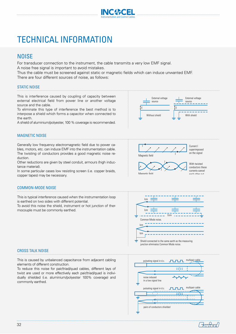
For transducer connection to the instrument, the cable transmits a very low EMF signal.A noise free signal is important to avoid mistakes.Thus the cable must be screened against static or magnetic fields which can induce unwanted EMF.There are four different sources of noise, as follows:
E
Without shield
External voltagesource
With shield
External voltagesource
E
I
I
I
I
Magnetic field
Magnetic field
Current I superimposed on the signal
With twistedconductors these currents cancel each other out
Ecm
Icm
Icm
Common Mode noise.
Icm
Icm
Shield connected to the same earth as the measuring junction eliminates Common Mode noise.
pulsating signal in d.c.
noise induced in a low signal line
multipair cable
pairs of conductors shielded
pulsating signal in d.c. multipair cable
NOISE
CROSS TALK NOISE
This is caused by unbalanced capacitance from adjacent cabling elements of different construction.To reduce this noise for pair/triad/quad cables, different lays of twist are used or more effectively each pair/triad/quad is indivi-dually shielded (i.e. aluminium/polyester 100% coverage) and commonly earthed.
COMMON-MODE NOISE
This is typical interference caused when the instrumentation loop is earthed on two sides with different potential.To avoid this noise the shield, instrument or hot junction of ther-mocouple must be commonly earthed.
MAGNETIC NOISE
Generally low frequency electromagnetic field due to power ca-bles, motors, etc. can induce EMF into the instrumentation cable.The twisting of conductors provides a good magnetic noise re-duction.Other reductions are given by steel conduit, armours (high induc-tance material).In some particular cases low resisting screen (i.e. copper braids, copper tapes) may be necessary.
STATIC NOISE
This is interference caused by coupling of capacity between external electrical field from power line or another voltage source and the cable.To eliminate this type of interference the best method is to interpose a shield which forms a capacitor when connected to the earth.A shield of aluminium/polyester, 100 % coverage is recommended.
TECHNICAL INFORMATION
32
Instrumentation and Control Cables
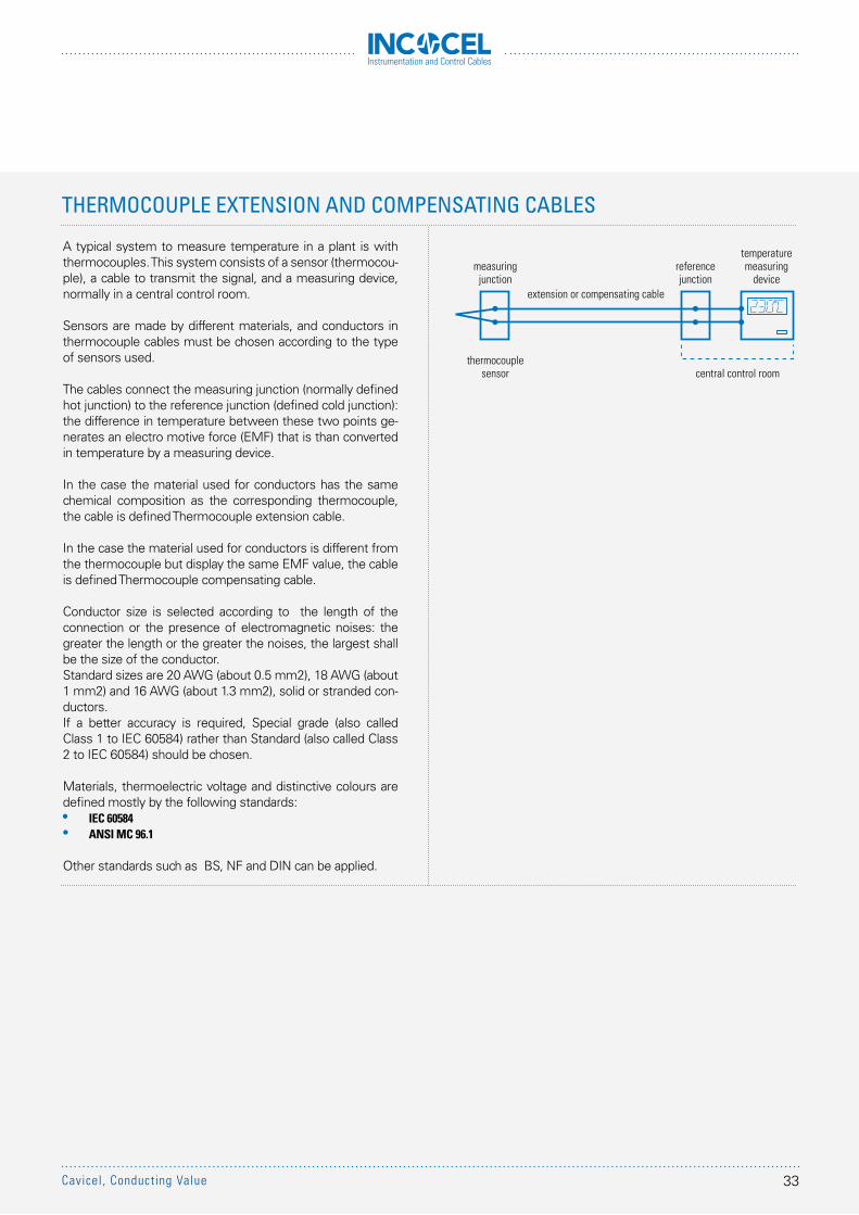
A typical system to measure temperature in a plant is with thermocouples. This system consists of a sensor (thermocou-ple), a cable to transmit the signal, and a measuring device, normally in a central control room.
Sensors are made by different materials, and conductors in thermocouple cables must be chosen according to the type of sensors used.
The cables connect the measuring junction (normally defined hot junction) to the reference junction (defined cold junction): the difference in temperature between these two points ge-nerates an electro motive force (EMF) that is than converted in temperature by a measuring device.
In the case the material used for conductors has the same chemical composition as the corresponding thermocouple, the cable is defined Thermocouple extension cable.
In the case the material used for conductors is different from the thermocouple but display the same EMF value, the cable is defined Thermocouple compensating cable.
Conductor size is selected according to the length of the connection or the presence of electromagnetic noises: the greater the length or the greater the noises, the largest shall be the size of the conductor.Standard sizes are 20 AWG (about 0.5 mm2), 18 AWG (about 1 mm2) and 16 AWG (about 1.3 mm2), solid or stranded con-ductors.If a better accuracy is required, Special grade (also called Class 1 to IEC 60584) rather than Standard (also called Class 2 to IEC 60584) should be chosen.
Materials, thermoelectric voltage and distinctive colours are defined mostly by the following standards:•• IEC 60584• ANSI MC 96.1
Other standards such as BS, NF and DIN can be applied.
measuringjunction
thermocouplesensor central control room
referencejunction
temperaturemeasuring
deviceextension or compensating cable
THERMOCOUPLE EXTENSION AND COMPENSATING CABLES
33Cavicel, Conducting Value
Instrumentation and Control Cables
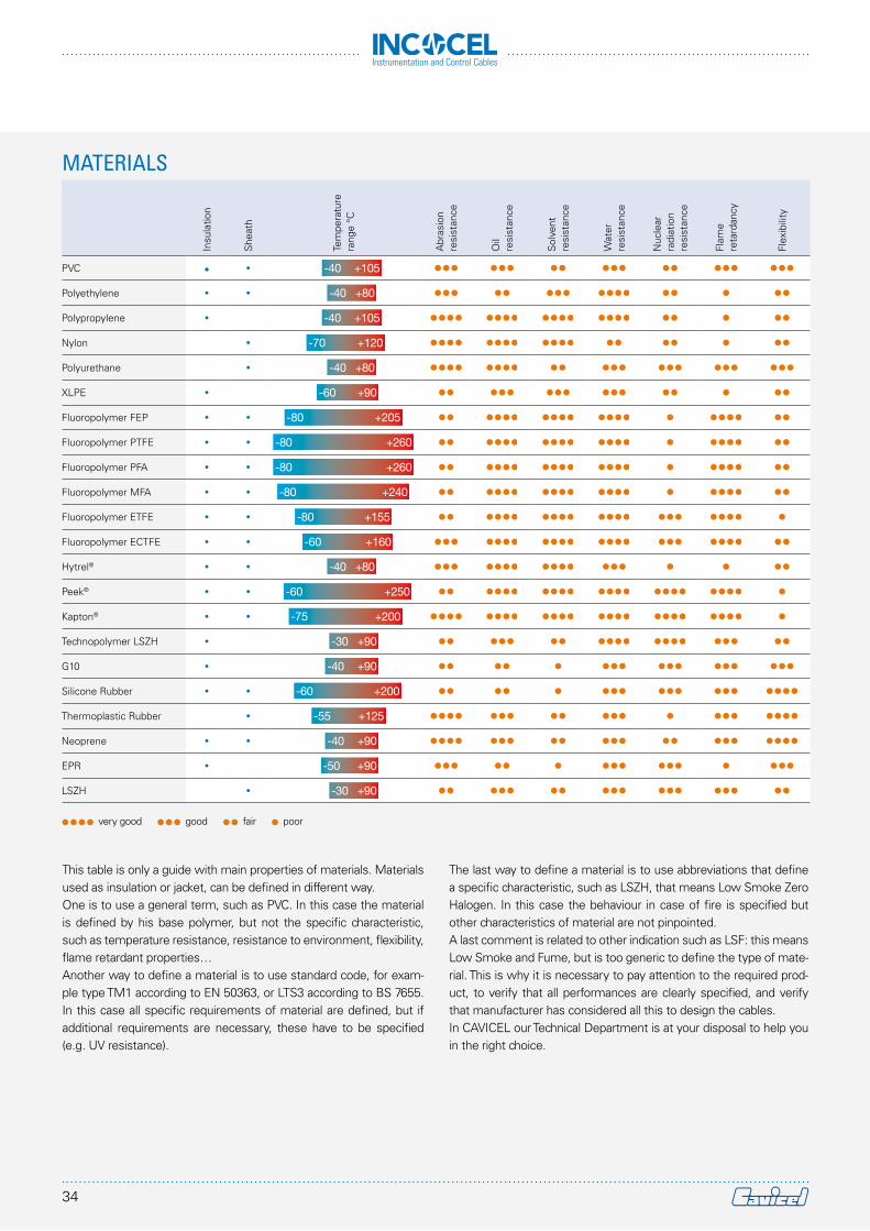
This table is only a guide with main properties of materials. Materials used as insulation or jacket, can be defined in different way. One is to use a general term, such as PVC. In this case the material is defined by his base polymer, but not the specific characteristic, such as temperature resistance, resistance to environment, flexibility, flame retardant properties…Another way to define a material is to use standard code, for exam-ple type TM1 according to EN 50363, or LTS3 according to BS 7655. In this case all specific requirements of material are defined, but if additional requirements are necessary, these have to be specified (e.g. UV resistance).
Insu
latio
n
She
ath
Tem
pera
ture
rang
e °C
Abr
asio
n re
sist
ance
Oil
resi
stan
ce
Sol
vent
resi
stan
ce
Wat
erre
sist
ance
Nuc
lear
ra
diat
ion
resi
stan
ce
Flam
e re
tard
ancy
Flex
ibili
ty
PVC • • -40 +105
Polyethylene • • -40 +80
Polypropylene • -40 +105
Nylon • -70 +120
Polyurethane • -40 +80
XLPE • -60 +90
Fluoropolymer FEP • • -80 +205
Fluoropolymer PTFE • • -80 +260
Fluoropolymer PFA • • -80 +260
Fluoropolymer MFA • • -80 +240
Fluoropolymer ETFE • • -80 +155
Fluoropolymer ECTFE • • -60 +160
Hytrel® • • -40 +80
Peek® • • -60 +250
Kapton® • • -75 +200
Technopolymer LSZH • -30 +90
G10 • -40 +90
Silicone Rubber • • -60 +200
Thermoplastic Rubber • -55 +125
Neoprene • • -40 +90
EPR • -50 +90
LSZH • -30 +90
very good good fair poor
MATERIALS
The last way to define a material is to use abbreviations that define a specific characteristic, such as LSZH, that means Low Smoke Zero Halogen. In this case the behaviour in case of fire is specified but other characteristics of material are not pinpointed.A last comment is related to other indication such as LSF: this means Low Smoke and Fume, but is too generic to define the type of mate-rial. This is why it is necessary to pay attention to the required prod-uct, to verify that all performances are clearly specified, and verify that manufacturer has considered all this to design the cables. In CAVICEL our Technical Department is at your disposal to help you in the right choice.
34
Instrumentation and Control Cables
Nominal section(mm2)
Min. nr wires in conductor
Class 1
Min. nr wires in conductor
Class 2
Max. wire dia. of conductor
Class 5(mm)
Max. wire dia. of conductor
Class 6(mm)
Max. Conductor Resistance at 20 °C in d.c.
class 1 and class 2 class 5 and class 6
Copper(ohm/km)
Tinned Copper(ohm/km)
Copper(ohm/km)
Tinned Copper(ohm/km)
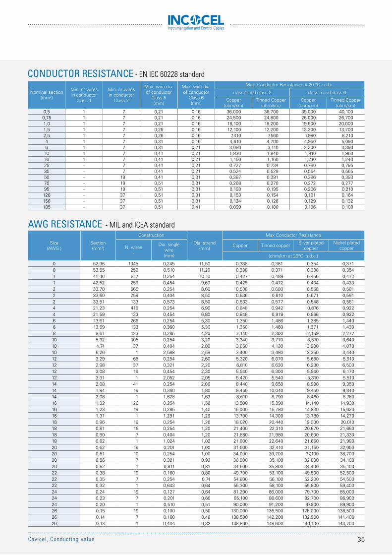
0,5 1 7 0,21 0,16 36,000 36,700 39,000 40,1000,75 1 7 0,21 0,16 24,500 24,800 26,000 26,7001,0 1 7 0,21 0,16 18,100 18,200 19,500 20,0001,5 1 7 0,26 0,16 12,100 12,200 13,300 13,7002,5 1 7 0,26 0,16 7,410 7,560 7,980 8,2104 1 7 0,31 0,16 4,610 4,700 4,950 5,0906 1 7 0,31 0,21 3,080 3,110 3,300 3,39010 1 7 0,41 0,21 1,830 1,840 1,910 1,95016 1 7 0,41 0,21 1,150 1,160 1,210 1,24025 - 7 0,41 0,21 0.727 0,734 0,780 0,79535 - 7 0,41 0,21 0,524 0,529 0,554 0,56550 - 19 0,41 0,31 0,387 0,391 0,386 0,39370 - 19 0,51 0,31 0,268 0,270 0,272 0,27795 - 19 0,51 0,31 0.193 0,195 0,206 0,210120 - 37 0,51 0,31 0,153 0,154 0,161 0,164150 - 37 0,51 0,31 0,124 0,126 0,129 0,132185 - 37 0,51 0,41 0,099 0,100 0,106 0,108
CONDUCTOR RESISTANCE - EN IEC 60228 standard
AWG RESISTANCE - MIL and ICEA standard
Size(AWG )
Section(mm2)
Construction
Dia. strand (mm)
Max Conductor Resistance
N. wires-
Dia. single wire(mm)
Copper Tinned copper Silver plated copper
Nichel plated copper
(ohm/km at 20°C in d.c.)
0 52,95 1045 0,245 11,50 0,338 0,381 0,354 0,3710 53,55 259 0,510 11,20 0,338 0,371 0,338 0,3541 41,40 817 0,254 10,10 0,427 0,489 0,456 0,4721 42,52 259 0,454 9,60 0,425 0,472 0,404 0,4232 33,70 665 0,254 8,60 0,538 0,600 0,558 0,5812 33,60 259 0,404 8,50 0,536 0,610 0,571 0,5912 33,51 133 0,573 8,50 0,533 0,577 0,548 0,5614 21,23 418 0,254 6,90 0,848 0,942 0,876 0,9224 21,59 133 0,454 6,80 0,848 0,919 0,866 0,9226 13,61 266 0,254 5,30 1,350 1,486 1,385 1,4406 13,59 133 0,360 5,30 1,350 1,460 1,371 1,4308 8,61 133 0,285 4,20 2,140 2,300 2,159 2,27710 5,32 105 0,254 3,20 3,340 3,770 3,510 3,64010 4,74 37 0,404 2,80 3,850 4,130 3,900 4,07010 5,26 1 2,588 2,59 3,400 3,480 3,350 3,44012 3,29 65 0,254 2,60 5,320 6,070 5,680 5,91012 2,98 37 0,321 2,20 6,810 6,630 6,230 6,50012 3,08 19 0,454 2,30 5,940 6,300 5,940 6,17012 3,31 1 2,052 2,05 5,420 5,540 5,310 5,51014 2,08 41 0,254 2,00 8,440 9,650 8,990 9,35014 1,94 19 0,360 1,80 9,450 10,040 9,450 9,84014 2,08 1 1,628 1,63 8,610 8,790 8,460 8,76016 1,32 26 0,254 1,50 13,500 15,390 14,140 14,93016 1,23 19 0,285 1,40 15,000 15,780 14,830 15,62016 1,31 1 1,291 1,29 13,700 14,300 13,780 14,27018 0,96 19 0,254 1,26 18,020 20,440 19,000 20,01018 0,81 16 0,254 1,20 21,400 22,310 20,670 21,65018 0,90 7 0,404 1,20 21,880 21,980 20,600 21,33018 0,82 1 1,024 1,02 21,800 22,640 21,650 21,98020 0,62 19 0,201 1,00 31,600 32,410 31,150 32,05020 0,51 10 0,254 1,00 34,000 39,700 37,100 38,70020 0,56 7 0,321 0,92 36,000 35,100 32,800 34,10020 0,52 1 0,811 0,81 34,600 35,800 34,400 35,10022 0,38 19 0,160 0,80 49,700 53,100 49,500 52,50022 0,35 7 0,254 0,74 54,800 56,100 52,200 54,50022 0,32 1 0,643 0,64 55,300 58,100 55,800 59,40024 0,24 19 0,127 0,64 81,200 86,000 79,700 85,00024 0,23 7 0,201 0,60 85,100 88,600 82,700 86,90024 0,20 1 0,510 0,51 90,000 91,200 87,900 89,90026 0,15 19 0,100 0,50 130,000 135,500 126,000 138,50026 0,14 7 0,160 0,48 138,500 142,200 132,900 141,40026 0,13 1 0,404 0,32 138,800 148,600 140,100 143,700
35Cavicel, Conducting Value
Instrumentation and Control Cables
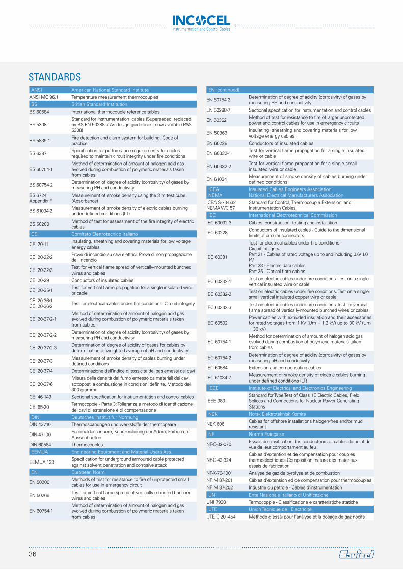
ANSI American National Standard Institute
ANSI MC 96.1 Temperature measurement thermocouples
BS British Standard Institution
BS 60584 International thermocouple reference tables
BS 5308Standard for instrumentation cables (Superseded, replaced by BS EN 50288-7. As design guide lines, now available PAS 5308)
BS 5839-1 Fire detection and alarm system for building. Code of practice
BS 6387 Specification for performance requirements for cables required to maintain circuit integrity under fire conditions
BS 60754-1Method of determination of amount of halogen acid gas evolved during combustion of polymeric materials taken from cables
BS 60754-2 Determination of degree of acidity (corrosivity) of gases by measuring PH and conductivity
BS 6724, Appendix F
Measurement of smoke density using the 3 m test cube (Absorbance)
BS 61034-2 Measurement of smoke density of electric cables burning under defined conditions (LT)
BS 50200 Method of test for assessment of the fire integrity of electric cables
CEI Comitato Elettrotecnico Italiano
CEI 20-11 Insulating, sheathing and covering materials for low voltage energy cables
CEI 20-22/2 Prove di incendio su cavi elettrici. Prova di non propagazione dell’incendio
CEI 20-22/3 Test for vertical flame spread of vertically-mounted bunched wires and cables
CEI 20-29 Conductors of insulated cables
CEI 20-35/1 Test for vertical flame propagation for a single insulated wire or cable
CEI 20-36/1 CEI 20-36/2 Test for electrical cables under fire conditions. Circuit integrity
CEI 20-37/2-1Method of determination of amount of halogen acid gas evolved during combustion of polymeric materials taken from cables
CEI 20-37/2-2 Determination of degree of acidity (corrosivity) of gases by measuring PH and conductivity
CEI 20-37/2-3 Determination of degree of acidity of gases for cables by determination of weighted average of pH and conductivity
CEI 20-37/3 Measurement of smoke density of cables burning under defined conditions
CEI 20-37/4 Determinazione dell’indice di tossicità dei gas emessi dai cavi
CEI 20-37/6Misura della densità del fumo emesso da materiali dei cavi sottoposti a combustione in condizioni definite. Metodo dei 300 grammi
CEI 46-143 Sectional specification for instrumentation and control cables
CEI 65-20 Termocoppie - Parte 3: Tolleranze e metodo di identificazione dei cavi di estensione e di compensazione
DIN Deutsches Institut fur Normung
DIN 43710 Thermospanungen und werkstoffe der thermopaare
DIN 47100 Fernmeldeschnuere; Kennzeichnung der Adern, Farben der Aussenhuellen
DIN 60584 Thermocouples
EEMUA Engineering Equipment and Material Users Ass.
EEMUA 133 Specification for underground armoured cable protected against solvent penetration and corrosive attack
EN European Norm
EN 50200 Methods of test for resistance to fire of unprotected small cables for use in emergency circuit
EN 50266 Test for vertical flame spread of vertically-mounted bunched wires and cables
EN 60754-1Method of determination of amount of halogen acid gas evolved during combustion of polymeric materials taken from cables
EN (continued)
EN 60754-2 Determination of degree of acidity (corrosivity) of gases by measuring PH and conductivity
EN 50288-7 Sectional specification for instrumentation and control cables
EN 50362 Method of test for resistance to fire of larger unprotected power and control cables for use in emergency circuits
EN 50363 Insulating, sheathing and covering materials for low voltage energy cables
EN 60228 Conductors of insulated cables
EN 60332-1 Test for vertical flame propagation for a single insulated wire or cable
EN 60332-2 Test for vertical flame propagation for a single small insulated wire or cable
EN 61034 Measurement of smoke density of cables burning under defined conditions
ICEANEMA
Insulated Cables Engineers AssociationNational Electrical Manufacturers Association
ICEA S-73-532 NEMA WC 57
Standard for Control, Thermocouple Extension, and Instrumentation Cables
IEC International Electrotechnical Commission
IEC 60092-3 Cables: construction, testing and installation
IEC 60228 Conductors of insulated cables - Guide to the dimensional limits of circular connectors
IEC 60331
Test for electrical cables under fire conditions. Circuit integrity. Part 21 - Cables of rated voltage up to and including 0.6/ 1.0 kV Part 23 - Electric data cablesPart 25 - Optical fibre cables
IEC 60332-1 Test on electric cables under fire conditions. Test on a single vertical insulated wire or cable
IEC 60332-2 Test on electric cables under fire conditions. Test on a single small vertical insulated copper wire or cable
IEC 60332-3 Test on electric cables under fire conditions.Test for vertical flame spread of vertically-mounted bunched wires or cables
IEC 60502Power cables with extruded insulation and their accessories for rated voltages from 1 kV (Um = 1,2 kV) up to 30 kV (Um = 36 kV)
IEC 60754-1Method for determination of amount of halogen acid gas evolved during combustion of polymeric materials taken from cables
IEC 60754-2 Determination of degree of acidity (corrosivity) of gases by measuring pH and conducivity
IEC 60584 Extension and compensating cables
IEC 61034-2 Measurement of smoke density of electric cables burning under defined conditions (LT)
IEEE Institute of Electrical and Electronics Engineering
IEEE 383Standard for Type Test of Class 1E Electric Cables, Field Splices and Connections for Nuclear Power Generating Stations
NEK Norsk Elektroteknisk Komite
NEK 606 Cables for offshore installations halogen-free and/or mud resistant
NF Norme Française
NF-C-32-070 Essais de clasification des conducteurs et cables du point de vue de leur comportament au feu
NF-C-42-324Cables d'extention et de compensation pour couples thermoelectriques.Composition, nature des materiaux, essais de fabrication
NF-X-70-100 Analyse de gaz de pyrolyse et de combustion
NF M 87-201 Câbles d'extension ed de compensation pour thermocouples
NF M 87-202 Industrie du pétrole - Câbles d'instrumentation
UNI Ente Nazionale Italiano di Unificazione
UNI 7938 Termocoppie - Classificazione e caratteristiche statiche
UTE Union Tecnique de l’Electricitè
UTE C 20 -454 Methode d’essai pour l’analyse et la dosage de gaz nocifs
STANDARDS
36
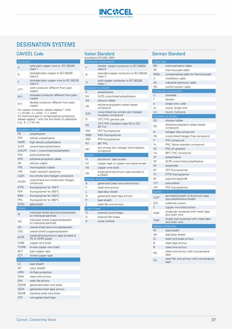
Instrumentation and Control Cables
CAVICEL CodeConductor
U solid plain copper wire to IEC 60228 class 1
R stranded plain copper to IEC 60228 class 2
F stranded plain copper wire to IEC 60228 class 5
U(*) solid conductor different from plain copper
R(*) stranded conductor different from plain copper
F(*) flexible conductor different from plain copper
For copper conductor, please replace * with: t = tinned - s = silver - n = nickelFor thermocouple or compensating conductors, please replace * with the first letter of calibration e.g.: K, J, T, W, etc.
Insulation / sheath
PE polyethylene
FPE cellular polyethylene
HDPE high density polyethylene
XLPE cross-linked polyethylene
mXLPE mica + cross-linked polyethylene
PVC polyvinylchloride
EPR ethylene-propylene rubber
SR silicone rubber
TPE thermoplastic rubber
HTE heath resistant elastomer
LSZH low smoke zero halogen compound
XLSZH cross-linked low smoke zero halogen compound
ETFE fluoropolymer for 150°C
FEP fluoropolymer for 205°C
MFA fluoropolymer for 230°C
PFA fluoropolymer for 260°C
GTEX glass braid
Shield
IS individual shield (aluminium/polyester) on individual pair/triad
ISC individual shield (copper/polyester) on individual pair/triad
OS overall shield (aluminium/polyester)
OSC overall shield (copper/polyester)
ALPE longitudinal aluminium tape bonded to PE or HDPE jacket
CWB copper wire braid
TCWB tinned copper wire braid
BCT bare copper tape
TCT tinned copper tape
Armour/protection
LC lead sheath
NC nylon sheath
HIPK Hi-Pack protection
SWA steel wire armour
SFA steel flat armour
GSWB galvanized steel wire braid
GSTA galvanized steel tape armour
SSWB stainless steel wire braid
CST corrugated steel tape
Italian Standardaccording to CEI-UNEL 35011
Conductor construction
F flexible copper conductor to IEC 60228 class 5
R stranded copper conductor to IEC 60228 class 2
U solid copper conductor to IEC 60228 class 1
Insulation or sheath
E polyethylene
E4 XLPE cross-linked polyethylene
G4 silicone rubber
G5 ethylene-propylene rubber based compound
G10 cross-linked low smoke zero halogen insulation compound
R 70°C PVC general use
R2 70°C PVC insulation type R2 to CEI 20-11w
R5F FEP fluoropolymer
R5M MFA fluoropolymer
R5P PFA fluoropolymer
R7 90° PVC
M1 low smoke zero halogen thermoplastic compound
Screen
H aluminium tape screen
H1 copper tape or copper wire spiral screen
H2 copper wire braid
H5 longitudinal aluminium tape bonded to a sheath
Metallic protection
A galvanized steel wire braid armour
F steel wire armour
L lead alloy sheath
N galvanized steel tape armour
P lead sheath
Z steel flat wire armour
Cable shape
O external round shape
D external flat shape
X cores twisted
German StandardCable type
RE- instrumentation cable
RT- thermocouple cable
RAGL- compensating cable for thermocouple
J- installation cable
JE- industrial electronic cable
RD- control system cable
Conductor construction
Li stranded
f flexible
e single wire, solid
re- round, single wire
rm- round, multiwire
Insulation or sheath
2G silicone rubber
3G ethylene-propylene rubber based compound
H halogen free compound
HX cross-linked halogen free compound
Y PVC compound
Yu PVC, flame retardant compound
Yö PVC oil resistant
Yw 90°C PVC compound
2Y polyethylene
2X XLPE cross-linked polyethylene
4Y polyamide
6Y FEP fluoropolymer
7Y ETFE fluoropolymer
8Y polyimid Kapton®
11Y polyurethan
14Y PFA fluoropolymer
Screen
(L)2Y laminated sheath of aluminium tape plus polyethylene sheath
(ST) collective screen
C copper wire braid screen
PiMF single pair screened with metal tape plus drain wire
TiMF single triad screened with metal tape plus drain wire
Metallic protection
M lead sheath
Mz lead alloy sheath
Q steel wire braid armour
B steel tape armour
R steel wire armour
RG steel wire armour with counterspiral tape
FG steel flat wire armour with counterspiral tape
DESIGNATION SYSTEMS
37Cavicel, Conducting Value
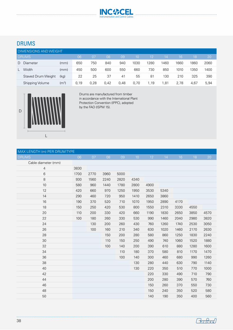
Instrumentation and Control Cables
MAX LENGTH (m) PER DRUM TYPE
DRUMS 06 07 08 09 10 12 14 16 18 20
Cable diameter (mm)
4 3830
6 1700 2770 3960 5000
8 930 1560 2240 2820 4340
10 580 960 1440 1780 2800 4900
12 420 660 970 1250 1950 3530 5340
14 290 460 720 950 1410 2650 3860
16 190 370 520 710 1070 1950 2890 4170
18 150 250 420 530 800 1550 2310 3330 4550
20 110 200 330 420 660 1190 1830 2650 3850 4570
22 100 180 260 330 530 990 1460 2040 2980 3820
24 130 200 260 430 760 1260 1740 2530 3050
26 100 160 210 340 630 1020 1460 2170 2630
28 150 200 280 580 860 1250 1830 2240
30 110 150 250 490 740 1060 1520 1880
32 100 140 200 390 610 880 1280 1600
34 110 180 370 580 810 1170 1470
36 100 140 300 460 680 990 1260
38 130 280 440 630 790 1140
40 130 220 350 510 770 1000
42 220 330 490 710 790
44 200 280 390 570 760
46 150 260 370 550 730
48 150 240 350 520 580
50 140 190 350 400 560
DIMENSIONS AND WEIGHT
DRUMS 06 07 08 09 10 12 14 16 18 20
D Diameter (mm) 650 750 840 940 1030 1280 1460 1660 1860 2060
L Width (mm) 450 500 600 550 660 730 850 1010 1350 1400
Staved Drum Weight (kg) 22 25 37 41 55 81 130 210 325 390
Shipping Volume (m3) 0,19 0,28 0,42 0,48 0,70 1,19 1,81 2,78 4,67 5,94
DRUMS
D
L
Drums are manufactured from timber in accordance with the International Plant Protection Convention (IPPC), adoptedby the FAO (ISPM 15).
38
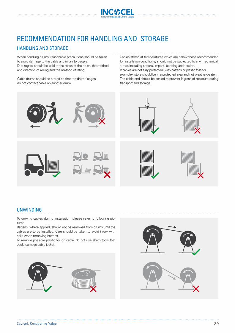
Instrumentation and Control Cables
When handling drums, reasonable precautions should be taken to avoid damage to the cable and injury to people. Due regard should be paid to the mass of the drum, the method and direction of rolling and the method of lifting.
Cable drums should be stored so that the drum flanges do not contact cable on another drum.
To unwind cables during installation, please refer to following pic-tures.Battens, where applied, should not be removed from drums until the cables are to be installed. Care should be taken to avoid injury with nails when removing battens.To remove possible plastic foil on cable, do not use sharp tools that could damage cable jacket.
HANDLING AND STORAGE
UNWINDING
Cables stored at temperatures which are below those recommended for installation conditions, should not be subjected to any mechanical stress including shocks, impact, bending and torsion.If cables are not fully protected (with battens or plastic foils for example), store should be in a protected area and not weather-beaten.The cable end should be sealed to prevent ingress of moisture during transport and storage.
RECOMMENDATION FOR HANDLING AND STORAGE
39Cavicel, Conducting Value
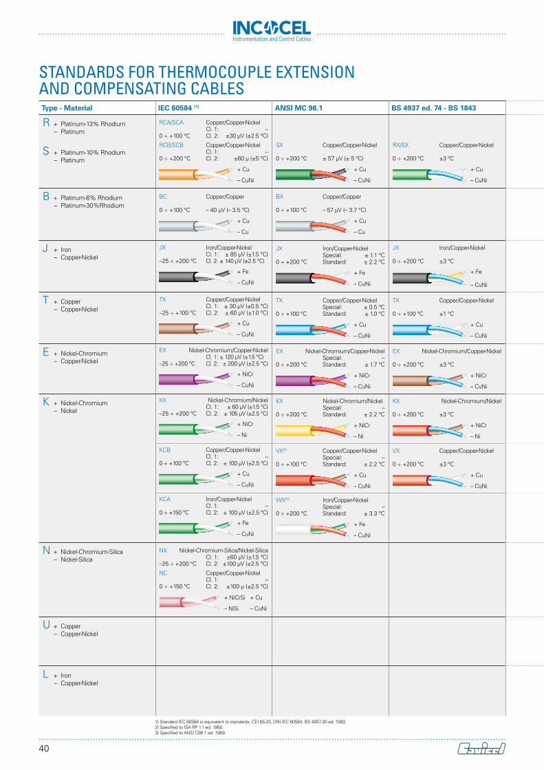
Instrumentation and Control Cables
STANDARDS FOR THERMOCOUPLE EXTENSION AND COMPENSATING CABLES
Electrical Characteristics (approx. values)
Size(AWG)
Stranding (N°/mm)
Conductors resistance (Ω/km at 20 °C)
Inductance(mH/km)Type - Material IEC 60584 (1) ANSI MC 96.1 BS 4937 ed. 74 - BS 1843 NF C 42-324 DIN 43710 pos. (+) neg. (-)
R + Platinum-13% Rhodium – Platinum
S + Platinum-10% Rhodium – Platinum
RCA/SCA Copper/Copper-Nickel Cl. 1: –0 ÷ +100 °C Cl. 2: ±30 µV (±2.5 °C)
RCB/SCB Copper/Copper-Nickel Cl. 1: –0 ÷ +200 °C Cl. 2: ±60 µ (±5 °C)
+ Cu
– CuNi
SX Copper/Copper-Nickel 0 ÷ +200 °C ± 57 µV (± 5 °C)
+ Cu
– CuNi
RX/SX Copper/Copper-Nickel
0 ÷ +200 °C ±3 °C
+ Cu
– CuNi
SC Copper/Copper-Nickel
–25 ÷ +200 °C ±7.0 °C
+ Cu
– CuNi
SoPtRh/SoPt Copper/Copper-Nickel(RX-SX)0 ÷ +200 °C ±3.0 °C
+ Cu
– CuNi
202018181616
1/0.817/0.321/1.02
10/0.321/1.29
16/0.32
353522231415
2332201471549296
111111
B + Platinum-6% Rhodium – Platinum-30%Rhodium
BC Copper/Copper 0 ÷ +100 °C – 40 µV (– 3.5 °C)
+ Cu
– Cu
BX Copper/Copper 0 ÷ +100 °C – 57 µV (– 3.7 °C)
+ Cu
– Cu
BC Copper/Copper –25 ÷ +200 °C ±4.0 °C
+ Cu
– Cu
202018181616
1/0.817/0.321/1.02
10/0.321/1.29
16/0.32
353522231415
353522231415
111111
J + Iron – Copper-Nickel
JX Iron/Copper-Nickel Cl. 1: ± 85 µV (±1.5 °C)–25 ÷ +200 °C Cl. 2: ± 140 µV (±2.5 °C)
+ Fe
– CuNi
JX Iron/Copper-Nickel Special: ± 1.1 °C0 ÷ +200 °C Standard: ± 2.2 °C
+ Fe
– CuNi
JX Iron/Copper-Nickel 0 ÷ +200 °C ±3 °C
+ Fe
– CuNi
JX/JC Iron/Copper-NickelJX: –25 ÷ +250 °C ±1.5 °CJC: –25 ÷ +250 °C ±3.0 °C
+ Fe
– CuNi
See LX
202018181616
1/0.817/0.321/1.02
10/0.321/1.29
16/0.32
253240160168100103
951897600628375393
666666
T + Copper – Copper-Nickel
TX Copper/Copper-Nickel Cl. 1: ± 30 µV (±0.5 °C)–25 ÷ +100 °C Cl. 2: ± 60 µV (±1.0 °C)
+ Cu
– CuNi
TX Copper/Copper-Nickel Special: ± 0.5 °C0 ÷ +100 °C Standard: ± 1.0 °C
+ Cu
– CuNi
TX Copper/Copper-Nickel 0 ÷ +100 °C ±1 °C
+ Cu
– CuNi
TX/TC Copper/Copper-NickelTX: –25 ÷ +250 °C ±0.5 °CTC: –25 ÷ +100 °C ±1.0 °C
+ Cu
– CuNi
See UX
202018181616
1/0.817/0.321/1.02
10/0.321/1.29
16/0.32
353522231415
951897600628375393
111111
E + Nickel-Chromium – Copper-Nickel
EX Nickel-Chromium/Copper-Nickel Cl. 1: ± 120 µV (±1.5 °C)–25 ÷ +200 °C Cl. 2: ± 200 µV (±2.5 °C)
+ NiCr
– CuNi
EX Nickel-Chromium/Copper-Nickel Special: –0 ÷ +200 °C Standard: ± 1.7 °C
+ NiCr
– CuNi
EX Nickel-Chromium/Copper-Nickel 0 ÷ +200 °C ±3 °C
+ NiCr
– CuNi
EX/EC Nickel-Chromium/Copper-Nickel EX: –25 ÷ +250 °C ±1.5 °CEC: –25 ÷ +250 °C ±3.0 °C
+ NiCr
– CuNi
202018181616
1/0.817/0.321/1.02
10/0.321/1.29
16/0.32
13701292865905540565
951897600628375393
444444
K + Nickel-Chromium – Nickel
KX Nickel-Chromium/Nickel Cl. 1: ± 60 µV (±1.5 °C)–25 ÷ +200 °C Cl. 2: ± 105 µV (±2.5 °C)
+ NiCr
– Ni
KX Nickel-Chromium/Nickel Special: –0 ÷ +200 °C Standard: ± 2.2 °C
+ NiCr
– Ni
KX Nickel-Chromium/Nickel 0 ÷ +200 °C ±3 °C
+ NiCr
– Ni
KX/KC Nickel-Chromium/NickelKX: –25 ÷ +250 °C ±1.5 °CKC: –25 ÷ +200 °C ±3.0 °C
+ NiCr
– Ni
NiCr/Ni Nickel-Chromium/Nickel(KX)0 ÷ +200 °C ±3.0 °C
+ NiCr
– Ni
202018181616
1/0.817/0.321/1.02
10/0.321/1.29
16/0.32
13701292865905540565
567535358375225235
444444
KCB Copper/Copper-Nickel Cl. 1: –0 ÷ +100 °C Cl. 2: ± 100 µV (±2.5 °C)
+ Cu
– CuNi
VX(2) Copper/Copper-Nickel Special: –0 ÷ +100 °C Standard: ± 2.2 °C
+ Cu
– CuNi
VX Copper/Copper-Nickel 0 ÷ +200 °C ±3 °C
+ Cu
– CuNi
VC Copper/Copper-Nickel –25 ÷ +100 °C ±3.0 °C
+ Cu
– CuNi
202018181616
1/0.817/0.321/1.02
10/0.321/1.29
16/0.32
353522231415
951897600628375393
111111
KCA Iron/Copper-Nickel Cl. 1: –0 ÷ +150 °C Cl. 2: ± 100 µV (±2.5 °C)
+ Fe
– CuNi
WX(2) Iron/Copper-Nickel Special: –0 ÷ +200 °C Standard: ± 3.3 °C
+ Fe
– CuNi
WC Iron/Copper-Nickel –25 ÷ +200 °C ± 3.0 °C
+ Fe
– CuNi
SoNiCr/SoNi Iron/Copper-Nickel(WX)0 ÷ +200 °C ±3.0 °C
+ Fe
– CuNi
202018181616
1/0.817/0.321/1.02
10/0.321/1.29
16/0.32
253240160168100103
1010952637666398417
666666
N + Nickel-Chromium-Silica – Nickel-Silica
NX Nickel-Chromium-Silica/Nickel-Silica Cl. 1: ±60 µV (±1.5 °C)–25 ÷ +200 °C Cl. 2: ±100 µV (±2.5 °C)
NC Copper/Copper-Nickel Cl. 1: –0 ÷ +150 °C Cl. 2: ±100 µ (±2.5 °C)
+ NiCrSi
– NiSi
+ Cu
– CuNi
202018181616
1/0.817/0.321/1.02
10/0.321/1.29
16/0.32
1940177612241243
765777
708648446454279284
444444
U + Copper – Copper-Nickel
Cu/CuNi Copper/Copper-Nickel(UX)0 ÷ +200 °C ±3.0 °C
+ Cu
– CuNi
202018181616
1/0.817/0.321/1.02
10/0.321/1.29
16/0.32
353522231415
951897600628375393
111111
L + Iron – Copper-Nickel
Fe/CuNi Iron/Copper-Nickel(LX)0 ÷ +200 °C ±3.0 °C
+ Fe
– CuNi
202018181616
1/0.817/0.321/1.02
10/0.321/1.29
16/0.32
253240160168100103
951897600628375393
666666
1) Standard IEC 60584 is equivalent to standards: CEI 65-20, DIN IEC 60584, BS 4937-30 ed. 1993.2) Specified to ISA RP 1.1 ed. 1950.3) Specified to ANSI C96.1 ed. 1969.
Thermocouples U and L according to DIN 43710 have been replaced respectively by rtype T and J according to IEC 60584, even if e.m.f. values of thermocouples type T and J are different from those of thermocouples type U and L.
40
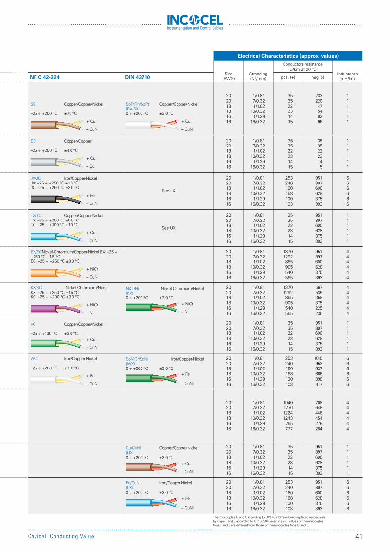
Instrumentation and Control Cables
Electrical Characteristics (approx. values)
Size(AWG)
Stranding (N°/mm)
Conductors resistance (Ω/km at 20 °C)
Inductance(mH/km)Type - Material IEC 60584 (1) ANSI MC 96.1 BS 4937 ed. 74 - BS 1843 NF C 42-324 DIN 43710 pos. (+) neg. (-)
R + Platinum-13% Rhodium – Platinum
S + Platinum-10% Rhodium – Platinum
RCA/SCA Copper/Copper-Nickel Cl. 1: –0 ÷ +100 °C Cl. 2: ±30 µV (±2.5 °C)
RCB/SCB Copper/Copper-Nickel Cl. 1: –0 ÷ +200 °C Cl. 2: ±60 µ (±5 °C)
+ Cu
– CuNi
SX Copper/Copper-Nickel 0 ÷ +200 °C ± 57 µV (± 5 °C)
+ Cu
– CuNi
RX/SX Copper/Copper-Nickel
0 ÷ +200 °C ±3 °C
+ Cu
– CuNi
SC Copper/Copper-Nickel
–25 ÷ +200 °C ±7.0 °C
+ Cu
– CuNi
SoPtRh/SoPt Copper/Copper-Nickel(RX-SX)0 ÷ +200 °C ±3.0 °C
+ Cu
– CuNi
202018181616
1/0.817/0.321/1.02
10/0.321/1.29
16/0.32
353522231415
2332201471549296
111111
B + Platinum-6% Rhodium – Platinum-30%Rhodium
BC Copper/Copper 0 ÷ +100 °C – 40 µV (– 3.5 °C)
+ Cu
– Cu
BX Copper/Copper 0 ÷ +100 °C – 57 µV (– 3.7 °C)
+ Cu
– Cu
BC Copper/Copper –25 ÷ +200 °C ±4.0 °C
+ Cu
– Cu
202018181616
1/0.817/0.321/1.02
10/0.321/1.29
16/0.32
353522231415
353522231415
111111
J + Iron – Copper-Nickel
JX Iron/Copper-Nickel Cl. 1: ± 85 µV (±1.5 °C)–25 ÷ +200 °C Cl. 2: ± 140 µV (±2.5 °C)
+ Fe
– CuNi
JX Iron/Copper-Nickel Special: ± 1.1 °C0 ÷ +200 °C Standard: ± 2.2 °C
+ Fe
– CuNi
JX Iron/Copper-Nickel 0 ÷ +200 °C ±3 °C
+ Fe
– CuNi
JX/JC Iron/Copper-NickelJX: –25 ÷ +250 °C ±1.5 °CJC: –25 ÷ +250 °C ±3.0 °C
+ Fe
– CuNi
See LX
202018181616
1/0.817/0.321/1.02
10/0.321/1.29
16/0.32
253240160168100103
951897600628375393
666666
T + Copper – Copper-Nickel
TX Copper/Copper-Nickel Cl. 1: ± 30 µV (±0.5 °C)–25 ÷ +100 °C Cl. 2: ± 60 µV (±1.0 °C)
+ Cu
– CuNi
TX Copper/Copper-Nickel Special: ± 0.5 °C0 ÷ +100 °C Standard: ± 1.0 °C
+ Cu
– CuNi
TX Copper/Copper-Nickel 0 ÷ +100 °C ±1 °C
+ Cu
– CuNi
TX/TC Copper/Copper-NickelTX: –25 ÷ +250 °C ±0.5 °CTC: –25 ÷ +100 °C ±1.0 °C
+ Cu
– CuNi
See UX
202018181616
1/0.817/0.321/1.02
10/0.321/1.29
16/0.32
353522231415
951897600628375393
111111
E + Nickel-Chromium – Copper-Nickel
EX Nickel-Chromium/Copper-Nickel Cl. 1: ± 120 µV (±1.5 °C)–25 ÷ +200 °C Cl. 2: ± 200 µV (±2.5 °C)
+ NiCr
– CuNi
EX Nickel-Chromium/Copper-Nickel Special: –0 ÷ +200 °C Standard: ± 1.7 °C
+ NiCr
– CuNi
EX Nickel-Chromium/Copper-Nickel 0 ÷ +200 °C ±3 °C
+ NiCr
– CuNi
EX/EC Nickel-Chromium/Copper-Nickel EX: –25 ÷ +250 °C ±1.5 °CEC: –25 ÷ +250 °C ±3.0 °C
+ NiCr
– CuNi
202018181616
1/0.817/0.321/1.02
10/0.321/1.29
16/0.32
13701292865905540565
951897600628375393
444444
K + Nickel-Chromium – Nickel
KX Nickel-Chromium/Nickel Cl. 1: ± 60 µV (±1.5 °C)–25 ÷ +200 °C Cl. 2: ± 105 µV (±2.5 °C)
+ NiCr
– Ni
KX Nickel-Chromium/Nickel Special: –0 ÷ +200 °C Standard: ± 2.2 °C
+ NiCr
– Ni
KX Nickel-Chromium/Nickel 0 ÷ +200 °C ±3 °C
+ NiCr
– Ni
KX/KC Nickel-Chromium/NickelKX: –25 ÷ +250 °C ±1.5 °CKC: –25 ÷ +200 °C ±3.0 °C
+ NiCr
– Ni
NiCr/Ni Nickel-Chromium/Nickel(KX)0 ÷ +200 °C ±3.0 °C
+ NiCr
– Ni
202018181616
1/0.817/0.321/1.02
10/0.321/1.29
16/0.32
13701292865905540565
567535358375225235
444444
KCB Copper/Copper-Nickel Cl. 1: –0 ÷ +100 °C Cl. 2: ± 100 µV (±2.5 °C)
+ Cu
– CuNi
VX(2) Copper/Copper-Nickel Special: –0 ÷ +100 °C Standard: ± 2.2 °C
+ Cu
– CuNi
VX Copper/Copper-Nickel 0 ÷ +200 °C ±3 °C
+ Cu
– CuNi
VC Copper/Copper-Nickel –25 ÷ +100 °C ±3.0 °C
+ Cu
– CuNi
202018181616
1/0.817/0.321/1.02
10/0.321/1.29
16/0.32
353522231415
951897600628375393
111111
KCA Iron/Copper-Nickel Cl. 1: –0 ÷ +150 °C Cl. 2: ± 100 µV (±2.5 °C)
+ Fe
– CuNi
WX(2) Iron/Copper-Nickel Special: –0 ÷ +200 °C Standard: ± 3.3 °C
+ Fe
– CuNi
WC Iron/Copper-Nickel –25 ÷ +200 °C ± 3.0 °C
+ Fe
– CuNi
SoNiCr/SoNi Iron/Copper-Nickel(WX)0 ÷ +200 °C ±3.0 °C
+ Fe
– CuNi
202018181616
1/0.817/0.321/1.02
10/0.321/1.29
16/0.32
253240160168100103
1010952637666398417
666666
N + Nickel-Chromium-Silica – Nickel-Silica
NX Nickel-Chromium-Silica/Nickel-Silica Cl. 1: ±60 µV (±1.5 °C)–25 ÷ +200 °C Cl. 2: ±100 µV (±2.5 °C)
NC Copper/Copper-Nickel Cl. 1: –0 ÷ +150 °C Cl. 2: ±100 µ (±2.5 °C)
+ NiCrSi
– NiSi
+ Cu
– CuNi
202018181616
1/0.817/0.321/1.02
10/0.321/1.29
16/0.32
1940177612241243
765777
708648446454279284
444444
U + Copper – Copper-Nickel
Cu/CuNi Copper/Copper-Nickel(UX)0 ÷ +200 °C ±3.0 °C
+ Cu
– CuNi
202018181616
1/0.817/0.321/1.02
10/0.321/1.29
16/0.32
353522231415
951897600628375393
111111
L + Iron – Copper-Nickel
Fe/CuNi Iron/Copper-Nickel(LX)0 ÷ +200 °C ±3.0 °C
+ Fe
– CuNi
202018181616
1/0.817/0.321/1.02
10/0.321/1.29
16/0.32
253240160168100103
951897600628375393
666666
1) Standard IEC 60584 is equivalent to standards: CEI 65-20, DIN IEC 60584, BS 4937-30 ed. 1993.2) Specified to ISA RP 1.1 ed. 1950.3) Specified to ANSI C96.1 ed. 1969.
Thermocouples U and L according to DIN 43710 have been replaced respectively by rtype T and J according to IEC 60584, even if e.m.f. values of thermocouples type T and J are different from those of thermocouples type U and L.
41Cavicel, Conducting Value
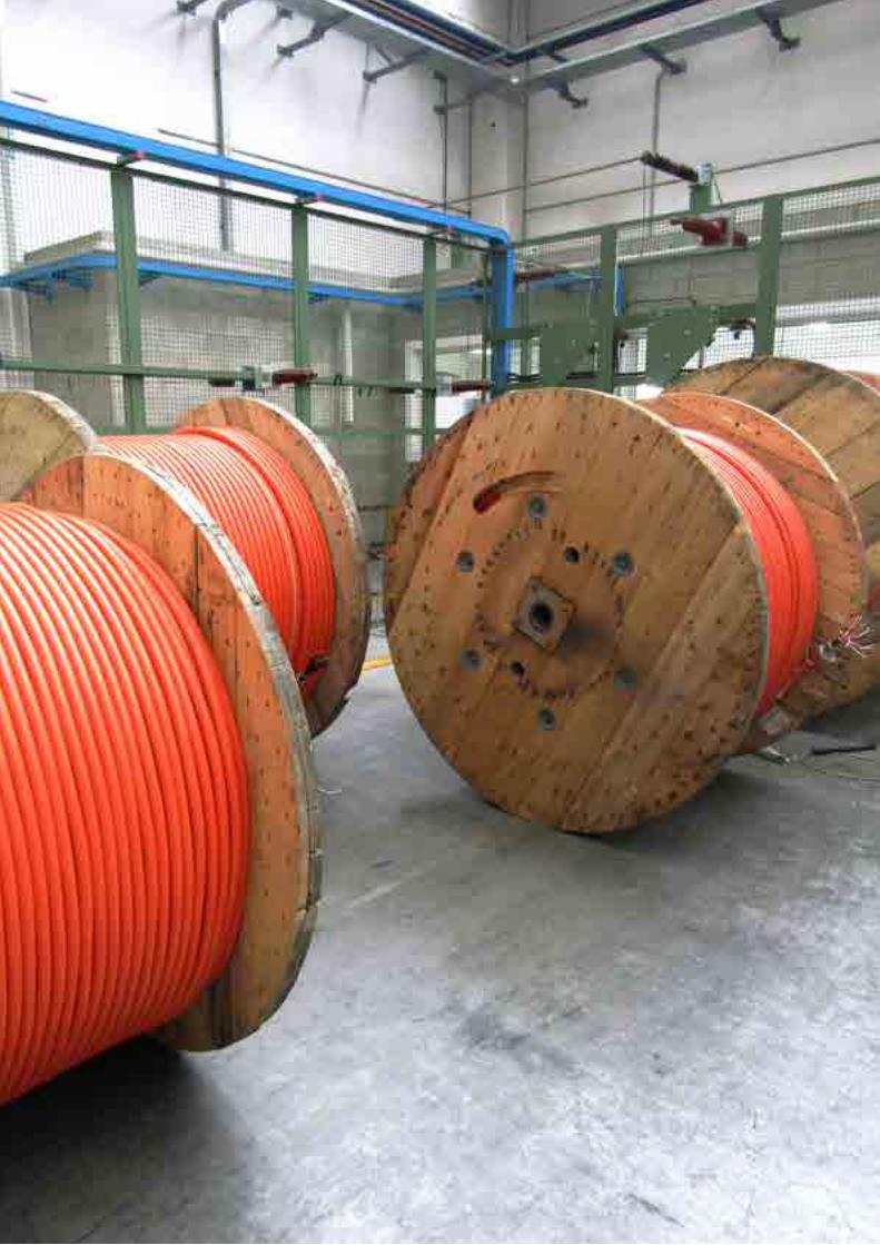

Conducting Value
CAVICEL SpA20096 Pioltello (Milano) - Italy
Via Caduti del Lavoro, 18/A
ph. +39 - 02 - 921.605.21fax +39 - 02 - 921.607.53
e-mail: [email protected]
MADE IN ITALY
Cavicel firmly believes in the importance of the quality of its products and it undertakes itself to produce them using clean technologies for the respect and the protection of the environment.
CORPORATE VIDEO
_All information contained in this brochure is believed to be accurate. Specifications can change at any time, according to technical developments and market changes.
All rights reserved. No part of this document may be reproduced in any form or by any means, without the prior written permission from Cavicel SpA.
Cavicel SpA (DMCC Branch)Fortune Executive TowerOffice 406 - Plot No. T1Jumeirah Lakes Towers
Dubai - UAE - PO Box 7042
ph. +971 4.4581199fax +971 4.4581144
e-mail: [email protected]
DUBAI BRANCH OFFICE


