INSTRUMENTATION FOR MEASURING LAKE AND RESERVOIR EVAPORATION BY THE ENERGY-BUDGET AND MASS-TRANSFER METHODS BY ALEX M. STURROCK, JR. U.S. GEOLOGICAL SURVEY Open-File Report 84-863 NSTL, MISSISSIPPI 1985
Transcript
INSTRUMENTATION FOR MEASURING LAKE
AND RESERVOIR EVAPORATION BY THE
ENERGY-BUDGET AND MASS-TRANSFER METHODS
BY ALEX M. STURROCK, JR.
U.S. GEOLOGICAL SURVEY
Open-File Report 84-863
NSTL, MISSISSIPPI 1985
UNITED STATES DEPARTMENT OF THE INTERIOR
WILLIAM P. CLARK, Secretary
GEOLOGICAL SURVEY
Dallas L. Peck, Director
For additional information write to: Copies of this reportcan be purchased from:
Chief, Hydrologic Instrumentation Facility Open-File Services Section U.S. Geological Survey, Bldg. 2101 Western Distribution Branch NSTL, MS 39529 Box 25425, Federal Center
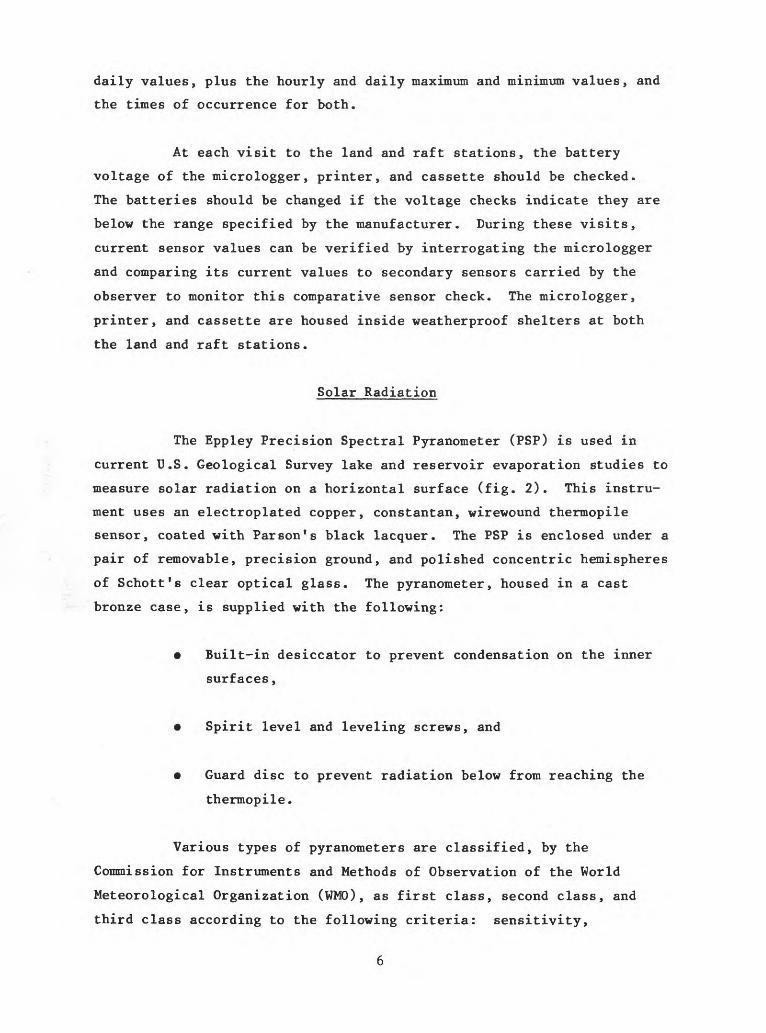
stability, temperature, selectivity, linearity, time constant, cosine
response, and azimuth response. The PSP has a WHO first-class
instrument rating.
When installing the pyranometer at the field site, the
instrument should be located:
So that it will be free of any obstructions above the
plane of the sensing element, and
So that a shadow will not be cast upon it at any time.
The pyranometer is oriented with the emerging leads located north of the
receiving surface (in the Northern Hemisphere), and is leveled with the
aid of the leveling screws and spirit level. A twin conductor (AWG no.
20) waterproofed cable is employed to connect the pyranometer to its
recorder.
Because radiation measurements must be made by a stable
horizontal pyranometer, radiometers should be installed on the
shorelines of lakes and reservoirs rather than on pitching rafts. A
flat roof provides the best location for mounting a pyranometer. If
such a site cannot be obtained, a rigid stand with a horizontal top
surface should be used.
Pyranometers should be inspected, ideally, once a day. If
this condition cannot be met, the less frequent inspection should
consist of wiping the outer hemisphere clean and dry with a soft,
lint-free cloth; checking the spirit level; and checking the condition
of the desiccator installed in the pyranometer case. If the silica gel
drying agent is pink or white in color, it should be replaced.
Reflected Solar Radiation
A part of the solar radiation, incident to the water surface,
is reflected back to the atmosphere. The ratio of the reflected solar
radiation to incoming solar radiation, the reflectivity, is independent
of both windspeed and turbidity and depends primarily upon sun altitude
and cloud cover. In present lake and reservoir evaporation studies,
reflected solar radiation is determined indirectly from measurements of
incoming solar radiation using relationships developed by Koberg (1964,
fig. 36). The approximate range in values of reflected solar radiation
is from 6 percent of the incoming solar radiation during the summer to
about 10 percent during the winter.
Long-Wave Radiation
The techniques for, and problems of, measuring long-wave (or
atmospheric) radiation are somewhat different from those measuring solar
radiation. The more complex atmospheric regime is largely a result of
the emission and absorption of long-wave radiation by real materials
solids, liquids, and gases that make up the physical system of interest.
Long-wave (infrared) radiation is measured by a variety of
instruments called radiometers. Two general types of radiometers are:
spectral radiometers (pyrgeometers) that measure the radiation intensity
at each wavelength, and nonspectral radiometers (pyrradiometers) that
measure the total radiation received from a broad wavelength band. The
radiometer currently used by the U.S. Geological Survey for lake and
reservoir evaporation studies is the Eppley Precision Infrared
Radiometer (PIR). The PIR is a spectral radiometer that measures only
the incoming long-wave component of radiation on a horizontal surface
(fig. 3). This pyrgeometer was developed from the Eppley Precision
Spectral Pyranometer. It uses the same type of wirewound, plated, non-
wavelength-selective, thermopile detector and cast bronze case, with a
built-in desiccator, as the PSP Model. A thermistor battery-resistance
circuit (in addition to that employed for temperature compensation of
radiometer response) is incorporated to precisely compensate for detec
tor temperature. To isolate the atmospheric long-wave radiation from
the solar short-wave radiation during the daytime, the glass hemisphere
of the PSP has been replaced with a silicone hemisphere with vacuum-
deposited interference filter on its inner surface. The composite trans
mission of this pyrgeometer window is approximately 4 to 50 micrometers.
The installation and maintenance procedures for the pyrgeo
meter follow the same instructions given for the pyranometer with the
exception that the pyrgeometer detector-temperature battery (1.35 volts)
should be changed at 6-month intervals.
Figure 3. Eppley FIR showing silicone hemisphere, guard disc, desiccator, spirit level, and leveling screws.
To maintain the highest measurement accuracy, both the
pyranometer and pyrgeometer should be returned to the factory once a
year to verify their calibration.
Reflected Long-Wave Radiation
The reflectivity coefficient of a water surface for incoming
long-wave radiation is approximately 3 percent as determined by the
measurements of P. J. Robinson and J. A. Davies (1972). The reflected
long-wave radiation is computed as the product of incoming long-wave
radiation and the reflectivity coefficient.
10
Long-Wave Radiation Emitted by a Body of Water
The long-wave radiation emitted by a body of water is depend
ent on the temperature and emissivity of the water at the surface, and
is computed using the Stefan-Boltzmann law for black-body radiation with
an emissivity of 0.97 (Robinson and Davies, 1972).
The temperature of the water surface is measured at the raft
station using an epoxy-coated thermistor placed just below the water
surface. It is important that the thermistor be set so that it is just
barely covered when the water surface is smooth, and it bobs in and out
of the water when the surface become choppy.
Because the water surface temperature is an important param
eter in the energy-budget and mass-transfer studies, an analog water
temperature recorder, made by Marshalltown Manufacturing Inc., is used
to obtain a backup record of the water surface temperature. This
battery-operated recorder is mounted in the raft station shelter and
uses a spring-wound chart drive that operates for a week without
attention. At weekly visits to the raft station to change the surface-
water-temperature analog chart, a temperature check should be made with
jK).l° C, calibrated, mercury-in-glass thermometer to determine the
accuracy of the analog water-temperature record.
Net Energy Advected to a Body of Water
The net energy advected to a body of water is determined from
the product of the temperature and the volume of water entering and
leaving that body. Values of advected energy from the unmeasured
tributary inflow resulting from storm runoff may be estimated from
change in the water body elevation and the wet-bulb temperature recorded
during the storm. Using the analog temperature recorder described in
the previous section, water temperature is measured continuously at or
near the gaging station located near the principal sources of inflow to,
and outflow from, the water body.
11
Heat Transfer Between the Water and the Bottom Sediments
The transfer of heat between bottom sediments and water is
considered negligible for lakes and reservoirs with depths greater than
100 feet. However, in shallow water bodies where mixing by wind or
thermal-induced currents can result in a range of temperature variations
at the bottom, temperature measurements of the bottom sediments should
be taken to determine their value. By comparing the temperature of the
bottom sediments and the water layer adjacent to the bottom, the direc
tion of heat flow between the sediments and water can be determined.
Change in Energy Content of a Body of Water
The change in energy content of a lake or reservoir is
determined from thermal surveys conducted at intervals of approximately
2 weeks. During each survey, the variation of water temperature is
measured from the surface to the bottom at each measuring site (the
number varies from 10 to 25 depending on reservoir area) at specified
depth intervals. The temperature measurements are obtained with a
portable, battery-powered, VJhitney model TC-5A, underwater thermometer
accurate to +0.1° C (fig. 4). This unit uses a fast response thermistor
to sense the water temperature changes in the water column. Temperatures
are read directly from the meter dial or can be recorded on a 0- to
1-milliamp recorder.
At the beginning and end of a thermal survey, the recorder
readings are verified against a 4^0.1° C, precision, mercury-in-glass
thermometer. To obtain the incremental values for energy content of the
reservoir, the energy in each specified depth interval is computed as
the product of the temperature and volume of that layer; then the
products are summed to give the total energy for the reservoir. At each
measuring site of the thermal survey, the temperature of the bottom
sediments is measured by allowing the underwater temperature probe to
momentarily rest on the bottom sediments.
12
Figure 4. Whitney underwater thermometer.
Vapor Pressure
A nonventilated thermistor psychrometer is used to determine
the values of wet- and dry-bulb temperatures, Tw and Ta. The psychrom
eter has a tetraskelion radiation shield and a large coolie hat
developed for a thermocouple psychrometer by F. R. Bellaire and L. J.
Anderson (1951). The tetraskelion shield shown in figure 5 is con
structed with an upper and lower section to accommodate both the dry-
bulb (upper) and wet-bulb (lower) temperature sensors. This design
prevents wet-bulb cooling from affecting the dry-bulb sensor, regardless
of wind direction.
13
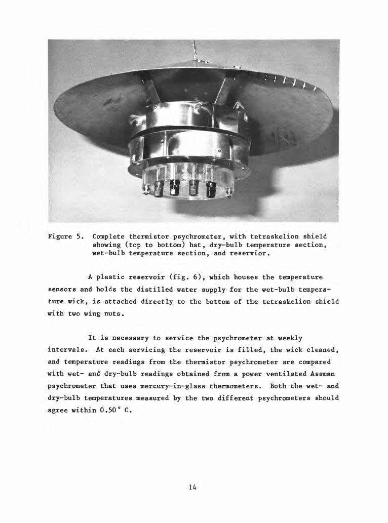
Figure 5. Complete thermistor psychrometer, with tetraskelion shield showing (top to bottom) hat, dry-bulb temperature section, wet-bulb temperature section, and reservior.
A plastic reservoir (fig. 6), which houses the temperature
sensors and holds the distilled water supply for the wet-bulb tempera
ture wick, is attached directly to the bottom of the tetraskelion shield
with two wing nuts.
It is necessary to service the psychrometer at weekly
intervals. At each servicing the reservoir is filled, the wick cleaned,
and temperature readings from the thermistor psychrometer are compared
with wet- and dry-bulb readings obtained from a power ventilated Assman
psychrometer that uses mercury-in-glass thermometers. Both the wet- and
dry-bulb temperatures measured by the two different psychrometers should
agree within 0.50° C.
14
Figure 6. Psychrometer unit showing (top to bottom) dry-bulb temperature sensor, wick covering wet-bulb temperature sensor, and reservoir.
For normal operation, the psychrometers at the land and raft
stations are mounted at 2-meter heights.
MASS-TRANSFER INSTRUMENTATION
Most equations for estimating evaporation by the mass-transfer
method take the following form:
^ = N u(e - e ) MT o a
(3)
where
N mass-transfer coefficient,
windspeed at some height above the water surface,
15
e = vapor pressure of saturated air at the temperature o
of the water surface,
e = vapor pressure of the air at some height above the a
water surface.
The units used in equation 3 have E expressed in inches per
day, u expressed in miles per hour, and e and e expressed inO 3.
millibars.
The mass-transfer method has the advantage of lower costs and
fewer instruments in relation to the energy-budget method, but this
advantage can be lost if the value of N is not known with reasonable
accuracy.
In current evaporation studies, instrumentation for both the
energy-budget and mass-transfer methods are run concurrently, and the N-
value is determined by establishing a linear relationship between the
energy-budget evaporation and the mass-transfer product, u(e - e ).
After the N-value has been established, the energy-budget
instruments are moved to another site and evaporation is determined
using the above equation.
The instruments used to determine the vapor pressure of
saturated air, the thermistor that measures water surface temperature,
the vapor pressure of the air, and the thermistorized wet- and dry-
psychrometer have been discussed in the energy-budget section of this
report. In place of the second thermistorized psychrometer used at the
land station for energy-budget studies, a hygrothermograph is installed
on or near the shore to serve as backup for the raft psychrometer used
for mass-transfer studies. The hygrothermograph utilized in these
studies, made by the Belfort Instrument Co., uses a liquid-filled
16
Bourdon tube and a human-hair element to sense air temperature and
relative humidity, respectively. The unit is powered by an 8-day,
spring-wound clock geared to the chart drive through an appropriate pair
of time-scale gears. A 7-day, 2-channel chart is used to record the ink
traces of the dual sensing elements for air temperature and relative
humidity. The hygrothermograph is housed in a medium-standard, cotton-
region-type shelter.
At weekly visits to the site, the readings from the hygrother
mograph are compared with readings from an Assman psychrometer to check
the accuracy of the record. If it is necessary to adjust the sensors in
the field, procedures described in the manufacturer's brochure should be
followed and the results noted on the chart. The hygrothermograph cali
bration should be checked once a year, in a constant humidity chamber,
by the manufacturer or at a qualified laboratory.
Windspeed
Currently, four cup-type anemometers are being used to deter
mine windspeed in lake and reservoir evaporation studies. The first is
a Gill 3-cup anemometer, made by R. M. Young Co., that utilizes * d.c.
tachometer generator whose analog output-voltage is directly propor
tional to windspeed. It can be connected to any of seven analog chan
nels on the micrologger. The second anemometer is also manufactured by
R. M. Young. This unit uses the same housing and 3-cup arrangement as
the generator type described above, but uses a photo-chopper transducer
circuit that provides a 4-volt, square-wave output whose frequency is
directly proportional to windspeed. This circuit requires a 5-volt,
d.c. input signal, thus a 12-volt battery with a power regulator is
supplied for its operation. This anemometer is used when all analog
channels are filled and additional windspeed data are needed at a raft
station. Leads from this anemometer must be connected to channel 8 of
the micrologger. Both the photo-chopper and generator type anemometers
operate through a windspeed range from 0 to 112 mi/h, respectively. The
third anemometer is a 3-cup unit, made by Met One, that uses a sealed,
magnetic reed switch to produce a series of contact closures at a rate
17
proportional to the windspeed. As with the photo-chopper above, this
anemometer can only be installed at channel 8 of the micrologger. It
does not require any external power supply, and has a 0- to 100-mi/h
range with a starting threshold value of 1.00 mi/h. The fourth unit is
a 3-cup, totalizing anemometer, manufactured by Belfort Instrument Co.,
that measures wind passage to the nearest tenth of a mile with a
5-digit, mechanical odometer directly coupled to the anemometer's gear
system. This anemometer serves as a backup instrument for the measure
ment of windspeed with a range of 0 to 100 mi/h and a starting threshold
of 2.0 mi/h. The odometer is read at each visit to the raft station,
and the difference between the readings is used to compute the average
windspeed during the period between readings.
Anemometers may be installed at 1-, 2-, 3-, and 4-meter levels
for profile windspeed measurements (fig. 7), depending on the number of
Figure 7. Raft station showing anemometers and thermistor psychrometers at multiple levels.
18
channels available from the micrologger. A mast, mounted at the
anchored end of the raft, supports the anemometers. Mounting the
anemometers at this position ensures that they will be on the upwind
side of the raft, and that no blockage will occur from the raft
instrument shelter. The windspeed at each level is recorded hourly on
the printer and the printout should be checked to ensure that the
highest-level anemometer shows the largest average value. If
malfunctions occur, the units are removed and replaced with spares kept
at the project office.
The anemometers are calibrated, at the beginning and end of
the open-water season for each study site, using a synchronous motor
calibration unit, or by direct measurement in a wind tunnel.
19
(p. 5U
REFERENCES
Andersen, E. R., 1954, Energy-budget studies, in water-loss
investigations Lake Hefner studies, Technical report: U.S.
Geological Survey Professional Paper 269, p. 71-119.
Bellaire, F. R., and Anderson, L. J., 1951, A thermocouple psychrometer
for field measurements: America Meteorological Society Bulletin
v. 32, no. 6, p. 217-220.
Koberg, G. E., 1964, Methods to compute long-wave radiation from the
atmosphere and reflected solar radiation from a water surface:
U.S. Geological Survey Professional Paper 272-F, 29 p.
Robinson, P. J., and Davies, J. A., 1972, Laboratory determinations of
water surface emissivity: Journal of Applied Meteorology, v. 11,